JP5486546B2 - Electronics - Google Patents
Electronics Download PDFInfo
- Publication number
- JP5486546B2 JP5486546B2 JP2011086200A JP2011086200A JP5486546B2 JP 5486546 B2 JP5486546 B2 JP 5486546B2 JP 2011086200 A JP2011086200 A JP 2011086200A JP 2011086200 A JP2011086200 A JP 2011086200A JP 5486546 B2 JP5486546 B2 JP 5486546B2
- Authority
- JP
- Japan
- Prior art keywords
- memory card
- substrate
- cover member
- side wall
- card holder
- Prior art date
- Legal status (The legal status is an assumption and is not a legal conclusion. Google has not performed a legal analysis and makes no representation as to the accuracy of the status listed.)
- Active
Links
- 239000000758 substrate Substances 0.000 claims description 67
- 238000004891 communication Methods 0.000 claims description 2
- 238000010586 diagram Methods 0.000 description 8
- 238000003780 insertion Methods 0.000 description 3
- 230000037431 insertion Effects 0.000 description 3
- 238000005192 partition Methods 0.000 description 2
- 230000004888 barrier function Effects 0.000 description 1
- 238000005452 bending Methods 0.000 description 1
- 238000001746 injection moulding Methods 0.000 description 1
- 239000002184 metal Substances 0.000 description 1
- 238000000034 method Methods 0.000 description 1
- 238000012986 modification Methods 0.000 description 1
- 230000004048 modification Effects 0.000 description 1
- 238000000465 moulding Methods 0.000 description 1
Images


Classifications
-
- Y—GENERAL TAGGING OF NEW TECHNOLOGICAL DEVELOPMENTS; GENERAL TAGGING OF CROSS-SECTIONAL TECHNOLOGIES SPANNING OVER SEVERAL SECTIONS OF THE IPC; TECHNICAL SUBJECTS COVERED BY FORMER USPC CROSS-REFERENCE ART COLLECTIONS [XRACs] AND DIGESTS
- Y02—TECHNOLOGIES OR APPLICATIONS FOR MITIGATION OR ADAPTATION AGAINST CLIMATE CHANGE
- Y02E—REDUCTION OF GREENHOUSE GAS [GHG] EMISSIONS, RELATED TO ENERGY GENERATION, TRANSMISSION OR DISTRIBUTION
- Y02E60/00—Enabling technologies; Technologies with a potential or indirect contribution to GHG emissions mitigation
- Y02E60/10—Energy storage using batteries
Description
本発明は、基板と、当該基板に実装されたメモリーカードコネクタと、当該基板に取り付けられて当該基板との間で当該メモリーカードコネクタを囲むメモリーカードホルダ用ハウジングと、を有する電子機器に関するものである。 The present invention relates to an electronic device having a substrate, a memory card connector mounted on the substrate, and a memory card holder housing attached to the substrate and surrounding the memory card connector. is there.
電子機器には、補助記憶装置としてメモリーカードを使用するために、メモリーカードが装着脱されるメモリーカードホルダユニットが組み込まれていることがある。メモリーカードホルダユニットは基板と当該基板に実装されたメモリーカードコネクタと当該基板に取り付けられて当該基板との間でメモリーカードコネクタを囲むメモリーカードホルダ用ハウジングとから構成され、当該メモリーカードコネクタにメモリーカードを接続することによって(メモリーカードホルダユニットにメモリーカードを装着(挿入)することによって)データをメモリーカードに記録し、或いはメモリーカードに記録された情報を読み込むことができる。 In order to use a memory card as an auxiliary storage device, an electronic device may incorporate a memory card holder unit into which the memory card is inserted or removed. The memory card holder unit includes a board, a memory card connector mounted on the board, and a memory card holder housing that is attached to the board and surrounds the memory card connector between the board and the memory card connector. By connecting the card (by inserting (inserting) the memory card into the memory card holder unit), data can be recorded on the memory card, or information recorded on the memory card can be read.
ところで、上述したように、メモリーカードコネクタは基板に実装されており、基板においては少なくともメモリーカードの大きさに相当するカード実装面積が必要となる。また、基板には、メモリーカードコネクタ以外に種々の部品が実装されており、薄型のメモリーカードコネクタに比べて厚い、例えば、LANコネクタ等が実装されている。これにより、メモリーカードコネクタの上部においてメモリーカード及びメモリーカードコネクタの占有面積とそれらよりも高さの高い他の部品とメモリーカードコネクタとの高さの差の積である余剰空間が存在していた。 By the way, as described above, the memory card connector is mounted on a substrate, and the substrate requires a card mounting area corresponding to at least the size of the memory card. In addition to the memory card connector, various components are mounted on the substrate, and a thicker, for example, LAN connector is mounted compared to the thin memory card connector. As a result, there is an excess space at the top of the memory card connector, which is the product of the height difference between the memory card and the area occupied by the memory card connector and the height of the other components higher than those and the memory card connector. .
特許文献1に開示されている電子機器は、電池収納室と記録媒体収納室とを近傍に配設して電池収納室の電池蓋を内蓋に、記録媒体収納室の記録媒体蓋を外蓋にした二重蓋構造とし、それぞれの蓋部材を閉状態とした際に内蓋と外蓋が当接して重ね合わせた状態となり蓋部材が必要とする占有面積を最小限にすることができることとしている。
In the electronic device disclosed in
特許文献1の技術では上述の通り蓋部材が必要とする占有面積を最小限にすることができるが、電子機器が有する記録媒体収納室と他の部品との高さの関係(高さの差)に基づいて電池収納室と記録媒体収納室とを形成するものではない。また、電池収納室と記録媒体収納室を囲うハウジングが一体成形されていないため、他(別機種)の電子機器に流用できず、機種毎に新たに設計し直さなければならないという問題があった。
In the technique of
本発明は、上述した問題点に鑑み、メモリーカードコネクタの上部に存在する余剰空間を有効利用しつつ、電子機器の薄型化を阻害しない汎用性の高いメモリーカードホルダ用ハウジングを備える電子機器を提供することを目的とする。 In view of the above-described problems, the present invention provides an electronic device provided with a highly versatile memory card holder housing that does not hinder the thinning of the electronic device while effectively using the excess space existing above the memory card connector. The purpose is to do.
上記目的を達成するために、本発明の電子機器は、基板と、前記基板との間にメモリーカードが着脱可能な隙間をあけて前記基板に実装されるメモリーカードコネクタと、前記基板に取り付けられることによって前記基板との間で前記メモリーカードコネクタを囲むメモリーカードホルダ用ハウジングと、を備える電子機器であって、前記メモリーカードホルダ用ハウジングは、天井壁と背面壁と両側面壁とを有して前面及び底面が開口したカバー部材と、前記カバー部材に連設部で連設され、当該連設部を二つ折りにして前記メモリーカードホルダ用ハウジングを前記基板に取り付けることで、前記基板と前記カバー部材とで囲まれる内部空間を前記基板に対して垂直方向に二分する連設板と、が一体に成形されてなり、前記メモリーカードコネクタは前記連設板により分けられた前記内部空間の下段空間に収納されていることことを特徴としている。 In order to achieve the above object, an electronic device of the present invention is attached to a substrate, a memory card connector mounted on the substrate with a detachable gap between the substrate and the memory card, and the substrate. A memory card holder housing surrounding the memory card connector with the substrate, the memory card holder housing having a ceiling wall, a back wall, and both side walls. A cover member having a front surface and a bottom surface opened, and a continuous portion connected to the cover member, and the memory card holder housing is attached to the substrate by folding the continuous portion in half. And a continuous plate that bisects the internal space surrounded by the members in a direction perpendicular to the substrate, and is formed integrally with the memory card. The connector is characterized in that it is housed in the lower space of the inner space which is divided by the communication up plate.
この構成によると、カバー部材と、基板とカバー部材とで囲まれる内部空間を二分する連設板とが連設部を介して一体に成形されているので、部品点数の削減を図ることができる。また、下段空間にメモリーカードコネクタが収納されることで、上段空間(メモリーカードコネクタの上部に存在する余剰空間)を有効利用できる。その際、上述したように、各収納部を囲うカバー部材を別々に形成する必要がない(各収納部を囲うカバー部材が一体に成形されている)ので、メモリーカードホルダ用ハウジングの高さ(厚さ)が高く(厚く)なるのを防ぐことができ、これにより、当該メモリーカードホルダ用ハウジングが組み込まれた電子機器の薄型化を阻害することがない。 According to this configuration, since the cover member and the continuous plate that bisects the internal space surrounded by the substrate and the cover member are integrally formed via the continuous portion, the number of parts can be reduced. . Further, by storing the memory card connector in the lower space, the upper space (the surplus space existing above the memory card connector) can be used effectively. At this time, as described above, there is no need to separately form a cover member that surrounds each storage portion (the cover member that surrounds each storage portion is integrally formed), so that the height of the memory card holder housing ( It is possible to prevent the (thickness) from becoming high (thick), and this does not hinder the thinning of the electronic device in which the memory card holder housing is incorporated.
また、上記構成の電子機器において、前記連設板により分けられた前記内部空間の上段空間にはバッテリが収納されていることが望ましい。 In the electronic device having the above-described configuration, it is preferable that a battery is accommodated in an upper space of the internal space divided by the continuous plate.
この構成によると、複数機種の電子機器で共用可能なバッテリを上段空間(メモリーカードコネクタの上部に存在する余剰空間)に収納(配置)することができるので、汎用性が向上する。 According to this configuration, since a battery that can be shared by a plurality of types of electronic devices can be stored (arranged) in the upper space (the surplus space existing above the memory card connector), versatility is improved.
また、上記構成の電子機器において、前記カバー部材の前面開口は前記連設板により前記上段空間の前面開口と前記下段空間の前面開口とに分割され、前記メモリーカードホルダ用ハウジングは当該上段空間の前面開口を覆う内蓋部と、前記内蓋部が閉状態で前記カバー部材の前面開口全体を覆う外蓋部とを有し、前記内蓋部は前記両側面壁の一方の前部に内蓋部用ヒンジを介して連設され、前記外蓋部は前記両側面壁の他方の前部に外蓋部用ヒンジを介して連設されていることが望ましい。 In the electronic device having the above-described configuration, the front opening of the cover member is divided into a front opening of the upper space and a front opening of the lower space by the connecting plate, and the memory card holder housing is formed in the upper space. An inner lid that covers the front opening; and an outer lid that covers the entire front opening of the cover member when the inner lid is in a closed state, and the inner lid is an inner lid at one front portion of the side walls. It is desirable that the outer lid portion is continuously provided via a hinge for part, and the outer lid portion is provided continuously to the other front portion of the side wall via the hinge for outer lid portion.
この構成によると、内蓋部用ヒンジと外蓋部用ヒンジが同一の側面壁に形成されていないので、外蓋部が開状態となるのに伴って内蓋部が開状態となるを防止することができる。すなわち、例えば、内蓋部用ヒンジ及び外蓋部用ヒンジが共に左側面壁の前部に形成されている場合において、閉状態である外蓋部を開状態にするために外蓋部に力を加えると、外蓋部用ヒンジに対して左方向の力が加えられる。これに伴って左側面壁が左方向に歪曲し、さらにこれに伴って、左側面壁に形成されている内蓋部用ヒンジが左方向に移動することにより閉状態である内蓋部が開状態となることが考えられる。そこで、このような場合に、内蓋部用ヒンジを右側面壁の前部に形成することにより、閉状態である内蓋部が開状態となるのを防ぐことができる。 According to this configuration, since the inner lid hinge and the outer lid hinge are not formed on the same side wall, the inner lid portion is prevented from being opened as the outer lid portion is opened. can do. That is, for example, when the inner lid hinge and the outer lid hinge are both formed at the front portion of the left side wall, a force is applied to the outer lid portion in order to open the outer lid portion in the closed state. When applied, a leftward force is applied to the outer lid hinge. Along with this, the left side wall is distorted in the left direction, and further, the inner lid hinge formed on the left side wall is moved in the left direction, so that the closed inner lid part is opened. It is possible to become. Therefore, in such a case, it is possible to prevent the closed inner cover from being opened by forming the inner cover hinge at the front of the right side wall.
また、上記構成の電子機器において、前記カバー部材の前記両側面壁の一方はその前部が側方に膨出されてポケット部が形成されることによって、前記バッテリが備える接続コードを前記上段空間から外に出して前記基板に実装されたバッテリコネクタに前記ポケット部内で接続することが望ましい。 Moreover, in the electronic device having the above-described configuration, one of the side wall surfaces of the cover member has a front portion bulged laterally to form a pocket portion, whereby a connection cord included in the battery is removed from the upper space. It is desirable to go out and connect to the battery connector mounted on the substrate within the pocket portion.
この構成によると、バッテリが備える接続コードを上段空間から外に出して基板に実装されたバッテリコネクタに接続することができる。また、ポケット部内で接続コードをバッテリコネクタに接続することができるので、バッテリの交換を容易に行うことができる。 According to this configuration, the connection cord included in the battery can be taken out of the upper space and connected to the battery connector mounted on the board. Further, since the connection cord can be connected to the battery connector in the pocket portion, the battery can be easily replaced.
本発明によれば、カバー部材と、基板とカバー部材とで囲まれる内部空間を二分する連設板とが連設部を介して一体に成形されているので、部品点数の削減を図ることができる。また、下段空間にメモリーカードコネクタが収納されることで、上段空間(メモリーカードコネクタの上部に存在する余剰空間)を有効利用できる。その際、上述したように、各収納部を囲うカバー部材を別々に形成する必要がない(各収納部を囲うカバー部材が一体に成形されている)ので、メモリーカードホルダ用ハウジングの高さ(厚さ)が高く(厚く)なるのを防ぐことができ、これにより、当該メモリーカードホルダ用ハウジングが組み込まれた電子機器の薄型化を阻害することがない。 According to the present invention, since the cover member and the continuous plate that bisects the internal space surrounded by the substrate and the cover member are integrally formed via the continuous portion, the number of parts can be reduced. it can. Further, by storing the memory card connector in the lower space, the upper space (the surplus space existing above the memory card connector) can be used effectively. At this time, as described above, there is no need to separately form a cover member that surrounds each storage portion (the cover member that surrounds each storage portion is integrally formed), so that the height of the memory card holder housing ( It is possible to prevent the (thickness) from becoming high (thick), and this does not hinder the thinning of the electronic device in which the memory card holder housing is incorporated.
以下に、本発明の本実施形態について、図面を参照して説明する。但し、以下に示す実施形態は、本発明の具体的思想を具体化するために本発明の電子機器の一例であるプログラマブル表示器を示すものであって、本発明をこのプログラマブル表示器に特定することを意味するものではなく、特許請求の範囲に含まれるその他の実施形態の電子機器にも等しく適応し得るものである。 Hereinafter, embodiments of the present invention will be described with reference to the drawings. However, the embodiment described below shows a programmable display which is an example of the electronic apparatus of the present invention in order to embody the specific idea of the present invention, and the present invention is specified to this programmable display. This does not mean that the present invention is equally applicable to electronic devices of other embodiments included in the scope of claims.
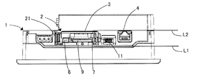
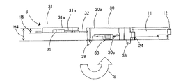
図1及び図2は、それぞれ本発明のプログラマブル表示器の外観を示す背面模式図及び底面模式図である。プログラマブル表示器1は、基板5(基板5はプログラマブル表示器1の内部に備えられ外部から視認することはできないが、図2の直線L1が基板5の位置に相当する)と、基板5の実装面に実装されたメモリーカードコネクタ7と(以下の説明において、「基板5に実装される」は「基板5の実装面に実装される」ことを意味し、「基板5に取り付けられる」は「基板5の実装面に取り付けられる」ことを意味するものとする。)、基板5に取り付けられることによって基板5との間でメモリーカードコネクタ7を囲むメモリーカードホルダ用ハウジング3とを有している。なお、以下の説明において、基板5とメモリーカードコネクタ7とメモリーカードホルダ用ハウジング3とからなる構成をメモリーカードホルダユニット2という。
1 and 2 are a schematic back view and a schematic bottom view showing the appearance of the programmable display device of the present invention, respectively. The
また、以下の説明において、「上下」は、基板5に対して垂直方向であって、メモリーカードコネクタ7が実装される基板5の実装面側が「上」、基板5の裏面側が「下」であることとする。また、「前後」は、メモリーカードコネクタ7が基板5に実装された状態において、メモリーカード9が挿入される挿入方向手前側が「前」、挿入方向奥側が「後」であることとする。また、「左右」は、基板5の実装面側を上としたときに基板5に取り付けられたメモリーカード用ハウジング3の前面開口に正対する観察者の左手側が「左」、右手側が「右」であることとする。
In the following description, “upper and lower” is a direction perpendicular to the
基板5は、プログラマブル表示器1に内蔵されている。基板5には、メモリーカードコネクタ7以外に、例えば、図1及び図2に示すLANコネクタ4や図2に示すバッテリコネクタ6等のコネクタ類やコンデンサ等が実装されている。
The
メモリーカードコネクタ7は基板5との間にメモリーカード9が着脱可能な隙間をあけて基板5に実装されている。そして、当該隙間にメモリーカード9を挿入することによってメモリーカード9内に情報を書き込み、或いはメモリーカード9内に記憶された情報を読み出すことができる。メモリーカード9としては、例えば、SIMカード(登録商標)、SDカード(登録商標)、スマートメディア(登録商標)、メモリースティックDuoカード(登録商標)等を挙げることができる。
The memory card connector 7 is mounted on the
メモリーカードホルダ用ハウジング3は、底面(下面)及び前面(正面)が開口して形成されており、当該底面開口が基板5に取り付けられることによって基板5との間でメモリーカードコネクタ7を囲む。メモリーカードホルダ用ハウジング3は、後述するように基板5とメモリーカードホルダ用ハウジング3(メモリーカードホルダ用ハウジング3が有するカバー部材30)とで囲まれる内部空間を基板5に対して垂直方向に二分する板部材(図4に示す連設板31)を有する。メモリーカードコネクタ7は二分された内部空間の下段に収納され(以下、「二分された内部空間の下段」を「下段空間」という。)、二分された内部空間の上段にはバッテリ(電池)8が収納される(以下、「二分された内部空間の上段」を「上段空間」という。)。
The memory
なお、以上及び以下において、メモリーカード用ハウジング3の前面開口は、カバー部材30の前面開口と同一部分を指し示し、メモリーカード用ハウジング3の底面開口は、カバー部材30の底面開口と同一部分を指し示すものとする。
In the above and below, the front opening of the
メモリーカード用ハウジング3の前面開口は、メモリーカード用ハウジング3が基板5に取り付けられている状態において、メモリーカード9の着脱及びバッテリ8の出し入れを可能にする開口である。
The front opening of the
また、メモリーカードホルダ用ハウジング3は、二つの蓋部材(内蓋部11と外蓋部21)を有する。内蓋部11はメモリーカード用ハウジング3の前面開口の一部(上段空間の前面開口(後述する開口部42a及び44a))を覆う蓋部であり、外蓋部21はメモリーカード用ハウジング3の前面開口全体を覆う蓋部である。なお、図1及び図2は、内蓋部11と外蓋部21が共に開状態であるときのプログラマブル表示器1の外観を示す図であるが、内蓋部11と外蓋部21が共に閉状態であるときには、外蓋部21のみが露出した(外部から視認可能な)状態になる(詳細は後述)。
The memory
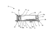
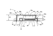
図3は、本発明のプログラマブル表示器1が備えるメモリーカードホルダユニット2を示す正面模式図である。また、図4は、本発明のプログラマブル表示器1が備えるメモリーカードホルダユニット2を示す正面模式図の断面図である。
FIG. 3 is a schematic front view showing the memory
上述したように、メモリーカードホルダユニット2は、基板5とメモリーカードコネクタ7とメモリーカードホルダ用ハウジング3とからなる。
As described above, the memory
メモリーカードホルダ用ハウジング3は、カバー部材30を有し、当該カバー部材30は、天井壁30aと両側面壁(左側面壁30b及び右側面壁30c)と背面壁30dとを有して底面及び前面が開口している。両側面壁と背面壁30dの底部には、カバー部材30を基板5に固定するための係合フック38が合計三つ形成されており、当該係合フック38がこれらに対応するように基板5に設けられた孔部39に挿入されることによって、メモリーカードホルダ用ハウジング3が基板5に固定される。
The memory
また、メモリーカードホルダ用ハウジング3は、メモリーカードホルダ用ハウジング3が基板5に固定された状態において(メモリーカードホルダ用ハウジング3を基板5に取り付けることで)、基板5とメモリーカードホルダ用ハウジング3(メモリーカードホルダ用ハウジング3が有するカバー部材30)とで囲まれる内部空間を、基板5に対して垂直方向に二分する連設板31を有している。そして、カバー部材30の天井壁30aと連設板31との間に形成される空間はバッテリ収納部42を構成し、連設板31と基板5との間に形成される空間はメモリーカード収納部41を構成する。
In addition, the memory
カバー部材30の左側面壁30bは、その前部が側方(メモリーカード9の挿入方向に直角な方向且つ基板5の実装面に略平行方向)に膨出して形成されていることにより、基板5とメモリーカードホルダ用ハウジング3(メモリーカードホルダ用ハウジング3が有するカバー部材30)とで囲まれる内部空間において、メモリーカード収納部41及びバッテリ収納部42の左側に、左側面壁30bの前部(左側面壁30bにおいて膨出して形成されている部分)と基板5とカバー部材30の天井壁30aに囲まれるようにして形成されるポケット部から構成される接続コード収納部44が形成される。つまり、本実施形態において、基板5とメモリーカードホルダ用ハウジング3(メモリーカードホルダ用ハウジング3が有するカバー部材30)とで囲まれる内部空間は、メモリーカード収納部41とバッテリ収納部42と接続コード収納部44とに分けられている。
The front side of the
なお、バッテリ収納部42と接続コード収納部44との間は、連設板31によって仕切られておらず、バッテリ収納部42に収納されたバッテリ8が備える接続コードと基板5に実装されたバッテリコネクタ6とをポケット部(接続コード収納部44)内で接続することができる。これにより、内蓋部11がバッテリ収納部42の開口部42aを閉鎖している状態であっても、バッテリ8と基板5に実装されたバッテリコネクタ6を接続することができる。このように、バッテリ収納部42と接続コード収納部44とは、連設板31によって仕切られていないので、本実施形態における上部空間は、バッテリ収納部42と接続コード収納部44とから構成されているということができる。
The
一方、メモリーカード収納部41と接続コード収納部44との間は、連設板31が有する左側面壁31bによって仕切られている。これにより、バッテリ8が備える接続コードが接続コード収納部44からメモリーカード収納部41に入ってくるのを防ぐことができる。
On the other hand, the memory
メモリーカード収納部41とバッテリ収納部42と接続コード収納部44とは、それぞれ開口部41a、42a、44aが形成されており、これら開口部41a、42a、44aがカバー部材30の前面開口を構成している。言い換えると、連設板31はカバー部材30の前面開口を、上段空間の前面開口と下段空間の前面開口とに分割する。開口部42aと開口部44aとの間は、連設板31により仕切られていないため、上段空間の前面開口は、開口部42aと開口部44aとから構成され、下段空間の前面開口は開口部41aから構成される。なお、開口部41a、42aはそれぞれメモリーカード9、バッテリ8の出し入れを行うために形成されている。また、開口部44aはバッテリが備える接続コードを基板に実装されたバッテリコネクタ6に接続するために形成されている。
The memory
そして、メモリーカードホルダ用ハウジング3は、開口部42aと44aと(上段空間の前面開口)を覆う内蓋部11と、開口部41a、42a、44a(カバー部材30の前面開口全体)を覆う外蓋部21を有する。以下、内蓋部11及び外蓋部21について説明する。
The memory
カバー部材30の右側面壁30cの前部には、内蓋部11の付け根部分として内蓋部用ヒンジ14が形成されている。内蓋部11の先端部には、内蓋部11が閉状態であるときに左側面壁30bに向く面に係止溝13を有するU字状のフック部12が形成されており、当該フック部12の係止溝13が、カバー部材30の左側面壁30bの前部に右側面壁30cに向かって突出形成されている係止受52に係止されることによって内蓋部11はバッテリ収納部42の開口部42aを閉鎖する位置に維持される。
An
なお、本実施形態では内蓋部11が凹形状の係止溝13を有し、左側面壁30bが凸形状の係止受52を有することとしているが、内蓋部11が凸形状の係止受を有し、左側面壁30bが凸形状の係止溝を有することとしてもよい。以下の外蓋部21においても同様である。
In this embodiment, the
カバー部材30の左側面壁30bの前部には、外蓋部21が取り外し可能に取り付けられる(連設される)外蓋部用ヒンジ24(図5及び図6参照)が形成されている。外蓋部21はそれを閉状態にしたときに、先に閉状態にされている内蓋部11の外面に当接する。つまり、外蓋部21は内蓋部11が閉状態で(内蓋部11が上段空間の前面開口(開口部42a及び開口部44a)を閉鎖している状態で)カバー部材30の前面開口全体を覆う蓋部である。従って内蓋部11が開状態(内蓋部11が上段空間の前面開口(開口部42a及び開口部44a)を開放している状態)であるときには、内蓋部11が邪魔をして外蓋部21を閉状態にすることができない。
An outer lid hinge 24 (see FIGS. 5 and 6) to which the
なお、外蓋部21の先端部には、外蓋部21が閉状態であるときに右側面壁30cに向く面に係止溝23を有するU字状のフック部22が形成されており、当該フック部22の係止溝23がカバー部材30の右側面壁30cの前部に左側面壁30bに向かって突出形成されている係止受51に係止されることによって外蓋部21が、カバー部材30の前面開口全体(開口部41a、42a、44a)を閉鎖する位置に維持される(図5及び図6を参照、詳細は後述)。
A
つまり、内蓋部11はカバー部材30の右側面壁30cの前部に形成された内蓋部用ヒンジ14を支点とする右開きとなり、一方外蓋部21はカバー部材30の左側面壁30bの前部に形成された外蓋部用ヒンジ24を支点とする左開きとなる。
That is, the
なお、本実施形態においては内蓋部用ヒンジ14をカバー部材30の右側面壁30cの前部に形成し、外蓋部用ヒンジ24をカバー部材30の左側面壁30bの前部に形成しているが、これには限られず内蓋部用ヒンジ14をカバー部材30の左側面壁30bの前部に形成し、外蓋部用ヒンジ24をカバー部材30の右側面壁30cの前部に形成することとしてもよい。但し、内蓋部用ヒンジ14と外蓋部用ヒンジ24を同一側面壁の前部(例えば、共にカバー部材30の左側面壁30bの前部)に形成すると、閉状態である外蓋部21を開状態にするために外蓋部21に力を加えたときに、外蓋部用ヒンジ24にかかる力が左側面壁30bを左方向に歪曲し、これに伴って左側面壁30bの前部に形成されている内蓋部用ヒンジ14も左方向に移動することによって、フック部12の係止溝13と係止受52の係止が外れて閉状態である内蓋部11が開状態となる可能性がある。従って、内蓋部用ヒンジ14と外蓋部用ヒンジ24とは、一方をカバー部材30の右側面壁30bの前部に形成し、他方をカバー部材30の左側面壁30cの前部に形成することが望ましい。
In this embodiment, the
また、本実施形態において、カバー部材30と内蓋部11が内蓋部用ヒンジ14を介して一体に成形されているのに対し、外蓋部21はカバー部材30と一体に成形されていない(外蓋部用ヒンジ24に取り外し可能に取り付けられている)が、用途に応じて内蓋部11を内蓋部用ヒンジ14に取り外し可能に取り付けることとしてもよいし、カバー部材30と外蓋部21とが外蓋部用ヒンジ24を介して一体に成形されることとしてもよい。すなわち、メモリーカード9を出し入れするときなど頻繁に開閉される蓋部をカバー部材30と一体に成形すると、ヒンジが破損しやすくなるため蓋部をカバー部材30と別部品とすることが望ましい。一方、バッテリの落下を防止するために必要であるが、通常であれば何年間も交換する必要がなく、頻繁に開閉されることが想定されない蓋部であれば、カバー部材30と一体に成形することによってメモリーカードホルダ用ハウジング3の部品点数の削減を図ることができる。
Further, in the present embodiment, the
カバー部材30の内部における連設板31の位置について詳説すると、カバー部材30の右側面壁30cには段部30eが形成されており、連設板31はカバー部材30の内部において、段部30eに当たる(接触する)ことにより、カバー部材30の内部における位置が決定される。そして、後述するカバー部材30に形成されているハウジング側係合部33、34と連設板31に形成されている連設板側係合部35、36が係合することによって、カバー部材30の段部30eによって決定された位置で連設板31を保持する。
The position of the connecting
メモリーカード収納部41の高さH1とバッテリ収納部42の高さH2は、その内部に収納されるメモリーカードコネクタ7やバッテリ8の高さによって定まり、メモリーカードホルダ用ハウジング3の高さH3は、メモリーカード収納部41の高さH1とバッテリ収納部42の高さH2とカバー部材30の天井壁30a及び連設板31の厚みとによって定まるものである。従って、基板5に実装される他の部品(例えばLANコネクタ4)の高さがメモリーカードホルダ用ハウジング3の高さH3より低い場合には、メモリーカード収納部41及びバッテリ収納部42に収納されるメモリーカードコネクタ7やバッテリ8を変更することによってメモリーカードホルダ用ハウジング3の高さH3を調整することができる。
The height H1 of the memory
例えば、図2に示すようにメモリーカードホルダ用ハウジング3が組み込まれるプログラマブル表示器1にはLANケーブルが挿入可能なLANコネクタ4が備えられており、当該LANコネクタ4はメモリーカードホルダ用ハウジング3と同様に基板5に実装されている。そして、図2の直線L1と直線L2が示すようにメモリーカードホルダ用ハウジング3の高さをLANコネクタ4の高さよりもやや低く形成することによって、メモリーカード収納部41の上段空間を有効活用でき、プログラマブル表示器1の薄型化を阻害することがない(メモリーカードホルダ用ハウジング3の高さがLANコネクタ4の高さよりも高くなると、メモリーカード収納部41の上段空間は有効活用できるが、プログラマブル表示器1の薄型化に反することとなる)。
For example, as shown in FIG. 2, the
図5は、本発明の電子機器が備えるメモリーカードホルダ用ハウジング3の構造を示す第1の上面模式図である。また、図6は、本発明の電子機器が備えるメモリーカードホルダ用ハウジング3の構造を示す第2の上面模式図である。
FIG. 5 is a first schematic top view showing the structure of the memory
なお、図5において、メモリーカードホルダ用ハウジング3が備える外蓋部21は開状態であり、内蓋部11は閉状態である。一方、図6において、メモリーカードホルダ用ハウジング3が備える外蓋部21及び内蓋部11は共に閉状態である。
In FIG. 5, the
上述したように、外蓋部21は外蓋部用ヒンジ24に取り外し可能に取り付けられ、当該外蓋部用ヒンジ24を支点として閉状態となり、或いは開状態となる。外蓋部21が閉状態になるときについて詳説すると、外蓋部21の先端部には、外蓋部21が閉状態であるときに右側面壁30cに向く面に係止溝23を有するU字状のフック部22が形成されており、当該フック部22の係止溝23がカバー部材30の右側面壁30cの前部に右側面壁30bに向かって突出形成されている係止受51に係止されることによって外蓋部21が、内蓋部11によって閉鎖されたバッテリ収納部42の開口部42aとメモリーカード収納部41の開口部41aを共に覆う。
As described above, the
また、図6に示すように、外蓋部21は閉状態において内蓋部11の外面に当接して内蓋部11が開状態となることを阻止している。
In addition, as shown in FIG. 6, the
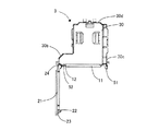
次に、上述したような本発明のメモリーカードホルダ用ハウジング3の構造について説明する。図7は、本発明のメモリーカードホルダ用ハウジング3の展開構造を示す上面模式図であり、図8は、本発明のメモリーカードホルダ用ハウジング3の展開構造を示す左側面模式図である。図7及び図8において、メモリーカードホルダ用ハウジング3はプラスチックで形成されており、組み立てることによって上述したようなメモリーカードホルダ用ハウジング3を形成することができる。なお、本実施形態及び以下の実施形態において、メモリーカードホルダ用ハウジング3は、プラスチックの射出成形で形成されていることとしているが、板金のプレス成形で形成されるものであってもよい。
Next, the structure of the memory
メモリーカードホルダ用ハウジング3は、本体を形成するカバー部材30と、カバー部材30を仕切る連設板31と、カバー部材30と連設板31を連設する薄肉ヒンジ部により構成された連設部32と、内蓋部11と、カバー部材30と内蓋部11を連設する内蓋部用ヒンジ14との一体成形体と、上述した外蓋部21を含む。なお、外蓋部21は図7及び図8において、説明の簡略化のため図示していないが、上述したように外蓋部用ヒンジ24に取り外し可能に取り付けられている。
The memory
カバー部材30は、両側面壁(左側面壁30b及び右側面壁30c)と背面壁30dとを有する。左側面壁30bの前部は、側方に膨出した形状に形成されており、併せてカバー部材30の天井壁30aが上面視で略L字形状となるように形成されている。左側面壁30bにはハウジング側第1係合部33が形成され、右側面壁30cにはハウジング側第2係合部34が形成されている。また、左側面壁30b及び右側面壁30cは後述する連設板31の左側面壁31b及び右側面壁31cを嵌合させるために一部切り欠いた形状に形成されている。
The
連設板31は、ベース壁31aと両側面壁(左側面壁31b及び右側面壁31c)とを含む。左側面壁31bと右側面壁31cとはベース壁31aの両端部を略直角方向に折り曲げること(立ち上げること)によって形成される。左側面壁31bには、ハウジング側第1係合部33に係合する連設板側第1係合部35が形成されており、右側面壁31cにハウジング側第2係合部34に係合する連設板側第2係合部36が形成されている。連設板31はカバー部材30の底面開口に連設された連設部32を介してカバー部材30と連設しており、連設部32は連設板31をカバー部材30の底面側に折り曲げ可能に形成されている。
The connecting
左側面壁31bの長さは、メモリーカードホルダ用ハウジング3を基板5に取り付けたときに、メモリーカード収納部41と接続コード収納部44との間に突き出す長さに形成されている。従って、メモリーカード収納部41と接続コード収納部44との間を、連設板31の左側面壁31bが塞ぐ(連設板31の左側面壁31bがメモリーカード収納部41と接続コード収納部44の境界を構成する障壁(仕切り)となる)ので、上述したように、接続コードが接続コード収納部44からメモリーカード収納部41に入ることを防ぐことができる。
The
図8に示すように、カバー部材30の高さH4は、カバー部材30の天井壁30aと連設板31との高さの差H5よりも高くなるように形成されている。これによって、連設部32を二つ折りにして連設板31を矢印Sが示すように、カバー部材30の底面側からカバー部材30の内部に入り込ませることでハウジング側係合部33、34と連設板側係合部35、36とをそれぞれ係合させた際に、連設板31が基板5とカバー部材30とで囲まれる内部空間を連設板31とカバー部材30の天井壁30aとの間に形成される空間(図3及び図4に示すバッテリ収納部42)と、連設板31と基板5との間に形成される空間(図3及び図4に示すメモリーカード収納部41)とに分ける。
As shown in FIG. 8, the height H <b> 4 of the
カバー部材30の天井壁30aには三方が天井壁30aから切り離されたバネ片37がカバー部材30の内部に向かって沈み込むように形成されている。また、バネ片37はカバー部材30の天井壁30aに向かい合わせに一対に形成されておりバッテリ収納部に収納される部品を天井壁30aから連設板31に向かって押さえつけることにより、部品を連設板31に固定する。
On the
<変形例>
上記実施形態においては、カバー部材30の左側面壁30bの前部が側方に膨出して形成されていることとしているが、カバー部材30の右側面壁30cの前部が側方に膨出して形成されていることとしてもよい。その場合には、連設板31の右側面壁31cの長さをメモリーカード収納部41と接続コード収納部44との間に突き出す長さに形成する(連設板31の右側面壁31cがメモリーカード収納部41と接続コード収納部44の境界を構成する障壁(仕切り)となる)。また、バッテリ収納部42に収納されるバッテリ8が、基板5との接続を必要としない部品である場合には、カバー部材30の左側面壁30bの前部を側方に膨出しないこととしてもよい。
<Modification>
In the above embodiment, the front part of the
本発明は、基板と、当該基板に実装されたメモリーカードコネクタと、当該基板に取り付けられて当該基板との間で当該メモリーカードコネクタを囲むメモリーカードホルダ用ハウジングと、を有する電子機器に利用できる。 The present invention can be used for an electronic device having a substrate, a memory card connector mounted on the substrate, and a memory card holder housing attached to the substrate and surrounding the memory card connector. .
1 プログラマブル表示器
2 メモリーカードホルダユニット
3 メモリーカードホルダ用ハウジング
7 メモリーカードコネクタ
9 メモリーカード
11 内蓋部
21 外蓋部
30 カバー部材
31 連設板
32 連設部
41 メモリーカード収納部
42 バッテリ収納部
44 接続コード収納部
DESCRIPTION OF
Claims (2)
前記基板との間にメモリーカードが着脱可能な隙間をあけて前記基板に実装されるメモリーカードコネクタと、
前記基板に取り付けられることによって前記基板との間で前記メモリーカードコネクタを囲むメモリーカードホルダ用ハウジングと、
を備える電子機器であって、
前記メモリーカードホルダ用ハウジングは、
天井壁と背面壁と両側面壁とを有して前面及び底面が開口したカバー部材と、
前記カバー部材に連設部で連設され、当該連設部を二つ折りにして前記メモリーカードホルダ用ハウジングを前記基板に取り付けることで、前記基板と前記カバー部材とで囲まれる内部空間を前記基板に対して垂直方向に二分する連設板と、
が一体に成形されてなり、前記メモリーカードコネクタは前記連設板により分けられた前記内部空間の下段空間に収納され、前記内部空間の上段空間にはバッテリが収納されることを特徴とする電子機器。 A substrate,
A memory card connector mounted on the substrate with a detachable gap between the memory card and the substrate;
A memory card holder housing that surrounds the memory card connector with the substrate by being attached to the substrate;
An electronic device comprising:
The memory card holder housing is
A cover member having a ceiling wall, a back wall, and both side walls and having front and bottom surfaces opened;
An internal space surrounded by the substrate and the cover member is formed by connecting the cover member to the substrate by connecting the memory card holder housing to the substrate. A continuous plate that bisects in the vertical direction
Electronic There will be molded integrally, the memory card connector is housed in the lower space of the inner space which is divided by the communication up plate, the battery in the upper space of the inner space, characterized in Rukoto housed machine.
前記内蓋部は前記両側面壁の一方の前部に内蓋部用ヒンジを介して連設され、前記外蓋部は前記両側面壁の他方の前部に外蓋部用ヒンジを介して連設されていることを特徴とする請求項1に記載の電子機器。 The front opening of the cover member is divided into a front opening of the upper space and a front opening of the lower space by the connecting plate, and the housing for the memory card holder covers an inner lid portion covering the front opening of the upper space, An outer lid covering the entire front opening of the cover member in a closed state of the inner lid,
The inner lid portion is connected to one front portion of the both side wall via an inner lid hinge, and the outer lid portion is connected to the other front portion of the both side wall via an outer lid hinge. The electronic device according to claim 1, wherein the electronic device is provided.
Priority Applications (1)
| Application Number | Priority Date | Filing Date | Title |
|---|---|---|---|
| JP2011086200A JP5486546B2 (en) | 2011-04-08 | 2011-04-08 | Electronics |
Applications Claiming Priority (1)
| Application Number | Priority Date | Filing Date | Title |
|---|---|---|---|
| JP2011086200A JP5486546B2 (en) | 2011-04-08 | 2011-04-08 | Electronics |
Publications (3)
| Publication Number | Publication Date |
|---|---|
| JP2012221734A JP2012221734A (en) | 2012-11-12 |
| JP2012221734A5 JP2012221734A5 (en) | 2013-09-26 |
| JP5486546B2 true JP5486546B2 (en) | 2014-05-07 |
Family
ID=47273024
Family Applications (1)
| Application Number | Title | Priority Date | Filing Date |
|---|---|---|---|
| JP2011086200A Active JP5486546B2 (en) | 2011-04-08 | 2011-04-08 | Electronics |
Country Status (1)
| Country | Link |
|---|---|
| JP (1) | JP5486546B2 (en) |
Families Citing this family (2)
| Publication number | Priority date | Publication date | Assignee | Title |
|---|---|---|---|---|
| KR101684358B1 (en) | 2013-09-30 | 2016-12-20 | 주식회사 엘지화학 | Battery Pack Having Electric Insulating Pack Case |
| DE102016224442A1 (en) * | 2016-12-08 | 2018-06-14 | Robert Bosch Gmbh | Battery and method of manufacturing a battery |
Family Cites Families (7)
| Publication number | Priority date | Publication date | Assignee | Title |
|---|---|---|---|---|
| JPH1092167A (en) * | 1996-07-23 | 1998-04-10 | Konica Corp | Memory card attachment device |
| JP2001298646A (en) * | 2000-04-17 | 2001-10-26 | Olympus Optical Co Ltd | Electronic camera device |
| JP4472913B2 (en) * | 2001-08-10 | 2010-06-02 | 株式会社ニコン | Electronic still camera |
| JP3535860B2 (en) * | 2002-02-14 | 2004-06-07 | キヤノン株式会社 | Electronics |
| JP4098302B2 (en) * | 2004-12-13 | 2008-06-11 | 山一電機株式会社 | Card connector |
| JP2007165147A (en) * | 2005-12-14 | 2007-06-28 | Canon Inc | Electronic apparatus |
| JP5404085B2 (en) * | 2009-02-12 | 2014-01-29 | キヤノン株式会社 | Electronics |
-
2011
- 2011-04-08 JP JP2011086200A patent/JP5486546B2/en active Active
Also Published As
| Publication number | Publication date |
|---|---|
| JP2012221734A (en) | 2012-11-12 |
Similar Documents
| Publication | Publication Date | Title |
|---|---|---|
| JP5162015B1 (en) | Memory card storage case | |
| JP6498409B2 (en) | Connector assembly | |
| JP5486546B2 (en) | Electronics | |
| JP2017142350A (en) | Display device and extension board receptor | |
| US20120014055A1 (en) | Computer case with guiding plates for drives | |
| JP5294429B2 (en) | Electronics | |
| JP6865113B2 (en) | Storage device | |
| JP2015233087A (en) | Housing | |
| JP2008263433A (en) | Electronic device | |
| JP5971696B2 (en) | Electronic device casing and electronic device decorative panel | |
| US9507377B2 (en) | Electronic device | |
| JP2006019574A (en) | Cabinet structure for electronic apparatus | |
| TW201635280A (en) | Recording medium device housing case, recording medium unit, and electronic apparatus | |
| JP2007241416A (en) | Storage device and electronic equipment | |
| JP6085650B2 (en) | Housing for computer system, computer system and assembly method | |
| JP6582715B2 (en) | Information processing device | |
| JP4951628B2 (en) | Storage case lock structure | |
| JP5301138B2 (en) | Mobile terminal device | |
| JP5301139B2 (en) | Mobile terminal device | |
| CN218163210U (en) | Waterproof type circuit board protection box | |
| JP6822077B2 (en) | Case | |
| JP5434645B2 (en) | USB device, USB device connection structure, and electronic device system | |
| JP2012139462A (en) | Panel structure of electronic apparatus | |
| JP4347317B2 (en) | Equipment storage box | |
| JP5301137B2 (en) | Mobile terminal device |
Legal Events
| Date | Code | Title | Description |
|---|---|---|---|
| A521 | Request for written amendment filed |
Free format text: JAPANESE INTERMEDIATE CODE: A523 Effective date: 20130731 |
|
| A621 | Written request for application examination |
Free format text: JAPANESE INTERMEDIATE CODE: A621 Effective date: 20130731 |
|
| A131 | Notification of reasons for refusal |
Free format text: JAPANESE INTERMEDIATE CODE: A131 Effective date: 20131224 |
|
| A977 | Report on retrieval |
Free format text: JAPANESE INTERMEDIATE CODE: A971007 Effective date: 20131225 |
|
| A521 | Request for written amendment filed |
Free format text: JAPANESE INTERMEDIATE CODE: A523 Effective date: 20140128 |
|
| TRDD | Decision of grant or rejection written | ||
| A01 | Written decision to grant a patent or to grant a registration (utility model) |
Free format text: JAPANESE INTERMEDIATE CODE: A01 Effective date: 20140218 |
|
| A61 | First payment of annual fees (during grant procedure) |
Free format text: JAPANESE INTERMEDIATE CODE: A61 Effective date: 20140221 |
|
| R150 | Certificate of patent or registration of utility model |
Ref document number: 5486546 Country of ref document: JP Free format text: JAPANESE INTERMEDIATE CODE: R150 |
|
| S531 | Written request for registration of change of domicile |
Free format text: JAPANESE INTERMEDIATE CODE: R313531 |
|
| R350 | Written notification of registration of transfer |
Free format text: JAPANESE INTERMEDIATE CODE: R350 |
|
| R250 | Receipt of annual fees |
Free format text: JAPANESE INTERMEDIATE CODE: R250 |
|
| S111 | Request for change of ownership or part of ownership |
Free format text: JAPANESE INTERMEDIATE CODE: R313111 |
|
| R350 | Written notification of registration of transfer |
Free format text: JAPANESE INTERMEDIATE CODE: R350 |
|
| R250 | Receipt of annual fees |
Free format text: JAPANESE INTERMEDIATE CODE: R250 |
|
| R250 | Receipt of annual fees |
Free format text: JAPANESE INTERMEDIATE CODE: R250 |
|
| R250 | Receipt of annual fees |
Free format text: JAPANESE INTERMEDIATE CODE: R250 |
|
| R250 | Receipt of annual fees |
Free format text: JAPANESE INTERMEDIATE CODE: R250 |
|
| R250 | Receipt of annual fees |
Free format text: JAPANESE INTERMEDIATE CODE: R250 |
|
| R250 | Receipt of annual fees |
Free format text: JAPANESE INTERMEDIATE CODE: R250 |
|
| R250 | Receipt of annual fees |
Free format text: JAPANESE INTERMEDIATE CODE: R250 |