JP5482836B2 - Fuel injection valve and fuel injection valve manufacturing method - Google Patents

Fuel injection valve and fuel injection valve manufacturing method Download PDF

Info

Publication number
JP5482836B2
JP5482836B2 JP2012159884A JP2012159884A JP5482836B2 JP 5482836 B2 JP5482836 B2 JP 5482836B2 JP 2012159884 A JP2012159884 A JP 2012159884A JP 2012159884 A JP2012159884 A JP 2012159884A JP 5482836 B2 JP5482836 B2 JP 5482836B2
Authority
JP
Japan
Prior art keywords
fuel
valve
movable
fuel injection
injection valve
Prior art date
Legal status (The legal status is an assumption and is not a legal conclusion. Google has not performed a legal analysis and makes no representation as to the accuracy of the status listed.)
Active
Application number
JP2012159884A
Other languages
Japanese (ja)
Other versions
JP2013227960A (en
Inventor
友基 藤野
勇介 本江
隆 古川
Current Assignee (The listed assignees may be inaccurate. Google has not performed a legal analysis and makes no representation or warranty as to the accuracy of the list.)
Denso Corp
Original Assignee
Denso Corp
Priority date (The priority date is an assumption and is not a legal conclusion. Google has not performed a legal analysis and makes no representation as to the accuracy of the date listed.)
Filing date
Publication date
Application filed by Denso Corp filed Critical Denso Corp
Priority to JP2012159884A priority Critical patent/JP5482836B2/en
Priority to CA2847547A priority patent/CA2847547C/en
Priority to US14/345,800 priority patent/US9828957B2/en
Priority to PCT/JP2012/005789 priority patent/WO2013042335A1/en
Priority to DE112012003906.8T priority patent/DE112012003906T5/en
Publication of JP2013227960A publication Critical patent/JP2013227960A/en
Application granted granted Critical
Publication of JP5482836B2 publication Critical patent/JP5482836B2/en
Priority to US15/709,046 priority patent/US10344721B2/en
Active legal-status Critical Current
Anticipated expiration legal-status Critical

Links

Images

Classifications

    • FMECHANICAL ENGINEERING; LIGHTING; HEATING; WEAPONS; BLASTING
    • F02COMBUSTION ENGINES; HOT-GAS OR COMBUSTION-PRODUCT ENGINE PLANTS
    • F02MSUPPLYING COMBUSTION ENGINES IN GENERAL WITH COMBUSTIBLE MIXTURES OR CONSTITUENTS THEREOF
    • F02M51/00Fuel-injection apparatus characterised by being operated electrically
    • F02M51/06Injectors peculiar thereto with means directly operating the valve needle
    • F02M51/061Injectors peculiar thereto with means directly operating the valve needle using electromagnetic operating means
    • F02M51/0625Injectors peculiar thereto with means directly operating the valve needle using electromagnetic operating means characterised by arrangement of mobile armatures
    • F02M51/0664Injectors peculiar thereto with means directly operating the valve needle using electromagnetic operating means characterised by arrangement of mobile armatures having a cylindrically or partly cylindrically shaped armature, e.g. entering the winding; having a plate-shaped or undulated armature entering the winding
    • FMECHANICAL ENGINEERING; LIGHTING; HEATING; WEAPONS; BLASTING
    • F02COMBUSTION ENGINES; HOT-GAS OR COMBUSTION-PRODUCT ENGINE PLANTS
    • F02MSUPPLYING COMBUSTION ENGINES IN GENERAL WITH COMBUSTIBLE MIXTURES OR CONSTITUENTS THEREOF
    • F02M51/00Fuel-injection apparatus characterised by being operated electrically
    • F02M51/06Injectors peculiar thereto with means directly operating the valve needle
    • F02M51/061Injectors peculiar thereto with means directly operating the valve needle using electromagnetic operating means
    • F02M51/0625Injectors peculiar thereto with means directly operating the valve needle using electromagnetic operating means characterised by arrangement of mobile armatures
    • FMECHANICAL ENGINEERING; LIGHTING; HEATING; WEAPONS; BLASTING
    • F02COMBUSTION ENGINES; HOT-GAS OR COMBUSTION-PRODUCT ENGINE PLANTS
    • F02MSUPPLYING COMBUSTION ENGINES IN GENERAL WITH COMBUSTIBLE MIXTURES OR CONSTITUENTS THEREOF
    • F02M21/00Apparatus for supplying engines with non-liquid fuels, e.g. gaseous fuels stored in liquid form
    • F02M21/02Apparatus for supplying engines with non-liquid fuels, e.g. gaseous fuels stored in liquid form for gaseous fuels
    • F02M21/0218Details on the gaseous fuel supply system, e.g. tanks, valves, pipes, pumps, rails, injectors or mixers
    • F02M21/0248Injectors
    • F02M21/0251Details of actuators therefor
    • F02M21/0254Electric actuators, e.g. solenoid or piezoelectric
    • FMECHANICAL ENGINEERING; LIGHTING; HEATING; WEAPONS; BLASTING
    • F02COMBUSTION ENGINES; HOT-GAS OR COMBUSTION-PRODUCT ENGINE PLANTS
    • F02MSUPPLYING COMBUSTION ENGINES IN GENERAL WITH COMBUSTIBLE MIXTURES OR CONSTITUENTS THEREOF
    • F02M21/00Apparatus for supplying engines with non-liquid fuels, e.g. gaseous fuels stored in liquid form
    • F02M21/02Apparatus for supplying engines with non-liquid fuels, e.g. gaseous fuels stored in liquid form for gaseous fuels
    • F02M21/0218Details on the gaseous fuel supply system, e.g. tanks, valves, pipes, pumps, rails, injectors or mixers
    • F02M21/0248Injectors
    • F02M21/0257Details of the valve closing elements, e.g. valve seats, stems or arrangement of flow passages
    • F02M21/026Lift valves, i.e. stem operated valves
    • F02M21/0263Inwardly opening single or multi nozzle valves, e.g. needle valves
    • F02M21/0266Hollow stem valves; Piston valves; Stems having a spherical tip
    • FMECHANICAL ENGINEERING; LIGHTING; HEATING; WEAPONS; BLASTING
    • F02COMBUSTION ENGINES; HOT-GAS OR COMBUSTION-PRODUCT ENGINE PLANTS
    • F02MSUPPLYING COMBUSTION ENGINES IN GENERAL WITH COMBUSTIBLE MIXTURES OR CONSTITUENTS THEREOF
    • F02M21/00Apparatus for supplying engines with non-liquid fuels, e.g. gaseous fuels stored in liquid form
    • F02M21/02Apparatus for supplying engines with non-liquid fuels, e.g. gaseous fuels stored in liquid form for gaseous fuels
    • F02M21/0218Details on the gaseous fuel supply system, e.g. tanks, valves, pipes, pumps, rails, injectors or mixers
    • F02M21/0248Injectors
    • F02M21/0257Details of the valve closing elements, e.g. valve seats, stems or arrangement of flow passages
    • F02M21/026Lift valves, i.e. stem operated valves
    • F02M21/0269Outwardly opening valves, e.g. poppet valves
    • FMECHANICAL ENGINEERING; LIGHTING; HEATING; WEAPONS; BLASTING
    • F02COMBUSTION ENGINES; HOT-GAS OR COMBUSTION-PRODUCT ENGINE PLANTS
    • F02MSUPPLYING COMBUSTION ENGINES IN GENERAL WITH COMBUSTIBLE MIXTURES OR CONSTITUENTS THEREOF
    • F02M51/00Fuel-injection apparatus characterised by being operated electrically
    • F02M51/06Injectors peculiar thereto with means directly operating the valve needle
    • F02M51/061Injectors peculiar thereto with means directly operating the valve needle using electromagnetic operating means
    • F02M51/0625Injectors peculiar thereto with means directly operating the valve needle using electromagnetic operating means characterised by arrangement of mobile armatures
    • F02M51/0664Injectors peculiar thereto with means directly operating the valve needle using electromagnetic operating means characterised by arrangement of mobile armatures having a cylindrically or partly cylindrically shaped armature, e.g. entering the winding; having a plate-shaped or undulated armature entering the winding
    • F02M51/0671Injectors peculiar thereto with means directly operating the valve needle using electromagnetic operating means characterised by arrangement of mobile armatures having a cylindrically or partly cylindrically shaped armature, e.g. entering the winding; having a plate-shaped or undulated armature entering the winding the armature having an elongated valve body attached thereto
    • F02M51/0682Injectors peculiar thereto with means directly operating the valve needle using electromagnetic operating means characterised by arrangement of mobile armatures having a cylindrically or partly cylindrically shaped armature, e.g. entering the winding; having a plate-shaped or undulated armature entering the winding the armature having an elongated valve body attached thereto the body being hollow and its interior communicating with the fuel flow
    • FMECHANICAL ENGINEERING; LIGHTING; HEATING; WEAPONS; BLASTING
    • F02COMBUSTION ENGINES; HOT-GAS OR COMBUSTION-PRODUCT ENGINE PLANTS
    • F02MSUPPLYING COMBUSTION ENGINES IN GENERAL WITH COMBUSTIBLE MIXTURES OR CONSTITUENTS THEREOF
    • F02M51/00Fuel-injection apparatus characterised by being operated electrically
    • F02M51/06Injectors peculiar thereto with means directly operating the valve needle
    • F02M51/061Injectors peculiar thereto with means directly operating the valve needle using electromagnetic operating means
    • F02M51/0625Injectors peculiar thereto with means directly operating the valve needle using electromagnetic operating means characterised by arrangement of mobile armatures
    • F02M51/0664Injectors peculiar thereto with means directly operating the valve needle using electromagnetic operating means characterised by arrangement of mobile armatures having a cylindrically or partly cylindrically shaped armature, e.g. entering the winding; having a plate-shaped or undulated armature entering the winding
    • F02M51/0685Injectors peculiar thereto with means directly operating the valve needle using electromagnetic operating means characterised by arrangement of mobile armatures having a cylindrically or partly cylindrically shaped armature, e.g. entering the winding; having a plate-shaped or undulated armature entering the winding the armature and the valve being allowed to move relatively to each other or not being attached to each other
    • FMECHANICAL ENGINEERING; LIGHTING; HEATING; WEAPONS; BLASTING
    • F02COMBUSTION ENGINES; HOT-GAS OR COMBUSTION-PRODUCT ENGINE PLANTS
    • F02MSUPPLYING COMBUSTION ENGINES IN GENERAL WITH COMBUSTIBLE MIXTURES OR CONSTITUENTS THEREOF
    • F02M61/00Fuel-injectors not provided for in groups F02M39/00 - F02M57/00 or F02M67/00
    • F02M61/04Fuel-injectors not provided for in groups F02M39/00 - F02M57/00 or F02M67/00 having valves, e.g. having a plurality of valves in series
    • F02M61/08Fuel-injectors not provided for in groups F02M39/00 - F02M57/00 or F02M67/00 having valves, e.g. having a plurality of valves in series the valves opening in direction of fuel flow
    • FMECHANICAL ENGINEERING; LIGHTING; HEATING; WEAPONS; BLASTING
    • F02COMBUSTION ENGINES; HOT-GAS OR COMBUSTION-PRODUCT ENGINE PLANTS
    • F02MSUPPLYING COMBUSTION ENGINES IN GENERAL WITH COMBUSTIBLE MIXTURES OR CONSTITUENTS THEREOF
    • F02M61/00Fuel-injectors not provided for in groups F02M39/00 - F02M57/00 or F02M67/00
    • F02M61/16Details not provided for in, or of interest apart from, the apparatus of groups F02M61/02 - F02M61/14
    • F02M61/166Selection of particular materials
    • FMECHANICAL ENGINEERING; LIGHTING; HEATING; WEAPONS; BLASTING
    • F02COMBUSTION ENGINES; HOT-GAS OR COMBUSTION-PRODUCT ENGINE PLANTS
    • F02MSUPPLYING COMBUSTION ENGINES IN GENERAL WITH COMBUSTIBLE MIXTURES OR CONSTITUENTS THEREOF
    • F02M61/00Fuel-injectors not provided for in groups F02M39/00 - F02M57/00 or F02M67/00
    • F02M61/16Details not provided for in, or of interest apart from, the apparatus of groups F02M61/02 - F02M61/14
    • F02M61/18Injection nozzles, e.g. having valve seats; Details of valve member seated ends, not otherwise provided for
    • F02M61/1893Details of valve member ends not covered by groups F02M61/1866 - F02M61/188
    • FMECHANICAL ENGINEERING; LIGHTING; HEATING; WEAPONS; BLASTING
    • F02COMBUSTION ENGINES; HOT-GAS OR COMBUSTION-PRODUCT ENGINE PLANTS
    • F02MSUPPLYING COMBUSTION ENGINES IN GENERAL WITH COMBUSTIBLE MIXTURES OR CONSTITUENTS THEREOF
    • F02M21/00Apparatus for supplying engines with non-liquid fuels, e.g. gaseous fuels stored in liquid form
    • F02M21/02Apparatus for supplying engines with non-liquid fuels, e.g. gaseous fuels stored in liquid form for gaseous fuels
    • F02M21/0203Apparatus for supplying engines with non-liquid fuels, e.g. gaseous fuels stored in liquid form for gaseous fuels characterised by the type of gaseous fuel
    • F02M21/0209Hydrocarbon fuels, e.g. methane or acetylene
    • F02M21/0212Hydrocarbon fuels, e.g. methane or acetylene comprising at least 3 C-Atoms, e.g. liquefied petroleum gas [LPG], propane or butane
    • FMECHANICAL ENGINEERING; LIGHTING; HEATING; WEAPONS; BLASTING
    • F02COMBUSTION ENGINES; HOT-GAS OR COMBUSTION-PRODUCT ENGINE PLANTS
    • F02MSUPPLYING COMBUSTION ENGINES IN GENERAL WITH COMBUSTIBLE MIXTURES OR CONSTITUENTS THEREOF
    • F02M2200/00Details of fuel-injection apparatus, not otherwise provided for
    • F02M2200/90Selection of particular materials
    • F02M2200/9015Elastomeric or plastic materials
    • YGENERAL TAGGING OF NEW TECHNOLOGICAL DEVELOPMENTS; GENERAL TAGGING OF CROSS-SECTIONAL TECHNOLOGIES SPANNING OVER SEVERAL SECTIONS OF THE IPC; TECHNICAL SUBJECTS COVERED BY FORMER USPC CROSS-REFERENCE ART COLLECTIONS [XRACs] AND DIGESTS
    • Y02TECHNOLOGIES OR APPLICATIONS FOR MITIGATION OR ADAPTATION AGAINST CLIMATE CHANGE
    • Y02TCLIMATE CHANGE MITIGATION TECHNOLOGIES RELATED TO TRANSPORTATION
    • Y02T10/00Road transport of goods or passengers
    • Y02T10/10Internal combustion engine [ICE] based vehicles
    • Y02T10/30Use of alternative fuels, e.g. biofuels
    • YGENERAL TAGGING OF NEW TECHNOLOGICAL DEVELOPMENTS; GENERAL TAGGING OF CROSS-SECTIONAL TECHNOLOGIES SPANNING OVER SEVERAL SECTIONS OF THE IPC; TECHNICAL SUBJECTS COVERED BY FORMER USPC CROSS-REFERENCE ART COLLECTIONS [XRACs] AND DIGESTS
    • Y10TECHNICAL SUBJECTS COVERED BY FORMER USPC
    • Y10TTECHNICAL SUBJECTS COVERED BY FORMER US CLASSIFICATION
    • Y10T29/00Metal working
    • Y10T29/49Method of mechanical manufacture
    • Y10T29/49002Electrical device making

Description

本発明は、内燃機関に燃料を噴射する燃料噴射弁及び燃料噴射弁の製造方法に関する。   The present invention relates to a fuel injection valve for injecting fuel into an internal combustion engine and a method for manufacturing the fuel injection valve.

特許文献1には、弁体のシート部、及び弁座形成部の弁座部のいずれか一方を弾性部材によって形成する燃料噴射弁が、開示されている。また、特許文献1には、さらに、シート部が弁座部に対して離着座を繰り返すことにより弾性部材に圧縮永久歪みが発生して、弁体のストロークが増大しても、所定量増大したところで弁体の弁座部への移動を規制するストッパを設ける技術が、開示されている。   Patent Document 1 discloses a fuel injection valve in which any one of a seat part of a valve body and a valve seat part of a valve seat forming part is formed by an elastic member. Further, in Patent Document 1, a compression set is generated in the elastic member due to repeated seating and separation of the seat portion with respect to the valve seat portion, and the predetermined amount increases even if the stroke of the valve body increases. By the way, the technique which provides the stopper which controls the movement to the valve seat part of a valve body is disclosed.

一方、特許文献2、3には、弁座部に離着座可能な弾性材よりなるシール部材を弁体に有する燃料電池用ガス遮断弁が、開示されている。この特許文献2には、さらに、シール部材の弁座部への着座時に、シール部材の潰れ代を規定する定寸部を弁座部側に有している。これにより、閉弁時のシール部材の潰れ代が規定される。   On the other hand, Patent Documents 2 and 3 disclose a gas cutoff valve for a fuel cell that has a sealing member made of an elastic material that can be attached to and detached from a valve seat as a valve body. This Patent Document 2 further has a sizing portion on the valve seat portion side that defines a crush allowance of the seal member when the seal member is seated on the valve seat portion. Thereby, the crushing allowance of the seal member at the time of valve closing is prescribed | regulated.

特開2002−227742号公報JP 2002-227742 A 特開2011−132974号公報JP 2011-132974 A 実開平5−6150号公報Japanese Utility Model Publication No. 5-6150

ところが、特許文献1の燃料噴射弁においては、燃料噴射弁製造直後の弁体のストロークと、弾性部材に圧縮永久歪みが発生した後の弁体のストロークとは異なるので、作動時間とともに燃料噴射量が変化する。また、燃料噴射弁の開閉の繰り返しによって弾性部材が摩耗して潰れ代が変化したり、例えば燃料圧力を可変させる燃料噴射システムに適用された場合においては燃料圧力の変動によって弾性部材の潰れ代が変化してしまうという問題点もある。   However, in the fuel injection valve of Patent Document 1, the stroke of the valve body immediately after the manufacture of the fuel injection valve is different from the stroke of the valve body after the compression set is generated in the elastic member. Changes. In addition, when the elastic member is worn due to repeated opening and closing of the fuel injection valve, the crushing margin changes, or when applied to a fuel injection system that varies the fuel pressure, for example, the crushing margin of the elastic member is reduced due to fluctuations in the fuel pressure. There is also the problem of changing.

一方、特許文献2の遮断弁のように、閉弁時に弁体が定寸部(突起部)に当接することによりシール部材の潰れ代が安定するので、シール部材として弾性部材を使用しても弁体のストロークの変化を抑制することができる。ところが、特許文献2の遮断弁では、シール部材の潰れ代を規定する定寸部は、シール部材が着座する弁座部を形成する部材と一体となっている。ここで、シール部材の潰れ代を規定するのに、定寸部を採用するものにおいては、潰れ代は、弁体の移動方向に沿った方向において、定寸部と弁座部との相対位置に依存する。このように定寸部と弁座部とが一つの部材から形成されている場合では、例え、定寸部と弁座部との寸法精度を高めても、シール部材の寸法誤差が大きいと、製品毎の潰れ代が異なってしまう。潰れ代を製品毎に同程度とするには、シール部材の寸法精度を他の部材と同様に高めなければならないが、一般的に弾性部材の寸法精度を高めるのは難しいという問題点がある。   On the other hand, as the shut-off valve of Patent Document 2, since the crushed margin of the seal member is stabilized when the valve body comes into contact with the fixed dimension portion (projection portion) when the valve is closed, an elastic member may be used as the seal member. Changes in the stroke of the valve body can be suppressed. However, in the shut-off valve of Patent Document 2, the sizing portion that defines the collapse allowance of the seal member is integrated with a member that forms a valve seat portion on which the seal member is seated. Here, in the case where the sizing portion is used to define the squeezing allowance of the seal member, the squeezing allowance is a relative position between the sizing portion and the valve seat portion in the direction along the moving direction of the valve body. Depends on. In this way, when the sizing part and the valve seat part are formed from one member, for example, even if the dimensional accuracy of the sizing part and the valve seat part is increased, if the dimensional error of the seal member is large, The crushing cost for each product will be different. In order to make the crushing margin about the same level for each product, the dimensional accuracy of the seal member must be increased in the same manner as other members, but there is a problem that it is generally difficult to increase the dimensional accuracy of the elastic member.

本発明は、上述した問題点に鑑みてなされたものであって、その目的は、弾性部材の寸法精度をそれほど高めなくても、燃料噴射量を安定させることができる燃料噴射弁及び燃料噴射弁の製造方法を提供することにある。   The present invention has been made in view of the above-described problems, and an object of the present invention is to provide a fuel injection valve and a fuel injection valve that can stabilize the fuel injection amount without significantly increasing the dimensional accuracy of the elastic member. It is in providing the manufacturing method of.

先ず、第1の発明は、上記課題を解決するために成されたものであって、弁部材と当接して弁部材の閉塞方向への移動を規制する移動規制部(70、570)を、噴孔(60b、570b)に通じる燃料通路(60a、161a、560a、661a)を有する通路形成部(60、161、560、661)とは異なる部材で形成したことを特徴とする。   First, the first invention is made to solve the above-described problem, and includes a movement restricting portion (70, 570) that contacts the valve member and restricts the movement of the valve member in the closing direction. It is characterized by being formed of a member different from the passage forming portion (60, 161, 560, 661) having the fuel passage (60a, 161a, 560a, 661a) communicating with the nozzle hole (60b, 570b).

ここで、従来技術のように通路形成部及び移動規制部を同一部材に形成する構成を採用するものでは、燃料通路閉塞状態での弾性部材の潰れ代を所定の値とするのに、通路形成部及び移動規制部を形成する部材の寸法精度を高め、通路形成部と移動規制部との相対位置の精度を高めるとともに、弾性部材の寸法精度を高める必要がある。   Here, in the case of adopting a configuration in which the passage forming portion and the movement restricting portion are formed on the same member as in the prior art, the passage formation is performed in order to set the collapse amount of the elastic member in the fuel passage closed state to a predetermined value. It is necessary to increase the dimensional accuracy of the members forming the part and the movement restricting portion, to increase the accuracy of the relative position between the passage forming portion and the movement restricting portion, and to increase the dimensional accuracy of the elastic member.

そこで、上記第1の発明では、通路形成部(60、161、560、661)及び移動規制部(70、570)を異なる部材により構成した。この構成を採用することによれば、本体に通路形成部及び移動規制部を設けるにあたり、通路形成部及び移動規制部の相対位置関係を変更するだけで、通路形成部及び移動規制部の相対位置を調整することができる。ゆえに、少なくとも弾性部材の寸法の精度を従来技術ほど高めることなく、弾性部材の潰れ代を所定の値に調整し、燃料噴射量を安定させることができる。   Therefore, in the first invention, the passage forming portion (60, 161, 560, 661) and the movement restricting portion (70, 570) are constituted by different members. By adopting this configuration, the relative positions of the passage forming portion and the movement restricting portion can be changed by simply changing the relative positional relationship between the passage forming portion and the movement restricting portion when the passage forming portion and the movement restricting portion are provided in the main body. Can be adjusted. Therefore, the amount of collapse of the elastic member can be adjusted to a predetermined value and the fuel injection amount can be stabilized without increasing the accuracy of the dimension of the elastic member as much as in the prior art.

さらに、上記第1の発明に以下の構成を追加することで、下記の効果が発揮される。すなわち、移動規制部は、弁部材の移動により燃料通路が閉塞された状態での弾性部材の弾性変形による潰れ代が、所定の値となる位置で弁部材と当接して、弁部材の閉塞方向への移動を規制することを特徴とする。   Furthermore, the following effects are exhibited by adding the following configuration to the first invention. In other words, the movement restricting portion is in contact with the valve member at a position where a collapse amount due to elastic deformation of the elastic member in a state where the fuel passage is closed by the movement of the valve member becomes a predetermined value, and the closing direction of the valve member It is characterized by restricting movement to.

この発明によると、移動規制部(70、570)は、弁部材(51、150、551、650)の移動により燃料通路(60a、161a、560a、661a)が閉塞された状態での弾性部材(56、156、556、656)の潰れ代が、所定の値となる位置で弁部材と当接して、弁部材の閉塞方向への移動を規制するので、燃料通路閉塞状態での弾性部材の潰れ代が所定の値で安定する。これによれば、燃料噴射弁に流入する燃料圧力の変動による潰れ代の変化や燃料通路の開閉の繰り返しによる弾性部材の摩耗による潰れ代の変化および圧縮永久歪の影響が抑制され、弁部材のストロークの変化が抑制され、燃料噴射量が安定する。   According to this invention, the movement restricting portions (70, 570) are elastic members (60a, 161a, 560a, 661a) in a state where the fuel passages (60a, 161a, 560a, 661a) are closed by the movement of the valve members (51, 150, 551, 650). 56, 156, 556, 656) abuts against the valve member at a position where the crushing margin becomes a predetermined value and restricts the movement of the valve member in the closing direction, so that the elastic member collapses when the fuel passage is closed. The allowance is stabilized at a predetermined value. According to this, the change of the collapse allowance due to the fluctuation of the fuel pressure flowing into the fuel injection valve, the change of the collapse allowance due to the wear of the elastic member due to repeated opening and closing of the fuel passage, and the influence of the compression set are suppressed. The change in stroke is suppressed, and the fuel injection amount is stabilized.

ここで、後述する第2の発明が解決する課題について説明する。すなわち、従来の一般的な電磁式燃料噴射弁は、ボデー内に往復移動可能に配置された弁体と、電磁吸引力を利用して弁体を駆動する駆動手段とを備え、ボデーに設けたボデーシート部と弁体に設けた可動シート部との接離により燃料通路を開閉するようになっている。   Here, a problem to be solved by the second invention described later will be described. That is, a conventional general electromagnetic fuel injection valve includes a valve body disposed in a body so as to be able to reciprocate, and a drive unit that drives the valve body using electromagnetic attraction, and is provided on the body. The fuel passage is opened and closed by contact and separation between the body seat portion and the movable seat portion provided on the valve body.

そして、ボデーシート部と可動シート部は繰り返し当接するので、双方とも耐摩耗性に優れた金属で構成されている。しかし、両シート部がともに金属で構成されたメタルシール弁部では、高いシール性を得ることが困難である。   And since a body sheet | seat part and a movable sheet | seat part contact | abut repeatedly, both are comprised with the metal excellent in abrasion resistance. However, it is difficult to obtain high sealing performance in a metal seal valve portion in which both seat portions are made of metal.

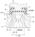
そこで、図27に示すように、メタルシール弁部90xよりも燃料流れ上流側に、一方のシート部がゴムなどの弾性材にて構成された弾性シール弁部91xを設けて、シール性の向上を図った燃料噴射弁が提案されている(例えば、先述した特許文献3参照)。   Therefore, as shown in FIG. 27, an elastic seal valve portion 91x in which one seat portion is made of an elastic material such as rubber is provided upstream of the metal seal valve portion 90x to improve the sealing performance. Has been proposed (see, for example, Patent Document 3 described above).

しかしながら、従来の燃料噴射弁は、メタルシール弁部90xのセット荷重および弾性シール弁部91xのセット荷重を高精度に管理するためには、閉弁時の弾性材の変形量を厳密に管理する必要があり、そのためには、ボデー92xの2つのシート部間の距離L1x、および弁体93xの2つのシート部間の距離L2xを、厳密に管理する必要があった。したがって、ボデー92xや弁体93xを高精度に加工する必要があった。   However, in the conventional fuel injection valve, in order to manage the set load of the metal seal valve portion 90x and the set load of the elastic seal valve portion 91x with high accuracy, the deformation amount of the elastic material when the valve is closed is strictly managed. For this purpose, it is necessary to strictly manage the distance L1x between the two seat portions of the body 92x and the distance L2x between the two seat portions of the valve body 93x. Therefore, it is necessary to process the body 92x and the valve body 93x with high accuracy.

第2の発明は上記点に鑑みて、ボデーや弁体の高精度な加工を必要とせず、メタルシール弁部のセット荷重および弾性シール弁部のセット荷重を容易に高精度に管理可能にすることを目的とする。   In view of the above points, the second invention makes it possible to easily and accurately manage the set load of the metal seal valve portion and the set load of the elastic seal valve portion without requiring high-precision processing of the body or the valve body. For the purpose.

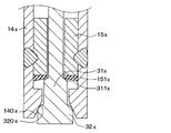
上記目的を達成するため、第2の発明では、往復動する金属製の可動部(3x、4x)に、上流側可動シート部(40x、310x、311x)が設けられるとともに上流側可動シート部(40x、310x、311x)よりも燃料流れ下流側に下流側可動シート部(320x)が設けられ、金属製のボデー(1x)に、上流側ボデーシート部(141x、150x、151x)が設けられるとともに上流側ボデーシート部(141x、150x、151x)よりも燃料流れ下流側に下流側ボデーシート部(140x、152x)が設けられ、上流側可動シート部(40x、310x、311x)および上流側ボデーシート部(141x、150x、151x)のうちいずれか一方、或いは、前記下流側可動シート部(320x)および前記下流側ボデーシート部(140x、152x)のうちいずれか一方は、金属よりも弾性に富む弾性材にて構成され、上流側可動シート部(40x、310x、311x)と上流側ボデーシート部(141x、150x、151x)との接離により燃料通路を開閉するとともに、下流側可動シート部(320x)と下流側ボデーシート部(140x、152x)との接離により燃料通路を開閉し、開弁時に燃料を内燃機関に噴射する燃料噴射弁であって、可動部(3x、4x)は、スプリング(5x)により閉弁向きに付勢されており、ボデー(1x)は、上流側ボデーシート部(141x、150x、151x)が設けられた第1ボデー(14Ax、15x)と、下流側ボデーシート部(140x、152x)が設けられた第2ボデー(14x、15Ax)とを備え、第1ボデー(14Ax、15x)と第2ボデー(14x、15Ax)は別体に形成された後に一体化されていることを特徴とする。   In order to achieve the above object, according to the second aspect of the present invention, the upstream movable sheet portion (40x, 310x, 311x) is provided on the reciprocating metal movable portion (3x, 4x) and the upstream movable sheet portion ( 40x, 310x, 311x), a downstream movable seat portion (320x) is provided downstream of the fuel flow, and a metal body (1x) is provided with upstream body seat portions (141x, 150x, 151x). A downstream body seat portion (140x, 152x) is provided on the downstream side of the fuel flow from the upstream body seat portion (141x, 150x, 151x), and the upstream movable seat portion (40x, 310x, 311x) and the upstream body seat Part (141x, 150x, 151x), or the downstream movable sheet part (320x) and the Any one of the flow side body sheet portions (140x, 152x) is made of an elastic material richer in elasticity than the metal, and includes an upstream movable sheet portion (40x, 310x, 311x) and an upstream body sheet portion (141x). , 150x, 151x), the fuel passage is opened and closed, and the fuel passage is opened and closed by the contact between the downstream movable seat portion (320x) and the downstream body seat portion (140x, 152x). A fuel injection valve for injecting fuel into an internal combustion engine, wherein the movable portions (3x, 4x) are urged toward the valve closing direction by springs (5x), and the body (1x) has an upstream body seat portion ( 141x, 150x, 151x) provided with a first body (14Ax, 15x) and a downstream body sheet portion (140x, 152x) provided with a second body (14 It comprises 15ax) and the first body (14Ax, 15x) and second body (14x, 15ax) is characterized in that it is integrated after being formed separately.

これによると、組み付け段階において第1ボデー(14Ax、15x)と第2ボデー(14x、15Ax)の相対位置を調整することにより、ボデー(1x)や可動部(3x、4x)を高精度に加工しなくても、上流側可動シート部(40x、310x、311x)と上流側ボデーシート部(141x、150x、151x)とで構成される弾性シール弁部のセット荷重、および下流側可動シート部(320x)と下流側ボデーシート部(140x、152x)とで構成されるメタルシール弁部のセット荷重を、容易に高精度に管理することができる。或いは、下流側可動シート部(320x)と下流側ボデーシート部(140x、152x)とで構成される弾性シール弁部のセット荷重、および上流側可動シート部(40x、310x、311x)と上流側ボデーシート部(141x、150x、151x)とで構成されるメタルシール弁部のセット荷重を、容易に高精度に管理することができる。   According to this, by adjusting the relative positions of the first body (14Ax, 15x) and the second body (14x, 15Ax) in the assembly stage, the body (1x) and the movable part (3x, 4x) are processed with high accuracy. Even if not, the set load of the elastic seal valve portion constituted by the upstream movable seat portion (40x, 310x, 311x) and the upstream body seat portion (141x, 150x, 151x), and the downstream movable seat portion ( 320x) and the set load of the metal seal valve portion composed of the downstream body seat portions (140x, 152x) can be easily managed with high accuracy. Alternatively, the set load of the elastic seal valve portion composed of the downstream movable seat portion (320x) and the downstream body seat portion (140x, 152x), and the upstream movable seat portion (40x, 310x, 311x) and the upstream side The set load of the metal seal valve portion constituted by the body seat portions (141x, 150x, 151x) can be easily managed with high accuracy.

さらに、上記第2の発明に以下の構成を追加することで、下記の効果が発揮される。すなわち、請求項26に記載の発明では、上流側ボデーシート部(150x、151x)および下流側ボデーシート部(140)はテーパ状であり、上流側ボデーシート部(150x、151x)のテーパ角が下流側ボデーシート部(140)のテーパ角よりも大であることを特徴とする。   Furthermore, the following effects are exhibited by adding the following configuration to the second invention. That is, in the invention described in claim 26, the upstream body seat portion (150x, 151x) and the downstream body seat portion (140) are tapered, and the taper angle of the upstream body seat portion (150x, 151x) is It is larger than the taper angle of the downstream body sheet part (140).

これによると、弾性シール弁部のシート径をメタルシール弁部のシート径よりも小さくすることができるため、開弁に必要な力を小さくすることができる。   According to this, since the seat diameter of the elastic seal valve portion can be made smaller than the seat diameter of the metal seal valve portion, the force required for valve opening can be reduced.

請求項27に記載の発明では、上流側可動シート部(40x、310x、311x)と下流側可動シート部(320x)は、可動部(3x、4x)の往復動方向に沿って配置されており、上流側可動シート部(40x、310x、311x)から下流側可動シート部(320x)に向かう向きに可動部(3x、4x)が移動することにより、燃料通路が開かれるように構成されていることを特徴とする。   In the invention of claim 27, the upstream movable sheet portion (40x, 310x, 311x) and the downstream movable sheet portion (320x) are arranged along the reciprocating direction of the movable portion (3x, 4x). The movable portion (3x, 4x) moves in the direction from the upstream movable seat portion (40x, 310x, 311x) toward the downstream movable seat portion (320x), so that the fuel passage is opened. It is characterized by that.

これによると、所謂外開弁にすることができる。   According to this, a so-called outer valve can be formed.

請求項28に記載の発明では、上流側可動シート部(310x)と下流側可動シート部(320x)は、可動部(3x、4x)の往復動方向に沿って配置されており、下流側可動シート部(320x)から上流側可動シート部(310x)に向かう向きに可動部(3x、4x)が移動することにより、燃料通路が開かれるように構成されていることを特徴とする。   In the invention according to Claim 28, the upstream movable sheet portion (310x) and the downstream movable sheet portion (320x) are disposed along the reciprocating direction of the movable portion (3x, 4x), and are movable downstream. The fuel passage is opened by moving the movable portions (3x, 4x) in a direction from the seat portion (320x) toward the upstream movable seat portion (310x).

これによると、所謂内開弁であるため、噴孔を有する燃料噴射弁とすることができる。   According to this, since it is a so-called inner open valve, a fuel injection valve having an injection hole can be obtained.

請求項29に記載の発明では、第1ボデー(14Ax、15x)と第2ボデー(14x、15Ax)は、全周溶接にて一体化されていることを特徴とする。   The invention according to claim 29 is characterized in that the first body (14Ax, 15x) and the second body (14x, 15Ax) are integrated by all-around welding.

これによると、シール部材を用いることなく、第1ボデー(14Ax、15x)と第2ボデー(14x、15Ax)との間をシールすることができる。   According to this, it is possible to seal between the first body (14Ax, 15x) and the second body (14x, 15Ax) without using a seal member.

請求項30に記載の発明では、第1ボデー(14Ax、15x)と第2ボデー(14x、15Ax)は、断続溶接にて一体化され、第1ボデー(14Ax、15x)と第2ボデー(14x、15Ax)との間は、シール部材(8x)にてシールされていることを特徴とする。   In the invention described in claim 30, the first body (14Ax, 15x) and the second body (14x, 15Ax) are integrated by intermittent welding, and the first body (14Ax, 15x) and the second body (14x , 15Ax) is sealed with a sealing member (8x).

これによると、全周溶接する場合よりも溶接コストを低減することができる。   According to this, welding cost can be reduced compared with the case where all-around welding is performed.

請求項31に記載の発明では、スプリング(5x)はコイルスプリングであり、可動部(3x、4x)は、スプリング(5x)内を貫通して配置され、上流側可動シート部(40x、310x)は、スプリング(5x)よりも燃料流れ上流側に配置され、下流側可動シート部(320x)は、スプリング(5x)よりも燃料流れ下流側に配置されていることを特徴とする。   In the invention of claim 31, the spring (5x) is a coil spring, and the movable portions (3x, 4x) are disposed through the spring (5x), and the upstream movable seat portion (40x, 310x). Is arranged on the upstream side of the fuel flow from the spring (5x), and the downstream movable seat part (320x) is arranged on the downstream side of the fuel flow from the spring (5x).

ところで、燃料噴射弁を直噴用として用いた場合、高温の燃焼ガスの熱により弾性材にて構成されたシート部が溶損してしまう虞があるが、請求項31に記載の発明によれば、弾性材にて構成されたシート部を燃焼ガスの熱を受ける部位から遠ざけることができるため、そのシート部の溶損を防止することができる。   By the way, when the fuel injection valve is used for direct injection, there is a risk that the seat portion made of the elastic material may be melted by the heat of the high-temperature combustion gas. Since the sheet portion made of the elastic material can be moved away from the portion that receives the heat of the combustion gas, the sheet portion can be prevented from being melted.

請求項32に記載の発明のように、上流側可動シート部(40x、310x)を弾性材にて構成することができる。   As in the invention of the thirty-second aspect, the upstream side movable sheet portion (40x, 310x) can be made of an elastic material.

請求項33に記載の発明のように、上流側ボデーシート部(151x)を弾性材にて構成することができる。   As in the invention described in claim 33, the upstream body sheet portion (151x) can be made of an elastic material.

請求項34に記載の発明のように、燃料は気体燃料を用いることができる。   As in the 34th aspect of the invention, gaseous fuel can be used.

なお、特許請求の範囲および上記手段の項に記載した括弧内の符号は、ひとつの態様として後述する実施形態に記載の具体的手段との対応関係を示すものであって、本発明の技術的範囲を限定するものではない。   Note that the reference numerals in parentheses described in the claims and the above-described means indicate the correspondence with the specific means described in the embodiments described later as one aspect, and are technical terms of the present invention. It does not limit the range.

本発明の第1実施形態による燃料噴射弁の構成を示す断面図であって、図4に示すI−I線の断面図である。It is sectional drawing which shows the structure of the fuel injection valve by 1st Embodiment of this invention, Comprising: It is sectional drawing of the II line | wire shown in FIG. 本発明の第1実施形態による燃料噴射弁の構成を示す断面図であって、図4に示すII−II線の断面図である。It is sectional drawing which shows the structure of the fuel injection valve by 1st Embodiment of this invention, Comprising: It is sectional drawing of the II-II line | wire shown in FIG. 本発明の第1実施形態による燃料噴射弁の構成を拡大して示す断面図である。It is sectional drawing which expands and shows the structure of the fuel injection valve by 1st Embodiment of this invention. 本発明の第1実施形態による燃料噴射弁の構成を示す断面図であって、図1に示すIV−IV線の断面図である。It is sectional drawing which shows the structure of the fuel injection valve by 1st Embodiment of this invention, Comprising: It is sectional drawing of the IV-IV line | wire shown in FIG. 本発明の第1実施形態による燃料噴射弁の構成を示す断面図であって、図1に示すV−V線の断面図である。It is sectional drawing which shows the structure of the fuel injection valve by 1st Embodiment of this invention, Comprising: It is sectional drawing of the VV line shown in FIG. 本発明の第1実施形態による燃料噴射弁の噴孔付近の燃料流れの様子を示す図である。It is a figure which shows the mode of the fuel flow near the nozzle hole of the fuel injection valve by 1st Embodiment of this invention. 本発明の第2実施形態による燃料噴射弁の構成を拡大して示す断面図である。It is sectional drawing which expands and shows the structure of the fuel injection valve by 2nd Embodiment of this invention. 本発明の第3実施形態による燃料噴射弁の構成を拡大して示す断面図である。It is sectional drawing which expands and shows the structure of the fuel injection valve by 3rd Embodiment of this invention. 本発明の第4実施形態による燃料噴射弁の構成を拡大して示す断面図である。It is sectional drawing which expands and shows the structure of the fuel injection valve by 4th Embodiment of this invention. 本発明の第5実施形態による燃料噴射弁の構成を示す断面図である。It is sectional drawing which shows the structure of the fuel injection valve by 5th Embodiment of this invention. 本発明の第5実施形態による燃料噴射弁の構成を拡大して示す断面図である。It is sectional drawing which expands and shows the structure of the fuel injection valve by 5th Embodiment of this invention. 本発明の第6実施形態による燃料噴射弁の構成を拡大して示す断面図である。It is sectional drawing which expands and shows the structure of the fuel injection valve by 6th Embodiment of this invention. 本発明の第7実施形態による燃料噴射弁の構成を拡大して示す断面図である。It is sectional drawing which expands and shows the structure of the fuel injection valve by 7th Embodiment of this invention. 本発明の第8実施形態による燃料噴射弁の構成を拡大して示す断面図である。It is sectional drawing which expands and shows the structure of the fuel injection valve by 8th Embodiment of this invention. 本発明の第9実施形態に係る燃料噴射弁を示す断面図である。It is sectional drawing which shows the fuel injection valve which concerns on 9th Embodiment of this invention. 第9実施形態の第1変形例を示す断面図である。It is sectional drawing which shows the 1st modification of 9th Embodiment. 第9実施形態の第2変形例を示す断面図である。It is sectional drawing which shows the 2nd modification of 9th Embodiment. 本発明の第10実施形態に係る燃料噴射弁を示す断面図である。It is sectional drawing which shows the fuel injection valve which concerns on 10th Embodiment of this invention. 第10実施形態の第1変形例を示す断面図である。It is sectional drawing which shows the 1st modification of 10th Embodiment. 本発明の第11実施形態に係る燃料噴射弁を示す断面図である。It is sectional drawing which shows the fuel injection valve which concerns on 11th Embodiment of this invention. 本発明の第12実施形態に係る燃料噴射弁を示す断面図である。It is sectional drawing which shows the fuel injection valve which concerns on 12th Embodiment of this invention. 本発明の第13実施形態に係る燃料噴射弁を示す断面図である。It is sectional drawing which shows the fuel injection valve which concerns on 13th Embodiment of this invention. 第13実施形態に係る燃料噴射弁の作動を示すタイムチャート。A time chart which shows operation of a fuel injection valve concerning a 13th embodiment. 第13実施形態において、電磁力による吸引力とギャップとの関係を示す試験結果。In 13th Embodiment, the test result which shows the relationship between the attraction | suction force by an electromagnetic force, and a gap. 本発明の第14実施形態に係る燃料噴射弁を示す断面図である。It is sectional drawing which shows the fuel injection valve which concerns on 14th Embodiment of this invention. 第14実施形態の変形例を示す断面図である。It is sectional drawing which shows the modification of 14th Embodiment. 従来の燃料噴射弁を示す要部の断面図である。It is sectional drawing of the principal part which shows the conventional fuel injection valve.

(第1実施形態)
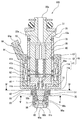
図1に示す燃料噴射弁100は、内燃機関としてのエンジンに設置され、当該エンジンの燃焼室にCNG(Compressed Natural Gas)、LNG(Liquefied Natural Gas)、水素等のガス燃料を噴射する。以下、燃料噴射弁100の構成について、図1〜図6を用いて説明する。燃料噴射弁100は、ハウジング10、入口部材20、固定コア30、可動コア40、弁体50、ノズル部材60、ストッパ70、及び駆動装置90等を備えている。
(First embodiment)
A fuel injection valve 100 shown in FIG. 1 is installed in an engine as an internal combustion engine, and injects gas fuel such as CNG (Compressed Natural Gas), LNG (Liquefied Natural Gas), and hydrogen into a combustion chamber of the engine. Hereinafter, the configuration of the fuel injection valve 100 will be described with reference to FIGS. The fuel injection valve 100 includes a housing 10, an inlet member 20, a fixed core 30, a movable core 40, a valve body 50, a nozzle member 60, a stopper 70, a driving device 90, and the like.

ハウジング10は、全体として筒状に形成されており、軸方向の両端部が開口している。ハウジング10において軸方向の一端部側から他端部側に向かって順に第1磁性部11、非磁性部12、及び第2磁性部13を有している。磁性体として機能するフェライト系ステンレス鋼からなる第1、第2磁性部11、13と、非磁性体として機能するオーステナイト系ステンレス鋼からなる非磁性部12とは、レーザ溶接等により結合されている。かかる結合形態によって非磁性部12は、第1磁性部11及び第2磁性部13の間で磁束が短絡するのを防止する。   The housing 10 is formed in a cylindrical shape as a whole, and both ends in the axial direction are open. The housing 10 has a first magnetic part 11, a nonmagnetic part 12, and a second magnetic part 13 in order from one end side in the axial direction toward the other end side. The first and second magnetic parts 11 and 13 made of ferritic stainless steel functioning as a magnetic body and the nonmagnetic part 12 made of austenitic stainless steel functioning as a nonmagnetic material are coupled by laser welding or the like. . The nonmagnetic part 12 prevents the magnetic flux from being short-circuited between the first magnetic part 11 and the second magnetic part 13 by such a coupling form.

第1磁性部11は、非磁性部12と結合される大径部11dと、大径部11dよりも外径が小さい小径部11aとを有している。小径部11aにおいて非磁性部12とは反対側の端部、即ちハウジング10内での燃料流れにおいて下流側の端部に形成されている開口部11cには、ノズル部材60が設けられている。また、ハウジング10の軸方向における一方の端部と他方の端部との間には、ストッパ70が設けられている。さらに、第2磁性部13において非磁性部12とは反対側の端部13aには、入口部材20が設けられている。   The first magnetic part 11 has a large diameter part 11d coupled to the nonmagnetic part 12, and a small diameter part 11a having an outer diameter smaller than that of the large diameter part 11d. A nozzle member 60 is provided at an end portion of the small diameter portion 11 a opposite to the nonmagnetic portion 12, that is, an opening portion 11 c formed at the downstream end portion in the fuel flow in the housing 10. A stopper 70 is provided between one end and the other end of the housing 10 in the axial direction. Further, an inlet member 20 is provided at the end 13 a of the second magnetic part 13 on the side opposite to the nonmagnetic part 12.

入口部材20は、円筒状に形成されており、燃料ポンプから燃料配管を通じて供給される燃料が燃料噴射弁100に流入されるように、流入口20aを径方向中央部に形成している。入口部材20は、レーザ溶接等により第2磁性部13の端部13aに結合され、固定されている。   The inlet member 20 is formed in a cylindrical shape, and an inflow port 20a is formed in the central portion in the radial direction so that the fuel supplied from the fuel pump through the fuel pipe flows into the fuel injection valve 100. The inlet member 20 is coupled and fixed to the end portion 13a of the second magnetic portion 13 by laser welding or the like.

固定コア30は、磁性体として機能するフェライト系ステンレス鋼によって円筒状に形成されており、非磁性部12及び第2磁性部13の内周壁に同軸上に固定されている。固定コア30には、その径方向中央部を軸方向に貫通する収容孔31が形成されている。収容孔31の内周側には、コイルスプリングからなる付勢部材としてのスプリング80が弾性変形可能に収容されているとともに、スプリング80のセット荷重を調整するためのアジャスティングパイプ32が圧入によって固定されている。スプリング80の一方の端部は、アジャスティングパイプ32に支持されている。アジャスティングパイプ32は、円筒状に形成されており、その径方向中央部を軸方向に貫通する貫通孔32aが形成されている。ここまでの構成によれば、入口部材20より流入した燃料は、収容孔31に流入する。そして、収容孔31に流入した燃料は、貫通孔32aを通って、固定コア30におけるノズル部材60側の端部より排出される。   The fixed core 30 is formed in a cylindrical shape from ferritic stainless steel that functions as a magnetic body, and is fixed coaxially to the inner peripheral walls of the nonmagnetic portion 12 and the second magnetic portion 13. The fixed core 30 is formed with an accommodation hole 31 that penetrates the central portion in the radial direction in the axial direction. A spring 80 as a biasing member made of a coil spring is accommodated on the inner peripheral side of the accommodation hole 31 so as to be elastically deformable, and an adjusting pipe 32 for adjusting the set load of the spring 80 is fixed by press fitting. Has been. One end of the spring 80 is supported by the adjusting pipe 32. The adjusting pipe 32 is formed in a cylindrical shape, and is formed with a through hole 32a that penetrates the central portion in the radial direction in the axial direction. According to the configuration so far, the fuel that has flowed from the inlet member 20 flows into the accommodation hole 31. The fuel that has flowed into the accommodation hole 31 passes through the through hole 32a and is discharged from the end of the fixed core 30 on the nozzle member 60 side.

可動コア40は、磁性体として機能するフェライト系ステンレス鋼によって全体として円筒状に形成されており、ハウジング10の内周側に同軸上に収容されて、固定コア30よりもノズル部材60側に位置している。   The movable core 40 is formed in a cylindrical shape as a whole by ferritic stainless steel functioning as a magnetic body, is coaxially accommodated on the inner peripheral side of the housing 10, and is positioned closer to the nozzle member 60 than the fixed core 30. doing.

可動コア40は、円筒状に形成されたコア本体部41を有している。コア本体部41の外周壁には、第1磁性部11の大径部11d及び非磁性部12の各内周壁に案内される案内部41aが形成されている。ここまでの構成によれば、可動コア40は、案内部41aが大径部11d及び非磁性部12の各内周壁に案内されることで、軸方向に沿って往復移動が可能となる。   The movable core 40 has a core body portion 41 formed in a cylindrical shape. On the outer peripheral wall of the core main body portion 41, a guide portion 41 a that is guided to the inner peripheral wall of the large-diameter portion 11 d of the first magnetic portion 11 and the nonmagnetic portion 12 is formed. According to the configuration so far, the movable core 40 can reciprocate along the axial direction by the guide portion 41a being guided by the inner peripheral walls of the large diameter portion 11d and the nonmagnetic portion 12.

また、コア本体部41において固定コア30側の端部には、その径方向中央部にスプリング80のノズル部材60側の端部を支持する座部41bが形成されている。これにより、可動コア40は、スプリング80のセット荷重に応じたノズル部材60方向への付勢力が常に付与されることとなる。   In addition, a seat 41b that supports the end of the spring 80 on the nozzle member 60 side is formed at the end of the core body 41 on the side of the fixed core 30 at the center in the radial direction. Thereby, the movable core 40 is always given a biasing force in the direction of the nozzle member 60 according to the set load of the spring 80.

さらに、コア本体部41には、その径方向中央部を軸方向に貫通する貫通孔41cが形成されている。この貫通孔41cによれば、収容孔31を介して固定コア30のノズル部材60側に排出された燃料が、貫通孔41cを介して、可動コア40においてノズル部材60側に流れる。   Further, the core main body 41 is formed with a through hole 41c that penetrates the central portion in the radial direction in the axial direction. According to this through hole 41c, the fuel discharged to the nozzle member 60 side of the fixed core 30 through the accommodation hole 31 flows to the nozzle member 60 side in the movable core 40 through the through hole 41c.

可動コア40は、コア本体部41からノズル部材60側に突出する円筒状の収容部42をコア本体部41の貫通孔41cと同軸上に有する。また、収容部42は、後に説明する弁体50の連結部55の一部を収容する。連結部55は、レーザ溶接等により収容部42結合され、固定されている。これにより、可動コア40の軸方向往復移動に伴い、弁体50も可動コア40と一体となって軸方向に沿って往復移動する。   The movable core 40 has a cylindrical accommodating portion 42 that protrudes from the core main body portion 41 toward the nozzle member 60 and is coaxial with the through hole 41 c of the core main body portion 41. Moreover, the accommodating part 42 accommodates a part of connection part 55 of the valve body 50 demonstrated later. The connecting portion 55 is coupled and fixed to the housing portion 42 by laser welding or the like. As a result, as the movable core 40 reciprocates in the axial direction, the valve body 50 also reciprocates along the axial direction together with the movable core 40.

弁体50は、全体として棒状に形成されており、第1磁性部11の内周側に同軸上に収容されて、可動コア40よりもノズル部材60側に位置している。弁体50は、軸方向に沿う往復移動によって、後に説明するノズル部材60に形成されている燃料通路60aを開閉し、噴孔60bから燃焼室への燃料噴射を断続する。   The valve body 50 is formed in a rod shape as a whole, is coaxially accommodated on the inner peripheral side of the first magnetic portion 11, and is positioned closer to the nozzle member 60 than the movable core 40. By reciprocating along the axial direction, the valve body 50 opens and closes a fuel passage 60a formed in a nozzle member 60, which will be described later, and intermittently injects fuel from the injection hole 60b into the combustion chamber.

図3に示すように、弁体50は、可動コア40と連結される弁本体部51を有している。弁本体部51は、非磁性体として機能するマルテンサイト系ステンレス鋼によって棒状に形成されている。弁本体部51は、可動コア40と連結される棒状の連結部55と、連結部55よりもノズル部材60側に位置し、後に説明する弾性部56が取り付けられ、弾性部56を支持する支持部52とを有している。   As shown in FIG. 3, the valve body 50 has a valve body 51 that is connected to the movable core 40. The valve body 51 is formed in a rod shape from martensitic stainless steel that functions as a non-magnetic material. The valve body 51 is positioned on the nozzle member 60 side of the rod-like connecting portion 55 connected to the movable core 40 and the connecting portion 55, and an elastic portion 56 described later is attached to support the elastic portion 56. Part 52.

連結部55には、可動コア40の貫通孔41c内の空間と、連結部55の外周側であって可動コア40及び支持部52間の空間と連通する燃料通路55aが形成されている。これにより、貫通孔41cを通じて燃料通路55aに流入した燃料は、連結部55の外周側であって可動コア40と支持部52との間の空間に排出される。   The connecting portion 55 is formed with a fuel passage 55 a that communicates with the space in the through hole 41 c of the movable core 40 and the space between the movable core 40 and the support portion 52 on the outer peripheral side of the connecting portion 55. As a result, the fuel that has flowed into the fuel passage 55 a through the through hole 41 c is discharged to the space between the movable core 40 and the support portion 52 on the outer peripheral side of the connecting portion 55.

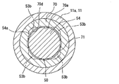
支持部52は、連結部55側に位置する四角柱部53と、四角柱部53よりもノズル部材60側に位置する円柱部54とを有する。四角柱部53の側面において角部には、第1磁性部11の小径部11aと同軸上に設けられたストッパ70の内周壁に案内される案内部53aが形成されている。これにより、弁体50は、案内部53aがストッパ70の内周壁に案内されることで、軸方向に沿って往復移動が可能となる。また、四角柱部53のノズル部材60側の底面における角部には、弁体50がノズル部材60側に移動することにより、後に説明するストッパ70と当接する当接面53bが形成されている。当接面53bがストッパ70に当接することにより、弁体50のノズル部材60側への移動、即ち弁体50の閉塞方向への移動が規制される。なお、当接面53bは、図1〜図3に示すように、ノズル部材60に向かって傾斜している。   The support portion 52 includes a rectangular column portion 53 positioned on the connection portion 55 side, and a columnar portion 54 positioned on the nozzle member 60 side relative to the square column portion 53. A guide portion 53 a that is guided by an inner peripheral wall of a stopper 70 that is provided coaxially with the small diameter portion 11 a of the first magnetic portion 11 is formed on the side surface of the quadrangular column portion 53. Thereby, the valve body 50 can be reciprocated along the axial direction by the guide portion 53 a being guided by the inner peripheral wall of the stopper 70. In addition, a contact surface 53b that comes into contact with a stopper 70, which will be described later, is formed at a corner portion of the bottom surface of the rectangular column portion 53 on the nozzle member 60 side by moving the valve body 50 toward the nozzle member 60 side. . When the contact surface 53b contacts the stopper 70, the movement of the valve body 50 toward the nozzle member 60, that is, the movement of the valve body 50 in the closing direction is restricted. The contact surface 53b is inclined toward the nozzle member 60 as shown in FIGS.

円柱部54について、その断面形状は、四角柱部53の軸方向と交差する方向の断面形状に対して内接するような形状となっている。また、円柱部54の直径は、ストッパ70の内周壁との間に燃料の通過が可能な程度の大きさとなっている。   The cylindrical portion 54 has a cross-sectional shape that is inscribed in a cross-sectional shape in a direction that intersects the axial direction of the quadrangular prism portion 53. Further, the diameter of the cylindrical portion 54 is large enough to allow fuel to pass between the cylindrical portion 54 and the inner peripheral wall of the stopper 70.

さらに円柱部54のノズル部材60側の端部には、円盤状に形成され、ノズル部材60と対向する位置にシート部56aを形成する弾性部56が取り付けられている。この弾性部56は、弁体50のノズル部材60への離着座により弾性変形可能な弾性部材からなっている。本実施形態では、弾性部56は、耐低温性、耐油性に優れるフッ素系ゴムよりなっている。燃料としてガス燃料を使用する場合、燃料噴射の際、噴孔60b付近の圧力が低下するため、噴孔60b付近の温度が約−30℃〜−40℃となることがある。弾性部56としてのフッ素系ゴムはこういった極低温の環境に対しても弾性変形が可能な材料であり、シール性を確保することができる。弾性部56は、インサート成形により円柱部54のノズル部材60側の端部に取り付けられている。   Further, an elastic portion 56 that is formed in a disk shape and forms a sheet portion 56 a is attached to an end portion of the cylindrical portion 54 on the nozzle member 60 side at a position facing the nozzle member 60. The elastic portion 56 is made of an elastic member that can be elastically deformed by the seating of the valve body 50 on the nozzle member 60. In the present embodiment, the elastic portion 56 is made of a fluorinated rubber having excellent low temperature resistance and oil resistance. When gas fuel is used as the fuel, the pressure near the nozzle hole 60b decreases during fuel injection, and the temperature near the nozzle hole 60b may be about −30 ° C. to −40 ° C. The fluorinated rubber as the elastic portion 56 is a material that can be elastically deformed even in such an extremely low temperature environment, and can secure a sealing property. The elastic portion 56 is attached to the end portion of the cylindrical portion 54 on the nozzle member 60 side by insert molding.

また、円柱部54の外周面には、弁体50の往復移動方向に対して交差する方向に凹む溝部が形成されている。一方、弾性部56は、その周縁部に円柱部54の溝部に食い込むようにして配置されるアンカー部56fを形成している。これにより、弾性部56は、支持部52に対して強固に固定される。特に、弁体50の往復移動方向に対する固定強度が増す。   In addition, a groove that is recessed in a direction intersecting the reciprocating direction of the valve body 50 is formed on the outer peripheral surface of the cylindrical portion 54. On the other hand, the elastic part 56 forms an anchor part 56f arranged so as to bite into the groove part of the cylindrical part 54 at the peripheral part. Thereby, the elastic part 56 is firmly fixed to the support part 52. In particular, the fixing strength of the valve body 50 in the reciprocating direction increases.

さらに、弾性部56のノズル部材60と対向する面には、当該面の外周側においてノズル部材60側に突出する環状のシート部56aが形成されるとともに、当該シート部56aの内周側にノズル部材60とは反対側に凹む凹部56bが形成されている。凹部56bの底面56cの周縁に形成される内周面56dにおける径は、ノズル部材60の燃料通路60aにおける弁体50側の開口部60dの径よりも大きい。内周面56dの径は、弾性部56の外径の範囲で設定することができる。シート部56aは、弾性部56のノズル部材60と対向する面において、凹部56bの外周側に形成される。また、内周面56dのノズル部材60側の角部56eは、開口部60dの外周側を囲むように当接可能となる。即ち、シート部56aが開口部60dの外周側を囲むように当接可能となっている。これにより、燃料通路60aが閉塞される。さらに、凹部56bの内周面56dは、凹部56bの径方向中央部に向かうに従い、凹部56bの深さが徐々に深くなるように傾斜している。   Furthermore, an annular sheet portion 56a that protrudes toward the nozzle member 60 is formed on the outer peripheral side of the surface on the surface of the elastic portion 56 that faces the nozzle member 60, and a nozzle is formed on the inner peripheral side of the sheet portion 56a. A recess 56b is formed on the opposite side of the member 60. The diameter of the inner peripheral surface 56 d formed on the periphery of the bottom surface 56 c of the recess 56 b is larger than the diameter of the opening 60 d on the valve body 50 side in the fuel passage 60 a of the nozzle member 60. The diameter of the inner peripheral surface 56d can be set within the range of the outer diameter of the elastic portion 56. The sheet portion 56a is formed on the outer peripheral side of the recess 56b on the surface of the elastic portion 56 facing the nozzle member 60. Further, the corner 56e of the inner peripheral surface 56d on the nozzle member 60 side can come into contact so as to surround the outer peripheral side of the opening 60d. That is, the sheet portion 56a can come into contact with the outer peripheral side of the opening 60d. As a result, the fuel passage 60a is closed. Furthermore, the inner peripheral surface 56d of the concave portion 56b is inclined so that the depth of the concave portion 56b gradually becomes deeper toward the central portion in the radial direction of the concave portion 56b.

ノズル部材60は、非磁性体として機能するマルテンサイト系ステンレス鋼によって円筒状に形成され、径方向中央部を軸方向に貫通する燃料通路60aを形成している。また、本実施形態では、ノズル部材60は、ハウジング10及びストッパ70とは異なる部材によって形成されている。ノズル部材60は、第1磁性部11の小径部11aの一方の端部に形成されている開口部11cから挿入され、レーザ溶接等により開口部11cに結合され、固定されている。ノズル部材60の弁体50側の端面において燃料通路60aの開口部の周縁部には、シート部56aが離着座可能な弁座部60cが形成されている。また、燃料通路60aにおいて弁体50とは反対側の端部は、燃料が噴射される噴孔60bとなっている。   The nozzle member 60 is formed in a cylindrical shape by martensitic stainless steel functioning as a non-magnetic material, and forms a fuel passage 60a penetrating the radial center in the axial direction. In the present embodiment, the nozzle member 60 is formed of a member different from the housing 10 and the stopper 70. The nozzle member 60 is inserted from an opening 11c formed at one end of the small diameter part 11a of the first magnetic part 11, and is coupled and fixed to the opening 11c by laser welding or the like. A valve seat portion 60c on which the seat portion 56a can be attached and detached is formed on the peripheral portion of the opening portion of the fuel passage 60a on the end surface of the nozzle member 60 on the valve body 50 side. Further, the end of the fuel passage 60a opposite to the valve body 50 is an injection hole 60b through which fuel is injected.

シート部56aは、図1に示すように弁座部60cに着座させる閉塞作動により、燃料通路60aを閉塞する。これにより、噴孔60bへの燃料の流通が停止する。このとき、弾性部56は、弁体50の移動量に応じて弾性変形する。一方、シート部56aは、図2に示すように弁座部60cから離座させる開放作動により、燃料通路60aを開放する。これにより、噴孔60bへの燃料の流通が許容される。   As shown in FIG. 1, the seat portion 56a closes the fuel passage 60a by a closing operation for seating on the valve seat portion 60c. As a result, the fuel flow to the nozzle hole 60b is stopped. At this time, the elastic portion 56 is elastically deformed according to the movement amount of the valve body 50. On the other hand, the seat portion 56a opens the fuel passage 60a by an opening operation in which the seat portion 56a is separated from the valve seat portion 60c as shown in FIG. Thereby, the flow of fuel to the nozzle hole 60b is allowed.

ストッパ70は、非磁性体として機能するマルテンサイト系ステンレス鋼によって円筒状に形成され、径方向中央部に弁体50の支持部52を収容する収容孔70aを形成している。また、本実施形態では、ストッパ70は、ハウジング10とは異なる部材によって形成されている。   The stopper 70 is formed in a cylindrical shape by martensitic stainless steel functioning as a non-magnetic material, and an accommodation hole 70a for accommodating the support portion 52 of the valve body 50 is formed in the central portion in the radial direction. In the present embodiment, the stopper 70 is formed of a member different from the housing 10.

ストッパ70は、可動コア40側の端面70bを小径部11aの内周壁に形成されている段差部11bに突き当てた状態で、ハウジング10に対して位置決めされている。ストッパ70は、ハウジング10に位置決めされた状態で、レーザ溶接等により小径部11aに結合され、固定されている。軸方向と交差する方向の断面形状が円形となる収容孔70aは、可動コア40側の第1内周面70cを形成するとともに、ノズル部材60側に第1内周面70cの部位よりも内径が小さい第2内周面70dを形成する。   The stopper 70 is positioned with respect to the housing 10 in a state where the end surface 70b on the movable core 40 side is abutted against the step portion 11b formed on the inner peripheral wall of the small diameter portion 11a. The stopper 70 is coupled and fixed to the small diameter portion 11a by laser welding or the like while being positioned in the housing 10. The housing hole 70a having a circular cross-sectional shape in the direction intersecting the axial direction forms the first inner peripheral surface 70c on the movable core 40 side, and has an inner diameter that is closer to the nozzle member 60 side than the portion of the first inner peripheral surface 70c. The second inner peripheral surface 70d having a small height is formed.

図3及び図4に示すように、第1内周面70cの内周側には、弁体50の四角柱部53が収容され、第1内周面70cは、四角柱部53の外周面53cにおいて四隅に設けられる案内部53aを全て案内する。また、図3及び図5に示すように、第2内周面70dの内周側には、弁体50の円柱部54及び弾性部56が収容される。第2内周面70dの部位の径は、円柱部54の外周面54aとの間に燃料をノズル部材60に流通可能な隙間が形成される程に設定されている。また、軸方向と交差する方向において、第1内周面70cの部位が円形となり、四角柱部53が四角状となっていることから、四角柱部53の外周面53cにおいて案内部53aを除く部位と第1内周面70cとの間に隙間が形成され、円柱部54の外周面54aと第2内周面70dとの間に隙間が形成される。これらの隙間は、互いに連通している。また、これらの弁体50の外周面とストッパ70の内周面との間の隙間は、後で説明するストッパ70のテーパ面70eが弁体50の当接面53bが当接した状態であっても区画されており、燃料通路71として機能する。燃料通路71は、連結部55の燃料通路55aとも常に連通しており、連結部55の外周側に排出された燃料の流れを許容し、その燃料をノズル部材60まで導く。   As shown in FIGS. 3 and 4, the rectangular column portion 53 of the valve body 50 is accommodated on the inner peripheral side of the first inner peripheral surface 70 c, and the first inner peripheral surface 70 c is the outer peripheral surface of the quadrangular column portion 53. In 53c, all the guide parts 53a provided at the four corners are guided. As shown in FIGS. 3 and 5, the cylindrical portion 54 and the elastic portion 56 of the valve body 50 are accommodated on the inner peripheral side of the second inner peripheral surface 70 d. The diameter of the portion of the second inner peripheral surface 70d is set such that a gap is formed between the outer peripheral surface 54a of the cylindrical portion 54 so that fuel can flow to the nozzle member 60. Further, in the direction intersecting with the axial direction, the portion of the first inner peripheral surface 70c is circular and the quadrangular column portion 53 is quadrangular, so the guide portion 53a is excluded from the outer peripheral surface 53c of the quadrangular column portion 53. A gap is formed between the part and the first inner peripheral surface 70c, and a gap is formed between the outer peripheral surface 54a of the cylindrical portion 54 and the second inner peripheral surface 70d. These gaps communicate with each other. Further, the gap between the outer peripheral surface of the valve body 50 and the inner peripheral surface of the stopper 70 is a state where a tapered surface 70e of the stopper 70 described later is in contact with the contact surface 53b of the valve body 50. However, it is also partitioned and functions as the fuel passage 71. The fuel passage 71 always communicates with the fuel passage 55 a of the connecting portion 55, allows the flow of fuel discharged to the outer peripheral side of the connecting portion 55, and guides the fuel to the nozzle member 60.

さらに、収容孔70aは、第1内周面70c及び第2内周面70dとの間に、弁体50の当接面53bと当接可能なテーパ面70eを形成している。テーパ面70eは、環状に形成されており、可動コア40側からノズル部材60側に向かうほど径が小さくなるように傾斜している。テーパ面70eは、当接面53bと当接することにより、弁体50の閉塞方向への移動を規制する。また、テーパ面70eは、弁体50の移動方向に沿った方向において、弾性部56がノズル部材60の弁座部60cに着座して弾性変形し、弾性部56の潰れ代が所定の値となる位置に設けられている。ここで、所定の値とは、弾性部56の圧縮永久歪による破損を防止しつつ、弁体50のストローク変化を抑えられる値に設定される。ここで、所定の値とは、圧縮による弾性材56の損傷を防止しつつ、弾性部56の圧縮永久歪や幾何公差による傾きが発生した場合でも燃料通路60aを閉塞できる値に設定される。例えば、所定の値は、弾性部56の圧縮率が8%から35%の範囲内のうち、弾性部56の圧縮永久歪や幾何公差による傾きが発生した場合でもシールができる最小の値に設定すると良い。   Furthermore, the accommodation hole 70a forms a tapered surface 70e that can contact the contact surface 53b of the valve body 50 between the first inner peripheral surface 70c and the second inner peripheral surface 70d. The taper surface 70e is formed in an annular shape, and is inclined so that the diameter becomes smaller from the movable core 40 side toward the nozzle member 60 side. The taper surface 70e restricts the movement of the valve body 50 in the closing direction by contacting the contact surface 53b. The tapered surface 70e is elastically deformed by the elastic portion 56 seated on the valve seat portion 60c of the nozzle member 60 in the direction along the moving direction of the valve body 50, and the crushing margin of the elastic portion 56 becomes a predetermined value. It is provided in the position. Here, the predetermined value is set to a value that can suppress a change in the stroke of the valve body 50 while preventing the elastic portion 56 from being damaged due to compression set. Here, the predetermined value is set to a value that can block the fuel passage 60a even when the elastic member 56 is prevented from being damaged by compression and the elastic portion 56 is inclined due to compression set or geometric tolerance. For example, the predetermined value is set to the minimum value within which the elastic portion 56 has a compression rate of 8% to 35% so that the elastic portion 56 can be sealed even when an inclination due to compression set or geometric tolerance of the elastic portion 56 occurs. Good.

また、燃料噴射弁100の中心軸とテーパ面とのなす角度としてのテーパ面70eの傾斜角度は、当該中心軸と当接面53bとのなす角度としての当接面53bの傾斜角度よりも小さい。また、ストッパ70に使用する材料は、上述したように弁体50の支持部52に使用する材料と同じとなっている。このため、ストッパ70のテーパ面70eと弁体50の当接面53bとはほぼ同じ硬度となっている。さらに、弁体50の当接面53bには、DLC(ダイアモンドライクカーボン:diamond-like carbon)、又はポリテトラフルオロエチレン(登録商標:テフロン)等の被覆層72が設けられている。なお、被覆層72はストッパ70のテーパ面70eに設けても良いし、弁体50の当接面53bとストッパ70のテーパ面70eとの両方に設けても良い。本実施形態では、被覆層72を当接面53bに設けているので、当接面53bとテーパ面70eとの両方に設ける場合よりも製造コストを下げることができる。また、被覆層72を弁体50の外周面に被覆することによって、ストッパ70の内周面に被覆する場合よりも被覆層72の被覆が容易にできる。   Further, the inclination angle of the tapered surface 70e as an angle formed by the central axis of the fuel injection valve 100 and the tapered surface is smaller than the inclination angle of the contact surface 53b as an angle formed by the central axis and the contact surface 53b. . The material used for the stopper 70 is the same as the material used for the support portion 52 of the valve body 50 as described above. For this reason, the taper surface 70e of the stopper 70 and the contact surface 53b of the valve body 50 have substantially the same hardness. Further, the contact surface 53b of the valve body 50 is provided with a coating layer 72 such as DLC (diamond-like carbon) or polytetrafluoroethylene (registered trademark: Teflon). The covering layer 72 may be provided on the tapered surface 70e of the stopper 70, or may be provided on both the contact surface 53b of the valve body 50 and the tapered surface 70e of the stopper 70. In this embodiment, since the coating layer 72 is provided on the contact surface 53b, the manufacturing cost can be reduced as compared with the case where the cover layer 72 is provided on both the contact surface 53b and the tapered surface 70e. Further, by covering the outer peripheral surface of the valve body 50 with the covering layer 72, the covering layer 72 can be covered more easily than when the inner peripheral surface of the stopper 70 is covered.

ここまでの構成によれば、ストッパ70のテーパ面70eに弁体50の当接面53bが当接した状態では、弾性部56のシート部56aが弁座部60cに着座するので、燃料通路60aが閉塞され、流入口20aから収容孔31、貫通孔32a、貫通孔41c、燃料通路55aを順に介して燃料通路71にまで至った燃料は、噴孔60bから噴射されない。弁体50が可動コア40とともに固定コア30に向かって、弾性部56の潰れ代分を超えて移動すると、シート部56aが弁座部60cから離座するので、燃料通路60aが開放され、燃料通路71に至った燃料が弾性部56とノズル部材60との間の隙間、及び燃料通路60aを介して噴孔60bから噴射される。   According to the configuration so far, in the state where the contact surface 53b of the valve body 50 is in contact with the tapered surface 70e of the stopper 70, the seat portion 56a of the elastic portion 56 is seated on the valve seat portion 60c. The fuel that reaches the fuel passage 71 from the inlet 20a through the accommodation hole 31, the through hole 32a, the through hole 41c, and the fuel passage 55a in this order is not injected from the injection hole 60b. When the valve body 50 moves along with the movable core 40 toward the fixed core 30 beyond the collapse allowance of the elastic portion 56, the seat portion 56a is separated from the valve seat portion 60c, so that the fuel passage 60a is opened, and the fuel The fuel that has reached the passage 71 is injected from the nozzle hole 60b through the gap between the elastic portion 56 and the nozzle member 60 and the fuel passage 60a.

駆動装置90は、図1及び図2に示すように、電磁コイル91、ヨーク92、及びコネクタ93等から構成されている。電磁コイル91は、樹脂製のボビンに金属線材を巻回してなる。電磁コイル91は、ハウジング10の径方向外周側に、同軸上に配置されている。コネクタ93は、外部の制御回路と電磁コイル91との間を電気接続するターミナル93aを有しており、当該制御回路によって電磁コイル91への通電が制御されるようになっている。   As shown in FIGS. 1 and 2, the driving device 90 includes an electromagnetic coil 91, a yoke 92, a connector 93, and the like. The electromagnetic coil 91 is formed by winding a metal wire around a resin bobbin. The electromagnetic coil 91 is coaxially disposed on the radially outer peripheral side of the housing 10. The connector 93 has a terminal 93 a that electrically connects an external control circuit and the electromagnetic coil 91, and energization of the electromagnetic coil 91 is controlled by the control circuit.

ヨーク92は、磁性体として機能するフェライト系ステンレス鋼によって円筒状に形成されており、電磁コイル91及びハウジング10の径方向外周側に配置されて当該電磁コイル91を覆っている。また、ヨーク92は、ノズル部材60側の端部に小径部を形成しており、その小径部は、レーザ溶接等により第1磁性部11の小径部11aに結合され、固定されている。   The yoke 92 is formed in a cylindrical shape from ferritic stainless steel that functions as a magnetic body, and is disposed on the radially outer side of the electromagnetic coil 91 and the housing 10 to cover the electromagnetic coil 91. The yoke 92 has a small diameter portion at the end on the nozzle member 60 side, and the small diameter portion is coupled and fixed to the small diameter portion 11a of the first magnetic portion 11 by laser welding or the like.

ターミナル93aを介して電磁コイル91への電力供給により、電磁コイル91が通電によって励磁すると、ヨーク92、第1磁性部11、可動コア40、固定コア30、及び第2磁性部13が共同して形成される磁気回路に、磁束が流れる。その結果、互いに対向配置されている可動コア40と固定コア30との間に、可動コア40を固定コア30側に吸引して駆動する「磁力」としての磁気吸引力が発生する。一方、通電の停止によって電磁コイル91が消磁すると、磁気回路に磁束が流れなくなるので、可動コア40と固定コア30との間において磁気吸引力が消失する。   When the electromagnetic coil 91 is excited by energization by supplying power to the electromagnetic coil 91 via the terminal 93a, the yoke 92, the first magnetic part 11, the movable core 40, the fixed core 30, and the second magnetic part 13 are jointly operated. Magnetic flux flows through the formed magnetic circuit. As a result, a magnetic attractive force as a “magnetic force” is generated between the movable core 40 and the fixed core 30 facing each other so as to attract and drive the movable core 40 toward the fixed core 30. On the other hand, when the electromagnetic coil 91 is demagnetized by stopping energization, the magnetic flux does not flow in the magnetic circuit, so that the magnetic attractive force disappears between the movable core 40 and the fixed core 30.

以下、燃料噴射弁100の作動について詳細に説明する。燃料噴射弁100において、電磁コイル91への通電が停止している図1に示す状態では、可動コア40に作用する磁気吸引力が消失しているので、可動コア40に付与されるスプリング80の付勢力によって、弁体50の当接面53bがストッパ70のテーパ面70eに押し付けられる。このとき、弾性部56のシート部56aは、弁座部60cに着座するため噴孔60bが閉ざされる。したがって、流入口20aから流入し、燃料通路71に至った燃料は、噴孔60bから噴射されない。   Hereinafter, the operation of the fuel injection valve 100 will be described in detail. In the state shown in FIG. 1 in which the energization to the electromagnetic coil 91 is stopped in the fuel injection valve 100, the magnetic attractive force acting on the movable core 40 has disappeared. The contact surface 53 b of the valve body 50 is pressed against the tapered surface 70 e of the stopper 70 by the urging force. At this time, since the seat portion 56a of the elastic portion 56 is seated on the valve seat portion 60c, the injection hole 60b is closed. Therefore, the fuel that flows in from the inlet 20a and reaches the fuel passage 71 is not injected from the injection hole 60b.

次に、図1に示す状態で、電磁コイル91が通電され、可動コア40に磁気吸引力が作用し、その磁気吸引力がスプリング80の付勢力よりも大きくなると、可動コア40は、固定コア30に向かって移動し始める。可動コア40の移動量が弾性部56の潰れ代を超えると、シート部56aが弁座部60cから離座する。これにより、図2中の一点鎖線で示すように燃料通路71まできていた燃料は、シート部56aと弁座部60cとの間を介して燃料通路60aに流入し、その後、噴孔60bから燃料が噴射される。可動コア40は、当該可動コア40が固定コア30に当接するまで移動する(図2参照)。なお、シート部56aが弁座部60cから離座して、可動コア40が固定コア30に当接するまでの弁本体部51の移動距離がストロークとなる。   Next, in the state shown in FIG. 1, when the electromagnetic coil 91 is energized and a magnetic attractive force acts on the movable core 40 and the magnetic attractive force becomes larger than the urging force of the spring 80, the movable core 40 is fixed to the fixed core. Start moving towards 30. When the moving amount of the movable core 40 exceeds the crush allowance of the elastic portion 56, the seat portion 56a is separated from the valve seat portion 60c. As a result, the fuel that has reached the fuel passage 71 as shown by the one-dot chain line in FIG. 2 flows into the fuel passage 60a through the space between the seat portion 56a and the valve seat portion 60c, and then from the nozzle hole 60b. Fuel is injected. The movable core 40 moves until the movable core 40 contacts the fixed core 30 (see FIG. 2). In addition, the movement distance of the valve main body 51 until the seat part 56a separates from the valve seat part 60c and the movable core 40 contacts the fixed core 30 is a stroke.

ここで、シート部56a付近の燃料流れの様子について図6を用いて説明する。ここでは、シート部56aのシート径をDとし、弁本体部51のストロークをLとし、開弁時にシート部56aと弁座部60cとの間に形成される開口部分の開口面積をS1とし、燃料通路60aにおいて最も通路面積が狭くなる部分の通路面積をS2とする。シート径Dは、シート部56aのうち最も内周側の部分である角部56eの径であり、開口面積S1は、(式)D×π×Lによって求められる面積となっている。開口面積S1は、通路面積S2以上の大きさとなるようにシート径D、ストロークL、通路面積S2を定めるようにすれば良い。好ましくは、開口面積S1は、通路面積S2の1.4倍以上とするのが良い。   Here, the state of the fuel flow in the vicinity of the seat portion 56a will be described with reference to FIG. Here, the seat diameter of the seat portion 56a is D, the stroke of the valve body portion 51 is L, the opening area of the opening portion formed between the seat portion 56a and the valve seat portion 60c when the valve is opened is S1, Let S2 be the passage area of the fuel passage 60a where the passage area is the narrowest. The sheet diameter D is the diameter of the corner portion 56e which is the innermost portion of the sheet portion 56a, and the opening area S1 is an area determined by (Expression) D × π × L. The opening area S1 may be determined such that the seat diameter D, the stroke L, and the passage area S2 are larger than the passage area S2. Preferably, the opening area S1 is 1.4 times or more of the passage area S2.

弁本体部51がL分ストロークすると、燃料通路71にまで来ていた燃料は、シート部56aと弁座部60cとの間の隙間に流入する(図6中の矢印参照)。両要素56a、60c間の隙間に流入した燃料は、当該隙間に形成される開口面積S1を有する開口部分より、凹部56bに流入し、さらに、燃料通路60aの開口部60dに流入する。そして、燃料は、燃料通路60aを通って噴孔60bより排出される。ここで、凹部56bの内周面56dは傾斜しているので、両要素56a、60c間の隙間から凹部56bに流入する際の圧力損失を極力小さくすることができる。なお、開口面積S1を通路面積S2の1倍以上に設定することによれば、両要素56a、60c間の隙間から流入した燃料を噴孔60bから排出することができる。さらに、開口面積S1を通路面積S2の1.4倍以上とすることによれば、両要素56a、60c間の隙間を介して燃料通路60a内に流入する燃料の量を多くできるので、燃料が燃料通路60aから排出され、燃料通路60a内の圧力が低下するのを抑制できる。その結果、噴孔60bから排出される燃料の圧力、即ち噴射圧力を極力燃料噴射弁100に流入する燃料圧力に近づけることができる。   When the valve main body 51 is stroked by L, the fuel that has reached the fuel passage 71 flows into the gap between the seat portion 56a and the valve seat portion 60c (see the arrow in FIG. 6). The fuel that has flowed into the gap between the elements 56a and 60c flows into the recess 56b from the opening having the opening area S1 formed in the gap, and further flows into the opening 60d of the fuel passage 60a. The fuel is discharged from the nozzle hole 60b through the fuel passage 60a. Here, since the inner peripheral surface 56d of the concave portion 56b is inclined, the pressure loss when flowing into the concave portion 56b from the gap between the elements 56a and 60c can be minimized. In addition, by setting the opening area S1 to be equal to or larger than the passage area S2, the fuel that has flowed in through the gap between the elements 56a and 60c can be discharged from the nozzle hole 60b. Furthermore, by making the opening area S1 1.4 times or more of the passage area S2, the amount of fuel flowing into the fuel passage 60a through the gap between the elements 56a and 60c can be increased, so that the fuel It is possible to prevent the pressure in the fuel passage 60a from being discharged from the fuel passage 60a. As a result, the pressure of the fuel discharged from the nozzle hole 60b, that is, the injection pressure can be made as close as possible to the fuel pressure flowing into the fuel injection valve 100.

そして、再び、電磁コイル91への通電が停止されると、可動コア40に作用していた磁気吸引力が消失する。このため、可動コア40に作用する力としては、スプリング80の付勢力のみとなるので、可動コア40は、ノズル部材60に向かって移動し始める。可動コア40の移動により、最初にシート部56aが弁座部60cに着座する。シート部56aの弁座部60cへの着座により、燃料通路71にまできていた燃料の燃料通路60aへの流入が停止するので、噴孔60bからの燃料噴射が停止する。シート部56aが弁座部60cに着座した後でも、弾性部56の弾性変形を伴いながら弁体50は、ノズル部材60に向かって引き続き移動する。そして、弁体50の当接面53bが、ストッパ70のテーパ面70eに当接すると、弁体50のノズル部材60側への移動が停止する。このとき、弾性部56の潰れ代は、所定の値となる。   When the energization to the electromagnetic coil 91 is stopped again, the magnetic attractive force acting on the movable core 40 disappears. For this reason, since the force acting on the movable core 40 is only the urging force of the spring 80, the movable core 40 starts to move toward the nozzle member 60. As the movable core 40 moves, the seat portion 56a is first seated on the valve seat portion 60c. Since the seat portion 56a is seated on the valve seat portion 60c, the flow of the fuel from the fuel passage 71 to the fuel passage 60a is stopped, so that the fuel injection from the nozzle hole 60b is stopped. Even after the seat portion 56 a is seated on the valve seat portion 60 c, the valve body 50 continues to move toward the nozzle member 60 while being elastically deformed by the elastic portion 56. When the contact surface 53b of the valve body 50 contacts the tapered surface 70e of the stopper 70, the movement of the valve body 50 toward the nozzle member 60 is stopped. At this time, the crushing margin of the elastic portion 56 becomes a predetermined value.

このように、ストッパ70によって弁体50のノズル部材60側への移動を規制して、弾性部56の潰れ代を所定の値にすることによれば、弾性部56の潰れ代を安定させ、弁本体部51のストロークを安定させることができる。その結果、燃料噴射量が安定する。   Thus, by restricting the movement of the valve body 50 to the nozzle member 60 side by the stopper 70 and setting the crush margin of the elastic portion 56 to a predetermined value, the crush margin of the elastic portion 56 is stabilized, The stroke of the valve body 51 can be stabilized. As a result, the fuel injection amount is stabilized.

なお、本実施形態では、燃料噴射弁100に燃料が流入しておらず、内部の各要素に当該燃料の燃料圧力が作用していない状態では、電磁コイル91が非通電の状態であり、スプリング80の付勢力が弁体50に作用してシート部56aが弁座部60cに着座していても、ストッパ70のテーパ面70eに弁体50の当接面53bが当接せずに両者間に隙間が形成されている。燃料噴射弁100に燃料が流入し、弁体50等の内部の各要素に燃料圧力が作用すると、弁体50はノズル部材60に向かって移動し、弾性部56が弾性変形する。これにより、テーパ面70eに当接面53bが当接する。また、燃料噴射弁100の内部の各要素に燃料圧力が作用するか否かにかかわらず、電磁コイル91が非通電状態のときに常にテーパ面70eに当接面53bが当接するようにしても良い。   In the present embodiment, when the fuel does not flow into the fuel injection valve 100 and the fuel pressure of the fuel does not act on each internal element, the electromagnetic coil 91 is in a non-energized state, and the spring Even if the urging force of 80 acts on the valve body 50 and the seat portion 56a is seated on the valve seat portion 60c, the contact surface 53b of the valve body 50 does not come into contact with the tapered surface 70e of the stopper 70. A gap is formed in When fuel flows into the fuel injection valve 100 and fuel pressure acts on each element inside the valve body 50 or the like, the valve body 50 moves toward the nozzle member 60 and the elastic portion 56 is elastically deformed. Thereby, the contact surface 53b contacts the tapered surface 70e. Further, regardless of whether or not fuel pressure is applied to each element inside the fuel injection valve 100, the contact surface 53b is always in contact with the tapered surface 70e when the electromagnetic coil 91 is in a non-energized state. good.

以下、燃料噴射弁100の製造方法について説明する。   Hereinafter, a method for manufacturing the fuel injection valve 100 will be described.

(ストッパ設置工程)
レーザ溶接によって第1磁性部11、非磁性部12及び第2磁性部13を結合して形成したハウジング10のうち第1磁性部11の開口部11cからストッパ70を挿入する。ストッパ70は、当該ストッパ70の端面70bが第1磁性部11の段差部11bに当接するまで挿入される。その後、レーザ溶接等によりストッパ70をハウジング10に固定する。これにより、ストッパ70は、ハウジング10の軸方向における一方の端部と他方の端部との間に設けられることとなる。
(Stopper installation process)
A stopper 70 is inserted from the opening 11c of the first magnetic part 11 in the housing 10 formed by joining the first magnetic part 11, the nonmagnetic part 12 and the second magnetic part 13 by laser welding. The stopper 70 is inserted until the end surface 70 b of the stopper 70 comes into contact with the stepped portion 11 b of the first magnetic portion 11. Thereafter, the stopper 70 is fixed to the housing 10 by laser welding or the like. Accordingly, the stopper 70 is provided between one end and the other end in the axial direction of the housing 10.

(弁体形成工程)
可動コア40の収容部42に、弾性部56が取り付けられた弁体50の連結部55を挿入して、レーザ溶接等により収容部42に連結部55を固定する。
(Valve formation process)
The connecting portion 55 of the valve body 50 to which the elastic portion 56 is attached is inserted into the accommodating portion 42 of the movable core 40, and the connecting portion 55 is fixed to the accommodating portion 42 by laser welding or the like.

(距離計測工程)
第2磁性部13側から、可動コア40と弁体50との一体物を挿入し、弁体50の当接面53bをストッパ70のテーパ面70eに当接させ、その状態を維持させ、ストッパ70に対する弁体50の位置を固定する。その後、弁体50の当接面53bをストッパ70のテーパ面70eに当接させた当接状態で、基準位置としての第1磁性部11の開口部11cから弾性部56のシート部56aまでの距離を計測する。
(Distance measurement process)
From the second magnetic portion 13 side, an integrated body of the movable core 40 and the valve body 50 is inserted, the contact surface 53b of the valve body 50 is brought into contact with the tapered surface 70e of the stopper 70, and this state is maintained. The position of the valve body 50 with respect to 70 is fixed. Thereafter, in a contact state in which the contact surface 53b of the valve body 50 is in contact with the tapered surface 70e of the stopper 70, the opening 11c of the first magnetic portion 11 as a reference position to the seat portion 56a of the elastic portion 56. Measure distance.

(挿入量算出工程)
距離計測工程での計測結果に、予め定められた弾性部56の潰れ代(所定の値)分を加えたものをノズル部材60の第1磁性部11への挿入量として算出する。ここで、レーザ溶接等により熱を部材に加えて部材同士を結合し、互いを固定する方法では、当該部材に加えられる熱量に伴い熱ひずみが発生することがある。本実施形態では、ノズル部材60をレーザ溶接によりハウジング10に結合し、固定しているので、レーザ溶接によりノズル部材60及びハウジング10に発生する熱ひずみを加味して挿入量を算出する。
(Insertion amount calculation process)
A result obtained by adding a predetermined amount of collapse (predetermined value) of the elastic portion 56 to the measurement result in the distance measuring step is calculated as an insertion amount of the nozzle member 60 into the first magnetic portion 11. Here, in a method in which heat is applied to the members by laser welding or the like to join the members together and fix the members together, heat distortion may occur with the amount of heat applied to the members. In the present embodiment, since the nozzle member 60 is coupled to the housing 10 by laser welding and fixed, the insertion amount is calculated in consideration of thermal strain generated in the nozzle member 60 and the housing 10 by laser welding.

(挿入量調整工程)
挿入量算出工程で算出した挿入量分だけノズル部材60を第1磁性部11の開口部11cから挿入し、弾性部56の潰れ代を所定の値に調整する。
(Insertion amount adjustment process)
The nozzle member 60 is inserted from the opening 11c of the first magnetic part 11 by the amount of insertion calculated in the insertion amount calculation step, and the collapse allowance of the elastic part 56 is adjusted to a predetermined value.

(ノズル部材固定工程)
ノズル部材60をレーザ溶接により第1磁性部11に結合し、固定する。これにより、ノズル部材60とストッパ70との弁体50の移動方向に沿った方向の相対位置関係が固定され、当接面53bがテーパ面70eに当接し、弾性部56のシート部56aが弁座部60cに着座したときの弾性部56の潰れ代を所定の値にすることができる。なお、本実施形態では、第1磁性部11とノズル部材60との溶接箇所は、全周に亘っている。この溶接により、第1磁性部11とノズル部材60とのシールを確実なものとすることができる。
(Nozzle member fixing process)
The nozzle member 60 is coupled and fixed to the first magnetic part 11 by laser welding. As a result, the relative positional relationship of the nozzle member 60 and the stopper 70 in the direction along the moving direction of the valve body 50 is fixed, the contact surface 53b contacts the tapered surface 70e, and the seat portion 56a of the elastic portion 56 The crush margin of the elastic part 56 when seated on the seat part 60c can be set to a predetermined value. In the present embodiment, the welded portion between the first magnetic part 11 and the nozzle member 60 extends over the entire circumference. By this welding, the seal between the first magnetic part 11 and the nozzle member 60 can be ensured.

(固定コア、及びスプリング設置工程)
固定コア30を第2磁性部13側から挿入する。固定コア30は、弁体50の当接面53bがストッパ70のテーパ面70eに当接した状態で、可動コア40との間に所定の隙間が形成される位置まで挿入され、レーザ溶接等によりハウジング10に固定される(図1及び図2参照)。そして、固定コア30の収容孔31にスプリング80を収容させる。さらに、収容孔31にアジャスティングパイプ32を圧入し、スプリング80のセット荷重を調整する。
(Fixed core and spring installation process)
The fixed core 30 is inserted from the second magnetic part 13 side. The fixed core 30 is inserted to a position where a predetermined gap is formed between the fixed core 30 and the movable core 40 with the contact surface 53b of the valve body 50 in contact with the tapered surface 70e of the stopper 70. It is fixed to the housing 10 (see FIGS. 1 and 2). Then, the spring 80 is accommodated in the accommodation hole 31 of the fixed core 30. Further, the adjusting pipe 32 is press-fitted into the accommodation hole 31 to adjust the set load of the spring 80.

(入口部材及び駆動装置取り付け工程)
入口部材20を第2磁性部13に取り付け、レーザ溶接等で両者を結合し、固定する。そして、電磁コイル91、コネクタ93及びヨーク92からなる駆動装置90をハウジング10の外周側に嵌め込み、その後、ヨーク92をレーザ溶接等によりハウジング10に結合し、固定する。
(Inlet member and drive device mounting step)
The inlet member 20 is attached to the second magnetic part 13, and both are coupled and fixed by laser welding or the like. Then, a driving device 90 including an electromagnetic coil 91, a connector 93, and a yoke 92 is fitted on the outer peripheral side of the housing 10, and then the yoke 92 is coupled and fixed to the housing 10 by laser welding or the like.

以上説明した構成を採用した燃料噴射弁100によれば、ストッパ70は、弁本体部51の移動により燃料通路60aが閉塞された状態での弾性部56の潰れ代が、所定の値となる位置で弁本体部51と当接して、弁本体部51の閉塞方向への移動を規制するので、燃料通路60aの閉塞状態での弾性部56の潰れ代が所定の値で安定する。これによれば、燃料噴射弁100に流入する燃料圧力の変動による潰れ代の変化や燃料通路60aの開閉の繰り返しによる弾性部56の摩耗による潰れ代の変化および圧縮永久歪の影響が抑制され、弁本体部51のストロークの変化が抑制され、燃料噴射量が安定する。   According to the fuel injection valve 100 adopting the configuration described above, the stopper 70 is located at a position where the crushing margin of the elastic portion 56 in a state where the fuel passage 60a is closed by the movement of the valve body 51 is a predetermined value. Therefore, the movement of the valve body 51 in the closing direction is restricted, so that the crushing margin of the elastic portion 56 in the closed state of the fuel passage 60a is stabilized at a predetermined value. According to this, the change of the collapse allowance due to the fluctuation of the fuel pressure flowing into the fuel injection valve 100, the change of the collapse allowance due to the wear of the elastic portion 56 due to the repeated opening and closing of the fuel passage 60a, and the influence of the compression set are suppressed. The change in the stroke of the valve body 51 is suppressed, and the fuel injection amount is stabilized.

また、ノズル部材60とストッパ70とを異なる部材により構成しているので、ハウジング10にノズル部材60及びストッパ70を設けるにあたり、ノズル部材60及びストッパ70の相対位置関係を変更するだけで、ノズル部材60及びストッパ70の相対位置を調整することができる。ゆえに、少なくとも弾性部56の寸法の精度がそれほど高くなくても、弾性部56の潰れ代を所定の値に調整することができ、燃料噴射量を安定させることができる。   Further, since the nozzle member 60 and the stopper 70 are formed of different members, the nozzle member 60 and the stopper 70 can be simply changed by changing the relative positional relationship between the nozzle member 60 and the stopper 70 when the nozzle member 60 and the stopper 70 are provided in the housing 10. 60 and the relative position of the stopper 70 can be adjusted. Therefore, even if at least the accuracy of the dimension of the elastic portion 56 is not so high, the crush margin of the elastic portion 56 can be adjusted to a predetermined value, and the fuel injection amount can be stabilized.

弾性部56の潰れ代を所定の値に調整する方法として、弾性部56の潰れ代を調整するのに、弁本体部51を含む弁体50の移動方向に沿った方向におけるノズル部材60及びストッパ70の相対位置を調整する工程の実施後、当該相対位置を固定するために、ストッパ70を固定したハウジング10にノズル部材60をレーザ溶接等で固定する工程を実施している。   As a method of adjusting the collapse allowance of the elastic portion 56 to a predetermined value, the nozzle member 60 and the stopper in the direction along the moving direction of the valve body 50 including the valve main body 51 are used to adjust the collapse allowance of the elastic portion 56. After the step of adjusting the relative position of 70, in order to fix the relative position, a step of fixing the nozzle member 60 to the housing 10 to which the stopper 70 is fixed by laser welding or the like is performed.

ノズル部材60とストッパ70とは異なる部材からなっており、ストッパ70を固定したハウジング10にノズル部材60を固定する前では、ノズル部材60とストッパ70との相対位置の関係は変更することができる。また、ストッパ70は、弁本体部51を含む弁体50の移動によりノズル部材60の燃料通路60aが閉塞された状態での弾性部56の弾性変形による潰れ代が、所定の値となる位置で弁体50と当接して、閉塞方向への移動を規制するものとなっている。したがって、ノズル部材60をハウジング10に固定する前に弾性部56の潰れ代が所定の値となるようにノズル部材60とストッパ70との弁体50の往復移動方向に沿った方向の相対位置を挿入量調整工程によって調整すれば、弾性部56の潰れ代を所定の値にすることができる。さらに、挿入量調整工程によってノズル部材60とストッパ70との弁体50の往復移動方向に沿った方向の相対位置を調整した後、ノズル部材固定工程にてハウジング10にノズル部材60を溶接して固定している。これによれば、ノズル部材60とストッパ70との相対位置を調整後の位置に強固に固定することができる。   The nozzle member 60 and the stopper 70 are made of different members, and the relative positional relationship between the nozzle member 60 and the stopper 70 can be changed before the nozzle member 60 is fixed to the housing 10 to which the stopper 70 is fixed. . Further, the stopper 70 is located at a position where a crushing margin due to elastic deformation of the elastic portion 56 in a state where the fuel passage 60a of the nozzle member 60 is closed by the movement of the valve body 50 including the valve main body portion 51 becomes a predetermined value. It contacts the valve body 50 and restricts movement in the closing direction. Therefore, before fixing the nozzle member 60 to the housing 10, the relative position of the nozzle member 60 and the stopper 70 in the direction along the reciprocating direction of the valve body 50 is set so that the crushing margin of the elastic portion 56 becomes a predetermined value. If it adjusts by an insertion amount adjustment process, the crushing margin of the elastic part 56 can be made into a predetermined value. Further, after adjusting the relative position of the nozzle member 60 and the stopper 70 in the reciprocating direction of the valve body 50 in the insertion amount adjusting step, the nozzle member 60 is welded to the housing 10 in the nozzle member fixing step. It is fixed. According to this, the relative position of the nozzle member 60 and the stopper 70 can be firmly fixed to the adjusted position.

また、本実施形態では、溶接固定によりノズル部材60をハウジング10に固定しているが、挿入量調整工程とノズル部材固定工程の両工程を一度に行うようにしても良い。例えば、ハウジング10にノズル部材60を圧入して固定するようにすれば、両工程を一度に行うことができる。また、ノズル部材60の固定方法として、ノズル部材60をハウジング10に対してかしめ固定を採用しても良い。   Moreover, in this embodiment, although the nozzle member 60 is being fixed to the housing 10 by welding fixation, you may make it perform both processes of an insertion amount adjustment process and a nozzle member fixing process at once. For example, if the nozzle member 60 is press-fitted and fixed to the housing 10, both processes can be performed at once. In addition, as a method of fixing the nozzle member 60, the nozzle member 60 may be fixed to the housing 10 by caulking.

ここで、弁座部60c及び噴孔60b間の距離は極力短くするのが燃料噴射量制御の点で良いとされている。これは、閉弁時、弁体50のシート部56aが弁座部60cに着座して、非噴射状態となっているにもかかわらず、シート部56a及び弁座部60cの当接位置(以下、当接位置という)から噴孔60bまでに溜まっている燃料が排出されることがあるからである。   Here, the distance between the valve seat portion 60c and the injection hole 60b should be as short as possible in terms of fuel injection amount control. This is because, when the valve is closed, the seat portion 56a of the valve body 50 is seated on the valve seat portion 60c and is in a non-injection state, but the contact position between the seat portion 56a and the valve seat portion 60c (hereinafter referred to as the seat portion 56c). This is because the fuel accumulated from the contact position to the nozzle hole 60b may be discharged.

そこで、本実施形態では、ノズル部材60が、ハウジング10内での噴孔60bに向かう燃料流れにおいてストッパ70よりも下流側に設けられる構成を採用している。この構成によれば、少なくともノズル部材60と噴孔60bとの間にストッパ70が存在しないので、当接位置から噴孔60bまでの距離を極力短くすることができる。したがって、閉弁時における当接位置から噴孔60bまでに溜まった燃料の排出量を極力抑えることができる。   Therefore, in the present embodiment, a configuration in which the nozzle member 60 is provided on the downstream side of the stopper 70 in the fuel flow toward the nozzle hole 60b in the housing 10 is adopted. According to this configuration, since the stopper 70 does not exist at least between the nozzle member 60 and the injection hole 60b, the distance from the contact position to the injection hole 60b can be shortened as much as possible. Therefore, the amount of fuel discharged from the contact position when the valve is closed to the nozzle hole 60b can be minimized.

加えて、本実施形態では、燃料通路60aにおいて燃料流れの下流側の端部に、噴孔60bが形成されている。この構成によれば、さらに当接位置から噴孔60bまでの距離をさらに短くすることができるので、閉弁時における当接位置から噴孔60bまでに溜まった燃料の排出量をさらに抑えることができる。   In addition, in the present embodiment, the nozzle hole 60b is formed at the downstream end of the fuel flow in the fuel passage 60a. According to this configuration, since the distance from the contact position to the nozzle hole 60b can be further shortened, the amount of fuel discharged from the contact position to the nozzle hole 60b when the valve is closed can be further suppressed. it can.

本実施形態では、円筒状に形成されたストッパ70の内周側に弁体50を往復移動可能に収容している。そして、ストッパ70の第1内周面70cと弁体50の外周面53cとの間、及び第2内周面70dと弁体50の外周面54aとの間のそれぞれには、弁体50がストッパ70に当接している状態において、ノズル部材60への燃料の流れを許容する燃料通路71としての隙間を形成している。この構成によれば、弁体50がストッパ70に当接している状態でも、燃料をノズル部材60へ導くことができる。これによれば、弁体50が移動し、燃料通路60aが開放すると即座に噴孔60bから燃料が噴射される。   In this embodiment, the valve body 50 is accommodated in the inner peripheral side of the stopper 70 formed in a cylindrical shape so as to be able to reciprocate. The valve body 50 is provided between the first inner peripheral surface 70c of the stopper 70 and the outer peripheral surface 53c of the valve body 50 and between the second inner peripheral surface 70d and the outer peripheral surface 54a of the valve body 50. A gap is formed as a fuel passage 71 that allows the fuel to flow to the nozzle member 60 in a state where it abuts against the stopper 70. According to this configuration, fuel can be guided to the nozzle member 60 even when the valve body 50 is in contact with the stopper 70. According to this, when the valve body 50 moves and the fuel passage 60a is opened, fuel is immediately injected from the nozzle hole 60b.

本実施形態では、弾性部56は、弾性部56のノズル部材60と対向する面の外周側において、ノズル部材60側に突出するシート部56aを有している。また、このシート部56aは、燃料通路60aの開口部60dの外周側を囲むように当接することにより、燃料通路60aを閉塞する。以上の構成によれば、シート径Dを開口部60dの径よりも大きく設定することができる。なお、弾性部56のノズル部材60と対向する面が平坦となっている場合では、シート径は、開口部60dの径とほぼ同じとなる。シート径Dを開口部60dの径よりも大きくできることによれば、弾性部56においてシート径Dとなる部分、即ちシート部56aの内周側の部分で形成される開口面積S1をより大きくすることができる。これにより、弾性部56のノズル部材60と対向する面が平坦の場合に比べ燃料通路60aへの燃料の流入量をより多くすることができ、噴射圧力の低下を抑制することができる。   In the present embodiment, the elastic portion 56 has a sheet portion 56 a that protrudes toward the nozzle member 60 on the outer peripheral side of the surface of the elastic portion 56 that faces the nozzle member 60. Further, the seat portion 56a closes the fuel passage 60a by contacting the outer periphery of the opening 60d of the fuel passage 60a. According to the above configuration, the sheet diameter D can be set larger than the diameter of the opening 60d. When the surface of the elastic portion 56 facing the nozzle member 60 is flat, the sheet diameter is substantially the same as the diameter of the opening 60d. According to the fact that the sheet diameter D can be made larger than the diameter of the opening 60d, the opening area S1 formed in the elastic portion 56 at the portion that becomes the sheet diameter D, that is, the inner peripheral side portion of the sheet portion 56a is made larger. Can do. Thereby, compared with the case where the surface which opposes the nozzle member 60 of the elastic part 56 is flat, the inflow amount of the fuel to the fuel passage 60a can be increased, and the fall of injection pressure can be suppressed.

さらに、本実施形態では内周面56dが、凹部56bの径方向中央部に向かうに従い、凹部56bの深さが深くなるように傾斜しているので、シート部56a、弁座部60c間の隙間を通って凹部56bに流入する際の燃料の圧力損失を極力少なくすることができる。その結果、圧力損失による噴射圧力の低下を抑制することができる。   Furthermore, in the present embodiment, the inner peripheral surface 56d is inclined so that the depth of the concave portion 56b becomes deeper toward the radial center of the concave portion 56b, so that the gap between the seat portion 56a and the valve seat portion 60c. It is possible to minimize the pressure loss of the fuel when flowing into the recess 56b through the through hole. As a result, it is possible to suppress a decrease in injection pressure due to pressure loss.

また、本実施形態では、弾性部56は、弁体50の円柱部54において弁体50の往復移動方向と交差する方向に食い込むアンカー部56fを有している。このアンカー部56fによれば、弾性部56は弁体50の支持部52に対して強固に固定される。特に、弁体50の往復移動方向に対する固定強度が増す。   Moreover, in this embodiment, the elastic part 56 has the anchor part 56f which bites in the direction which cross | intersects the reciprocation direction of the valve body 50 in the cylindrical part 54 of the valve body 50. FIG. According to the anchor portion 56f, the elastic portion 56 is firmly fixed to the support portion 52 of the valve body 50. In particular, the fixing strength of the valve body 50 in the reciprocating direction increases.

また、本実施形態では、ストッパ70がハウジング10の軸方向において一方の端部と他方の端部との間に設けられ、その後、ハウジング10と異なる部材よりなるノズル部材60が、第1磁性部11の開口部11cから挿入される。そして、その挿入量が調整され、弾性部56の潰れ代が調整された後、ノズル部材60は、開口部11cに固定される。   Further, in the present embodiment, the stopper 70 is provided between one end and the other end in the axial direction of the housing 10, and thereafter, the nozzle member 60 made of a member different from the housing 10 includes the first magnetic portion. 11 opening 11c. And after the amount of insertion is adjusted and the crush margin of the elastic part 56 is adjusted, the nozzle member 60 is fixed to the opening part 11c.

これによれば、開口部11cに固定されるノズル部材60のハウジング10への挿入量を調整することで、弾性部56の潰れ代の調整を行うようにしているので、ハウジング10の一方の端部と他方の端部との間に設けられるストッパ70の位置を調整するものに比べ、潰れ代の調整作業が容易となる。   According to this, since the amount of collapse of the elastic portion 56 is adjusted by adjusting the amount of insertion of the nozzle member 60 fixed to the opening portion 11c into the housing 10, one end of the housing 10 is adjusted. Compared with the one that adjusts the position of the stopper 70 provided between the first end and the other end, the adjustment operation of the crushing allowance is facilitated.

本実施形態では、ノズル部材60がハウジング10と異なる部材よりなっているだけでなく、ストッパ70もハウジング10と異なる部材よりなっている。ここで、ノズル部材60及びストッパ70が、それぞれハウジング10とは異なる部材よりなっていると、弾性部56の潰れ代を調整するために行うノズル部材60及びストッパ70の相対位置の調整が、複雑となるおそれがある。本実施形態では、ハウジング10の第1磁性部11に形成した段差部11bに、ストッパ70の端面70bを突き当てることにより、ハウジング10に対するストッパ70の位置を決定している。これによれば、ノズル部材60及びストッパ70の相対位置の調整を、ノズル部材60だけを移動させることにより行える。したがって、燃料噴射弁100の製造が容易となる。   In the present embodiment, not only the nozzle member 60 is made of a member different from the housing 10, but also the stopper 70 is made of a member different from the housing 10. Here, if the nozzle member 60 and the stopper 70 are made of members different from the housing 10, the adjustment of the relative positions of the nozzle member 60 and the stopper 70 performed to adjust the crush margin of the elastic portion 56 is complicated. There is a risk of becoming. In the present embodiment, the position of the stopper 70 relative to the housing 10 is determined by abutting the end surface 70 b of the stopper 70 against the stepped portion 11 b formed in the first magnetic portion 11 of the housing 10. According to this, the relative position of the nozzle member 60 and the stopper 70 can be adjusted by moving only the nozzle member 60. Therefore, manufacture of the fuel injection valve 100 becomes easy.

ここで、ストッパ70は、弁体50に対して当接する部位であるため、例えば、弁体50との当接による衝撃に耐えうるような材料をストッパ70に使用する材料として選定するのが好ましい。本実施形態によれば、ストッパ70は、ハウジング10とは異なる部材によりなっているので、ストッパ70に使用する材料を、ハウジング10に使用する材料に制約されることなく選定することができる。   Here, since the stopper 70 is a part that comes into contact with the valve body 50, for example, a material that can withstand an impact caused by contact with the valve body 50 is preferably selected as a material to be used for the stopper 70. . According to the present embodiment, since the stopper 70 is made of a member different from the housing 10, the material used for the stopper 70 can be selected without being restricted by the material used for the housing 10.

ここで、弁体50が弁座部60cに着座する度にストッパ70のテーパ面70eは弁体50の当接面53bと当接する。例えば、テーパ面70eが当接面53bと異なる材料によって形成されていると、両者が当接を繰り返すと、硬度の低い方が変形するおそれがある。これでは、長期間にわたり弁体50のストロークを安定させることができないおそれがある。   Here, every time the valve body 50 is seated on the valve seat portion 60c, the tapered surface 70e of the stopper 70 contacts the contact surface 53b of the valve body 50. For example, if the taper surface 70e is formed of a material different from that of the contact surface 53b, the lower hardness may be deformed if the two are repeatedly contacted. In this case, the stroke of the valve body 50 may not be stabilized over a long period of time.

この問題に対し、本実施形態では、ストッパ70のテーパ面70eは、弁体50の当接面53bと同じ材料によって形成させるという構成を採用している。このことによれば、テーパ面70e及び当接面53bの硬度をほぼ同じにすることができる。したがって、ストッパ70と弁体50とが当接する際の変形の発生を抑制することができる。また、同じ硬度であれば異種材料の組み合わせでも良い。   In order to deal with this problem, the present embodiment adopts a configuration in which the tapered surface 70e of the stopper 70 is formed of the same material as the contact surface 53b of the valve body 50. According to this, the hardness of the taper surface 70e and the contact surface 53b can be made substantially the same. Therefore, the occurrence of deformation when the stopper 70 and the valve body 50 abut can be suppressed. Further, a combination of different materials may be used as long as they have the same hardness.

しかし、テーパ面70eと当接面53bとが同じ材料で形成されていると、当接を繰り返すことにより、これらの面75、53b同士が焼き付きを起こすおそれがある。この問題に対し、本実施形態では、これらの面75、53bのいずれかには、その表面にDLCやポリテトラフルオロエチレン等の被覆層72が設けられている。このことによれば、ストッパ70と弁体50との焼き付きの発生を抑制することができる。   However, if the tapered surface 70e and the contact surface 53b are formed of the same material, the surfaces 75 and 53b may be seized by repeated contact. With respect to this problem, in this embodiment, a coating layer 72 such as DLC or polytetrafluoroethylene is provided on any one of these surfaces 75 and 53b. According to this, the occurrence of seizure between the stopper 70 and the valve body 50 can be suppressed.

一般的にゴムは、特に、金属材料と比べ寸法精度を高めるのが困難な材料として知られている。先にも述べたように、本実施形態では、ノズル部材60及びストッパ70の相対位置を調整することにより弾性部56の潰れ代を調整している。このことによれば、弾性部56の潰れ代調整の際に、弾性部56の寸法精度の高精度化を必要としない。よって、弾性部56としてゴムを使用することができる。   In general, rubber is known as a material in which it is particularly difficult to improve dimensional accuracy as compared with a metal material. As described above, in this embodiment, the crush margin of the elastic portion 56 is adjusted by adjusting the relative positions of the nozzle member 60 and the stopper 70. According to this, it is not necessary to increase the dimensional accuracy of the elastic portion 56 when adjusting the collapse allowance of the elastic portion 56. Therefore, rubber can be used as the elastic portion 56.

さらに、本実施形態では、弾性部56を構成するゴムとしてフッ素系ゴムを使用している。フッ素系ゴムは、極低温(例えば−30℃〜−40℃)においても、弾力を発揮する材料として知られており、特に燃料としてガス燃料を使用する場合に適した材料である。   Further, in the present embodiment, fluorine-based rubber is used as the rubber constituting the elastic portion 56. Fluorine rubber is known as a material that exhibits elasticity even at extremely low temperatures (for example, −30 ° C. to −40 ° C.), and is particularly suitable when gas fuel is used as the fuel.

本実施形態では、燃料噴射弁100によって取り扱う燃料はガス燃料となっている。燃料としてガス燃料を利用した場合、気密性を確保することが重要である。本実施形態では、シート部56aを弾性部材によって形成しているので、燃料噴射弁100の閉弁時の気密性を確保することが容易にでき、ガス燃料の使用に特に適している。   In the present embodiment, the fuel handled by the fuel injection valve 100 is gas fuel. When gas fuel is used as the fuel, it is important to ensure airtightness. In the present embodiment, since the seat portion 56a is formed of an elastic member, it is easy to ensure airtightness when the fuel injection valve 100 is closed, and is particularly suitable for the use of gas fuel.

なお、本実施形態において、ハウジング10が請求項に記載の「本体」に相当し、燃料通路60aが請求項に記載の「噴孔に通じる燃料通路」に相当し、ノズル部材60が請求項に記載の「通路形成部」に相当し、弁本体部51が請求項に記載の「弁部材」に相当し、弾性部56が請求項に記載の「弾性部材」に相当し、ストッパ70が請求項に記載の「移動規制部」に相当する。   In the present embodiment, the housing 10 corresponds to the “main body” described in the claims, the fuel passage 60a corresponds to the “fuel passage communicating with the nozzle hole”, and the nozzle member 60 corresponds to the claims. The valve body 51 corresponds to the “valve member” described in the claims, the elastic portion 56 corresponds to the “elastic member” described in the claims, and the stopper 70 is charged. This corresponds to the “movement restriction unit” described in the section.

また、本実施形態において、ストッパ設置工程から挿入量調整工程までが請求項に記載の「調整工程」に相当し、ノズル部材固定工程が請求項に記載の「相対位置固定工程」に相当する。さらに、ストッパ設置工程が請求項に記載の「設置工程」に相当し、挿入量調整工程が請求項に記載の「挿入工程」に相当する。   In the present embodiment, the steps from the stopper installation step to the insertion amount adjustment step correspond to the “adjustment step” described in the claims, and the nozzle member fixing step corresponds to the “relative position fixing step” described in the claims. Further, the stopper installation process corresponds to the “installation process” recited in the claims, and the insertion amount adjustment process corresponds to the “insertion process” recited in the claims.

(第2実施形態)
第1実施形態では、ストッパ70をハウジング10とは異なる部材とし、レーザ溶接等によりハウジング10にストッパ70を結合して、固定させる構成を採用していたが、図7に示す第2実施形態の燃料噴射弁200のように、切削又は鋳造によってハウジング10にストッパ70を形成するようにしても良い。このようにしても、ノズル部材60はストッパ70と異なる部材よりなっているので、ノズル部材60とストッパ70との相対位置を調整することにより、弾性部56の潰れ代を調整することができる。また、この第2実施形態においても、先の第1実施形態と他の構成は同様の構成が採用されているので、第1実施形態のものと同様の作用効果を得ることができる。
(Second Embodiment)
In the first embodiment, the stopper 70 is a member different from the housing 10, and the stopper 70 is coupled to the housing 10 by laser welding or the like and fixed. However, in the second embodiment shown in FIG. Like the fuel injection valve 200, the stopper 70 may be formed on the housing 10 by cutting or casting. Even in this case, since the nozzle member 60 is made of a member different from the stopper 70, the crushing margin of the elastic portion 56 can be adjusted by adjusting the relative position between the nozzle member 60 and the stopper 70. Also in the second embodiment, since the same configuration as that of the previous first embodiment is adopted, the same effect as that of the first embodiment can be obtained.

(第3実施形態)
第1、第2実施形態では、ノズル部材60の径方向外周側を全周に亘ってレーザ溶接することによって、ノズル部材60をハウジング10に結合して、固定していた。図8に示す第3実施形態における燃料噴射弁300では、ノズル部材60は、全周に亘ってレーザ溶接等が施されるのではなく、周方向に数カ所の溶接(スポット溶接)によってハウジング10に結合され、固定される。しかし、これでは、隣合う溶接部分の間においてノズル部材60とハウジング10との間に隙間が生じ、その隙間から燃料が漏れるおそれがある。本実施形態では、ノズル部材60の径方向外周面にOリング61を設けている。このOリング61によれば、スポット溶接によってノズル部材60をハウジング10に結合して、固定するような場合であっても、ハウジング10とノズル部材60とのシール性を確保することができる。また、スポット溶接に代わり圧入やかしめでも良い。なお、本実施形態のストッパ70は、ハウジング10と一体となっているが、第1実施形態のようにストッパ70とハウジング10とを別部材としても良い。
(Third embodiment)
In the first and second embodiments, the nozzle member 60 is coupled and fixed to the housing 10 by laser welding the entire outer circumference in the radial direction of the nozzle member 60. In the fuel injection valve 300 according to the third embodiment shown in FIG. 8, the nozzle member 60 is not subjected to laser welding or the like over the entire circumference, but is welded to the housing 10 by welding (spot welding) at several locations in the circumferential direction. Combined and fixed. However, in this case, a gap is generated between the nozzle member 60 and the housing 10 between adjacent welded portions, and fuel may leak from the gap. In the present embodiment, an O-ring 61 is provided on the radially outer peripheral surface of the nozzle member 60. According to the O-ring 61, even when the nozzle member 60 is coupled to the housing 10 by spot welding and fixed, the sealing property between the housing 10 and the nozzle member 60 can be ensured. Further, press-fitting or caulking may be used instead of spot welding. Although the stopper 70 of this embodiment is integrated with the housing 10, the stopper 70 and the housing 10 may be separate members as in the first embodiment.

(第4実施形態)
第1〜第3実施形態では、弾性部56が弁体50に設けられ、弾性部56にシート部56aが形成されていたが、図9に示す第4実施形態における燃料噴射弁400では、弾性部156がノズル部材160のノズル本体部161に取り付けられている。
(Fourth embodiment)
In the first to third embodiments, the elastic portion 56 is provided in the valve body 50, and the seat portion 56a is formed in the elastic portion 56. However, in the fuel injection valve 400 in the fourth embodiment shown in FIG. The portion 156 is attached to the nozzle main body 161 of the nozzle member 160.

以下、第1実施形態と構成が異なるノズル部材160及び弁体150について詳細に説明する。ノズル部材160は、マルテンサイト系ステンレス鋼によって円筒状に形成されているノズル本体部161及びフッ素系ゴム等の弾性部材によって円盤状に形成されている弾性部156から構成されている。   Hereinafter, the nozzle member 160 and the valve body 150 having different configurations from the first embodiment will be described in detail. The nozzle member 160 includes a nozzle body 161 formed in a cylindrical shape by martensitic stainless steel and an elastic portion 156 formed in a disk shape by an elastic member such as fluorine-based rubber.

ノズル本体部161は、径方向中央部を軸方向に貫通する燃料通路161aを形成している。また、燃料通路161aにおいて弁体150とは反対側の端部は、燃料が噴射される噴孔161bとなっている。ノズル本体部161は、レーザ溶接等により第1磁性部11における小径部11aの開口部11cに結合され、固定されている。   The nozzle main body 161 forms a fuel passage 161a that penetrates the radial center in the axial direction. Further, the end of the fuel passage 161a opposite to the valve body 150 is a nozzle hole 161b through which fuel is injected. The nozzle main body 161 is coupled and fixed to the opening 11c of the small diameter portion 11a in the first magnetic portion 11 by laser welding or the like.

弾性部156は、ノズル本体部161において弁体150側の端面に取り付けられている。弾性部156において径方向中央部には、軸方向に貫通する貫通孔156bが形成されている。貫通孔156bと燃料通路161aとは同軸上に配置されている。弾性部156において弁体150側の表面には、貫通孔156bを囲むような弁座部156aが形成されている。   The elastic portion 156 is attached to the end surface of the nozzle body 161 on the valve body 150 side. In the elastic portion 156, a through hole 156b penetrating in the axial direction is formed at the central portion in the radial direction. The through hole 156b and the fuel passage 161a are arranged coaxially. A valve seat portion 156a surrounding the through hole 156b is formed on the surface of the elastic portion 156 on the valve body 150 side.

また、弾性部156は、ノズル本体部161との固定強度を高めるアンカー部156fを有する。アンカー部156fは、ノズル本体部161に形成され、弁体150の往復移動方向に対して交差する方向に凹む溝部に食い込むようにして配置されている。これにより、ノズル本体部161との固定強度が増す。特に、弁体150の往復移動方向に対する固定強度が増す。   Further, the elastic portion 156 has an anchor portion 156f that increases the fixing strength with the nozzle main body portion 161. The anchor portion 156f is formed in the nozzle main body portion 161 and is arranged so as to bite into a groove portion that is recessed in a direction intersecting the reciprocating direction of the valve body 150. Thereby, the fixing strength with the nozzle body 161 is increased. In particular, the fixing strength of the valve body 150 in the reciprocating direction increases.

弁体150は、非磁性体として機能するマルテンサイト系ステンレス鋼によって棒状に形成されており、第1磁性部11の内周側に同軸上に収容されている。弁体150は、連結部155、四角柱部153、及び円柱部154を有する。   The valve body 150 is formed in a rod shape from martensitic stainless steel functioning as a nonmagnetic material, and is accommodated coaxially on the inner peripheral side of the first magnetic part 11. The valve body 150 includes a connecting portion 155, a quadrangular prism portion 153, and a cylindrical portion 154.

連結部155は、第1実施形態の連結部55と同様の形状及び機能を有するものであり、可動コア40に連結される。連結部155は、第1実施形態と同様の燃料通路155aを形成している。   The connecting portion 155 has the same shape and function as the connecting portion 55 of the first embodiment, and is connected to the movable core 40. The connecting portion 155 forms a fuel passage 155a similar to that in the first embodiment.

四角柱部153は、連結部155よりもノズル部材160側に配置されている。四角柱部153は、第1実施形態と同様の形状となっており、側面において角部にストッパ70の内周壁面に案内される案内部153aが形成されている。また、四角柱部153のノズル部材160側の底面における角部には、弁体150がノズル部材160側に移動すると、ストッパ70のテーパ面70eと当接する当接面153bが形成されている。なお、当接面153b及びテーパ面70eのそれぞれの傾斜角度は第1実施形態と同様の角度となっている。   The square column part 153 is disposed closer to the nozzle member 160 than the connecting part 155. The quadrangular prism portion 153 has the same shape as that of the first embodiment, and a guide portion 153a guided to the inner peripheral wall surface of the stopper 70 is formed at the corner portion on the side surface. In addition, a contact surface 153b that contacts the tapered surface 70e of the stopper 70 is formed at the corner portion of the bottom surface of the rectangular column portion 153 on the nozzle member 160 side when the valve body 150 moves to the nozzle member 160 side. The inclination angles of the contact surface 153b and the tapered surface 70e are the same as those in the first embodiment.

円柱部154において断面形状及び直径は、第1実施形態と同様の形状及び直径となっている。本実施形態における円柱部154のノズル部材160側の端部には、弁座部156aと離着座可能なシート部154aが形成されている。   In the cylindrical portion 154, the cross-sectional shape and the diameter are the same as those in the first embodiment. In the present embodiment, a seat portion 154a that can be detachably seated with a valve seat portion 156a is formed at the end of the cylindrical portion 154 on the nozzle member 160 side.

また、円柱部154のノズル部材160と対向する面には、当該面の外周側においてノズル部材160側に突出する環状のシート部154aが形成されるとともに、当該シート部154aの内周側にノズル部材160とは反対側に凹む凹部154bが形成されている。凹部154bの底面154cの周縁に形成される内周面154dにおける径は、弾性部156における貫通孔156bの開口部156cの径よりも大きい。内周面154dの径は、円柱部154の外径の範囲で設定することができる。シート部154aは、円柱部154のノズル部材160と対向する面において、凹部154bの外周側に形成される。また、内周面154dのノズル部材160側の角部154eは、開口部156cの外周側を囲むように当接可能となる。即ち、シート部154aが開口部156cの外周側を囲むように当接可能となっている。これにより、燃料通路161aが閉塞される。さらに、凹部154bの内周面154dは、凹部154bの径方向中央部に向かうに従い、凹部154bの深さが徐々に深くなるように傾斜している。   In addition, an annular sheet portion 154a that protrudes toward the nozzle member 160 is formed on the outer peripheral side of the surface of the cylindrical portion 154 facing the nozzle member 160, and a nozzle is formed on the inner peripheral side of the sheet portion 154a. A recess 154 b is formed on the opposite side to the member 160. The diameter of the inner peripheral surface 154d formed at the periphery of the bottom surface 154c of the recess 154b is larger than the diameter of the opening 156c of the through hole 156b in the elastic portion 156. The diameter of the inner peripheral surface 154d can be set within the range of the outer diameter of the cylindrical portion 154. The sheet portion 154a is formed on the outer peripheral side of the concave portion 154b on the surface of the cylindrical portion 154 facing the nozzle member 160. Further, the corner 154e of the inner peripheral surface 154d on the nozzle member 160 side can come into contact so as to surround the outer peripheral side of the opening 156c. That is, the sheet portion 154a can come into contact so as to surround the outer peripheral side of the opening 156c. As a result, the fuel passage 161a is closed. Further, the inner peripheral surface 154d of the recess 154b is inclined so that the depth of the recess 154b gradually increases toward the radial center of the recess 154b.

この実施形態いおいても、第1実施形態と同様に、開弁時において、シート部154aと弁座部156aとの間に形成される開口面積S1が、燃料通路161aの通路面積S2以上となるような、シート径D、ストロークL、通路面積S2とされている。また、本実施形態でも、開口面積S1を通路面積S2の1.4倍以上とするのが好ましい。   In this embodiment as well, as in the first embodiment, when the valve is opened, the opening area S1 formed between the seat portion 154a and the valve seat portion 156a is equal to or larger than the passage area S2 of the fuel passage 161a. The seat diameter D, the stroke L, and the passage area S2 are as follows. Also in this embodiment, it is preferable that the opening area S1 is 1.4 times or more the passage area S2.

以上のように構成されたノズル部材160及び弁体150によっても、弁体150の当接面153bがストッパ70のテーパ面70eに当接することにより、弁体150のノズル部材160側への移動が規制されるので、ノズル部材160に設けられた弾性部156の潰れ代を所定の値にすることができる。   Also with the nozzle member 160 and the valve body 150 configured as described above, the contact surface 153b of the valve body 150 contacts the tapered surface 70e of the stopper 70, whereby the valve body 150 moves toward the nozzle member 160. Since it is regulated, the collapse allowance of the elastic portion 156 provided in the nozzle member 160 can be set to a predetermined value.

次に、弾性部156の潰れ代の調整について説明する。距離計測工程において、ストッパ70のテーパ面70eに、弁体150の当接面153bを当接させた状態で、基準位置としての第1磁性部11の開口部11cから弁体150のシート部154aまでの距離を計測する。次に、挿入量算出工程において、距離計測工程での計測結果に、予め定められた弾性部156の潰れ代(所定の値)分を加えたものをノズル部材160の挿入量として算出する。その後、ノズル本体部161を開口部11cに算出した挿入量分だけ挿入し、ノズル本体部161をレーザ溶接等により第1磁性部11に結合し、固定する。なお、この実施形態においても、第1実施形態と同様に、レーザ溶接等による第1磁性部11及びノズル本体部161の熱ひずみの発生を加味して挿入量を算出すると良い。また、第1実施形態でも説明したように、ノズル部材160の第1磁性部11への固定は、圧入やかしめによって固定しても良い。   Next, adjustment of the crushing margin of the elastic part 156 will be described. In the distance measuring step, in a state where the contact surface 153b of the valve body 150 is in contact with the tapered surface 70e of the stopper 70, the seat portion 154a of the valve body 150 from the opening 11c of the first magnetic portion 11 as a reference position. Measure the distance to. Next, in the insertion amount calculation step, a result obtained by adding a predetermined crushing amount (predetermined value) of the elastic portion 156 to the measurement result in the distance measurement step is calculated as the insertion amount of the nozzle member 160. Thereafter, the nozzle body 161 is inserted into the opening 11c by the calculated insertion amount, and the nozzle body 161 is coupled to the first magnetic part 11 by laser welding or the like and fixed. In this embodiment as well, similarly to the first embodiment, the insertion amount may be calculated in consideration of the occurrence of thermal strain of the first magnetic part 11 and the nozzle main body 161 due to laser welding or the like. As described in the first embodiment, the nozzle member 160 may be fixed to the first magnetic part 11 by press-fitting or caulking.

なお、本実施形態のストッパ70は、ハウジング10と一体となっているが、第1実施形態のストッパ70とハウジング10とを別部材としても良い。さらに、本実施形態においてノズル部材160の結合方法として、第3実施形態のように、ノズル部材160をスポット溶接によりハウジング10に結合させ、固定させても良い。この場合、ノズル本体部161の径方向外周面にOリング61を設けると良い。これにより、ノズル本体部161とハウジング10とのシール性を確保することができる。   Although the stopper 70 of this embodiment is integrated with the housing 10, the stopper 70 and the housing 10 of the first embodiment may be separate members. Furthermore, as a method for coupling the nozzle member 160 in the present embodiment, the nozzle member 160 may be coupled to the housing 10 by spot welding and fixed as in the third embodiment. In this case, an O-ring 61 may be provided on the radially outer peripheral surface of the nozzle body 161. Thereby, the sealing performance between the nozzle body 161 and the housing 10 can be ensured.

特に、本実施形態では、円柱部154は、円柱部154のノズル部材160と対向する面の外周側において、ノズル部材160側に突出するシート部154aを有している。また、このシート部154aは、貫通孔156bの開口部156cの外周側を囲むように当接することにより、燃料通路161aを閉塞する。以上の構成によれば、シート径Dを開口部156cの径よりも大きく設定することができる。なお、円柱部154のノズル部材160と対向する面が平坦となっている場合では、シート径は、貫通孔156bの径とほぼ同じとなる。シート径Dを開口部156cの径よりも大きくできることによれば、円柱部154においてシート径Dとなる部分、即ちシート部154aの内周側の部分で形成される開口面積S1をより大きくすることができる。これにより、円柱部154のノズル部材160と対向する面が平坦の場合に比べ燃料通路161aへの燃料の流入量をより多くすることができ、噴射圧力の低下を抑制することができる。   In particular, in the present embodiment, the cylindrical portion 154 includes a sheet portion 154 a that protrudes toward the nozzle member 160 on the outer peripheral side of the surface of the cylindrical portion 154 that faces the nozzle member 160. Further, the seat portion 154a closes the fuel passage 161a by coming into contact with the outer peripheral side of the opening portion 156c of the through hole 156b. According to the above configuration, the sheet diameter D can be set larger than the diameter of the opening 156c. In addition, when the surface facing the nozzle member 160 of the cylindrical portion 154 is flat, the sheet diameter is substantially the same as the diameter of the through hole 156b. According to the fact that the sheet diameter D can be made larger than the diameter of the opening portion 156c, the opening area S1 formed at the portion of the cylindrical portion 154 that becomes the sheet diameter D, that is, the inner peripheral side portion of the sheet portion 154a is made larger. Can do. Thereby, compared with the case where the surface which opposes the nozzle member 160 of the cylindrical part 154 is flat, the inflow amount of the fuel to the fuel channel 161a can be increased more, and the fall of injection pressure can be suppressed.

なお、開口面積S1を通路面積S2の1倍以上に設定することによれば、両要素154a、156a間の隙間から流入した燃料を噴孔161bから排出することができる。さらに、開口面積S1を通路面積S2の1.4倍以上とすることによれば、両要素154a、156a間の隙間を介して燃料通路161a内に流入する燃料の量を多くできるので、燃料が燃料通路161aから排出され、燃料通路161a内の圧力が低下するのを抑制できる。その結果、噴孔161bから排出される燃料の圧力、即ち噴射圧力を極力燃料噴射弁400に流入する燃料圧力に近づけることができる。   In addition, by setting the opening area S1 to be equal to or larger than the passage area S2, the fuel that has flowed from the gap between the elements 154a and 156a can be discharged from the nozzle hole 161b. Furthermore, by setting the opening area S1 to 1.4 times or more of the passage area S2, the amount of fuel flowing into the fuel passage 161a through the gap between the elements 154a and 156a can be increased. It is possible to suppress the pressure in the fuel passage 161a from being reduced by being discharged from the fuel passage 161a. As a result, the pressure of the fuel discharged from the nozzle hole 161b, that is, the injection pressure can be made as close as possible to the fuel pressure flowing into the fuel injection valve 400.

なお、本実施形態において、ハウジング10が請求項に記載の「本体」に相当し、燃料通路161aが請求項に記載の「噴孔に通じる燃料通路」に相当し、ノズル本体部161が請求項に記載の「通路形成部」に相当し、弁体150が請求項に記載の「弁部材」に相当し、弾性部156が請求項に記載の「弾性部材」に相当し、ストッパ70が請求項に記載の「移動規制部」に相当する。   In this embodiment, the housing 10 corresponds to the “main body” recited in the claims, the fuel passage 161a corresponds to the “fuel passage communicating with the nozzle hole”, and the nozzle main body portion 161 corresponds to the claims. The valve body 150 corresponds to the “valve member” described in the claims, the elastic portion 156 corresponds to the “elastic member” described in the claims, and the stopper 70 is charged. This corresponds to the “movement restriction unit” described in the section.

(第5実施形態)
先に説明した第1〜第4実施形態による燃料噴射弁100、200、300、400の弁の形態が所謂内開弁なのに対し、図10示す第5実施形態による燃料噴射弁500の弁の形態は所謂外開弁となっている。燃料噴射弁500は、ハウジング510、入口部材520、固定コア530、可動コア540、弁体550、通路形成部材560、ストッパ570、及び駆動装置590等を備えている。
(Fifth embodiment)
The form of the fuel injection valves 100, 200, 300, and 400 according to the first to fourth embodiments described above is a so-called internal valve, whereas the form of the fuel injection valve 500 according to the fifth embodiment shown in FIG. Is a so-called open valve. The fuel injection valve 500 includes a housing 510, an inlet member 520, a fixed core 530, a movable core 540, a valve body 550, a passage forming member 560, a stopper 570, a driving device 590, and the like.

ハウジング510は、全体として筒状に形成されており、軸方向の一端部側から他端部側に向かって順に第1磁性部511、非磁性部512、及び第2磁性部513を有している。磁性体として機能するフェライト系ステンレス鋼からなる第1、第2磁性部511、513と、非磁性体として機能するオーステナイト系ステンレス鋼からなる非磁性部512とは、レーザ溶接等により結合されている。   The housing 510 is formed in a cylindrical shape as a whole, and has a first magnetic part 511, a nonmagnetic part 512, and a second magnetic part 513 in order from one end side in the axial direction toward the other end side. Yes. The first and second magnetic parts 511 and 513 made of ferritic stainless steel functioning as a magnetic body and the nonmagnetic part 512 made of austenitic stainless steel functioning as a nonmagnetic material are coupled by laser welding or the like. .

第1磁性部511は、非磁性部512と結合される大径部511dと、大径部511dよりも外径が小さい小径部511aとを有している。小径部511aにおいて非磁性部512とは反対側の端部、即ちハウジング510内での燃料流れにおいて下流側の端部に形成されている開口部511cには、ストッパ570が設けられている。また、ハウジング510の軸方向において一方の端部と他方の端部との間には、通路形成部材560が設けられている。さらに、第2磁性部513において非磁性部512とは反対側の端部513aには、入口部材520が設けられている。   The first magnetic part 511 includes a large diameter part 511d coupled to the nonmagnetic part 512 and a small diameter part 511a having an outer diameter smaller than that of the large diameter part 511d. A stopper 570 is provided at an end portion of the small diameter portion 511 a opposite to the nonmagnetic portion 512, that is, at an opening portion 511 c formed at the downstream end portion in the fuel flow in the housing 510. Further, a passage forming member 560 is provided between one end and the other end in the axial direction of the housing 510. Further, an inlet member 520 is provided at an end 513 a of the second magnetic portion 513 opposite to the nonmagnetic portion 512.

入口部材520は、円筒状に形成されており、燃料ポンプから燃料配管を通じて供給される燃料が燃料噴射弁500に流入されるように、流入口520aを径方向中央部に形成している。入口部材520は、レーザ溶接等により第2磁性部513の端部513aに結合され、固定されている。   The inlet member 520 is formed in a cylindrical shape, and the inlet 520a is formed at the radial center so that the fuel supplied from the fuel pump through the fuel pipe flows into the fuel injection valve 500. The inlet member 520 is coupled and fixed to the end portion 513a of the second magnetic portion 513 by laser welding or the like.

固定コア530は、磁性材として機能するフェライト系ステンレス鋼によって円筒状に形成されており、非磁性部512及び第2磁性部513の内周壁に同軸上に固定されている。固定コア530には、その径方向中央部を軸方向に貫通する貫通孔530aが形成されている。   The fixed core 530 is formed in a cylindrical shape from ferritic stainless steel that functions as a magnetic material, and is fixed coaxially to the inner peripheral walls of the nonmagnetic portion 512 and the second magnetic portion 513. The fixed core 530 is formed with a through hole 530a that penetrates the central portion in the radial direction in the axial direction.

可動コア540は、磁性体として機能するフェライト系ステンレス鋼によって円筒状に形成されており、ハウジング510の内周側に同軸上に収容されて、固定コア530及び入口部材520間に位置している。   The movable core 540 is formed in a cylindrical shape from ferritic stainless steel that functions as a magnetic body, is coaxially accommodated on the inner peripheral side of the housing 510, and is positioned between the fixed core 530 and the inlet member 520. .

可動コア540は、外周壁に第2磁性部513及び非磁性部512の各内周壁に案内される案内部541aを形成している。ここまでの構成によれば、可動コア540は、案内部541aが第2磁性部513及び非磁性部512の各内周壁に案内されることで、軸方向に沿って往復移動が可能となる。また、可動コア540には、その径方向中央部を軸方向に貫通する貫通孔541bが形成されている。貫通孔541bには、後に説明する弁体550の連結部552が圧入固定されている。   The movable core 540 forms a guide portion 541 a guided on the inner peripheral walls of the second magnetic portion 513 and the nonmagnetic portion 512 on the outer peripheral wall. According to the configuration so far, the movable core 540 can reciprocate along the axial direction by the guide portion 541a being guided by the inner peripheral walls of the second magnetic portion 513 and the nonmagnetic portion 512. Further, the movable core 540 is formed with a through hole 541b penetrating the central portion in the radial direction in the axial direction. A connecting portion 552 of a valve body 550, which will be described later, is press-fitted and fixed in the through hole 541b.

弁体550は、全体として棒状に形成されており、ハウジング510の内周側に同軸上に収容されている。弁体550は、軸方向に沿う往復移動によって、後に説明する通路形成部材560に形成されている燃料通路560aを開閉し、噴孔570bから燃焼室への燃料噴射を断続する。   The valve body 550 is formed in a rod shape as a whole, and is accommodated coaxially on the inner peripheral side of the housing 510. The valve body 550 opens and closes a fuel passage 560a formed in a passage forming member 560 described later by reciprocating movement along the axial direction, and intermittently injects fuel from the injection hole 570b into the combustion chamber.

図10、及び図11に示すように、弁体550は、可動コア540と連結される弁本体部551を有している。弁本体部551は、非磁性材として機能するマルテンサイト系ステンレス鋼によって棒状に形成されている。弁本体部551は、可動コア540と連結される棒状の連結部552と、連結部552よりも噴孔570b側に位置し、後に説明する弾性部556が取り付けられる小径部553と、小径部553よりもさらに噴孔570b側に位置し、小径部553よりも径が大きい大径部554とを有している。   As shown in FIGS. 10 and 11, the valve body 550 has a valve body 551 that is connected to the movable core 540. The valve body 551 is formed in a rod shape from martensitic stainless steel that functions as a nonmagnetic material. The valve main body portion 551 is a rod-like connecting portion 552 connected to the movable core 540, a small-diameter portion 553 that is positioned closer to the injection hole 570b than the connecting portion 552, and an elastic portion 556 described later, and a small-diameter portion 553. And a large diameter portion 554 having a diameter larger than that of the small diameter portion 553 and located on the nozzle hole 570b side.

連結部552において入口部材520側の一方の端部は、可動コア540の貫通孔541b内に配置され、可動コア540に固定されている。また、連結部552の他方の端部は、固定コア530の貫通孔530a及び通路形成部材560の燃料通路560aを貫き、当該通路形成部材560において噴孔570b側に配置されている。また、連結部552は、入口部材520及び可動コア540間の空間と、連結部552の外周側であって固定コア530及び通路形成部材560間の空間を連通する燃料通路552aを有している。これにより、入口部材520から燃料通路552aに流入した燃料は、連結部552の外周側であって固定コア530及び通路形成部材560間の空間に排出される。   One end of the connecting portion 552 on the inlet member 520 side is disposed in the through hole 541 b of the movable core 540 and is fixed to the movable core 540. The other end of the connecting portion 552 passes through the through hole 530a of the fixed core 530 and the fuel passage 560a of the passage forming member 560, and is disposed on the injection hole 570b side in the passage forming member 560. Further, the connecting portion 552 has a fuel passage 552 a that communicates the space between the inlet member 520 and the movable core 540 and the space between the fixed core 530 and the passage forming member 560 on the outer peripheral side of the connecting portion 552. . Thus, the fuel that has flowed into the fuel passage 552a from the inlet member 520 is discharged to the space between the fixed core 530 and the passage forming member 560 on the outer peripheral side of the connecting portion 552.

小径部553は、外径が連結部552よりも大きく、連結部552の噴孔570b側に配置されている。また、小径部553の外径は、ストッパ570の内周壁の内径よりも小さく、小径部553が、ストッパ570の内周側に配置された状態において、小径部553の外周壁とストッパ570の内周壁との間に燃料が通過可能な隙間が形成されている。小径部553は、連結部552側の端部に、円環状の段差部553aを形成しており、その段差部553aに円環状の弾性部556が取り付けられている。弾性部556は、接着剤等により段差部553aに取り付けられている。また、第1実施形態のようにインサート成形によって小径部553に弾性部556を取り付けるようにしても良い。   The small diameter portion 553 has an outer diameter larger than that of the connecting portion 552, and is disposed on the nozzle hole 570b side of the connecting portion 552. In addition, the outer diameter of the small diameter portion 553 is smaller than the inner diameter of the inner peripheral wall of the stopper 570, and the outer diameter wall of the small diameter portion 553 and the inner diameter of the stopper 570 in a state where the small diameter portion 553 is disposed on the inner peripheral side of the stopper 570. A gap through which fuel can pass is formed between the peripheral wall and the peripheral wall. The small-diameter portion 553 has an annular step portion 553a at the end on the connecting portion 552 side, and an annular elastic portion 556 is attached to the step portion 553a. The elastic portion 556 is attached to the step portion 553a with an adhesive or the like. Moreover, you may make it attach the elastic part 556 to the small diameter part 553 by insert molding like 1st Embodiment.

大径部554は、外径が小径部553よりも大きく、小径部553の噴孔570b側に配置されている。大径部554は、噴孔570bに向かうに従い徐々に拡径する当接面554aを有する。当接面554aは、テーパ面570aと当接することにより、弁体550の入口部材520側への移動、即ち、弁体550の閉塞方向への移動を規制する。また、大径部554の外径は、当接面554aがテーパ面570aから離れる方向に弁体550が移動したときに、当接面554aとテーパ面570aとの間を通過した燃料が噴孔570bに導かれるように設定されている。   The large-diameter portion 554 has an outer diameter larger than that of the small-diameter portion 553 and is disposed on the nozzle hole 570b side of the small-diameter portion 553. The large-diameter portion 554 has a contact surface 554a that gradually increases in diameter toward the nozzle hole 570b. The contact surface 554a contacts the tapered surface 570a, thereby restricting the movement of the valve body 550 toward the inlet member 520, that is, the movement of the valve body 550 in the closing direction. Further, the outer diameter of the large-diameter portion 554 is such that the fuel that has passed between the contact surface 554a and the tapered surface 570a when the valve body 550 moves in a direction in which the contact surface 554a moves away from the tapered surface 570a is an injection hole. It is set to be guided to 570b.

弾性部556は、通路形成部材560への離着座により弾性変形可能な弾性部材からなっており、通路形成部材560と対向する位置にシート部556aを形成する。本実施形態では、弾性部556は、耐低温性、耐油性に優れるフッ素系ゴムよりなっている。ここまでの構成によれば、可動コア540の軸方向往復移動に伴い、弁体550も可動コア540と一体となって軸方向に沿って移動する。また、弾性部556はストッパ570よりも燃料流れにおいて上流側に配置されている。   The elastic portion 556 is made of an elastic member that can be elastically deformed by being attached to and detached from the passage forming member 560, and forms a seat portion 556a at a position facing the passage forming member 560. In the present embodiment, the elastic portion 556 is made of a fluorinated rubber having excellent low temperature resistance and oil resistance. According to the configuration so far, the valve body 550 also moves along the axial direction integrally with the movable core 540 as the movable core 540 reciprocates in the axial direction. Further, the elastic portion 556 is disposed upstream of the stopper 570 in the fuel flow.

また、弁体550の連結部552において、固定コア530及び通路形成部材560間の部分の外周側には、コイルスプリングからなる付勢部材としてのスプリング580が配置されている。スプリング580は、連結部552と同軸上に配置されており、その一方の端部は、連結部552に固定された座部材555に支持されており、他方の端部は、第1磁性部511の大径部511d及び小径部511a間に形成されている段差部511eに支持されている。スプリング580は、固定コア530方向への付勢力が常に弁体550に付与されるようにして座部材555及び段差部551e間に配置されている。   A spring 580 as a biasing member made of a coil spring is disposed on the outer peripheral side of the portion between the fixed core 530 and the passage forming member 560 in the connecting portion 552 of the valve body 550. The spring 580 is disposed coaxially with the connecting portion 552, one end thereof is supported by the seat member 555 fixed to the connecting portion 552, and the other end is the first magnetic portion 511. Are supported by a step portion 511e formed between the large diameter portion 511d and the small diameter portion 511a. The spring 580 is disposed between the seat member 555 and the step portion 551e so that the urging force in the direction of the fixed core 530 is always applied to the valve body 550.

また、弁体550の当接面554aには、DLC(ダイアモンドライクカーボン:diamond-likecarbon)、又はポリテトラフルオロエチレン(登録商標:テフロン)等の被覆層571が設けられている。なお、被覆層571はストッパ570のテーパ面570aに設けても良いし、弁体550の当接面554aとストッパ570のテーパ面570aの両方に設けても良い。本実施形態では、被覆層571を当接面554aに設けているので、当接面554aとテーパ面570aとの両方に設ける場合よりも製造コストを下げることができる。また、被覆層571を弁体550の外周面に被覆することによって、ストッパ570の内周面に被覆する場合よりも被覆層571の被覆が容易にできる。   The contact surface 554a of the valve body 550 is provided with a coating layer 571 such as DLC (diamond-likecarbon) or polytetrafluoroethylene (registered trademark: Teflon). The covering layer 571 may be provided on the tapered surface 570a of the stopper 570, or may be provided on both the contact surface 554a of the valve body 550 and the tapered surface 570a of the stopper 570. In this embodiment, since the coating layer 571 is provided on the contact surface 554a, the manufacturing cost can be reduced as compared with the case where the cover layer 571 is provided on both the contact surface 554a and the tapered surface 570a. Further, by covering the outer peripheral surface of the valve body 550 with the covering layer 571, the covering layer 571 can be covered more easily than when the inner peripheral surface of the stopper 570 is covered.

通路形成部材560は、図10、及び図11に示すように、ストッパ570が形成されているハウジング510とは異なる部材よりなっており、非磁性体として機能するマルテンサイト系ステンレス鋼によって円筒状に形成されている。通路形成部材560は、径方向中央部を軸方向に貫通する燃料通路560aを形成している。燃料通路560aは、弁体550の連結部552の一部を収容しており、その径は、連結部552の径よりも大きくなっている。これにより、連結部552の燃料通路560aから排出された燃料が燃料通路560aの内壁と連結部552の外壁との間の隙間を通ることが可能となる。また、本実施形態では、通路形成部材560は、ハウジング510とは異なる部材により形成されている。通路形成部材560は、第1磁性部511の開口部511cから挿入されることにより、第1磁性部511に設けられている。また、通路形成部材560は、可動コア540側の端面560cを小径部511aの内周壁に形成されている段差部511bに突き当てた状態で、ハウジング510に対して位置決めされている。通路形成部材560は、ハウジング510に位置決めされた状態で、レーザ溶接等により小径部511aに結合され、固定されている。通路形成部材560の噴孔570b側の端面において燃料通路560aの開口部の周縁部には、シート部556aが離着座可能な弁座部560bが形成されている。   As shown in FIGS. 10 and 11, the passage forming member 560 is made of a member different from the housing 510 in which the stopper 570 is formed, and is formed into a cylindrical shape by martensitic stainless steel functioning as a nonmagnetic material. Is formed. The passage forming member 560 forms a fuel passage 560a that penetrates the central portion in the radial direction in the axial direction. The fuel passage 560a accommodates a part of the connecting portion 552 of the valve body 550, and the diameter thereof is larger than the diameter of the connecting portion 552. Accordingly, the fuel discharged from the fuel passage 560a of the connecting portion 552 can pass through the gap between the inner wall of the fuel passage 560a and the outer wall of the connecting portion 552. In this embodiment, the passage forming member 560 is formed of a member different from the housing 510. The passage forming member 560 is provided in the first magnetic part 511 by being inserted from the opening 511 c of the first magnetic part 511. The passage forming member 560 is positioned with respect to the housing 510 in a state where the end surface 560c on the movable core 540 side is abutted against the step portion 511b formed on the inner peripheral wall of the small diameter portion 511a. The passage forming member 560 is coupled and fixed to the small diameter portion 511a by laser welding or the like while being positioned in the housing 510. A valve seat portion 560b to which the seat portion 556a can be attached and detached is formed on the peripheral edge portion of the opening portion of the fuel passage 560a on the end surface of the passage forming member 560 on the injection hole 570b side.

シート部556aは、弁座部560bに着座させる閉塞作動により、燃料通路560aを閉塞する。これにより、噴孔570bへの燃料の流通が停止する。このとき、弾性部556は、弁体550の移動量に応じて弾性変形する。また、このとき、弁体550の当接面554aは、ストッパ570のテーパ面570aに当接している。一方、シート部556aは、弁座部560bから離座させる開放作動により、燃料通路560aを開放する。このとき、弁体550の当接面554aは、ストッパ570のテーパ面570aから離れている。このため、燃料通路560aから排出された燃料は、当接面554aとテーパ面570aとの間の隙間を通ることが可能となるので、テーパ面570aよりもさらに先端側に形成されている噴孔570bへの燃料の流通が許容される。   The seat portion 556a closes the fuel passage 560a by a closing operation for seating on the valve seat portion 560b. Thereby, the flow of fuel to the nozzle hole 570b is stopped. At this time, the elastic portion 556 is elastically deformed according to the amount of movement of the valve body 550. At this time, the contact surface 554a of the valve body 550 is in contact with the tapered surface 570a of the stopper 570. On the other hand, the seat portion 556a opens the fuel passage 560a by an opening operation for separating the seat portion 560b from the valve seat portion 560b. At this time, the contact surface 554a of the valve body 550 is separated from the tapered surface 570a of the stopper 570. For this reason, the fuel discharged from the fuel passage 560a can pass through the gap between the contact surface 554a and the tapered surface 570a, so that the nozzle hole formed on the tip side further than the tapered surface 570a. Distribution of fuel to 570b is allowed.

ストッパ570は、図10、及び図11に示すように、非磁性体として機能するマルテンサイト系ステンレス鋼によって円筒状に形成されている。また、本実施形態では、ストッパ570は、ハウジング510とは異なる部材によって形成されている。ストッパ570は、第1磁性部511の小径部511aから挿入され、レーザ溶接等により開口部511cに結合され、固定されている。   As shown in FIGS. 10 and 11, the stopper 570 is formed in a cylindrical shape from martensitic stainless steel that functions as a nonmagnetic material. In the present embodiment, the stopper 570 is formed of a member different from the housing 510. The stopper 570 is inserted from the small diameter part 511a of the first magnetic part 511, and is coupled and fixed to the opening 511c by laser welding or the like.

ストッパ570は、その内周壁に先端に向けて内径が徐々に大きくなるようなテーパ面570aを形成している。テーパ面570aは、当接面554aと当接することにより、弁体550の閉塞方向への移動を規制する。また、テーパ面570aは、弁体550の移動方向に沿った方向において、弾性部556が通路形成部材560の弁座部560bに着座して弾性変形し、弾性部556の潰れ代が所定の値となる位置に設けられている。ストッパ570においてテーパ面570aのさらに先端側には、噴孔570bが形成されている。ここで、所定の値とは、弾性部556の圧縮永久歪みによる破損を防止しつつ、弁体550のストローク変化を抑えられる値に設定される。ここで、所定の値とは、圧縮による弾性材56の損傷を防止しつつ、弾性部556の圧縮永久歪や幾何公差による傾きが発生した場合でも燃料通路560aを閉塞できる値に設定される。例えば、所定の値は、弾性部556の圧縮率が8%から35%の範囲内のうち、弾性部556の圧縮永久歪や幾何公差による傾きが発生した場合でもシールができる最小の値に設定すると良い。   The stopper 570 has a tapered surface 570a formed on its inner peripheral wall so that its inner diameter gradually increases toward the tip. The taper surface 570a restricts the movement of the valve body 550 in the closing direction by coming into contact with the contact surface 554a. Further, the tapered surface 570a is elastically deformed by the elastic portion 556 seating on the valve seat portion 560b of the passage forming member 560 in the direction along the moving direction of the valve body 550, and the collapse amount of the elastic portion 556 is a predetermined value. It is provided at the position. In the stopper 570, a nozzle hole 570b is formed on the further tip side of the tapered surface 570a. Here, the predetermined value is set to a value that can suppress a change in stroke of the valve body 550 while preventing the elastic portion 556 from being damaged due to compression set. Here, the predetermined value is set to a value capable of closing the fuel passage 560a even when the elastic member 556 is prevented from being damaged by compression and the elastic portion 556 is inclined due to compression set or geometrical tolerance. For example, the predetermined value is set to the minimum value that allows sealing even when the elastic part 556 has a compression rate of 8% to 35% and the elastic part 556 has a compression set or an inclination due to geometric tolerance. Good.

駆動装置590は、図10に示すように、電磁コイル591、ヨーク592、及びコネクタ593等から構成されている。電磁コイル591は、樹脂製のボビンに金属線材を巻回してなる。電磁コイル591は、ハウジング510の径方向外周側に、同軸上に配置されている。コネクタ593は、外部の制御回路と電磁コイル591との間を電気接続するターミナル593aを有しており、当該制御回路によって電磁コイル591への通電が制御されるようになっている。   As shown in FIG. 10, the driving device 590 includes an electromagnetic coil 591, a yoke 592, a connector 593, and the like. The electromagnetic coil 591 is formed by winding a metal wire around a resin bobbin. The electromagnetic coil 591 is coaxially disposed on the radially outer peripheral side of the housing 510. The connector 593 has a terminal 593a that electrically connects an external control circuit and the electromagnetic coil 591. The current supply to the electromagnetic coil 591 is controlled by the control circuit.

ヨーク592は、磁性体として機能するフェライト系ステンレス鋼によって円筒状に形成されており、電磁コイル591及びハウジング10の径方向外周側に配置されて当該電磁コイル591を覆っている。また、ヨーク592は、軸方向両端部に小径部を形成しており、それぞれの小径部が、第1磁性部11の大径部511d及び第2磁性部513とレーザ溶接等により結合されている。   The yoke 592 is formed in a cylindrical shape from ferritic stainless steel that functions as a magnetic body, and is disposed on the radially outer side of the electromagnetic coil 591 and the housing 10 to cover the electromagnetic coil 591. Further, the yoke 592 has small diameter portions at both ends in the axial direction, and each small diameter portion is coupled to the large diameter portion 511d of the first magnetic portion 11 and the second magnetic portion 513 by laser welding or the like. .

ターミナル593aを介して電磁コイル591への電力供給により、電磁コイル591が通電によって励磁すると、ヨーク592、第1磁性部511、固定コア530、可動コア540、及び第2磁性部513が共同して形成される磁気回路に、磁束が流れる。その結果、互いに対向配置されている可動コア540と固定コア530との間に、可動コア540を固定コア530側に吸引して駆動する「磁力」としての磁気吸引力が発生する。一方、通電の停止によって電磁コイル591が消磁すると、磁気回路に磁束が流れなくなるので、可動コア540と固定コア530との間において磁気吸引力が消失する。   When the electromagnetic coil 591 is excited by energization by supplying power to the electromagnetic coil 591 via the terminal 593a, the yoke 592, the first magnetic part 511, the fixed core 530, the movable core 540, and the second magnetic part 513 cooperate. Magnetic flux flows through the formed magnetic circuit. As a result, a magnetic attraction force is generated between the movable core 540 and the fixed core 530 that are opposed to each other as a “magnetic force” that attracts and drives the movable core 540 toward the fixed core 530 side. On the other hand, when the electromagnetic coil 591 is demagnetized by stopping energization, the magnetic flux does not flow in the magnetic circuit, so that the magnetic attractive force disappears between the movable core 540 and the fixed core 530.

以下、燃料噴射弁500の作動について詳細に説明する。燃料噴射弁500において、電磁コイル591への通電が停止している図10に示す状態では、可動コア540に作用する磁気吸引力が消失しているので、スプリング580の付勢力によって、弁体550の当接面554aがストッパ570のテーパ面570aに押し付けられる。このとき、弾性部556のシート部556aは、弁座部560bに着座するため噴孔570bが閉ざされる。したがって、流入口520aから流入し、燃料通路552a、固定コア530及び通路形成部材560間の空間を介して燃料通路560aに至った燃料は、噴孔570bにから噴射されない。   Hereinafter, the operation of the fuel injection valve 500 will be described in detail. In the state shown in FIG. 10 in which the energization of the electromagnetic coil 591 is stopped in the fuel injection valve 500, the magnetic attractive force acting on the movable core 540 has disappeared, and therefore the valve body 550 is applied by the urging force of the spring 580. The abutting surface 554a is pressed against the tapered surface 570a of the stopper 570. At this time, since the seat portion 556a of the elastic portion 556 is seated on the valve seat portion 560b, the injection hole 570b is closed. Therefore, the fuel that flows in from the inlet 520a and reaches the fuel passage 560a through the space between the fuel passage 552a, the fixed core 530, and the passage forming member 560 is not injected from the injection hole 570b.

次に、図10に示す状態で、電磁コイル591が通電され、可動コア540に磁気吸引力が作用し、その磁気吸引力がスプリング580の付勢力よりも大きくなると、可動コア540は、固定コア530に向かって移動し始める。可動コア540の移動量が弾性部556の潰れ代を超えると、シート部556aが弁座部560bから離座する。これとともに弁体550の当接面554aもテーパ面570aから離れる。これにより、燃料通路560aまできていた燃料は、シート部556a及び弁座部560b間の隙間を介して、当接面554a及びテーパ面570a間の隙間に至り、その後、噴孔570bから噴射される。可動コア540は、当該可動コア540が固定コア530に当接するまで移動する。なお、シート部556aが弁座部560bから離座して、可動コア540が固定コア530に当接するまでの弁体550の移動距離がストロークとなる。   Next, in the state shown in FIG. 10, when the electromagnetic coil 591 is energized and a magnetic attractive force acts on the movable core 540, and the magnetic attractive force becomes larger than the urging force of the spring 580, the movable core 540 becomes a fixed core. Start moving towards 530. When the amount of movement of the movable core 540 exceeds the crush allowance of the elastic portion 556, the seat portion 556a separates from the valve seat portion 560b. At the same time, the contact surface 554a of the valve body 550 is also separated from the tapered surface 570a. As a result, the fuel that has reached the fuel passage 560a reaches the gap between the contact surface 554a and the tapered surface 570a via the gap between the seat portion 556a and the valve seat portion 560b, and is then injected from the injection hole 570b. The The movable core 540 moves until the movable core 540 contacts the fixed core 530. The travel distance of the valve body 550 until the seat 556a is separated from the valve seat 560b and the movable core 540 contacts the fixed core 530 is a stroke.

そして、再び、電磁コイル591への通電が停止されると、可動コア540に作用していた磁気吸引力が消失する。このため、可動コア540に作用する力としては、スプリング580の付勢力のみとなるので、可動コア540は、入口部材520に向かって移動し始める。可動コア540の移動により、最初にシート部556aが弁座部560bに着座する。シート部556aの弁座部560bへの着座により、燃料通路560aから噴孔570bへの燃料の排出が停止するので、噴孔570bからの燃料噴射が停止する。シート部556aが弁座部560bに着座した後でも、弾性部556の弾性変形を伴いながら弁体550は、入口部材520に向かって引き続き移動する。そして、弁体550の当接面554aが、ストッパ570のテーパ面570aに当接すると、弁体550の入口部材520側への移動が停止する。このとき、弾性部556の潰れ代は、所定の値となる。   When the energization of the electromagnetic coil 591 is stopped again, the magnetic attractive force acting on the movable core 540 disappears. For this reason, since the force acting on the movable core 540 is only the urging force of the spring 580, the movable core 540 starts to move toward the inlet member 520. By the movement of the movable core 540, the seat portion 556a is first seated on the valve seat portion 560b. The seating of the seat portion 556a on the valve seat portion 560b stops the discharge of fuel from the fuel passage 560a to the injection hole 570b, so that the fuel injection from the injection hole 570b stops. Even after the seat portion 556a is seated on the valve seat portion 560b, the valve body 550 continues to move toward the inlet member 520 while the elastic portion 556 is elastically deformed. When the contact surface 554a of the valve body 550 contacts the tapered surface 570a of the stopper 570, the movement of the valve body 550 toward the inlet member 520 is stopped. At this time, the crushing margin of the elastic part 556 becomes a predetermined value.

以下、燃料噴射弁500の製造方法について説明する。   Hereinafter, a method for manufacturing the fuel injection valve 500 will be described.

(通路形成部材設置工程)
レーザ溶接によって第1磁性部511、非磁性部512及び第2磁性部513を結合して形成したハウジング510のうち第1磁性部511の開口部511cから通路形成部材560を挿入する。通路形成部材560は、当該通路形成部材560の端面560cが第1磁性部511の段差部511bに当接するまで挿入される。その後、レーザ溶接等により通路形成部材560をハウジング510に固定する。これにより、通路形成部材560は、ハウジング510の軸方向における一方の端部と他方の端部との間に設けられることとなる。
(Passage forming member installation process)
The passage forming member 560 is inserted from the opening 511c of the first magnetic portion 511 in the housing 510 formed by joining the first magnetic portion 511, the nonmagnetic portion 512, and the second magnetic portion 513 by laser welding. The passage forming member 560 is inserted until the end surface 560c of the passage forming member 560 contacts the stepped portion 511b of the first magnetic portion 511. Thereafter, the passage forming member 560 is fixed to the housing 510 by laser welding or the like. Thereby, the passage forming member 560 is provided between one end and the other end in the axial direction of the housing 510.

(弁体形成工程)
弁本体部551の段差部553aに弾性部556をインサート成形により取り付ける。
(Valve formation process)
The elastic portion 556 is attached to the step portion 553a of the valve main body portion 551 by insert molding.

(距離計測工程)
第1磁性部511の開口部511cを基準位置とし、この基準位置から通路形成部材560の弁座部560bまでの距離を計測する。
(Distance measurement process)
The opening 511c of the first magnetic part 511 is used as a reference position, and the distance from the reference position to the valve seat part 560b of the passage forming member 560 is measured.

(挿入量算出工程)
距離計測工程での計測結果、予め計測されているストッパ570の各部寸法、特に、ストッパ570の軸方向端面からテーパ面570aにおいて、弁体550の当接面554aと当接する位置までの距離、及び予め定められた弾性部556の潰れ代(所定の値)に基づいて、ストッパ570の第1磁性部511への挿入量を算出する。本実施形態では、レーザ溶接によりストッパ570をハウジング510に結合し、固定しているので、レーザ溶接によりストッパ570及びハウジング510に発生する熱ひずみを加味して挿入量を算出する。
(Insertion amount calculation process)
As a result of the measurement in the distance measurement step, the dimensions of each part of the stopper 570 measured in advance, in particular, the distance from the axial end surface of the stopper 570 to the position where the tapered surface 570a contacts the contact surface 554a of the valve body 550, and The amount of insertion of the stopper 570 into the first magnetic part 511 is calculated based on a predetermined collapse amount (predetermined value) of the elastic part 556. In this embodiment, since the stopper 570 is coupled and fixed to the housing 510 by laser welding, the insertion amount is calculated in consideration of thermal strain generated in the stopper 570 and the housing 510 by laser welding.

(挿入量調整工程)
挿入量算出工程で算出した挿入量分だけストッパ570を第1磁性部511の開口部511cから挿入し、弾性部556の潰れ代を所定の値に調整する。
(Insertion amount adjustment process)
The stopper 570 is inserted through the opening 511c of the first magnetic portion 511 by the amount of insertion calculated in the insertion amount calculation step, and the collapse allowance of the elastic portion 556 is adjusted to a predetermined value.

(ストッパ固定工程)
ストッパ570をレーザ溶接により第1磁性部511に結合し、固定する。これにより、通路形成部材560とストッパ570との弁体550の移動方向に沿った方向の相対位置関係が固定され、当接面554aがテーパ面570aに当接し、弾性部556のシート部556aが弁座部560bに着座したときの弾性部556の潰れ代を所定の値にすることができる。なお、本実施形態では、第1磁性部511とストッパ570との溶接箇所は、全周に亘っている。この溶接により、第1磁性部511とストッパ570とのシールを確実なものとすることができる。
(Stopper fixing process)
The stopper 570 is coupled and fixed to the first magnetic part 511 by laser welding. Thereby, the relative positional relationship of the passage forming member 560 and the stopper 570 in the direction along the moving direction of the valve body 550 is fixed, the contact surface 554a contacts the tapered surface 570a, and the seat portion 556a of the elastic portion 556 The collapse allowance of the elastic portion 556 when seated on the valve seat portion 560b can be set to a predetermined value. In the present embodiment, the welded portion between the first magnetic part 511 and the stopper 570 extends over the entire circumference. By this welding, the seal between the first magnetic part 511 and the stopper 570 can be ensured.

(スプリング、固定コア、及び可動コア設置工程)
スプリング580を第2磁性部513側から挿入する。その後、弁体550を第1磁性部511側から挿入する。さらに、座部材555を第2磁性部513側から挿入して、弁体550の連結部552に固定する。その後、固定コア530を第2磁性部513側から挿入して、所定の位置に固定する。そして、可動コア540を第2磁性部513側から挿入して、連結部552に固定する。
(Spring, fixed core, and movable core installation process)
The spring 580 is inserted from the second magnetic part 513 side. Thereafter, the valve body 550 is inserted from the first magnetic part 511 side. Further, the seat member 555 is inserted from the second magnetic portion 513 side and fixed to the connecting portion 552 of the valve body 550. Thereafter, the fixed core 530 is inserted from the second magnetic part 513 side and fixed at a predetermined position. Then, the movable core 540 is inserted from the second magnetic part 513 side and fixed to the connecting part 552.

(入口部材、及び駆動装置取付工程)
入口部材520を第2磁性部513に取り付け、レーザ溶接等で両者を結合し、固定する。そして、電磁コイル591、コネクタ593及びヨーク592からなる駆動装置590をハウジング510の外周側に嵌め込み、その後、ヨーク592をレーザ溶接等によりハウジング510に結合し、固定する。
(Inlet member and drive device mounting step)
The inlet member 520 is attached to the second magnetic part 513, and both are coupled and fixed by laser welding or the like. Then, a driving device 590 including an electromagnetic coil 591, a connector 593 and a yoke 592 is fitted on the outer peripheral side of the housing 510, and then the yoke 592 is coupled to the housing 510 by laser welding or the like and fixed.

以上説明した構成を採用した燃料噴射弁500によっても、第1実施形態と同様に、通路形成部材560及びストッパ570を異なる部材により構成している。この構成よれば、本実施形態においても、弾性部556等の部品の寸法の精度を必要以上に高めることなく、弾性部556の潰れ代を容易に所定の値に調整することができ、製造コストの上昇を抑えつつ、燃料噴射量を安定させるという作用効果を得ることができる。また、弾性部556は、ストッパ570よりも燃料流れの上流側に配置されているので、例えば燃料噴射弁500を直噴用として用いた場合、燃焼室から弾性部556を極力遠ざけることができる。これによれば、燃焼室内の高温の燃焼ガスの熱の影響を少なくすることができ、弾性部556の熱によるダメージ(例えば、溶損)を抑制することができる。   Also with the fuel injection valve 500 adopting the configuration described above, the passage forming member 560 and the stopper 570 are configured by different members, as in the first embodiment. According to this configuration, also in the present embodiment, the collapse allowance of the elastic part 556 can be easily adjusted to a predetermined value without unnecessarily increasing the accuracy of the dimensions of the parts such as the elastic part 556, and the manufacturing cost can be reduced. The effect of stabilizing the fuel injection amount can be obtained while suppressing the increase of the fuel consumption. Further, since the elastic portion 556 is disposed on the upstream side of the fuel flow with respect to the stopper 570, for example, when the fuel injection valve 500 is used for direct injection, the elastic portion 556 can be as far as possible from the combustion chamber. According to this, the influence of the heat of the high-temperature combustion gas in the combustion chamber can be reduced, and damage (for example, melting) due to the heat of the elastic portion 556 can be suppressed.

また、本実施形態では、通路形成部材560がハウジング510の軸方向において一方の端部と他方の端部との間に設けられ、その後、ハウジング510と異なる部材よりなるストッパ570が、第1磁性部511の開口部511cから挿入される。そして、その挿入量が調整され、弾性部556の潰れ代が調整された後、ストッパ570は、開口部511cに固定される。   In the present embodiment, the passage forming member 560 is provided between one end and the other end in the axial direction of the housing 510, and thereafter, the stopper 570 made of a member different from the housing 510 is provided with the first magnetic member. It is inserted from the opening 511c of the part 511. And after the amount of insertion is adjusted and the crush margin of the elastic part 556 is adjusted, the stopper 570 is fixed to the opening part 511c.

これによれば、開口部511cに固定されるストッパ570のハウジング510への挿入量を調整することで、弾性部556の潰れ代の調整を行うようにしているので、ハウジング510の一方の端部と他方の端部との間に設けられる通路形成部材560の位置を調整するものに比べ、潰れ代の調整作業が容易となる。   According to this, by adjusting the amount of insertion of the stopper 570 fixed to the opening 511c into the housing 510, the amount of collapse of the elastic portion 556 is adjusted, so one end of the housing 510 is adjusted. Compared with the member that adjusts the position of the passage forming member 560 provided between the other end portion and the other end portion, the adjustment work of the crushing allowance is facilitated.

また、本実施形態では、挿入量調整工程によって通路形成部材560とストッパ570との弁体550の往復移動方向に沿った方向の相対位置を調整した後、ストッパ固定工程にてハウジング510にストッパ570を溶接して固定している。これによれば、通路形成部材560とストッパ570との相対位置を調整後の位置に強固に固定することができる。   In this embodiment, the relative position of the passage forming member 560 and the stopper 570 in the direction along the reciprocating direction of the valve body 550 is adjusted by the insertion amount adjusting step, and then the stopper 510 is fixed to the housing 510 in the stopper fixing step. Are fixed by welding. According to this, the relative position between the passage forming member 560 and the stopper 570 can be firmly fixed to the adjusted position.

また、本実施形態では、溶接固定によりストッパ570をハウジング510に固定しているが、挿入量調整工程とストッパ固定工程の両工程を一度に行うようにしても良い。例えば、ハウジング510にストッパ570を圧入して固定するようにすれば、両工程を一度に行うことができる。また、ストッパ570の固定方法として、ストッパ570をハウジング510に対してかしめ固定を採用しても良い。   In this embodiment, the stopper 570 is fixed to the housing 510 by welding, but both the insertion amount adjusting process and the stopper fixing process may be performed at a time. For example, if the stopper 570 is press-fitted and fixed to the housing 510, both processes can be performed at once. Further, as a method of fixing the stopper 570, caulking and fixing the stopper 570 to the housing 510 may be employed.

本実施形態では、ストッパ570がハウジング510と異なる部材よりなっているだけでなく、通路形成部材560もハウジング510と異なる部材よりなっている。ここで、ストッパ570及び通路形成部材560が、それぞれハウジング510とは異なる部材よりなっていると、弾性部556の潰れ代を調整するために行うストッパ570及び通路形成部材560の相対位置の調整が、複雑となるおそれがある。本実施形態では、ハウジング510の第1磁性部511に形成した段差部511bに、通路形成部材560の端面560cを突き当てることにより、ハウジング510に対する通路形成部材560の位置を決定している。これによれば、ストッパ570及び通路形成部材560の相対位置の調整を、ストッパ570だけを移動させることにより行える。したがって、燃料噴射弁500の製造が容易となる。   In the present embodiment, not only the stopper 570 is made of a member different from the housing 510, but also the passage forming member 560 is made of a member different from the housing 510. Here, when the stopper 570 and the passage forming member 560 are made of members different from the housing 510, the relative positions of the stopper 570 and the passage forming member 560 are adjusted in order to adjust the collapse amount of the elastic portion 556. Can be complicated. In the present embodiment, the position of the passage forming member 560 relative to the housing 510 is determined by abutting the end surface 560c of the passage forming member 560 against the step portion 511b formed in the first magnetic portion 511 of the housing 510. Accordingly, the relative positions of the stopper 570 and the passage forming member 560 can be adjusted by moving only the stopper 570. Therefore, the fuel injection valve 500 can be easily manufactured.

ここで、ストッパ570は、弁体550に対して当接する部位であるため、例えば、弁体550との当接による衝撃に耐えうるような材料をストッパ570に使用する材料として選定するのが好ましい。本実施形態によれば、ストッパ570は、ハウジング510とは異なる部材によりなっているので、ストッパ570に使用する材料を、ハウジング510に使用する材料に制約されることなく選定することができる。   Here, since the stopper 570 is a portion that comes into contact with the valve body 550, for example, a material that can withstand an impact caused by contact with the valve body 550 is preferably selected as a material to be used for the stopper 570. . According to the present embodiment, since the stopper 570 is made of a member different from the housing 510, the material used for the stopper 570 can be selected without being restricted by the material used for the housing 510.

ここで、弁体550が弁座部560bに着座する度にストッパ570のテーパ面570aは弁体550の当接面554aと当接する。例えば、テーパ面570aが当接面554aと異なる材料によって形成されていると、両者が当接を繰り返すと、硬度の低い方が変形するおそれがある。これでは、長期間にわたり弁体550のストロークを安定させることができないおそれがある。   Here, each time the valve body 550 is seated on the valve seat portion 560b, the tapered surface 570a of the stopper 570 contacts the contact surface 554a of the valve body 550. For example, if the taper surface 570a is formed of a material different from that of the contact surface 554a, if both of them repeatedly contact, the lower hardness may be deformed. In this case, the stroke of the valve body 550 may not be stabilized over a long period of time.

この問題に対し、本実施形態では、ストッパ570のテーパ面570aは、弁体550の当接面554aと同じ材料によって形成させるという構成を採用している。このことによれば、テーパ面570a及び当接面554aの硬度をほぼ同じにすることができる。したがって、ストッパ570と弁体550とが当接する際の変形の発生を抑制することができる。   With respect to this problem, the present embodiment employs a configuration in which the tapered surface 570a of the stopper 570 is formed of the same material as the contact surface 554a of the valve body 550. According to this, the hardness of the taper surface 570a and the contact surface 554a can be made substantially the same. Therefore, it is possible to suppress the occurrence of deformation when the stopper 570 and the valve body 550 come into contact with each other.

しかし、テーパ面570aと当接面554aとが同じ材料で形成されていると、当接を繰り返すことにより、これらの面570a、554a同士が焼き付きを起こすおそれがある。この問題に対し、本実施形態では、これらの面570a、554aのいずれかには、その表面にDLCやポリテトラフルオロエチレン等の被覆層571が設けられている。このことによれば、ストッパ570と弁体550との焼き付きの発生を抑制することができる。   However, if the tapered surface 570a and the contact surface 554a are formed of the same material, the surfaces 570a and 554a may be seized by repeated contact. With respect to this problem, in this embodiment, a coating layer 571 such as DLC or polytetrafluoroethylene is provided on any one of these surfaces 570a and 554a. According to this, the occurrence of seizure between the stopper 570 and the valve body 550 can be suppressed.

一般的にゴムは、特に、金属材料と比べ寸法精度を高めるのが困難な材料として知られている。先にも述べたように、本実施形態では、ストッパ570及び通路形成部材560の相対位置を調整することにより弾性部556の潰れ代を調整している。このことによれば、弾性部556の潰れ代調整の際に、弾性部556の寸法精度の高精度化を必要としない。よって、弾性部556としてゴムを使用することができる。   In general, rubber is known as a material in which it is particularly difficult to improve dimensional accuracy as compared with a metal material. As described above, in this embodiment, the crush margin of the elastic portion 556 is adjusted by adjusting the relative positions of the stopper 570 and the passage forming member 560. According to this, it is not necessary to increase the dimensional accuracy of the elastic portion 556 when adjusting the collapse allowance of the elastic portion 556. Therefore, rubber can be used as the elastic portion 556.

さらに、本実施形態では、弾性部556を構成するゴムとしてフッ素系ゴムを使用している。フッ素系ゴムは、極低温(例えば−30℃〜−40℃)においても、弾力を発揮する材料として知られており、特に燃料としてガス燃料を使用する場合に適した材料である。   Further, in the present embodiment, a fluorine-based rubber is used as the rubber constituting the elastic portion 556. Fluorine rubber is known as a material that exhibits elasticity even at extremely low temperatures (for example, −30 ° C. to −40 ° C.), and is particularly suitable when gas fuel is used as the fuel.

本実施形態では、燃料噴射弁500によって取り扱う燃料はガス燃料となっている。燃料としてガス燃料を利用すると、燃料噴射弁500内で気化することがあるので、気密性を確保することが重要である。本実施形態では、シート部556aを弾性部材によって形成しているので、燃料噴射弁500の閉弁時の気密性を確保することが容易にでき、ガス燃料の使用に特に適している。   In the present embodiment, the fuel handled by the fuel injection valve 500 is gas fuel. If gas fuel is used as the fuel, vaporization may occur in the fuel injection valve 500, so it is important to ensure airtightness. In the present embodiment, since the seat portion 556a is formed of an elastic member, it is easy to ensure airtightness when the fuel injection valve 500 is closed, and is particularly suitable for the use of gas fuel.

なお、本実施形態において、ハウジング510が請求項に記載の「本体」に相当し、燃料通路560aが請求項に記載の「噴孔に通じる燃料通路」に相当し、通路形成部材560が請求項に記載の「通路形成部」に相当し、弁本体部551が請求項に記載の「弁部材」に相当し、弾性部556が請求項に記載の「弾性部材」に相当し、ストッパ570が請求項に記載の「移動規制部」に相当する。   In the present embodiment, the housing 510 corresponds to the “main body” recited in the claims, the fuel passage 560a corresponds to the “fuel passage communicating with the nozzle hole”, and the passage forming member 560 is claimed. The valve body 551 corresponds to the “valve member” described in the claims, the elastic portion 556 corresponds to the “elastic member” described in the claims, and the stopper 570 includes the stopper 570. This corresponds to the “movement restriction unit” recited in the claims.

また、本実施形態において、通路形成部材設置工程から挿入量調整工程までが請求項に記載の「調整工程」に相当し、ストッパ固定工程が請求項に記載の「相対位置固定工程」に相当する。さらに、通路形成部材設置工程が請求項に記載の「設置工程」に相当し、挿入量調整工程が請求項に記載の「挿入工程」に相当する。   In the present embodiment, the path forming member installation process to the insertion amount adjustment process corresponds to the “adjustment process” recited in the claims, and the stopper fixing process corresponds to the “relative position fixing process” recited in the claims. . Further, the passage forming member installation step corresponds to the “installation step” recited in the claims, and the insertion amount adjustment step corresponds to the “insertion step” recited in the claims.

(第6実施形態)
第5実施形態では、ストッパ570をハウジング510とは異なる部材とし、レーザ溶接等によりハウジング510にストッパ570を結合して、固定させる構成を採用していたが、図12に示す第6実施形態の燃料噴射弁600のように、切削又は鋳造によってハウジング510にストッパ570を形成するようにしても良い。このようにしても、通路形成部材560はストッパ570と異なる部材よりなっているので、通路形成部材560とストッパ570との相対位置を調整することにより、弾性部556の潰れ代を調整することができる。また、この第6実施形態においても、先の第5実施形態と他の構成は同様の構成が採用されているので、第5実施形態のものと同様の作用効果を得ることができる。
(Sixth embodiment)
In the fifth embodiment, the stopper 570 is a member different from the housing 510, and the structure in which the stopper 570 is coupled and fixed to the housing 510 by laser welding or the like is employed. However, in the sixth embodiment shown in FIG. Like the fuel injection valve 600, the stopper 570 may be formed on the housing 510 by cutting or casting. Even in this case, the passage forming member 560 is made of a member different from the stopper 570. Therefore, by adjusting the relative position of the passage forming member 560 and the stopper 570, the crushing margin of the elastic portion 556 can be adjusted. it can. Also in the sixth embodiment, since the same configuration as that of the previous fifth embodiment is adopted, the same operational effects as those of the fifth embodiment can be obtained.

(第7実施形態)
第5、第6実施形態では、通路形成部材560の径方向外周側を全周に亘ってレーザ溶接することによって、通路形成部材560をハウジング510に結合して、固定していた。図13に示す第7実施形態における燃料噴射弁700では、通路形成部材560は、全周に亘ってレーザ溶接等が施されるのではなく、周方向に数カ所の溶接(スポット溶接)によってハウジング510に結合され、固定される。しかし、これでは、隣合う溶接部分の間において通路形成部材560とハウジング510との間に隙間が生じ、その隙間から燃料が漏れるおそれがある。本実施形態では、通路形成部材560の径方向外周面にOリング561を設けている。このOリング561によれば、スポット溶接によって通路形成部材560をハウジング510に結合して、固定するような場合であっても、ハウジング510と通路形成部材560とのシール性を確保することができる。なお、本実施形態のストッパ570は、ハウジング510と一体となっているが、第5実施形態のようにストッパ570とハウジング510とを別部材としても良い。
(Seventh embodiment)
In the fifth and sixth embodiments, the passage forming member 560 is coupled and fixed to the housing 510 by laser welding the entire outer circumference in the radial direction of the passage forming member 560. In the fuel injection valve 700 according to the seventh embodiment shown in FIG. 13, the passage forming member 560 is not subjected to laser welding or the like over the entire circumference, but is welded at several locations (spot welding) in the circumferential direction. To be fixed. However, in this case, a gap is generated between the passage forming member 560 and the housing 510 between the adjacent welded portions, and fuel may leak from the gap. In the present embodiment, an O-ring 561 is provided on the radially outer peripheral surface of the passage forming member 560. According to the O-ring 561, even when the passage forming member 560 is coupled to the housing 510 by spot welding and fixed, the sealing property between the housing 510 and the passage forming member 560 can be ensured. . Although the stopper 570 of this embodiment is integrated with the housing 510, the stopper 570 and the housing 510 may be separate members as in the fifth embodiment.

(第8実施形態)
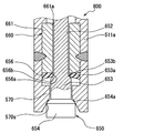
第5〜第7実施形態では、弾性部656が弁体650に設けられ、弾性部656にシート部653bが形成されていたが、図14に示す第8実施形態における燃料噴射弁800では、弾性部656が通路形成部材660の通路本体部661に取り付けられている。
(Eighth embodiment)
In the fifth to seventh embodiments, the elastic portion 656 is provided in the valve body 650 and the seat portion 653b is formed in the elastic portion 656. However, in the fuel injection valve 800 in the eighth embodiment shown in FIG. The portion 656 is attached to the passage main body 661 of the passage forming member 660.

以下、第5実施形態と構成が異なる通路形成部材660及び弁体650について詳細に説明する。通路形成部材660は、マルテンサイト系ステンレス鋼によって円筒状に形成されている通路本体部661及びフッ素系ゴム等の弾性部材によって円盤状に形成されている弾性部656から構成されている。   Hereinafter, the passage forming member 660 and the valve body 650 having different configurations from the fifth embodiment will be described in detail. The passage forming member 660 includes a passage main body portion 661 formed in a cylindrical shape by martensitic stainless steel and an elastic portion 656 formed in a disk shape by an elastic member such as fluorine rubber.

通路本体部661は、径方向中央部を軸方向に貫通する燃料通路661aを形成している。通路本体部661は、レーザ溶接等により第1磁性部511の小径部511aに結合され、固定されている。   The passage main body 661 forms a fuel passage 661a that penetrates the radial center in the axial direction. The passage main body 661 is coupled and fixed to the small diameter portion 511a of the first magnetic portion 511 by laser welding or the like.

弾性部656は、通路本体部661において弁体650側の端面に取り付けられている。弾性部656において径方向中央部には、軸方向に貫通する貫通孔656aが形成されている。貫通孔656aと燃料通路661aとは同軸上に配置されている。弾性部656において弁体650側の表面には、貫通孔656aを囲むような弁座部656bが形成されている。   The elastic portion 656 is attached to the end surface of the passage body 661 on the valve body 650 side. In the elastic portion 656, a through hole 656a penetrating in the axial direction is formed at a central portion in the radial direction. The through hole 656a and the fuel passage 661a are arranged coaxially. A valve seat portion 656b surrounding the through hole 656a is formed on the surface of the elastic portion 656 on the valve body 650 side.

弁体650は、非磁性体として機能するマルテンサイト系ステンレス鋼によって棒状に形成されており、第1磁性部511の内周側に同軸上に収容されている。弁体650は、連結部652、小径部653、及び大径部654を有する。   The valve body 650 is formed in a rod shape from martensitic stainless steel functioning as a nonmagnetic material, and is accommodated coaxially on the inner peripheral side of the first magnetic portion 511. The valve body 650 includes a connecting portion 652, a small diameter portion 653, and a large diameter portion 654.

連結部652は、第5実施形態の連結部652と同様の形状及び機能を有するものであり、可動コア540に連結される。連結部652は、第5実施形態と同様の燃料通路を形成している。   The connecting part 652 has the same shape and function as the connecting part 652 of the fifth embodiment, and is connected to the movable core 540. The connecting portion 652 forms a fuel passage similar to that in the fifth embodiment.

小径部653は、第5実施形態の小径部553と同様のもので、連結部652よりも噴孔570b側に配置されている。小径部653の連結部652側の段差部653aには、弁座部656bに離着座可能なシート部653bが形成されている。   The small diameter portion 653 is the same as the small diameter portion 553 of the fifth embodiment, and is disposed closer to the injection hole 570b than the connection portion 652. A seat portion 653b that can be attached to and detached from the valve seat portion 656b is formed on the step portion 653a on the connecting portion 652 side of the small diameter portion 653.

大径部654は、第5実施形態の大径部554と同様のもので、小径部653よりも噴孔570b側に配置されている。大径部654は、噴孔570bに向かうに従い徐々に拡径する当接面654aを有する。当接面654aは、テーパ面570aと当接することにより、弁体650の入口部材520側への移動、即ち、弁体650の閉塞方向への移動を規制する。また、大径部654の外径は、当接面654aがテーパ面570aから離れる方向に弁体650が移動したときに、当接面654aとテーパ面570aとの間を通過した燃料が噴孔570bに導かれるように設定されている。   The large diameter portion 654 is the same as the large diameter portion 554 of the fifth embodiment, and is disposed closer to the injection hole 570b than the small diameter portion 653. The large diameter portion 654 has a contact surface 654a that gradually increases in diameter toward the nozzle hole 570b. The contact surface 654a abuts the tapered surface 570a, thereby restricting the movement of the valve body 650 toward the inlet member 520, that is, the movement of the valve body 650 in the closing direction. Further, the outer diameter of the large-diameter portion 654 is such that the fuel that has passed between the contact surface 654a and the tapered surface 570a when the valve body 650 moves in a direction in which the contact surface 654a moves away from the tapered surface 570a is an injection hole. It is set to be guided to 570b.

以上のように構成された通路形成部材660及び弁体650によっても、弁体650の当接面654aがストッパ570のテーパ面570aに当接することにより、弁体650の入口部材520側への移動が規制されるので、通路形成部材660に設けられた弾性部656の潰れ代を所定の値にすることができる。   Also with the passage forming member 660 and the valve body 650 configured as described above, the contact surface 654a of the valve body 650 contacts the tapered surface 570a of the stopper 570, whereby the valve body 650 moves toward the inlet member 520. Therefore, the crushing margin of the elastic portion 656 provided in the passage forming member 660 can be set to a predetermined value.

次に、弾性部656の潰れ代の調整について説明する。距離計測工程において、第1磁性部511の開口部511cを基準位置とし、その基準位置から通路形成部材660の弁座部656bまでの距離を計測する。次に、挿入量算出工程において、距離計測工程での計測結果、予め計測されているストッパ570の各部寸法、特に、ストッパ570の軸方向端面からテーパ面570aにおいて、弁体650の当接面654aと当接する位置までの距離、及び予め定められた弾性部656の潰れ代(所定の値)に基づいて、ストッパ570の挿入量を算出する。その後、ストッパ570を開口部511cに算出した挿入量分だけ挿入し、ストッパ570をレーザ溶接等により第1磁性部511に結合し、固定する。なお、この実施形態においても、第5実施形態と同様に、レーザ溶接等による第1磁性部511及びストッパ570の熱ひずみの発生を加味して挿入量を算出すると良い。   Next, adjustment of the crushing allowance of the elastic part 656 will be described. In the distance measuring step, the opening 511c of the first magnetic part 511 is used as a reference position, and the distance from the reference position to the valve seat part 656b of the passage forming member 660 is measured. Next, in the insertion amount calculation step, the measurement result in the distance measurement step, the dimensions of each part of the stopper 570 that are measured in advance, in particular, the contact surface 654a of the valve body 650 from the axial end surface of the stopper 570 to the tapered surface 570a. The amount of insertion of the stopper 570 is calculated based on the distance to the position where the stopper 570 comes into contact with and a predetermined crushing allowance (predetermined value) of the elastic portion 656. Thereafter, the stopper 570 is inserted into the opening 511c by the calculated insertion amount, and the stopper 570 is coupled and fixed to the first magnetic part 511 by laser welding or the like. Also in this embodiment, similarly to the fifth embodiment, it is preferable to calculate the insertion amount in consideration of the occurrence of thermal strain of the first magnetic part 511 and the stopper 570 due to laser welding or the like.

なお、本実施形態のストッパ570は、ハウジング510と一体となっているが、第5実施形態のストッパ570とハウジング510とを別部材としても良い。さらに、本実施形態において通路形成部材660の結合方法として、第7実施形態のように、通路形成部材660をスポット溶接によりハウジング510に結合させ、固定させても良い。この場合、通路本体部661の径方向外周面にOリング561を設けると良い。これにより、通路本体部661とハウジング510とのシール性を確保することができる。   Although the stopper 570 of this embodiment is integrated with the housing 510, the stopper 570 and the housing 510 of the fifth embodiment may be separate members. Further, in this embodiment, as a method of coupling the passage forming member 660, the passage forming member 660 may be coupled to the housing 510 by spot welding and fixed as in the seventh embodiment. In this case, an O-ring 561 is preferably provided on the radially outer peripheral surface of the passage main body 661. Thereby, the sealing performance between the passage main body 661 and the housing 510 can be ensured.

なお、本実施形態において、ハウジング510が請求項に記載の「本体」に相当し、燃料通路661aが請求項に記載の「噴孔に通じる燃料通路」に相当し、通路本体部661が請求項に記載の「通路形成部」に相当し、弁体650が請求項に記載の「弁部材」に相当し、弾性部656が請求項に記載の「弾性部材」に相当し、ストッパ570が請求項に記載の「移動規制部」に相当する。   In the present embodiment, the housing 510 corresponds to the “main body” recited in the claims, the fuel passage 661a corresponds to the “fuel passage communicating with the nozzle hole” recited in the claims, and the passage main body 661 is claimed. The valve body 650 corresponds to the “valve member” described in the claims, the elastic portion 656 corresponds to the “elastic member” described in the claims, and the stopper 570 is charged. This corresponds to the “movement restriction unit” described in the section.

(第9実施形態)
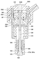
本発明の第9実施形態について説明する。図15(a)は第9実施形態に係る燃料噴射弁を示す断面図、図15(b)は図15(a)の燃料噴射弁の要部を示す拡大断面図である。
(Ninth embodiment)
A ninth embodiment of the present invention will be described. FIG. 15A is a cross-sectional view showing a fuel injection valve according to the ninth embodiment, and FIG. 15B is an enlarged cross-sectional view showing a main part of the fuel injection valve of FIG.

図15に示すように、燃料噴射弁は、金属よりなる複数の構成部材を接合して形成された筒状のボデー1xを備え、通電時に磁界を形成する円筒状のコイル2xがボデー1xの外周側に配置され、電磁力によって駆動されて往復動する金属製の弁体3xがボデー1x内に配置されている。   As shown in FIG. 15, the fuel injection valve includes a cylindrical body 1x formed by joining a plurality of constituent members made of metal, and a cylindrical coil 2x that forms a magnetic field when energized has an outer periphery of the body 1x. A metal valve element 3x that is disposed on the side and reciprocates by being driven by electromagnetic force is disposed in the body 1x.

そして、図示しない燃料供給装置から供給される水素やCNG(圧縮天然ガス)等の気体燃料は、ボデー1xにおける図15(a)の紙面上端部からボデー1x内に流入し、ボデー1x内を流れて、ボデー1xにおける図15(a)の紙面下端部から図示しない内燃機関の燃焼室に直接噴射されるようになっている。   Then, gaseous fuel such as hydrogen or CNG (compressed natural gas) supplied from a fuel supply device (not shown) flows into the body 1x from the upper end of the paper 1x in FIG. 15A and flows through the body 1x. Thus, the body 1x is directly injected into the combustion chamber of an internal combustion engine (not shown) from the lower end of the paper surface of FIG.

なお、ボデー1x、コイル2x、および弁体3xは、同軸状に配置されており、以下、それらの共通軸線を単に軸線といい、それらの共通軸線の方向を単に軸方向といい、それらの共通軸線に対して直交する方向を単に径方向という。   The body 1x, the coil 2x, and the valve body 3x are coaxially arranged. Hereinafter, the common axis is simply referred to as an axis, and the direction of the common axis is simply referred to as the axial direction. The direction orthogonal to the axis is simply called the radial direction.

ボデー1xは、燃料流れ上流側から燃料流れ下流側に沿って順に、円筒ないしは略円筒状の第1〜第5筒部10x〜14xが配置されている。また、第5筒部14x内に、円筒状の第6筒部15xが配置されている。   In the body 1x, first to fifth cylindrical portions 10x to 14x having a cylindrical shape or a substantially cylindrical shape are arranged in order from the fuel flow upstream side to the fuel flow downstream side. Moreover, the cylindrical 6th cylinder part 15x is arrange | positioned in the 5th cylinder part 14x.

第1筒部10xには、燃料供給装置から供給される燃料の入口となる燃料入口穴100xが形成されている。第2筒部11xは、磁性体金属よりなり、磁気回路を構成する。第3筒部12xは、非磁性体金属よりなる。第4筒部13xは、磁性体金属よりなり、径方向内側に向かって突出するリフト規制部130xを備え、磁気回路を構成する。   A fuel inlet hole 100x serving as an inlet for fuel supplied from the fuel supply device is formed in the first cylinder portion 10x. The 2nd cylinder part 11x consists of a magnetic body metal, and comprises a magnetic circuit. The third cylinder portion 12x is made of a nonmagnetic metal. The fourth cylinder portion 13x is made of a magnetic metal and includes a lift restricting portion 130x that protrudes inward in the radial direction, and constitutes a magnetic circuit.

第2ボデーとしての第5筒部14xは、耐食性に富む金属(例えばステンレス)よりなり、第5筒部14xにおける燃料流れ下流側の端部には、弁体3xの下流側可動シート部(詳細後述)と接離して燃料通路を開閉する下流側ボデーシート部140xが形成されている。この下流側ボデーシート部140xは、燃料流れ上流側から燃料流れ下流側に向かって拡がるテーパになっている。   The fifth cylindrical portion 14x as the second body is made of a metal (for example, stainless steel) rich in corrosion resistance, and the downstream movable seat portion (details) of the valve body 3x is provided at the end of the fifth cylindrical portion 14x on the downstream side of the fuel flow. A downstream body seat portion 140x that opens and closes the fuel passage is formed in contact with and away from (described later). The downstream body seat portion 140x has a taper that expands from the fuel flow upstream side toward the fuel flow downstream side.

第1ボデーとしての第6筒部15xは、耐食性に富む金属(例えばステンレス)よりなり、下流側ボデーシート部140xよりも燃料流れ上流側に配置されている。第6筒部15xにおける燃料流れ下流側の端部には、弁体3xの上流側可動シート部(詳細後述)と接離して燃料通路を開閉する上流側ボデーシート部150xが形成されている。この上流側ボデーシート部150xは、燃料流れ上流側から燃料流れ下流側に向かって拡がるテーパになっている。   The sixth cylinder portion 15x as the first body is made of a metal (for example, stainless steel) having a high corrosion resistance, and is disposed on the upstream side of the fuel flow with respect to the downstream body seat portion 140x. An upstream body seat portion 150x that opens and closes the fuel passage by contacting and separating from an upstream movable seat portion (details will be described later) of the valve body 3x is formed at the end of the sixth cylinder portion 15x on the downstream side of the fuel flow. The upstream body seat portion 150x has a taper that expands from the fuel flow upstream side toward the fuel flow downstream side.

弁体3xは、燃料流れ上流側から燃料流れ下流側に沿って順に、円柱状の第1〜第3軸部30x、31x、32xが形成されている。第1〜第3軸部30x、31x、32xのうち、第1軸部30xが最も小径であり、第3軸部32xが最も大径である。   The valve body 3x is formed with cylindrical first to third shaft portions 30x, 31x, and 32x in order from the fuel flow upstream side to the fuel flow downstream side. Of the first to third shaft portions 30x, 31x, and 32x, the first shaft portion 30x has the smallest diameter, and the third shaft portion 32x has the largest diameter.

第1軸部30xには、燃料流れ上流側の端面から軸方向に延びる燃料通路としての弁体縦穴300x、および径方向に延びてボデー1x内の空間と弁体縦穴300xとを連通する燃料通路としての弁体横穴301xが形成されている。   The first shaft portion 30x has a valve body vertical hole 300x as a fuel passage extending in the axial direction from the end face on the upstream side of the fuel flow, and a fuel passage extending in the radial direction to communicate the space in the body 1x with the valve body vertical hole 300x. As a valve body side hole 301x is formed.

第2軸部31xにおける燃料流れ上流側の端部には、金属よりも弾性に富み且つ耐熱性に富む弾性材よりなる環状の上流側可動シート部310xが接合されている。そして、上流側可動シート部310xは、ボデー1xの上流側ボデーシート部150xと接離して燃料通路を開閉するようになっている。   An annular upstream movable seat portion 310x made of an elastic material richer in elasticity and heat resistant than metal is joined to the end of the second shaft portion 31x on the upstream side of the fuel flow. The upstream movable seat portion 310x opens and closes the fuel passage by contacting and separating from the upstream body seat portion 150x of the body 1x.

なお、上流側可動シート部310xは、具体的には、フッ素ゴム、アクリロニトリルブタジエンゴム(NBR)、フッ素樹脂、四フッ化エチレン(PTFE)、ポリブチレンテレフタレート(PBT)等を用いることができる。   Specifically, the upstream movable sheet portion 310x may be made of fluoro rubber, acrylonitrile butadiene rubber (NBR), fluororesin, tetrafluoroethylene (PTFE), polybutylene terephthalate (PBT), or the like.

ここで、上流側ボデーシート部150xと上流側可動シート部310xとで構成される上流側の弁部は、一方のシート部が弾性材にて構成されているため、以下、上流側の弁部を弾性シール弁部という。   Here, since the upstream valve portion composed of the upstream body seat portion 150x and the upstream movable seat portion 310x has one seat portion made of an elastic material, hereinafter, the upstream valve portion Is called an elastic seal valve.

第3軸部32xにおける燃料流れ上流側の端部には、ボデー1xの下流側ボデーシート部140xと接離して燃料通路を開閉する下流側可動シート部320xが形成されている。この下流側可動シート部320xは、上流側可動シート部310xよりも燃料流れ下流側に位置している。   At the end of the third shaft portion 32x on the upstream side of the fuel flow, there is formed a downstream movable seat portion 320x that opens and closes the fuel passage by contacting and separating from the downstream body seat portion 140x of the body 1x. The downstream movable seat portion 320x is located downstream of the fuel flow with respect to the upstream movable seat portion 310x.

なお、下流側ボデーシート部140xと下流側可動シート部320xとで構成される下流側の弁部は、両シート部がともに金属で構成されているため、以下、下流側の弁部をメタルシール弁部という。   In addition, since the downstream valve portion composed of the downstream body seat portion 140x and the downstream movable seat portion 320x is made of metal, the downstream valve portion is hereinafter referred to as a metal seal. It is called a valve.

ここで、メタルシール弁部の開弁時の流路面積を、弾性シール弁部の開弁時の流路面積よりも小さくし、且つ、弾性シール弁部のシート径D2xをメタルシール弁部のシート径D1xよりも小さくするために、上流側ボデーシート部150xのテーパ角を、下流側ボデーシート部140xのテーパ角よりも大きくしている。   Here, the flow passage area when the metal seal valve portion is opened is made smaller than the flow passage area when the elastic seal valve portion is opened, and the seat diameter D2x of the elastic seal valve portion is made smaller than that of the metal seal valve portion. In order to make it smaller than the seat diameter D1x, the taper angle of the upstream body seat portion 150x is made larger than the taper angle of the downstream body seat portion 140x.

上流側可動シート部310xと下流側可動シート部320xは、弁体3xの往復動方向(すなわち軸方向)に沿って配置されている。そして、上流側可動シート部310xから下流側可動シート部320xに向かう向き(すなわち図15の紙面下方向き)に弁体3xが移動することにより、燃料通路が開かれるようになっており、換言すると、本実施形態の燃料噴射弁は所謂外開弁として構成されている。   The upstream movable seat portion 310x and the downstream movable seat portion 320x are disposed along the reciprocating direction (that is, the axial direction) of the valve body 3x. The fuel passage is opened when the valve element 3x moves in the direction from the upstream movable sheet portion 310x toward the downstream movable sheet portion 320x (that is, downward in the drawing in FIG. 15). The fuel injection valve of this embodiment is configured as a so-called externally opened valve.

第1軸部30xにおける燃料流れ上流側の端部には、磁性体金属よりなるアーマチャ4xが接合されている。より詳細には、アーマチャ4xは、ボデー1xの第1〜第4筒部10x〜13にて囲まれた空間、すなわち第4筒部13xのリフト規制部130xよりも燃料流れ上流側に位置している。なお、弁体3xおよびアーマチャ4xは、本発明の可動部を構成する。   An armature 4x made of a magnetic metal is joined to the end of the first shaft portion 30x on the upstream side of the fuel flow. More specifically, the armature 4x is located in the space surrounded by the first to fourth cylinder portions 10x to 13 of the body 1x, that is, on the fuel flow upstream side of the lift restricting portion 130x of the fourth cylinder portion 13x. Yes. The valve body 3x and the armature 4x constitute a movable part of the present invention.

ボデー1xの第4〜第6筒部13x〜15xにて囲まれた空間、すなわち第4筒部13xのリフト規制部130xよりも燃料流れ下流側には、弁体3xを閉弁向きに付勢するスプリング5xが配置されている。換言すると、弾性シール弁部およびメタルシール弁部は、スプリング5xよりも燃料流れ下流側に配置されている。なお、スプリング5xは、コイルスプリングであり、弁体3xはこのスプリング5x内を貫通して配置されている。   The valve body 3x is urged toward the valve closing direction in the space surrounded by the fourth to sixth cylinder portions 13x to 15x of the body 1x, that is, on the downstream side of the fuel flow from the lift restricting portion 130x of the fourth cylinder portion 13x. A spring 5x is disposed. In other words, the elastic seal valve portion and the metal seal valve portion are arranged on the fuel flow downstream side of the spring 5x. The spring 5x is a coil spring, and the valve body 3x is disposed so as to penetrate through the spring 5x.

第1軸部30xにおける軸方向中間部の外周側には、スプリング5xを受けるばね受け6x、およびスプリング5xのセット荷重を調整するためのCリング構造のシム7xが配置されている。   A spring receiver 6x that receives the spring 5x and a shim 7x having a C-ring structure for adjusting the set load of the spring 5x are disposed on the outer peripheral side of the axially intermediate portion of the first shaft portion 30x.

次に、上記構成になる燃料噴射弁の作動について説明する。まず、コイル2xに通電すると、電磁力によりアーマチャ4xがリフト規制部130x側に吸引される。そして、アーマチャ4xとともに弁体3xが移動して、上流側可動シート部310xと上流側ボデーシート部150xが離れて弾性シール弁部が開弁状態になると共に、下流側可動シート部320xと下流側ボデーシート部140xが離れてメタルシール弁部も開弁状態になり、気体燃料が燃焼室に噴射される。   Next, the operation of the fuel injection valve configured as described above will be described. First, when the coil 2x is energized, the armature 4x is attracted to the lift restricting portion 130x side by electromagnetic force. Then, the valve body 3x moves together with the armature 4x, the upstream movable seat portion 310x and the upstream body seat portion 150x are separated to open the elastic seal valve portion, and the downstream movable seat portion 320x and the downstream side The body seat part 140x is separated, the metal seal valve part is also opened, and gaseous fuel is injected into the combustion chamber.

ここで、開弁に必要な吸引力は、弾性シール弁部の受圧面積×燃圧と相関がある。そして、弾性シール弁部のシート径D2xをメタルシール弁部のシート径D1xよりも小さくしているため、弾性シール弁部の受圧面積はメタルシール弁部の受圧面積よりも小さくなり、したがって、開弁に必要な吸引力を小さくすることができる。   Here, the suction force required for valve opening correlates with the pressure receiving area of the elastic seal valve portion × the fuel pressure. Since the seat diameter D2x of the elastic seal valve portion is smaller than the seat diameter D1x of the metal seal valve portion, the pressure receiving area of the elastic seal valve portion is smaller than the pressure receiving area of the metal seal valve portion. The suction force required for the valve can be reduced.

コイル2xへの通電が停止されると、弁体3xはスプリング5xにより第1筒部10x側に向かって(すなわち閉弁向きに)付勢される。これにより、まず上流側可動シート部310xと上流側ボデーシート部150xが当接して弾性シール弁部が閉弁状態になり、気体燃料の噴射が停止される。そして、上流側可動シート部310xは弾性材よりなるため、閉弁時の良好なシール性が確保される。また、上流側可動シート部310xが軸方向に圧縮されて、下流側可動シート部320xと下流側ボデーシート部140xが当接し、メタルシール弁部も閉弁状態になる。   When the energization of the coil 2x is stopped, the valve body 3x is biased toward the first tube portion 10x by the spring 5x (that is, in the valve closing direction). As a result, the upstream movable seat portion 310x and the upstream body seat portion 150x first come into contact with each other, the elastic seal valve portion is closed, and the injection of gaseous fuel is stopped. And since the upstream movable sheet part 310x consists of an elastic material, the favorable sealing performance at the time of valve closing is ensured. Further, the upstream movable seat portion 310x is compressed in the axial direction, the downstream movable seat portion 320x and the downstream body seat portion 140x come into contact with each other, and the metal seal valve portion is also closed.

ここで、気体燃料を燃焼室に直接噴射する形式の内燃機関では、通常、噴射終了後に点火プラグにより点火して燃料を燃焼させるので、燃焼ガスが燃料噴射弁の内部へ流入しようとする時には、メタルシール弁部が閉弁状態となっている。したがって、メタルシール弁部の閉弁により、高温の燃焼ガスが弾性シール弁部に流れることが防止され、上流側可動シート部310xの溶損が防止される。   Here, in the internal combustion engine of the type in which the gaseous fuel is directly injected into the combustion chamber, normally, the fuel is combusted by igniting with the spark plug after the completion of the injection, so when the combustion gas is going to flow into the fuel injection valve, The metal seal valve is closed. Therefore, by closing the metal seal valve portion, high-temperature combustion gas is prevented from flowing to the elastic seal valve portion, and melting of the upstream movable seat portion 310x is prevented.

因みに、燃料噴射中に点火されて燃焼する形式の内燃機関の場合、燃焼ガス圧よりも気体燃料の供給圧力のほうが高く設定されるので、燃焼ガスは上流側可動シート部310xに到達できない。また、メタルシール弁部は、閉弁中であっても多少の漏れが許容される。なぜなら、燃焼ガスは漏れようとする際に膨張して温度が下がり、高温であった燃焼ガスも上流側可動シート部310xに達する時は非常に温度が低い状態になっているので、上流側可動シート部310xを溶損させることはない。   Incidentally, in the case of an internal combustion engine of a type that is ignited and burned during fuel injection, the supply pressure of the gaseous fuel is set higher than the combustion gas pressure, so that the combustion gas cannot reach the upstream movable seat portion 310x. Further, the metal seal valve portion is allowed to leak somewhat even when the valve is closed. This is because the combustion gas expands when it tries to leak and the temperature decreases, and when the combustion gas that has been hot reaches the upstream movable seat portion 310x, the temperature is very low, so the upstream movable The sheet part 310x is not melted.

なお、弾性シール弁部とメタルシール弁部の軸方向距離を長くするほど、上流側可動シート部310xに対する燃焼ガスの熱の影響を少なくすることができる。また、弾性シール弁部とメタルシール弁部との間に残留した燃料が閉弁中に燃焼室に漏れることは、内燃機関の燃焼を制御する上で望ましくない。したがって、その両者を考慮して、弾性シール弁部とメタルシール弁部の軸方向距離を設定することが望ましい。   As the axial distance between the elastic seal valve portion and the metal seal valve portion is increased, the influence of the heat of the combustion gas on the upstream movable seat portion 310x can be reduced. In addition, it is not desirable for the fuel remaining between the elastic seal valve portion and the metal seal valve portion to leak into the combustion chamber while the valve is closed in order to control the combustion of the internal combustion engine. Therefore, it is desirable to set the axial distance between the elastic seal valve portion and the metal seal valve portion in consideration of both.

次に、上記構成になる燃料噴射弁の製造方法について説明する。   Next, a method for manufacturing the fuel injection valve having the above configuration will be described.

ここで、下流側ボデーシート部140xと下流側可動シート部320xとで構成されるメタルシール弁部のセット荷重の目標値をメタルシール弁部セット荷重設定値F1xとし、上流側ボデーシート部150xと上流側可動シート部310xとで構成される弾性シール弁部のセット荷重の目標値を弾性シール弁部セット荷重設定値F2xとし、メタルシール弁部セット荷重設定値F1xと弾性シール弁部セット荷重設定値F2xの和を全セット荷重設定値Fxとする。   Here, the target value of the set load of the metal seal valve portion composed of the downstream body seat portion 140x and the downstream movable seat portion 320x is set to the metal seal valve portion set load set value F1x, and the upstream body seat portion 150x The target value of the set load of the elastic seal valve portion constituted by the upstream movable seat portion 310x is set as the elastic seal valve portion set load setting value F2x, and the metal seal valve portion set load set value F1x and the elastic seal valve portion set load setting are set. The sum of the values F2x is set as the all set load setting value Fx.

まず、弁体3xと第5筒部14xを組み付け、図示しない第1治具にて弁体3xを付勢して下流側可動シート部320xを下流側ボデーシート部140xに押しつける。このとき、第1治具は、全セット荷重設定値Fx相当の荷重にて弁体3xを付勢する。   First, the valve body 3x and the fifth cylinder part 14x are assembled, and the valve body 3x is urged by a first jig (not shown) to press the downstream movable sheet part 320x against the downstream body sheet part 140x. At this time, the first jig biases the valve body 3x with a load corresponding to the all set load set value Fx.

続いて、その状態のまま、第6筒部15xを第5筒部14x内に挿入し、図示しない第2治具にて第6筒部15xを付勢して上流側ボデーシート部150xを上流側可動シート部310xに押しつける。このとき、第2治具は、弾性シール弁部セット荷重設定値F2x相当の荷重にて第6筒部15xを付勢する。   Subsequently, in this state, the sixth cylinder portion 15x is inserted into the fifth cylinder portion 14x, and the sixth cylinder portion 15x is urged by a second jig (not shown) to move the upstream body sheet portion 150x upstream. Press against the side movable sheet portion 310x. At this time, the second jig biases the sixth cylindrical portion 15x with a load corresponding to the elastic seal valve portion set load set value F2x.

因みに、この状態では、実際に下流側可動シート部320xが下流側ボデーシート部140xに押しつけられる力は、上流側ボデーシート部150xを上流側可動シート部310xに押しつける力の分だけ第1治具の付勢力よりも減少するため、メタルシール弁部セット荷重設定値F1x相当になる。   Incidentally, in this state, the force with which the downstream movable sheet part 320x is actually pressed against the downstream body sheet part 140x is equal to the first jig corresponding to the force pressing the upstream body sheet part 150x against the upstream movable sheet part 310x. Therefore, the metal seal valve portion set load set value F1x is equivalent.

したがって、このときの第5筒部14xと第6筒部15xの相対位置関係が、メタルシール弁部セット荷重および弾性シール弁部セット荷重を高精度に管理するうえで、第5筒部14xと第6筒部15xの最適位置関係となる。   Therefore, the relative positional relationship between the fifth cylinder part 14x and the sixth cylinder part 15x at this time is such that the metal seal valve part set load and the elastic seal valve part set load are managed with high accuracy. The optimum positional relationship of the sixth cylinder portion 15x is obtained.

続いて、その状態のまま、第5筒部14xと第6筒部15xを溶接にて一体化する。この際、全周溶接することにより、第5筒部14xと第6筒部15xとの間の気密を確保する。   Then, the 5th cylinder part 14x and the 6th cylinder part 15x are integrated by welding with the state. Under the present circumstances, the airtight between the 5th cylinder part 14x and the 6th cylinder part 15x is ensured by welding all around.

続いて、スプリング5xおよびばね受け6xを組み付け、さらに、スプリング5xのセット荷重が全セット荷重設定値Fx相当の荷重になるように、シム7xにてスプリング5xのセット長を調整する。これにより、メタルシール弁部にはメタルシール弁部セット荷重設定値F1x相当の荷重が作用し、弾性シール弁部には弾性シール弁部セット荷重設定値F2x相当の荷重が作用する。以上説明したように、本実施形態では、組み付け段階において第5筒部14xと第6筒部15xの相対位置を調整することにより、ボデー1xや弁体3xを高精度に加工しなくても、弾性シール弁部のセット荷重、およびメタルシール弁部のセット荷重を、容易に高精度に管理することができる。   Subsequently, the spring 5x and the spring receiver 6x are assembled, and the set length of the spring 5x is adjusted by the shim 7x so that the set load of the spring 5x becomes a load corresponding to the total set load setting value Fx. As a result, a load corresponding to the metal seal valve portion set load set value F1x acts on the metal seal valve portion, and a load equivalent to the elastic seal valve portion set load set value F2x acts on the elastic seal valve portion. As described above, in the present embodiment, by adjusting the relative positions of the fifth cylinder portion 14x and the sixth cylinder portion 15x at the assembly stage, the body 1x and the valve body 3x can be processed with high accuracy. The set load of the elastic seal valve part and the set load of the metal seal valve part can be easily managed with high accuracy.

また、弾性シール弁部のシート径D2xをメタルシール弁部のシート径D1xよりも小さくしているため、開弁に必要な吸引力を小さくすることができる。   Further, since the seat diameter D2x of the elastic seal valve portion is smaller than the seat diameter D1x of the metal seal valve portion, the suction force required for opening the valve can be reduced.

なお、上記実施形態においては、第5筒部14xと第6筒部15xを全周溶接したが、図16に示す第9実施形態の第1変形例のように、第5筒部14xと第6筒部15xを断続溶接にて一体化し、第5筒部14xと第6筒部15xとの間をシール部材8xにてシールしてもよい。これによると、全周溶接する場合よりも溶接コストを低減することができる。   In the above embodiment, the fifth cylinder portion 14x and the sixth cylinder portion 15x are welded all around. However, as in the first modification of the ninth embodiment shown in FIG. The six cylinder parts 15x may be integrated by intermittent welding, and the space between the fifth cylinder part 14x and the sixth cylinder part 15x may be sealed with the seal member 8x. According to this, welding cost can be reduced compared with the case where all-around welding is performed.

また、上記実施形態においては、上流側可動シート部310xを弾性材にて構成し、上流側ボデーシート部150xを金属にて構成したが、図17に示す第9実施形態の第2変形例のように、第6筒部15xにおける燃料流れ下流側の端部に、金属よりも弾性に富み且つ耐熱性に富む弾性材よりなる円板状の上流側ボデーシート部151xを接合し、第2軸部31xにおける燃料流れ上流側の端部に、上流側ボデーシート部151xと接離して燃料通路を開閉する上流側可動シート部311xを形成してもよい。すなわち、上流側ボデーシート部151xを弾性材にて構成し、上流側可動シート部311xを金属にて構成してもよい。   Moreover, in the said embodiment, although the upstream movable sheet part 310x was comprised with the elastic material and the upstream body sheet part 150x was comprised with the metal, it is a 2nd modification of 9th Embodiment shown in FIG. Thus, the disc-shaped upstream body seat portion 151x made of an elastic material richer in elasticity and heat resistance than the metal is joined to the end of the sixth cylinder portion 15x on the downstream side of the fuel flow, and the second shaft An upstream movable seat portion 311x that opens and closes the fuel passage may be formed in contact with and away from the upstream body seat portion 151x at the end of the portion 31x on the upstream side of the fuel flow. That is, the upstream body sheet portion 151x may be made of an elastic material, and the upstream movable sheet portion 311x may be made of a metal.

なお、上流側ボデーシート部151xは、燃料流れ上流側から燃料流れ下流側に向かって拡がるテーパになっている。また、上流側ボデーシート部151xのテーパ角は、下流側ボデーシート部140xのテーパ角よりも大きくなっている。   The upstream body seat portion 151x has a taper that extends from the upstream side of the fuel flow toward the downstream side of the fuel flow. Further, the taper angle of the upstream body seat portion 151x is larger than the taper angle of the downstream body seat portion 140x.

この第2変形例の場合、弁体3xよりもシンプルな形状の第6筒部15xに上流側ボデーシート部151xを接合するため、その接合が容易である。   In the case of this second modification, the upstream body seat portion 151x is joined to the sixth cylindrical portion 15x having a simpler shape than the valve body 3x, and hence the joining is easy.

(第10実施形態)
本発明の第10実施形態について説明する。図18は第10実施形態に係る燃料噴射弁を示す断面図である。
(10th Embodiment)
A tenth embodiment of the present invention will be described. FIG. 18 is a sectional view showing a fuel injection valve according to the tenth embodiment.

第9実施形態の燃料噴射弁は所謂外開弁として構成されているのに対し、本実施形態の燃料噴射弁は所謂内開弁として構成されている。以下、第9実施形態と異なる部分についてのみ説明する。   The fuel injection valve of the ninth embodiment is configured as a so-called outer valve, whereas the fuel injection valve of the present embodiment is configured as a so-called inner valve. Only the parts different from the ninth embodiment will be described below.

図18に示すように、ボデー1xは、第2筒部11x内に、円筒状の第4筒部13xが配置され、第5筒部14Ax内に、有底円筒状の第6筒部15Axが配置されている。第4筒部13xは、磁性体金属よりなり、アーマチャ4xに対向して配置されてリフト規制部として機能するものである。   As shown in FIG. 18, in the body 1x, a cylindrical fourth cylindrical portion 13x is disposed in the second cylindrical portion 11x, and a bottomed cylindrical sixth cylindrical portion 15Ax is disposed in the fifth cylindrical portion 14Ax. Has been placed. The fourth cylinder portion 13x is made of a magnetic metal and is disposed so as to face the armature 4x and functions as a lift restricting portion.

第1ボデーとしての第5筒部14Axにおける軸方向中間部には、弁体3xの上流側可動シート部(詳細後述)と接離して燃料通路を開閉する上流側ボデーシート部141xが形成されている。この上流側ボデーシート部141xは、燃料流れ下流側から燃料流れ上流側に向かって拡がるテーパになっている。   An upstream body seat portion 141x that opens and closes a fuel passage by being in contact with and away from an upstream movable seat portion (details will be described later) of the valve body 3x is formed in an axially intermediate portion of the fifth cylinder portion 14Ax as the first body. Yes. The upstream body seat portion 141x has a taper that expands from the fuel flow downstream side toward the fuel flow upstream side.

第2ボデーとしての第6筒部15Axは、上流側ボデーシート部141xよりも燃料流れ下流側に配置されている。第6筒部15Axにおける燃料流れ上流側の端部には、弁体3xの下流側可動シート部(詳細後述)と接離して燃料通路を開閉する下流側ボデーシート部152xが形成されている。この下流側ボデーシート部152xは、燃料流れ下流側から燃料流れ上流側に向かって拡がるテーパになっている。   The sixth cylinder portion 15Ax as the second body is arranged on the downstream side of the fuel flow with respect to the upstream body seat portion 141x. A downstream body seat portion 152x that opens and closes a fuel passage by contacting and separating from a downstream movable seat portion (details will be described later) of the valve body 3x is formed at the end of the sixth cylinder portion 15Ax on the upstream side of the fuel flow. The downstream body seat portion 152x has a taper that extends from the fuel flow downstream side toward the fuel flow upstream side.

第6筒部15Axにおける燃料流れ下流側の端部には、噴孔153xが形成されている。噴孔153xは液体燃料の微粒化に有効であり、したがって、本実施形態の燃料噴射弁は液体燃料を用いる場合に好適である。   An injection hole 153x is formed at the end of the sixth cylinder portion 15Ax on the downstream side of the fuel flow. The nozzle hole 153x is effective for atomization of liquid fuel, and therefore the fuel injection valve of the present embodiment is suitable when liquid fuel is used.

弁体3xは、燃料流れ上流側から燃料流れ下流側に沿って順に、円柱状の第1〜第3軸部30x、31x、32xが形成されている。第1〜第3軸部30x、31x、32xのうち、第1軸部30xが最も小径であり、第2軸部31xが最も大径である。   The valve body 3x is formed with cylindrical first to third shaft portions 30x, 31x, and 32x in order from the fuel flow upstream side to the fuel flow downstream side. Of the first to third shaft portions 30x, 31x, and 32x, the first shaft portion 30x has the smallest diameter, and the second shaft portion 31x has the largest diameter.

第2軸部31xにおける燃料流れ下流側の端部には、金属よりも弾性に富み且つ耐熱性に富む弾性材よりなる環状の上流側可動シート部310xが接合されている。そして、上流側可動シート部310xは、ボデー1xの上流側ボデーシート部141xと接離して燃料通路を開閉するようになっている。   An annular upstream movable seat portion 310x made of an elastic material richer in elasticity and heat-resistant than metal is joined to the end of the second shaft portion 31x on the downstream side of the fuel flow. The upstream movable seat portion 310x opens and closes the fuel passage by contacting and separating from the upstream body seat portion 141x of the body 1x.

なお、上流側可動シート部310xは、具体的には、フッ素ゴム、アクリロニトリルブタジエンゴム(NBR)、フッ素樹脂、四フッ化エチレン(PTFE)、ポリブチレンテレフタレート(PBT)等を用いることができる。   Specifically, the upstream movable sheet portion 310x may be made of fluoro rubber, acrylonitrile butadiene rubber (NBR), fluororesin, tetrafluoroethylene (PTFE), polybutylene terephthalate (PBT), or the like.

ここで、上流側ボデーシート部141xと上流側可動シート部310xとで構成される上流側の弁部は、一方のシート部が弾性材にて構成されているため、以下、上流側の弁部を弾性シール弁部という。   Here, since the upstream valve portion composed of the upstream body seat portion 141x and the upstream movable seat portion 310x has one seat portion made of an elastic material, hereinafter, the upstream valve portion. Is called an elastic seal valve.

第3軸部32xにおける燃料流れ下流側の端部には、ボデー1xの下流側ボデーシート部152xと接離して燃料通路を開閉する下流側可動シート部320xが形成されている。この下流側可動シート部320xは、上流側可動シート部310xよりも燃料流れ下流側に位置している。   At the end of the third shaft portion 32x on the downstream side of the fuel flow, there is formed a downstream movable seat portion 320x that contacts and separates from the downstream body seat portion 152x of the body 1x to open and close the fuel passage. The downstream movable seat portion 320x is located downstream of the fuel flow with respect to the upstream movable seat portion 310x.

なお、下流側ボデーシート部152xと下流側可動シート部320xとで構成される下流側の弁部は、両シート部がともに金属で構成されているため、以下、下流側の弁部をメタルシール弁部という。   In addition, since the downstream valve portion composed of the downstream body seat portion 152x and the downstream movable seat portion 320x is made of metal, the downstream valve portion is hereinafter referred to as a metal seal. It is called a valve.

上流側可動シート部310xと下流側可動シート部320xは、弁体3xの往復動方向(すなわち軸方向)に沿って配置されている。そして、下流側可動シート部320xから上流側可動シート部310xに向かう向き(すなわち図18の紙面上方向き)に弁体3xが移動することにより、燃料通路が開かれるようになっており、換言すると、本実施形態の燃料噴射弁は所謂内開弁として構成されている。   The upstream movable seat portion 310x and the downstream movable seat portion 320x are disposed along the reciprocating direction (that is, the axial direction) of the valve body 3x. The fuel passage is opened when the valve element 3x moves in the direction from the downstream movable sheet portion 320x toward the upstream movable sheet portion 310x (that is, upward in the drawing in FIG. 18). The fuel injection valve of the present embodiment is configured as a so-called inner open valve.

第1軸部30xにおける燃料流れ上流側の端部には、磁性体金属よりなるアーマチャ4xが接合されている。より詳細には、アーマチャ4xは、ボデー1xの第2〜第5筒部11x〜14xにて囲まれた空間、すなわち第4筒部13xよりも燃料流れ下流側に位置している。   An armature 4x made of a magnetic metal is joined to the end of the first shaft portion 30x on the upstream side of the fuel flow. More specifically, the armature 4x is located in the space surrounded by the second to fifth cylinder parts 11x to 14x of the body 1x, that is, the fuel flow downstream side of the fourth cylinder part 13x.

第4筒部13x内に円筒状のばね受け6xが圧入されている。そして、ばね受け6xとアーマチャ4xとの間に、弁体3xを閉弁向きに付勢するスプリング5xが配置されている。   A cylindrical spring receiver 6x is press-fitted into the fourth cylinder portion 13x. Between the spring receiver 6x and the armature 4x, a spring 5x that urges the valve body 3x in the valve closing direction is disposed.

次に、上記構成になる燃料噴射弁の作動について説明する。まず、コイル2xに通電すると、電磁力によりアーマチャ4xが第4筒部13x側に吸引される。そして、アーマチャ4xとともに弁体3xが移動して、上流側可動シート部310xと上流側ボデーシート部141xが離れて弾性シール弁部が開弁状態になると共に、下流側可動シート部320xと下流側ボデーシート部152xが離れてメタルシール弁部も開弁状態になり、噴孔153xを介して燃料が燃焼室に噴射される。   Next, the operation of the fuel injection valve configured as described above will be described. First, when the coil 2x is energized, the armature 4x is attracted to the fourth cylindrical portion 13x side by electromagnetic force. Then, the valve body 3x moves together with the armature 4x, the upstream movable seat portion 310x and the upstream body seat portion 141x are separated to open the elastic seal valve portion, and the downstream movable seat portion 320x and the downstream side The body seat portion 152x is separated and the metal seal valve portion is also opened, and fuel is injected into the combustion chamber through the injection hole 153x.

コイル2xへの通電が停止されると、弁体3xはスプリング5xにより第6筒部15Ax側に向かって(すなわち閉弁向きに)付勢される。これにより、まず上流側可動シート部310xと上流側ボデーシート部141xが当接して弾性シール弁部が閉弁状態にり、燃料の噴射が停止される。そして、上流側可動シート部310xは弾性材よりなるため、閉弁時の良好なシール性が確保される。また、上流側可動シート部310xが軸方向に圧縮されて、下流側可動シート部320xと下流側ボデーシート部152xが当接し、メタルシール弁部も閉弁状態になる。   When energization of the coil 2x is stopped, the valve body 3x is biased toward the sixth cylinder portion 15Ax by the spring 5x (that is, in the valve closing direction). Thus, the upstream movable seat portion 310x and the upstream body seat portion 141x first come into contact with each other, the elastic seal valve portion is closed, and fuel injection is stopped. And since the upstream movable sheet part 310x consists of an elastic material, the favorable sealing performance at the time of valve closing is ensured. Further, the upstream movable seat portion 310x is compressed in the axial direction, the downstream movable seat portion 320x and the downstream body seat portion 152x come into contact with each other, and the metal seal valve portion is also closed.

次に、上記構成になる燃料噴射弁の製造方法について説明する。   Next, a method for manufacturing the fuel injection valve having the above configuration will be described.

ここで、下流側ボデーシート部152xと下流側可動シート部320xとで構成されるメタルシール弁部のセット荷重の目標値をメタルシール弁部セット荷重設定値F1xとし、上流側ボデーシート部141xと上流側可動シート部310xとで構成される弾性シール弁部のセット荷重の目標値を弾性シール弁部セット荷重設定値F2xとし、メタルシール弁部セット荷重設定値F1xと弾性シール弁部セット荷重設定値F2xの和を全セット荷重設定値Fxとする。   Here, the target value of the set load of the metal seal valve portion composed of the downstream body seat portion 152x and the downstream movable seat portion 320x is set as the metal seal valve portion set load set value F1x, and the upstream body seat portion 141x The target value of the set load of the elastic seal valve portion constituted by the upstream movable seat portion 310x is set as the elastic seal valve portion set load setting value F2x, and the metal seal valve portion set load set value F1x and the elastic seal valve portion set load setting are set. The sum of the values F2x is set as the all set load setting value Fx.

まず、第2筒部11xと第3筒部12xと第5筒部14Axとを接合して一体化し、それに弁体3xを組み付け、図示しない第1治具にて弁体3xを付勢して上流側可動シート部310xを上流側ボデーシート部141xに押しつける。このとき、第1治具は、全セット荷重設定値Fx相当の荷重にて弁体3xを付勢する。   First, the second cylinder portion 11x, the third cylinder portion 12x, and the fifth cylinder portion 14Ax are joined and integrated, the valve body 3x is assembled thereto, and the valve body 3x is biased by a first jig (not shown). The upstream movable sheet portion 310x is pressed against the upstream body sheet portion 141x. At this time, the first jig biases the valve body 3x with a load corresponding to the all set load set value Fx.

続いて、その状態のまま、第6筒部15Axを第5筒部14Ax内に挿入し、図示しない第2治具にて第6筒部15Axを付勢して下流側ボデーシート部152xを下流側可動シート部320xに押しつける。このとき、第2治具は、メタルシール弁部セット荷重設定値F1x相当の荷重にて第6筒部15Axを付勢する。   Subsequently, in this state, the sixth cylinder portion 15Ax is inserted into the fifth cylinder portion 14Ax, and the sixth cylinder portion 15Ax is urged by a second jig (not shown) to move the downstream body sheet portion 152x downstream. Press against the side movable sheet portion 320x. At this time, the second jig biases the sixth cylindrical portion 15Ax with a load corresponding to the metal seal valve portion set load set value F1x.

因みに、この状態では、実際に上流側可動シート部310xが上流側ボデーシート部141xに押しつけられる力は、下流側ボデーシート部152xを下流側可動シート部320xに押しつける力の分だけ第1治具の付勢力よりも減少するため、弾性シール弁部セット荷重設定値F2x相当になる。   Incidentally, in this state, the force with which the upstream movable sheet portion 310x is actually pressed against the upstream body seat portion 141x is equal to the force with which the downstream body sheet portion 152x is pressed against the downstream movable sheet portion 320x. Therefore, the elastic seal valve portion set load setting value F2x is equivalent.

したがって、このときの第5筒部14Axと第6筒部15Axの相対位置関係が、メタルシール弁部セット荷重および弾性シール弁部セット荷重を高精度に管理するうえで、第5筒部14Axと第6筒部15Axの最適位置関係となる。   Accordingly, the relative positional relationship between the fifth cylinder portion 14Ax and the sixth cylinder portion 15Ax at this time is such that the metal seal valve portion set load and the elastic seal valve portion set load are managed with high accuracy. The optimum positional relationship of the sixth cylinder portion 15Ax is obtained.

続いて、その状態のまま、第5筒部14Axと第6筒部15Axを溶接にて一体化する。この際、全周溶接することにより、第5筒部14Axと第6筒部15Axとの間の気密を確保する。   Subsequently, in this state, the fifth cylinder portion 14Ax and the sixth cylinder portion 15Ax are integrated by welding. Under the present circumstances, the airtightness between 5th cylinder part 14Ax and 6th cylinder part 15Ax is ensured by welding all around.

続いて、スプリング5xを組み付け、さらに、スプリング5xのセット荷重が全セット荷重設定値Fx相当の荷重になるように、ばね受け6xの圧入量を調整してスプリング5xのセット長を調整する。これにより、メタルシール弁部にはメタルシール弁部セット荷重設定値F1x相当の荷重が作用し、弾性シール弁部には弾性シール弁部セット荷重設定値F2x相当の荷重が作用する。   Subsequently, the spring 5x is assembled, and the set length of the spring 5x is adjusted by adjusting the press-fitting amount of the spring receiver 6x so that the set load of the spring 5x is equivalent to the total set load setting value Fx. As a result, a load corresponding to the metal seal valve portion set load set value F1x acts on the metal seal valve portion, and a load equivalent to the elastic seal valve portion set load set value F2x acts on the elastic seal valve portion.

なお、燃料圧力により弁体3xを閉弁向きに付勢する荷重をF3としたとき、スプリング5xのセット荷重がFx−F3xになるように、ばね受け6xの圧入量を調整してスプリング5xのセット長を調整してもよい。これにより、燃料圧力が弁体3xに印加されている状態のときに、メタルシール弁部にはメタルシール弁部セット荷重設定値F1x相当の荷重が作用し、弾性シール弁部には弾性シール弁部セット荷重設定値F2x相当の荷重が作用する。   When the load that biases the valve body 3x toward the valve closing direction by the fuel pressure is F3, the press-fitting amount of the spring receiver 6x is adjusted so that the set load of the spring 5x becomes Fx-F3x. The set length may be adjusted. Thus, when the fuel pressure is applied to the valve body 3x, a load corresponding to the metal seal valve portion set load set value F1x acts on the metal seal valve portion, and the elastic seal valve portion has an elastic seal valve. A load corresponding to the set load setting value F2x is applied.

以上説明したように、本実施形態では、組み付け段階において第5筒部14Axと第6筒部15Axの相対位置を調整することにより、ボデー1xや弁体3xを高精度に加工しなくても、弾性シール弁部のセット荷重、およびメタルシール弁部のセット荷重を、容易に高精度に管理することができる。   As described above, in the present embodiment, by adjusting the relative positions of the fifth cylinder portion 14Ax and the sixth cylinder portion 15Ax at the assembly stage, the body 1x and the valve body 3x can be processed with high accuracy. The set load of the elastic seal valve part and the set load of the metal seal valve part can be easily managed with high accuracy.

なお、上記実施形態においては、第5筒部14Axと第6筒部15Axを全周溶接したが、図19に示す第10実施形態の第1変形例のように、第5筒部14Axと第6筒部15Axを断続溶接にて一体化し、第5筒部14Axと第6筒部15Axとの間をシール部材8xにてシールしてもよい。これによると、全周溶接する場合よりも溶接コストを低減することができる。   In addition, in the said embodiment, although 5th cylinder part 14Ax and 6th cylinder part 15Ax were welded all around, like 5th cylinder part 14Ax and 1st modification of 10th Embodiment shown in FIG. Six cylinder part 15Ax may be integrated by intermittent welding, and between 5th cylinder part 14Ax and 6th cylinder part 15Ax may be sealed with the sealing member 8x. According to this, welding cost can be reduced compared with the case where all-around welding is performed.

(第11実施形態)
本発明の第11実施形態について説明する。図20は第11実施形態に係る燃料噴射弁を示す断面図である。
(Eleventh embodiment)
An eleventh embodiment of the present invention will be described. FIG. 20 is a sectional view showing a fuel injection valve according to the eleventh embodiment.

本実施形態は、弾性シール弁部の位置が第9実施形態と異なっている。なお、その他に関しては第9実施形態と同様であるため、異なる部分についてのみ説明する。   In the present embodiment, the position of the elastic seal valve portion is different from that of the ninth embodiment. In addition, since it is the same as that of 9th Embodiment regarding others, only a different part is demonstrated.

図20に示すように、第6筒部15xに形成された上流側ボデーシート部150x、および、第2軸部31xに接合された上流側可動シート部310xは、いずれもスプリング5x、ばね受け6x、およびシム7xよりも燃料流れ上流側に配置されている。すなわち、上流側ボデーシート部150xと上流側可動シート部310xとで構成される弾性シール弁部は、スプリング5x、ばね受け6x、およびシム7xよりも燃料流れ上流側に配置されている。   As shown in FIG. 20, the upstream body sheet portion 150x formed on the sixth cylinder portion 15x and the upstream movable sheet portion 310x joined to the second shaft portion 31x are both a spring 5x and a spring receiver 6x. And the fuel flow upstream of the shim 7x. That is, the elastic seal valve portion constituted by the upstream body seat portion 150x and the upstream movable seat portion 310x is disposed on the fuel flow upstream side from the spring 5x, the spring receiver 6x, and the shim 7x.

弁体縦穴300xは、第2軸部31xまで延びており、弁体横穴301xは、第2軸部31xにおいて上流側可動シート部310xよりも燃料流れ下流側に形成されている。   The valve body vertical hole 300x extends to the second shaft portion 31x, and the valve body lateral hole 301x is formed in the second shaft portion 31x on the downstream side of the fuel flow with respect to the upstream movable seat portion 310x.

次に、上記構成になる燃料噴射弁の製造方法について説明する。   Next, a method for manufacturing the fuel injection valve having the above configuration will be described.

まず、第5筒部14x、弁体3x、スプリング5x、ばね受け6x、およびシム7xを組み付け、スプリング5xにて弁体3xを付勢して下流側可動シート部320xを下流側ボデーシート部140xに押しつける。このとき、スプリング5xのセット荷重が全セット荷重設定値Fx相当の荷重になるように、シム7xにてスプリング5xのセット長を調整する。   First, the fifth cylinder portion 14x, the valve body 3x, the spring 5x, the spring receiver 6x, and the shim 7x are assembled, and the valve body 3x is urged by the spring 5x to move the downstream movable seat portion 320x to the downstream body seat portion 140x. Press against. At this time, the set length of the spring 5x is adjusted by the shim 7x so that the set load of the spring 5x becomes a load corresponding to the total set load set value Fx.

続いて、その状態のまま、第6筒部15xを第5筒部14x内に挿入し、図示しない治具にて第6筒部15xを付勢して上流側ボデーシート部150xを上流側可動シート部310xに押しつける。このとき、治具は、弾性シール弁部セット荷重設定値F2x相当の荷重にて第6筒部15xを付勢する。   Subsequently, in this state, the sixth cylinder portion 15x is inserted into the fifth cylinder portion 14x, the sixth cylinder portion 15x is urged by a jig (not shown), and the upstream body seat portion 150x is movable upstream. Press against the sheet portion 310x. At this time, the jig biases the sixth cylindrical portion 15x with a load corresponding to the elastic seal valve portion set load set value F2x.

因みに、この状態では、実際に下流側可動シート部320xが下流側ボデーシート部140xに押しつけられる力は、上流側ボデーシート部150xを上流側可動シート部310xに押しつける力の分だけスプリング5xのセット荷重よりも減少するため、メタルシール弁部セット荷重設定値F1x相当になる。   Incidentally, in this state, the force with which the downstream movable sheet part 320x is actually pressed against the downstream body sheet part 140x is set by the amount of the force pressing the upstream body sheet part 150x against the upstream movable sheet part 310x. Since it is smaller than the load, it corresponds to the metal seal valve portion set load set value F1x.

続いて、その状態のまま、第5筒部14xと第6筒部15xを溶接にて一体化する。この際、全周溶接することにより、第5筒部14xと第6筒部15xとの間の気密を確保する。   Then, the 5th cylinder part 14x and the 6th cylinder part 15x are integrated by welding with the state. Under the present circumstances, the airtight between the 5th cylinder part 14x and the 6th cylinder part 15x is ensured by welding all around.

これにより、メタルシール弁部にはメタルシール弁部セット荷重設定値F1x相当の荷重が作用し、弾性シール弁部には弾性シール弁部セット荷重設定値F2x相当の荷重が作用する。   As a result, a load corresponding to the metal seal valve portion set load set value F1x acts on the metal seal valve portion, and a load equivalent to the elastic seal valve portion set load set value F2x acts on the elastic seal valve portion.

以上説明したように、本実施形態では、組み付け段階において第5筒部14xと第6筒部15xの相対位置を調整することにより、ボデー1xや弁体3xを高精度に加工しなくても、弾性シール弁部のセット荷重、およびメタルシール弁部のセット荷重を、容易に高精度に管理することができる。   As described above, in the present embodiment, by adjusting the relative positions of the fifth cylinder portion 14x and the sixth cylinder portion 15x at the assembly stage, the body 1x and the valve body 3x can be processed with high accuracy. The set load of the elastic seal valve part and the set load of the metal seal valve part can be easily managed with high accuracy.

また、弾性シール弁部をスプリング5x等よりも燃料流れ上流側に配置し、メタルシール弁部をスプリング5x等よりも燃料流れ下流側に配置することにより、弾性シール弁部とメタルシール弁部の軸方向距離を長くすることができ、上流側可動シート部310xに対する燃焼ガスの熱の影響を一層少なくすることができる。   In addition, the elastic seal valve portion is disposed on the upstream side of the fuel flow with respect to the spring 5x and the like, and the metal seal valve portion is disposed on the downstream side of the fuel flow with respect to the spring 5x and the like. The axial distance can be increased, and the influence of the combustion gas heat on the upstream side movable sheet portion 310x can be further reduced.

(第12実施形態)
本発明の第12実施形態について説明する。図21は第12実施形態に係る燃料噴射弁を示す断面図である。以下、第9実施形態と異なる部分についてのみ説明する。
(Twelfth embodiment)
A twelfth embodiment of the present invention will be described. FIG. 21 is a sectional view showing a fuel injection valve according to the twelfth embodiment. Only the parts different from the ninth embodiment will be described below.

図21に示すように、弁体3xは、第1軸部30xと第3軸部32xを備え、第2軸部が廃止されている。   As shown in FIG. 21, the valve body 3x includes a first shaft portion 30x and a third shaft portion 32x, and the second shaft portion is eliminated.

第1ボデーとしての第6筒部15xは、第1筒部10x内に配置されている。換言すると、第6筒部15xは、第4筒部13xのリフト規制部130xやアーマチャ4xよりも燃料流れ上流側に位置している。第6筒部15xには、燃料通路としての筒部縦穴154xが形成されている。また、第6筒部15xにおける筒部縦穴154xの燃料流れ下流側の端部に、上流側可動シート部(詳細後述)と接離して燃料通路を開閉する上流側ボデーシート部150xが形成されている。   The 6th cylinder part 15x as a 1st body is arrange | positioned in the 1st cylinder part 10x. In other words, the sixth cylinder part 15x is located on the fuel flow upstream side of the lift restricting part 130x and the armature 4x of the fourth cylinder part 13x. The sixth cylinder portion 15x is formed with a cylinder portion vertical hole 154x as a fuel passage. In addition, an upstream body seat portion 150x that opens and closes a fuel passage by contacting and separating from an upstream movable seat portion (detailed later) is formed at the end of the sixth cylindrical portion 15x on the downstream side of the fuel flow of the cylindrical portion vertical hole 154x. Yes.

アーマチャ4xにおける燃料流れ上流側の端部には、金属よりも弾性に富み且つ耐熱性に富む弾性材よりなる上流側可動シート部40xが接合されている。また、アーマチャ4xには、燃料通路としてのアーマチャ横穴41xおよびアーマチャ縦穴42xが形成されている。   An upstream movable sheet portion 40x made of an elastic material richer in elasticity and heat resistant than metal is joined to the end of the armature 4x on the upstream side of the fuel flow. The armature 4x has an armature horizontal hole 41x and an armature vertical hole 42x as fuel passages.

そして、上流側可動シート部40xは、ボデー1xの上流側ボデーシート部150xと接離して燃料通路を開閉するようになっている。なお、上流側可動シート部40xは、具体的には、フッ素ゴム、アクリロニトリルブタジエンゴム(NBR)、フッ素樹脂、四フッ化エチレン(PTFE)、ポリブチレンテレフタレート(PBT)等を用いることができる。   The upstream movable seat portion 40x opens and closes the fuel passage by contacting and separating from the upstream body seat portion 150x of the body 1x. Specifically, the upstream movable sheet portion 40x may be made of fluorine rubber, acrylonitrile butadiene rubber (NBR), fluorine resin, ethylene tetrafluoride (PTFE), polybutylene terephthalate (PBT), or the like.

ここで、上流側ボデーシート部150xと上流側可動シート部40xとで構成される上流側の弁部は、一方のシート部が弾性材にて構成されているため、以下、上流側の弁部を弾性シール弁部という。   Here, since the upstream valve portion constituted by the upstream body seat portion 150x and the upstream movable seat portion 40x is one of the seat portions made of an elastic material, hereinafter, the upstream valve portion. Is called an elastic seal valve.

次に、上記構成になる燃料噴射弁の作動について説明する。まず、コイル2xに通電すると、電磁力によりアーマチャ4xがリフト規制部130xに吸引される。そして、アーマチャ4xとともに弁体3xが移動して、上流側可動シート部40xと上流側ボデーシート部150xが離れて弾性シール弁部が開弁状態になると共に、下流側可動シート部320xと下流側ボデーシート部140xが離れてメタルシール弁部も開弁状態になり、気体燃料が燃焼室に噴射される。   Next, the operation of the fuel injection valve configured as described above will be described. First, when the coil 2x is energized, the armature 4x is attracted to the lift restricting portion 130x by electromagnetic force. Then, the valve body 3x moves together with the armature 4x, the upstream movable seat portion 40x and the upstream body seat portion 150x are separated to open the elastic seal valve portion, and the downstream movable seat portion 320x and the downstream side The body seat part 140x is separated, the metal seal valve part is also opened, and gaseous fuel is injected into the combustion chamber.

コイル2xへの通電が停止されると、弁体3xはスプリング5xにより第1筒部10xおよび第6筒部15x側に向かって(すなわち閉弁向きに)付勢される。これにより、まず上流側可動シート部40xと上流側ボデーシート部150xが当接して弾性シール弁部が閉弁状態にり、燃料の噴射が停止される。そして、上流側可動シート部40xは弾性材よりなるため、閉弁時の良好なシール性が確保される。また、上流側可動シート部40xが軸方向に圧縮されて、下流側可動シート部320xと下流側ボデーシート部140xが当接し、メタルシール弁部も閉弁状態になる。   When energization of the coil 2x is stopped, the valve body 3x is urged toward the first cylinder part 10x and the sixth cylinder part 15x by the spring 5x (that is, in the valve closing direction). Thereby, the upstream movable seat portion 40x and the upstream body seat portion 150x first come into contact with each other, the elastic seal valve portion is closed, and fuel injection is stopped. And since the upstream movable seat part 40x consists of an elastic material, the favorable sealing performance at the time of valve closing is ensured. Further, the upstream movable seat portion 40x is compressed in the axial direction, the downstream movable seat portion 320x and the downstream body seat portion 140x abut, and the metal seal valve portion is also closed.

次に、上記構成になる燃料噴射弁の製造方法について説明する。   Next, a method for manufacturing the fuel injection valve having the above configuration will be described.

ここで、下流側ボデーシート部140xと下流側可動シート部320xとで構成されるメタルシール弁部のセット荷重の目標値をメタルシール弁部セット荷重設定値F1xとし、上流側ボデーシート部150xと上流側可動シート部40xとで構成される弾性シール弁部のセット荷重の目標値を弾性シール弁部セット荷重設定値F2xとし、メタルシール弁部セット荷重設定値F1xと弾性シール弁部セット荷重設定値F2xの和を全セット荷重設定値Fxとする。   Here, the target value of the set load of the metal seal valve portion composed of the downstream body seat portion 140x and the downstream movable seat portion 320x is set to the metal seal valve portion set load set value F1x, and the upstream body seat portion 150x The target value of the set load of the elastic seal valve portion constituted by the upstream movable seat portion 40x is set as the elastic seal valve portion set load setting value F2x, and the metal seal valve portion set load setting value F1x and the elastic seal valve portion set load setting are set. The sum of the values F2x is set as the all set load setting value Fx.

まず、第5筒部14x、弁体3x、スプリング5x、ばね受け6x、およびシム7xを組み付け、スプリング5xにて弁体3xを付勢して下流側可動シート部320xを下流側ボデーシート部140xに押しつける。このとき、スプリング5xのセット荷重が全セット荷重設定値Fx相当の荷重になるように、シム7xにてスプリング5xのセット長を調整する。   First, the fifth cylinder portion 14x, the valve body 3x, the spring 5x, the spring receiver 6x, and the shim 7x are assembled, and the valve body 3x is urged by the spring 5x to move the downstream movable seat portion 320x to the downstream body seat portion 140x. Press against. At this time, the set length of the spring 5x is adjusted by the shim 7x so that the set load of the spring 5x becomes a load corresponding to the total set load set value Fx.

続いて、第2筒部〜第4筒部11x〜13xを第5筒部14xに接合し、さらに、上流側可動シート部40xが接合されたアーマチャ4xを弁体3xに接合する。   Subsequently, the second to fourth cylinder parts 11x to 13x are joined to the fifth cylinder part 14x, and the armature 4x to which the upstream movable seat part 40x is joined is joined to the valve body 3x.

続いて、予め接合された第1筒部10xと第6筒部15xを第2筒部11x内に挿入し、図示しない治具にて第1筒部10xおよび第6筒部15xを付勢して上流側ボデーシート部150xを上流側可動シート部40xに押しつける。このとき、治具は、弾性シール弁部セット荷重設定値F2x相当の荷重にて第1筒部10xおよび第6筒部15xを付勢する。   Subsequently, the first tube portion 10x and the sixth tube portion 15x that are joined in advance are inserted into the second tube portion 11x, and the first tube portion 10x and the sixth tube portion 15x are biased by a jig (not shown). Then, the upstream body sheet portion 150x is pressed against the upstream movable sheet portion 40x. At this time, the jig biases the first cylindrical portion 10x and the sixth cylindrical portion 15x with a load corresponding to the elastic seal valve portion set load set value F2x.

因みに、この状態では、実際に下流側可動シート部320xが下流側ボデーシート部140xに押しつけられる力は、上流側ボデーシート部150xを上流側可動シート部40xに押しつける力の分だけスプリング5xのセット荷重よりも減少するため、メタルシール弁部セット荷重設定値F1x相当になる。   Incidentally, in this state, the force with which the downstream movable seat portion 320x is actually pressed against the downstream body seat portion 140x is set by the amount of the force pressing the upstream body seat portion 150x against the upstream movable seat portion 40x. Since it is smaller than the load, it corresponds to the metal seal valve portion set load set value F1x.

続いて、その状態のまま、第1筒部10xと第2筒部11xを溶接にて一体化する。この際、全周溶接することにより、第1筒部10xと第2筒部11xとの間の気密を確保する。   Then, the 1st cylinder part 10x and the 2nd cylinder part 11x are integrated by welding with the state. Under the present circumstances, the airtight between the 1st cylinder part 10x and the 2nd cylinder part 11x is ensured by welding all around.

これにより、メタルシール弁部にはメタルシール弁部セット荷重設定値F1x相当の荷重が作用し、弾性シール弁部には弾性シール弁部セット荷重設定値F2x相当の荷重が作用する。   As a result, a load corresponding to the metal seal valve portion set load set value F1x acts on the metal seal valve portion, and a load equivalent to the elastic seal valve portion set load set value F2x acts on the elastic seal valve portion.

ここで、本実施形態では、弾性シール弁部の受圧面積とメタルシール弁部の受圧面積を等しくしている。このようにすれば、弾性シール弁部と弾性シール弁部との間の圧力にかかわらず、弾性シール弁部のセット荷重およびメタルシール弁部のセット荷重を一定にすることができる。   Here, in this embodiment, the pressure receiving area of the elastic seal valve portion is equal to the pressure receiving area of the metal seal valve portion. In this way, the set load of the elastic seal valve portion and the set load of the metal seal valve portion can be made constant regardless of the pressure between the elastic seal valve portion and the elastic seal valve portion.

以上説明したように、本実施形態では、組み付け段階において第1筒部10xと第2筒部11xの相対位置を調整することにより、ボデー1xや弁体3xを高精度に加工しなくても、弾性シール弁部のセット荷重、およびメタルシール弁部のセット荷重を、容易に高精度に管理することができる。   As described above, in the present embodiment, by adjusting the relative positions of the first tube portion 10x and the second tube portion 11x in the assembly stage, the body 1x and the valve body 3x can be processed with high accuracy. The set load of the elastic seal valve part and the set load of the metal seal valve part can be easily managed with high accuracy.

また、弾性シール弁部を第4筒部13xのリフト規制部130xやアーマチャ4xよりも燃料流れ上流側に配置し、メタルシール弁部をスプリング5xよりも燃料流れ下流側に配置することにより、弾性シール弁部とメタルシール弁部の軸方向距離を長くすることができ、上流側可動シート部40xに対する燃焼ガスの熱の影響を一層少なくすることができる。   Further, the elastic seal valve portion is arranged on the upstream side of the fuel flow with respect to the lift restricting portion 130x and the armature 4x of the fourth cylinder portion 13x, and the metal seal valve portion is arranged on the downstream side of the fuel flow with respect to the spring 5x. The axial distance between the seal valve portion and the metal seal valve portion can be increased, and the influence of the heat of the combustion gas on the upstream side movable seat portion 40x can be further reduced.

(第13実施形態)
図22は、本実施形態に係る燃料噴射弁1000を示す断面図であり、当該燃料噴射弁1000は、上記第1実施形態に係る燃料噴射弁10と同様にしてハウジング10、入口部材20、固定コア30、可動コア40、弁体50、弾性部56、ノズル部材60、ストッパ70、及び駆動装置90等を備えている。なお、図22中、図1と同じ構造部分については同一の符号を付して説明を援用する。
(13th Embodiment)
FIG. 22 is a cross-sectional view showing the fuel injection valve 1000 according to the present embodiment. The fuel injection valve 1000 is fixed to the housing 10, the inlet member 20, and the fixed member in the same manner as the fuel injection valve 10 according to the first embodiment. The core 30, the movable core 40, the valve body 50, the elastic part 56, the nozzle member 60, the stopper 70, the drive device 90, etc. are provided. In FIG. 22, the same structural parts as those in FIG.

また、第2の発明に係る各構成と図22に記載の各構成との対応関係は次の通りである。すなわち、ストッパ70(移動規制部)は第2の発明に係る「第1ボデー」に相当する。ノズル部材60(通路形成部)は「第2ボデー」に相当する。そして、上記各実施形態と同様にして、ストッパ70とノズル部材60とは異なる部材で別体に形成され、その形成の後、溶接等により一体化されている。   The correspondence relationship between each configuration according to the second invention and each configuration shown in FIG. 22 is as follows. That is, the stopper 70 (movement restricting portion) corresponds to the “first body” according to the second invention. The nozzle member 60 (passage forming portion) corresponds to a “second body”. In the same manner as in the above embodiments, the stopper 70 and the nozzle member 60 are formed separately by different members, and are integrated by welding or the like after the formation.

また、可動コア40および弁体50は第2の発明に係る「可動部」に相当する。ハウジング10、入口部材20およびノズル部材60は「ボデー」に相当する。弾性部56(弾性部材)は「下流側可動シート部」に相当する。ノズル部材60の弁座部60cは「下流側ボデーシート部」に相当する。弁体50の当接面53bは「上流側可動シート部」に相当する。ストッパ70のテーパ面70eは「上流側ボデーシート部」に相当する。   The movable core 40 and the valve body 50 correspond to a “movable part” according to the second aspect of the invention. The housing 10, the inlet member 20, and the nozzle member 60 correspond to “body”. The elastic part 56 (elastic member) corresponds to a “downstream movable sheet part”. The valve seat portion 60c of the nozzle member 60 corresponds to a “downstream body seat portion”. The contact surface 53b of the valve body 50 corresponds to an “upstream movable seat portion”. The tapered surface 70e of the stopper 70 corresponds to an “upstream body sheet portion”.

以下、図22に示す本実施形態の燃料噴射弁1000の構造について、図1に示す燃料噴射弁10との違いを中心に説明する。図1の燃料噴射弁10では、弁体50は可動コア40と一体となって軸方向に沿って往復移動する。これに対し、図22の燃料噴射弁1000では、弁体50は、可動コア40に対して相対的に移動可能な状態で当該可動コア40に連結されている。つまり、弁体50を移動させることなく可動コア40は移動可能であり、逆に、可動コア40が停止した状態でも弁体50は移動可能である。   Hereinafter, the structure of the fuel injection valve 1000 of the present embodiment shown in FIG. 22 will be described focusing on the difference from the fuel injection valve 10 shown in FIG. In the fuel injection valve 10 of FIG. 1, the valve body 50 is integrated with the movable core 40 and reciprocates along the axial direction. On the other hand, in the fuel injection valve 1000 of FIG. 22, the valve body 50 is connected to the movable core 40 in a state of being relatively movable with respect to the movable core 40. That is, the movable core 40 can move without moving the valve body 50, and conversely, the valve body 50 can move even when the movable core 40 is stopped.

より詳細に説明すると、図1の燃料噴射弁10では、可動コア40の収容部42と弁体50の連結部55とは、レーザ溶接等により結合されている。これに対し、図22の燃料噴射弁1000では、連結部55を弁体50から切り離して可動コア40に結合した構成としている。詳細には、可動コア40の収容部42に連結部55を溶接して結合するとともに、軸方向に移動可能な状態で収容部42内に弁体50の端部を収容する。   More specifically, in the fuel injection valve 10 of FIG. 1, the accommodating portion 42 of the movable core 40 and the connecting portion 55 of the valve body 50 are coupled by laser welding or the like. On the other hand, in the fuel injection valve 1000 of FIG. 22, the connecting portion 55 is separated from the valve body 50 and coupled to the movable core 40. Specifically, the connecting portion 55 is welded and coupled to the accommodating portion 42 of the movable core 40, and the end portion of the valve body 50 is accommodated in the accommodating portion 42 so as to be movable in the axial direction.

収容部42に形成されたコア側係合部1042と、弁体50に形成された弁体側係合部1050との係合により、弁体50の閉弁方向への相対移動は規制される。また、連結部55の下端面1055と弁体50の上端面1051とが当接することにより、弁体50の開弁方向への相対移動は規制される。   Relative movement of the valve body 50 in the valve closing direction is restricted by the engagement between the core-side engagement portion 1042 formed in the housing portion 42 and the valve body-side engagement portion 1050 formed in the valve body 50. Further, when the lower end surface 1055 of the connecting portion 55 and the upper end surface 1051 of the valve body 50 come into contact with each other, the relative movement of the valve body 50 in the valve opening direction is restricted.

このように相対移動可能に構成された弁体50および可動コア40の作動に関し、開弁時の作動について図22(a)(b)(c)および図23を用いて以下に説明する。なお、図23の上段は可動コア40の移動量を示し、下段は弁体50の移動量を示す。弁体50が閉弁位置にある状態を移動量ゼロとしており、また、駆動装置90の電磁コイル91への通電をオフにして可動コア40が吸引されていない状態を移動量ゼロとしている。   Regarding the operation of the valve body 50 and the movable core 40 configured to be relatively movable as described above, the operation at the time of valve opening will be described below with reference to FIGS. 22 (a), (b), (c) and FIG. In addition, the upper stage of FIG. 23 shows the movement amount of the movable core 40, and the lower stage shows the movement amount of the valve body 50. The state in which the valve body 50 is in the valve closing position is set to zero movement amount, and the state in which the energization of the electromagnetic coil 91 of the driving device 90 is turned off and the movable core 40 is not attracted is set to zero movement amount.

先ず、電磁コイル91へ通電を開始すると、可動コア40が固定コア30に吸引されて移動する。図23中の符号t0が通電開始時点を示す。この通電開始時点t0では、図22(a)に示すようにコア側係合部1042と弁体側係合部1050とは係合していないので、弁体50を閉弁位置から移動させること無く可動コア40が移動する。   First, when energization of the electromagnetic coil 91 is started, the movable core 40 is attracted to the fixed core 30 and moved. A symbol t0 in FIG. 23 indicates the energization start point. At this energization start time t0, as shown in FIG. 22A, the core side engaging portion 1042 and the valve body side engaging portion 1050 are not engaged with each other, so that the valve body 50 is not moved from the valve closing position. The movable core 40 moves.

その後、可動コア40が所定距離だけ移動すると、図22(b)に示すようにコア側係合部1042が弁体側係合部1050に当接し、両係合部1042、1050が係合することとなる。そのため、この係合が為された以降は、固定コア30に吸引される可動コア40に引っ張られて、弁体50も開弁方向へ移動することとなる。つまり、可動コア40が200μmだけリフトアップしたt1時点で両係合部1042、1050が係合する。したがって、弁体50はt1時点でリフトアップを開始する。   Thereafter, when the movable core 40 moves by a predetermined distance, the core side engaging portion 1042 comes into contact with the valve body side engaging portion 1050 and both the engaging portions 1042 and 1050 engage as shown in FIG. It becomes. Therefore, after this engagement is performed, the valve body 50 is also moved in the valve opening direction by being pulled by the movable core 40 sucked by the fixed core 30. That is, the engaging portions 1042 and 1050 are engaged at the time t1 when the movable core 40 is lifted up by 200 μm. Therefore, the valve body 50 starts to lift up at time t1.

その後、可動コア40がさらにリフトアップすると、可動コア40の上端面1043が固定コア30の下端面に当接し、可動コア40の移動が停止する。但し、その当接以降も弁体50はさらに開弁方向へ移動し続ける。図23の例では、可動コア40が300μmだけリフトアップしたt2時点で可動コア40が固定コア30に当接し、そのt2時点以降は可動コア40が移動停止した状態で弁体50がリフトアップする。   Thereafter, when the movable core 40 is further lifted up, the upper end surface 1043 of the movable core 40 comes into contact with the lower end surface of the fixed core 30 and the movement of the movable core 40 is stopped. However, the valve body 50 continues to move further in the valve opening direction after the contact. In the example of FIG. 23, the movable core 40 contacts the fixed core 30 at the time t2 when the movable core 40 is lifted by 300 μm, and the valve body 50 is lifted up with the movable core 40 stopped moving after the time t2. .

なお、t2時点以降に弁体50をリフトアップさせる力は、弁体50のうち噴孔60bの側から弁体50にかかる燃料圧力(リフトアップ燃圧)によるものである。つまり、弁体50が閉弁位置にある時には、弁体50のうち当接面53bより下流側の部分にて弁体50にリフトアップ燃圧がかかることはない。しかし、弁体50が開弁して当接面53bより下流側に燃料が流れ込むと、弁体50にリフトアップ燃圧がかかるようになる。そのため、可動コア40が固定コア30に当接して移動停止した状態でも、弁体50はリフトアップ可能である。   The force that lifts up the valve body 50 after the time t2 is due to the fuel pressure (lift-up fuel pressure) applied to the valve body 50 from the nozzle hole 60b side of the valve body 50. That is, when the valve body 50 is in the valve closing position, the lift-up fuel pressure is not applied to the valve body 50 in the downstream portion of the valve body 50 from the contact surface 53b. However, when the valve body 50 opens and fuel flows downstream from the contact surface 53b, lift-up fuel pressure is applied to the valve body 50. Therefore, even when the movable core 40 abuts on the fixed core 30 and stops moving, the valve body 50 can be lifted up.

その後、図22(c)に示すように弁体50の上端面1051が連結部55の下端面1055に当接することで、弁体50のリフトアップは停止する。図23の例では、弁体50が300μmだけリフトアップしたt3時点で弁体50が当接してリフトアップが停止している。 なお、電磁コイル91への通電をオフしてリフトダウンさせる場合には、可動コア40とともに弁体50はリフトダウンする。図23の例では、通電オフのt4時点で可動コア40および弁体50がともにリフトダウンを開始し、t5時点でリフトダウンが終了し、弾性部56がノズル部材60へ着座して閉弁される。   Thereafter, as shown in FIG. 22C, the upper end surface 1051 of the valve body 50 comes into contact with the lower end surface 1055 of the connecting portion 55, whereby the lift-up of the valve body 50 stops. In the example of FIG. 23, the valve body 50 comes into contact with the valve body 50 at time t3 when the valve body 50 is lifted up by 300 μm, and the lift-up is stopped. When the electromagnetic coil 91 is turned off and lifted down, the valve body 50 is lifted down together with the movable core 40. In the example of FIG. 23, both the movable core 40 and the valve body 50 start to lift down at time t4 when the energization is turned off, the lift down ends at time t5, and the elastic portion 56 is seated on the nozzle member 60 and closed. The

ここで、可動コア40の上端面1043と固定コア30の下端面とのギャップGが小さいほど、固定コア30が可動コア40を吸引する力を大きくできる。換言すれば、駆動装置90の体格を小さくできる。図24は、ギャップGを所定距離に維持させた状態で電磁コイル91に通電した時の、吸引力の時間変化を試験した結果であり、100μmおよび300μmを所定距離として設定した試験結果である。ギャップGが300μmの場合には吸引力は約55Nであるのに対し、ギャップGが100μmの場合には約95Nである。   Here, as the gap G between the upper end surface 1043 of the movable core 40 and the lower end surface of the fixed core 30 is smaller, the force with which the fixed core 30 attracts the movable core 40 can be increased. In other words, the size of the drive device 90 can be reduced. FIG. 24 is a result of testing the temporal change of the attractive force when the electromagnetic coil 91 is energized while maintaining the gap G at a predetermined distance, and is a test result in which 100 μm and 300 μm are set as the predetermined distance. When the gap G is 300 μm, the suction force is about 55 N, while when the gap G is 100 μm, it is about 95 N.

しかし、このようにギャップGを小さくすると、その背反として弁体50のリフトアップ量が小さくなる。燃料噴射弁1000はガス燃料を噴射することを想定しているので、密度の大きい液体の燃料を噴射させる場合に比べてリフトアップ量を大きくして、十分な噴射量(質量流量)を確保することが要求される。   However, when the gap G is reduced in this way, the lift-up amount of the valve body 50 is reduced as a contradiction. Since the fuel injection valve 1000 is assumed to inject gas fuel, the lift-up amount is increased compared with the case of injecting liquid fuel having a high density, and a sufficient injection amount (mass flow rate) is ensured. Is required.

この点を鑑みた本実施形態では、可動コア40のリフトアップ開始時点t0では、弁体50をリフトアップさせずに可動コア40をリフトアップさせている。そのため、ギャップGが大きい開始時点t0において、必要となる吸引力を小さくできる。そして、弁体50のリフトアップ開始時点t1では、t0時点に比べてギャップGが小さくなっているので、図24の試験結果に示した通り、必要となる吸引力を小さくできる。   In this embodiment in view of this point, the movable core 40 is lifted up without lifting the valve body 50 at the lift-up start time t0 of the movable core 40. Therefore, the required suction force can be reduced at the start time t0 when the gap G is large. Since the gap G is smaller at the lift-up start time t1 of the valve body 50 than at the time t0, the required suction force can be reduced as shown in the test results of FIG.

また、本実施形態によれば、可動コア40のリフトアップ終了時点t2以降も、弁体50はさらにリフトアップする。そのため、ギャップGを大きく設定することなく弁体50のリフトアップ量を増大できる。   Further, according to the present embodiment, the valve body 50 is further lifted up after the lift-up end time t2 of the movable core 40. Therefore, the lift-up amount of the valve body 50 can be increased without setting the gap G large.

以上により、本実施形態によれば、可動コア40に対して相対的に移動可能な状態で弁体50を可動コア40に連結させる構成により、ギャップGの増大を抑制して駆動装置90の大型化を抑制することと、弁体50のリフトアップ量増大との両立を図ることができる。   As described above, according to the present embodiment, the configuration in which the valve body 50 is coupled to the movable core 40 in a state of being movable relative to the movable core 40, suppresses an increase in the gap G and increases the size of the drive device 90. It is possible to achieve both the suppression of the increase and the increase in the lift-up amount of the valve body 50.

(第14実施形態)
上記第13実施形態に係る燃料噴射弁1000は、噴孔60bを上流側から開閉する内開弁構造のであるのに対し、図25に示す本実施形態の燃料噴射弁2000は、噴孔570bを下流側から開閉する外開弁構造である。この外開弁構造は図10に示す燃料噴射弁500と同じである。なお、図25中、図10と同じ構造部分については同一の符号を付して説明を援用する。
(14th Embodiment)
The fuel injection valve 1000 according to the thirteenth embodiment has an inner opening structure that opens and closes the injection hole 60b from the upstream side, whereas the fuel injection valve 2000 of this embodiment shown in FIG. 25 has the injection hole 570b. It is an outer opening structure that opens and closes from the downstream side. This outer valve opening structure is the same as that of the fuel injection valve 500 shown in FIG. In FIG. 25, the same structural parts as those in FIG.

但し、本実施形態の燃料噴射弁2000では、図22の燃料噴射弁1000と同様にして、弁体550は、可動コア540に対して相対的に移動可能な状態で当該可動コア540に連結されている。つまり、弁体550を移動させることなく可動コア540は移動可能であり、逆に、可動コア540が停止した状態でも弁体550は移動可能である。   However, in the fuel injection valve 2000 of the present embodiment, the valve body 550 is connected to the movable core 540 in a state of being relatively movable with respect to the movable core 540, similarly to the fuel injection valve 1000 of FIG. ing. That is, the movable core 540 can move without moving the valve body 550, and conversely, the valve body 550 can move even when the movable core 540 is stopped.

より詳細に説明すると、弁体550には下流側係止部2551および上流側係止部2552が形成されており、これらの係止部2551、2552の間に可動コア540が位置する。そして、下流側係止部2551が可動コア540の下端面に当接した図25(a)に示す位置から、上流側係止部2552が可動コア540の上端面に当接した図25(c)に示す位置までの範囲内で、弁体550は可動コア540に対して相対移動可能である。   More specifically, the valve body 550 is formed with a downstream locking portion 2551 and an upstream locking portion 2552, and the movable core 540 is positioned between these locking portions 2551 and 2552. Then, from the position shown in FIG. 25A where the downstream locking portion 2551 is in contact with the lower end surface of the movable core 540, the upstream locking portion 2552 is in contact with the upper end surface of the movable core 540. The valve body 550 can be moved relative to the movable core 540 within the range up to the position shown in FIG.

次に、燃料噴射弁2000の開弁作動について説明する。   Next, the valve opening operation of the fuel injection valve 2000 will be described.

先ず、電磁コイル591へ通電を開始すると、可動コア540が固定コア530に吸引されて移動する。この通電開始時点では、図25(a)に示すように下流側係止部2551が可動コア540に当接しているので、弁体550は可動コア540に押し動かされて開弁方向へ移動する。   First, when energization of the electromagnetic coil 591 is started, the movable core 540 is attracted to and moved by the fixed core 530. At the start of energization, as shown in FIG. 25A, the downstream locking portion 2551 is in contact with the movable core 540, so that the valve body 550 is pushed by the movable core 540 and moves in the valve opening direction. .

その後、図25(b)に示すように可動コア40の下端面が固定コア530の上端面に当接し、可動コア540の移動が停止する。但し、その当接以降も弁体550はさらに開弁方向へ移動し続ける。   Thereafter, as shown in FIG. 25B, the lower end surface of the movable core 40 comes into contact with the upper end surface of the fixed core 530, and the movement of the movable core 540 stops. However, the valve body 550 continues to move further in the valve opening direction after the contact.

なお、可動コア540の当接以降に弁体550を移動させる力は、スプリング2580の弾性力であり、これにより、可動コア540が固定コア530に当接して移動停止した状態でも、弁体550は開弁方向へ移動可能である。その後、図25(c)に示すように上流側係止部2552が可動コア540の上端面に当接することで、弁体550の移動は停止する。   The force that moves the valve body 550 after the contact of the movable core 540 is the elastic force of the spring 2580. Thus, even when the movable core 540 is in contact with the fixed core 530 and stopped moving, the valve body 550 is stopped. Is movable in the valve opening direction. Thereafter, as shown in FIG. 25 (c), the upstream locking portion 2552 comes into contact with the upper end surface of the movable core 540, whereby the movement of the valve body 550 is stopped.

以上により、本実施形態によれば、可動コア540が固定コア530に当接して移動終了した以降も、弁体550はさらに開弁方向へ、可動コア540の上端面と上流側係止部2552とのクリアランスG2分だけ移動する。そのため、可動コア540と固定コア530のギャップG1に対する弁体550の開弁移動量を、クリアランスG2の分だけ大きくできる。よって、ギャップG1を大きく設定することなく弁体550のリフトアップ量を増大できる。   As described above, according to the present embodiment, even after the movable core 540 comes into contact with the fixed core 530 and ends moving, the valve body 550 further moves in the valve opening direction from the upper end surface of the movable core 540 and the upstream side locking portion 2552. And move by the clearance G2. Therefore, the valve opening movement amount of the valve body 550 with respect to the gap G1 between the movable core 540 and the fixed core 530 can be increased by the clearance G2. Therefore, the lift-up amount of the valve body 550 can be increased without setting the gap G1 large.

(第15実施形態)
図26に示す本実施形態では、可動コア540を固定コア530から離れる向きへ付勢するスプリング2581を備える。これによれば、電磁コイル591へ通電を開始する時点において、下流側係止部2551が可動コア540から離れた状態になる。そのため、通電開始時点では第13実施形態と同様にして、弁体550を移動させずに可動コア540が移動することとなる。
(Fifteenth embodiment)
In the present embodiment shown in FIG. 26, a spring 2581 that urges the movable core 540 in a direction away from the fixed core 530 is provided. According to this, when the energization of the electromagnetic coil 591 is started, the downstream locking portion 2551 is separated from the movable core 540. Therefore, at the start of energization, the movable core 540 moves without moving the valve body 550, as in the thirteenth embodiment.

その後、下流側係止部2551に可動コア540が当接すると、その時点から弁体550が可動コア540に押し動かされて移動を開始する。その後は、第14実施形態と同様にして可動コア540が固定コア530に当接した後、上流側係止部2552が可動コア540の上端面に当接するまで、弁体550は開弁方向への移動を続ける。   Thereafter, when the movable core 540 comes into contact with the downstream locking portion 2551, the valve body 550 is pushed by the movable core 540 and starts moving from that point. Thereafter, in the same manner as in the fourteenth embodiment, after the movable core 540 comes into contact with the fixed core 530, the valve body 550 is moved in the valve opening direction until the upstream locking portion 2552 comes into contact with the upper end surface of the movable core 540. Continue moving.

以上により、本実施形態によれば、通電開始時点では弁体550を移動させずに可動コア540を移動させている。そのため、ギャップG1が大きい開始時点において、必要となる吸引力を小さくできる。そして、弁体550のリフトアップ開始時点では、可動コア540の移動開始時点に比べてギャップG1が小さくなっているので、図24の試験結果に示した通り、必要となる吸引力を小さくできる。   As described above, according to the present embodiment, the movable core 540 is moved without moving the valve body 550 at the start of energization. Therefore, the required suction force can be reduced at the start point when the gap G1 is large. Then, since the gap G1 is smaller at the start of lift-up of the valve body 550 than at the start of movement of the movable core 540, the required suction force can be reduced as shown in the test results of FIG.

また、本実施形態によれば、可動コア540の移動終了以降も、弁体550はさらに移動する。そのため、ギャップG1を大きく設定することなく弁体550の移動量を増大できる。   Further, according to the present embodiment, the valve body 550 further moves after the movement of the movable core 540 is completed. Therefore, the moving amount of the valve body 550 can be increased without setting the gap G1 large.

以上により、本実施形態によれば、可動コア540に対して相対的に移動可能な状態で弁体550を可動コア540に連結させる構成により、ギャップG1の増大を抑制して駆動装置90の大型化を抑制することと、弁体550のリフトアップ量増大との両立を図ることができる。   As described above, according to the present embodiment, the configuration in which the valve body 550 is coupled to the movable core 540 while being movable relative to the movable core 540 can suppress an increase in the gap G1 and increase the size of the drive device 90. It is possible to achieve both the suppression of the shift and the increase in the lift-up amount of the valve body 550.

(その他の実施形態)
以上、本発明の第1から第8実施形態について説明したが、本発明は、第1から第15実施形態に限定して解釈されるものではなく、その要旨を逸脱しない範囲内において種々の実施形態に適用することができる。例えば、ガス燃料でなく、液体燃料を噴射する燃料噴射弁に本発明を適用しても良い。
(Other embodiments)
The first to eighth embodiments of the present invention have been described above. However, the present invention is not construed as being limited to the first to fifteenth embodiments, and various implementations are possible without departing from the scope of the present invention. Can be applied to form. For example, the present invention may be applied to a fuel injection valve that injects liquid fuel instead of gas fuel.

第11実施形態では第5筒部14xと第6筒部15xを全周溶接し、第12実施形態では第1筒部10xと第2筒部11xを全周溶接したが、それらを断続溶接にて一体化し、それらの間をシール部材にてシールしてもよい。   In the eleventh embodiment, the fifth tube portion 14x and the sixth tube portion 15x are all-around welded, and in the twelfth embodiment, the first tube portion 10x and the second tube portion 11x are all-around welded. May be integrated, and a gap between them may be sealed with a seal member.

上記第1〜第8実施形態では、閉弁状態での弾性部材の潰れ代が所定値となる位置で、移動規制部が弁部材と当接することとなるよう、移動規制部を位置決めしているが、前記潰れ代を考慮することなく移動規制部を位置決めするようにしてもよい。   In the said 1st-8th embodiment, the movement control part is positioned so that a movement control part may contact | abut with a valve member in the position where the crushing margin of the elastic member in a valve-closing state becomes a predetermined value. However, the movement restricting portion may be positioned without considering the crushing allowance.

上記第9〜第12実施形態では、上流側可動シート部40x、310x、311xおよび上流側ボデーシート部141x、150x、151xのうちいずれか一方を弾性材にて構成し、下流側可動シート部320xおよび下流側ボデーシート部140x、152xを金属材にて構成している。これに対し、弾性材と金属材の配置を逆にしてもよい。すなわち、上流側可動シート部40x、310x、311xおよび上流側ボデーシート部141x、150x、151xのうちいずれか一方を金属材にて構成し、下流側可動シート部320xおよび下流側ボデーシート部140x、152xを弾性材にて構成する。   In the ninth to twelfth embodiments, any one of the upstream movable sheet portions 40x, 310x, 311x and the upstream body sheet portions 141x, 150x, 151x is made of an elastic material, and the downstream movable sheet portion 320x. And the downstream body sheet | seat parts 140x and 152x are comprised with the metal material. On the other hand, the arrangement of the elastic material and the metal material may be reversed. That is, one of the upstream movable sheet portions 40x, 310x, 311x and the upstream body sheet portions 141x, 150x, 151x is made of a metal material, and the downstream movable sheet portion 320x and the downstream body sheet portion 140x, 152x is made of an elastic material.

100 燃料噴射弁、10 ハウジング(本体)、11 第1磁性部、11a 小径部11b 段差部、11c 開口部、11d 大径部、12 非磁性部、13 第2磁性部、20 入口部材、30 固定コア、32 アジャスティングパイプ、40 可動コア、41 コア本体部、41a 案内部、41b 座部、41c 貫通孔、42 収容部、50 弁体、51 弁本体部(弁部材)、52 支持部、53 四角柱部、53a 案内部、53b 当接面、54 円柱部、55 連結部、55a 燃料通路、56 弾性部(弾性部材)、56a シート部、60 ノズル部材(通路形成部)、60a 燃料通路(燃料通路)、60b 噴孔、60c 弁座部、61 Oリング、70 ストッパ(移動規制部)、70a 収容孔、70b 端面、70c 第1内周面、70d 第2内周面、70e テーパ面、71 燃料通路、72 被覆層、80 スプリング、90 駆動装置、91 電磁コイル、92 ヨーク、93 コネクタ、93a ターミナル。   DESCRIPTION OF SYMBOLS 100 Fuel injection valve, 10 Housing (main body), 11 1st magnetic part, 11a Small diameter part 11b Step part, 11c Opening part, 11d Large diameter part, 12 Nonmagnetic part, 13 2nd magnetic part, 20 Inlet member, 30 Fixation Core, 32 Adjusting pipe, 40 Movable core, 41 Core body part, 41a Guide part, 41b Seat part, 41c Through hole, 42 Housing part, 50 Valve body, 51 Valve body part (valve member), 52 Support part, 53 Square column part, 53a guide part, 53b contact surface, 54 cylindrical part, 55 connecting part, 55a fuel passage, 56 elastic part (elastic member), 56a seat part, 60 nozzle member (passage forming part), 60a fuel passage ( Fuel passage), 60b injection hole, 60c valve seat part, 61 O-ring, 70 stopper (movement restricting part), 70a accommodation hole, 70b end face, 70c first inner peripheral face , 70d second inner peripheral surface, 70e tapered surface, 71 fuel passage, 72 coating layer, 80 spring, 90 driving device, 91 electromagnetic coil, 92 yoke, 93 connector, 93a terminal.

1x ボデー、3x 弁体(可動部)、4x アーマチャ(可動部)、5x スプリング、14x 第5筒部(第2ボデー)、15x 第6筒部(第1ボデー)、40x 上流側可動シート部、140x 下流側ボデーシート部、141x 上流側ボデーシート部、150x 上流側ボデーシート部、151x 上流側ボデーシート部、152x 下流側ボデーシート部、310x 上流側可動シート部、311x 上流側可動シート部、320x 下流側可動シート部、14Ax 第5筒部(第1ボデー)、15Ax 第6筒部(第2ボデー)。   1x body, 3x valve body (movable part), 4x armature (movable part), 5x spring, 14x fifth cylinder part (second body), 15x sixth cylinder part (first body), 40x upstream movable seat part, 140x downstream body seat portion, 141x upstream body seat portion, 150x upstream body seat portion, 151x upstream body seat portion, 152x downstream body seat portion, 310x upstream movable seat portion, 311x upstream movable seat portion, 320x Downstream movable sheet part, 14Ax fifth cylinder part (first body), 15Ax sixth cylinder part (second body).

Claims (36)

本体(10、510)に設けられ、燃料が噴射される噴孔(60b、570b)に通じる燃料通路(60a、161a、560a、661a)を有する通路形成部(60、161、560、661)と、
前記本体に往復移動可能に収容され、往復移動することにより前記燃料通路を開閉する弁部材(51、150、551、650)と、
前記弁部材の閉塞方向への移動により前記燃料通路が閉塞される際に弾性変形可能な弾性部材であって、前記通路形成部及び前記弁部材のいずれか一方に取り付けられ、前記弁部材が閉塞方向に移動して、前記通路形成部及び前記弁部材のうちの他方との当接により、前記燃料通路を閉塞させる弾性部材(56、156、556、656)と、
前記本体に設けられ、前記弁部材と当接して前記弁部材の閉塞方向への移動を規制する移動規制部(70、570)と、を備え、
前記移動規制部は、前記通路形成部とは異なる部材で形成されていることを特徴とする燃料噴射弁。
A passage forming portion (60, 161, 560, 661) having a fuel passage (60a, 161a, 560a, 661a) provided in the main body (10, 510) and communicating with the nozzle hole (60b, 570b) through which fuel is injected; ,
A valve member (51, 150, 551, 650) which is accommodated in the main body so as to be reciprocally movable and opens and closes the fuel passage by reciprocating;
An elastic member that is elastically deformable when the fuel passage is closed by movement of the valve member in the closing direction, and is attached to one of the passage forming portion and the valve member, and the valve member is closed An elastic member (56, 156, 556, 656) that moves in the direction and closes the fuel passage by contact with the other of the passage formation portion and the valve member;
A movement restricting portion (70, 570) provided on the main body and restricting movement of the valve member in a closing direction by contacting the valve member;
The fuel injection valve, wherein the movement restricting portion is formed of a member different from the passage forming portion.
前記移動規制部は、前記弁部材の移動により前記燃料通路が閉塞された状態での前記弾性部材の弾性変形による潰れ代が、所定の値となる位置で前記弁部材と当接して、前記弁部材の閉塞方向への移動を規制することを特徴とする請求項1に記載の燃料噴射弁。   The movement restricting portion is in contact with the valve member at a position where a collapse allowance due to elastic deformation of the elastic member in a state where the fuel passage is closed by movement of the valve member becomes a predetermined value. The fuel injection valve according to claim 1, wherein movement of the member in the closing direction is restricted. 前記通路形成部(60、161)は、前記本体内での前記噴孔(60b)に向かう燃料流れにおいて前記移動規制部(70)よりも下流側に位置していることを特徴とする請求項1または2に記載の燃料噴射弁。   The said passage formation part (60, 161) is located downstream from the said movement control part (70) in the fuel flow which goes to the said nozzle hole (60b) in the said main body. The fuel injection valve according to 1 or 2. 前記燃料通路(60a、161a)において燃料流れの下流側の端部には、前記噴孔(60b)が形成されていることを特徴とする請求項1から3のいずれか一項に記載の燃料噴射弁。   The fuel according to any one of claims 1 to 3, wherein the nozzle hole (60b) is formed in an end portion on the downstream side of the fuel flow in the fuel passage (60a, 161a). Injection valve. 前記移動規制部は、筒状に形成され、内周側に前記弁部材を往復移動可能に収容しており、
前記移動規制部に前記弁部材が当接している状態において、前記移動規制部の内周面と前記弁部材の外周面との間には、前記通路形成部への燃料の流れを許容する隙間が形成されていることを特徴とする請求項3又は4に記載の燃料噴射弁。
The movement restricting portion is formed in a cylindrical shape, and accommodates the valve member on the inner peripheral side so as to be capable of reciprocating,
In a state where the valve member is in contact with the movement restricting portion, a gap that allows fuel flow to the passage forming portion is provided between the inner peripheral surface of the movement restricting portion and the outer peripheral surface of the valve member. The fuel injection valve according to claim 3, wherein the fuel injection valve is formed.
前記弁部材に前記弾性部材が取り付けられており、
前記弾性部材は前記通路形成部と対向する面の外周側において前記通路形成部側に突出するシート部を有し、
前記シート部は前記燃料通路の前記弁部材側の開口部の外周側を囲むように当接することにより前記燃料通路を閉塞することを特徴とする請求項3から5のいずれか一項に記載の燃料噴射弁。
The elastic member is attached to the valve member,
The elastic member has a sheet portion protruding toward the passage forming portion on the outer peripheral side of the surface facing the passage forming portion,
The said seat part closes the said fuel channel | path by contact | abutting so that the outer peripheral side of the opening part by the side of the said valve member of the said fuel channel | path may be enclosed, The said fuel channel | path is characterized by the above-mentioned. Fuel injection valve.
前記通路形成部に前記弾性部材が取り付けられており、
前記弾性部材は前記燃料通路に通じる開口部を有し、
前記弁部材は前記弾性部材と対向する面の外周側において前記弾性部材側に突出するシート部を有し、
前記シート部は前記開口部の外周側を囲むように当接することにより前記燃料通路を閉塞することを特徴とする請求項3から5のいずれか一項に記載の燃料噴射弁。
The elastic member is attached to the passage forming portion,
The elastic member has an opening communicating with the fuel passage;
The valve member has a seat portion protruding toward the elastic member on the outer peripheral side of the surface facing the elastic member,
The fuel injection valve according to any one of claims 3 to 5, wherein the seat portion closes the fuel passage by abutting so as to surround an outer peripheral side of the opening.
前記シート部の内周側に形成される凹部の内周面は、前記凹部の径方向中央部に向かうに従い、前記凹部の深さが深くなるように傾斜していることを特徴とする請求項6又は7に記載の燃料噴射弁。   The inner peripheral surface of the concave portion formed on the inner peripheral side of the sheet portion is inclined so that the depth of the concave portion becomes deeper toward the radial central portion of the concave portion. The fuel injection valve according to 6 or 7. 前記弾性部材は、前記弾性部材が取り付けられる前記弁部材及び前記通路形成部のうちの一方において前記弁部材の往復移動方向と交差する方向に食い込むアンカー部を有することを特徴とする請求項1から8のいずれか一項に記載の燃料噴射弁。   The said elastic member has an anchor part which bites in the direction which crosses the reciprocating direction of the said valve member in one of the said valve member to which the said elastic member is attached, and the said channel | path formation part. The fuel injection valve according to any one of 8. 前記本体(10、510)は、筒状に形成され、前記本体内での燃料流れにおいて下流側の端部に開口部(11c、511c)を形成しており、
前記移動規制部(70、570)及び前記通路形成部(60、161、560、661)のいずれか一方は、前記本体の軸方向における一方の端部と他方の端部との間に設けられ、
前記移動規制部及び前記通路形成部のうち他方は、前記本体とは異なる部材よりなり、かつ前記開口部から挿入され、前記開口部に固定されることにより前記本体に設けられていることを特徴とする請求項1から9のいずれか一項に記載の燃料噴射弁。
The main body (10, 510) is formed in a cylindrical shape, and has an opening (11c, 511c) at the downstream end in the fuel flow in the main body,
One of the movement restricting portion (70, 570) and the passage forming portion (60, 161, 560, 661) is provided between one end and the other end in the axial direction of the main body. ,
The other of the movement restricting portion and the passage forming portion is made of a member different from the main body, and is provided in the main body by being inserted from the opening and fixed to the opening. The fuel injection valve according to any one of claims 1 to 9.
前記移動規制部(70、570)及び前記通路形成部(60、161、560、661)のうちの前記一方は、前記本体と異なる部材よりなっており、
前記本体(10、510)の軸方向における一方の端部と前記他方の端部との間には、前記移動規制部及び前記通路形成部のうちの前記一方が突き当てられ前記本体に対する位置を決定させる段差部(11b、511b)が形成されていることを特徴とする請求項10に記載の燃料噴射弁。
The one of the movement restricting portion (70, 570) and the passage forming portion (60, 161, 560, 661) is made of a member different from the main body,
Between one end in the axial direction of the main body (10, 510) and the other end, the one of the movement restricting portion and the passage forming portion is abutted, and the position relative to the main body is The fuel injection valve according to claim 10, wherein stepped portions (11b, 511b) to be determined are formed.
前記移動規制部(70、570)は、前記本体(10、510)とは異なる部材よりなっていることを特徴とする請求項1から11のいずれか一項に記載の燃料噴射弁。   The fuel injection valve according to any one of claims 1 to 11, wherein the movement restricting portion (70, 570) is made of a member different from the main body (10, 510). 前記移動規制部(70、570)において前記弁部材と当接する部位(70e、570a)は、前記弁部材(51、150、551、650)において前記移動規制部と当接する部位(53b、153b、554a、654a)と同じ材料で形成されていることを特徴とする請求項1から12のいずれか一項に記載の燃料噴射弁。   Parts (70e, 570a) in contact with the valve member in the movement restricting part (70, 570) are parts (53b, 153b, in contact with the movement restricting part in the valve member (51, 150, 551, 650)). The fuel injection valve according to any one of claims 1 to 12, wherein the fuel injection valve is made of the same material as 554a and 654a). 前記移動規制部(70、570)において前記弁部材と当接する部位(70e、570)、及び前記弁部材(51、551)において前記移動規制部と当接する部位(53b、153b、554a、654a)の少なくとも一方には、その表面に被覆層(72、571)が設けられていることを特徴とする請求項13に記載の燃料噴射弁。   Part (70e, 570) that contacts the valve member in the movement restricting part (70, 570) and part (53b, 153b, 554a, 654a) that contacts the movement restricting part in the valve member (51, 551) 14. The fuel injection valve according to claim 13, wherein a coating layer (72, 571) is provided on at least one of the surfaces. 前記弾性部材(56、156、556、656)はゴムによって形成されていることを特徴とする請求項1から14のいずれか一項に記載の燃料噴射弁。   The fuel injection valve according to any one of claims 1 to 14, wherein the elastic member (56, 156, 556, 656) is formed of rubber. 前記ゴムは、フッ素系ゴムを含むことを特徴とする請求項15に記載の燃料噴射弁。   The fuel injection valve according to claim 15, wherein the rubber includes a fluorine-based rubber. 前記本体(10、510)にはガス燃料が流入されることを特徴とする請求項1から16のいずれか一項に記載の燃料噴射弁。   The fuel injection valve according to any one of claims 1 to 16, wherein gas fuel is flowed into the main body (10, 510). 前記本体に固定される固定コア(30)と、
前記本体に往復移動可能に収容される可動コア(40)と、
前記固定コアに前記可動コアが吸引されるように電磁力を生じさせる電磁コイル(91)と、を備え、 前記弁部材は、前記可動コアに対して相対的に移動可能な状態で当該可動コアに連結されており、
前記電磁コイルへの通電を開始すると、前記可動コアが前記固定コアに吸引されて移動することに連動して前記弁部材は開弁方向へ移動し、その後、前記可動コアが前記固定コアに当接した以降も、前記弁部材はさらに開弁方向へ移動するように構成されていることを特徴とする請求項1から17のいずれか一項に記載の燃料噴射弁。
A fixed core (30) fixed to the body;
A movable core (40) accommodated in the main body so as to be reciprocally movable;
An electromagnetic coil (91) for generating an electromagnetic force so that the movable core is attracted to the fixed core, wherein the valve member is movable relative to the movable core. Connected to
When energization of the electromagnetic coil is started, the valve member moves in the valve opening direction in conjunction with the movement of the movable core attracted to the fixed core, and then the movable core contacts the fixed core. 18. The fuel injection valve according to claim 1, wherein the valve member is configured to further move in a valve opening direction even after contact.
前記通電を開始してから前記可動コアが所定距離移動するまでは、前記可動コアは前記弁部材を連動させることなく移動し、前記可動コアが前記所定距離移動してから前記固定コアに当接するまでは、前記可動コアは前記弁部材を連動させながら移動することを特徴とする請求項18に記載の燃料噴射弁。   From the start of energization until the movable core moves a predetermined distance, the movable core moves without interlocking the valve member, and the movable core contacts the fixed core after moving the predetermined distance. 19. The fuel injection valve according to claim 18, wherein the movable core moves while the valve member is interlocked. 本体に設けられ、燃料が噴射される噴孔に通じる燃料通路を有する通路形成部と、
前記本体に往復移動可能に収容され、往復移動することにより前記燃料通路を開閉する弁部材と、
前記弁部材の閉塞方向への移動により前記燃料通路が閉塞される際に弾性変形可能な弾性部材であって、前記通路形成部及び前記弁部材のいずれか一方に取り付けられ、前記弁部材が閉塞方向に移動して、前記通路形成部及び前記弁部材のうちの他方との当接により、前記燃料通路を閉塞させる弾性部材と、
前記本体に設けられ、前記通路形成部とは異なる部材よりなり、前記弁部材の移動により前記燃料通路が閉塞された状態での前記弾性部材の弾性変形による潰れ代が、所定の値となる位置で前記弁部材と当接して、前記弁部材の閉塞方向への移動を規制する移動規制部と、を備える燃料噴射弁の製造方法であって、
前記弁部材の往復移動方向に沿った方向における前記通路形成部及び前記移動規制部の相対位置を調整することにより、前記弾性部の潰れ代を所定の値に調整する調整工程を含むことを特徴とする燃料噴射弁の製造方法。
A passage forming portion provided in the main body and having a fuel passage leading to a nozzle hole through which fuel is injected;
A valve member accommodated in the main body so as to be capable of reciprocating and opening and closing the fuel passage by reciprocating; and
An elastic member that is elastically deformable when the fuel passage is closed by movement of the valve member in the closing direction, and is attached to one of the passage forming portion and the valve member, and the valve member is closed An elastic member that moves in a direction and closes the fuel passage by contact with the other of the passage formation portion and the valve member;
A position which is provided on the main body and is made of a member different from the passage forming portion, and a collapse allowance due to elastic deformation of the elastic member in a state where the fuel passage is closed by movement of the valve member becomes a predetermined value. And a movement restricting portion that abuts the valve member and restricts movement of the valve member in the closing direction.
By adjusting the relative position of the passage forming component and the movement restricting portion in the direction along the reciprocating direction of the valve member, in that it comprises an adjusting step of adjusting the collapse margin of the elastic member to a predetermined value A fuel injection valve manufacturing method.
前記調整工程は、
前記移動規制部及び前記通路形成部のいずれか一方を、前記本体の軸方向における一方の端部と他方の端部との間に設ける設置工程と、
前記設置工程後、前記本体とは異なる部材よりなり、前記移動規制部及び前記通路形成部のうちの他方を、前記本体において前記本体内での燃料流れの下流側の端部に形成されている開口部から挿入して、前記他方の前記本体への挿入量を調整する挿入工程と、を含んでいることを特徴とする請求項20に記載の燃料噴射弁の製造方法。
The adjustment step includes
An installation step of providing either one of the movement restricting portion and the passage forming portion between one end and the other end in the axial direction of the main body;
After the installation step, the main body is made of a member different from the main body, and the other of the movement restricting portion and the passage forming portion is formed at the end of the main body on the downstream side of the fuel flow in the main body. The method for manufacturing a fuel injection valve according to claim 20, further comprising an insertion step of inserting through an opening and adjusting an amount of insertion into the other main body.
前記設置工程では、前記本体とは異なる部材よりなる、前記移動規制部及び前記通路形成部の前記一方を、前記本体の軸方向において一方の端部から他方の端部との間に形成されている段差部に突き当てることにより、前記本体に対する位置を決定することを特徴とする請求項21に記載の燃料噴射弁の製造方法。   In the installation step, the one of the movement restricting portion and the passage forming portion made of a member different from the main body is formed between one end portion and the other end portion in the axial direction of the main body. The method for manufacturing a fuel injection valve according to claim 21, wherein a position with respect to the main body is determined by abutting against a stepped portion. 前記調整工程後、前記通路形成部及び前記移動規制部の前記相対位置を固定する相対位置固定工程を含んでいることを特徴とする請求項20から22のいずれか一項に記載の燃料噴射弁の製造方法。   The fuel injection valve according to any one of claims 20 to 22, further comprising a relative position fixing step of fixing the relative positions of the passage forming portion and the movement restricting portion after the adjusting step. Manufacturing method. 往復動する金属製の可動部(3x、4x)に、上流側可動シート部(40x、310x、311x)が設けられるとともに前記上流側可動シート部(40x、310x、311x)よりも燃料流れ下流側に下流側可動シート部(320x)が設けられ、
金属製のボデー(1x)に、上流側ボデーシート部(141x、150x、151x)が設けられるとともに前記上流側ボデーシート部(141x、150x、151x)よりも燃料流れ下流側に下流側ボデーシート部(140x、152x)が設けられ、
前記上流側可動シート部(40x、310x、311x)および前記上流側ボデーシート部(141x、150x、151x)のうちいずれか一方、或いは、前記下流側可動シート部(320x)および前記下流側ボデーシート部(140x、152x)のうちいずれか一方は、金属よりも弾性に富む弾性材にて構成され、
前記上流側可動シート部(40x、310x、311x)と前記上流側ボデーシート部(141x、150x、151x)との接離により燃料通路を開閉するとともに、前記下流側可動シート部(320x)と前記下流側ボデーシート部(140x、152x)との接離により前記燃料通路を開閉し、開弁時に燃料を内燃機関に噴射する燃料噴射弁であって、
前記可動部(3x、4x)は、スプリング(5x)により閉弁向きに付勢されており、
前記ボデー(1x)は、前記上流側ボデーシート部(141x、150x、151x)が設けられた第1ボデー(14Ax、15x)と、前記下流側ボデーシート部(140x、152x)が設けられた第2ボデー(14x、15Ax)とを備え、
前記第1ボデー(14Ax、15x)と前記第2ボデー(14x、15Ax)は別体に形成された後に一体化されていることを特徴とする燃料噴射弁。
An upstream movable sheet portion (40x, 310x, 311x) is provided on the reciprocating metal movable portion (3x, 4x) and the fuel flow downstream side of the upstream movable sheet portion (40x, 310x, 311x). Is provided with a downstream movable sheet portion (320x),
An upstream body seat portion (141x, 150x, 151x) is provided on the metal body (1x), and the downstream body seat portion is located downstream of the upstream body seat portion (141x, 150x, 151x). (140x, 152x) are provided,
One of the upstream movable sheet portion (40x, 310x, 311x) and the upstream body seat portion (141x, 150x, 151x), or the downstream movable seat portion (320x) and the downstream body seat One of the parts (140x, 152x) is made of an elastic material richer in elasticity than metal,
The upstream movable seat portion (40x, 310x, 311x) and the upstream body seat portion (141x, 150x, 151x) are opened and closed to open and close a fuel passage, and the downstream movable seat portion (320x) and the A fuel injection valve that opens and closes the fuel passage by contact with and away from a downstream body seat portion (140x, 152x) and injects fuel into the internal combustion engine when the valve is opened;
The movable part (3x, 4x) is biased toward the valve closing direction by a spring (5x),
The body (1x) includes a first body (14Ax, 15x) provided with the upstream body seat portion (141x, 150x, 151x) and a first body provided with the downstream body seat portion (140x, 152x). 2 bodies (14x, 15Ax)
The fuel injection valve characterized in that the first body (14Ax, 15x) and the second body (14x, 15Ax) are integrated after being formed separately.
前記上流側可動シート部(40x、310x、311x)および前記上流側ボデーシート部(141x、150x、151x)のうちいずれか一方が、金属よりも弾性に富む弾性材にて構成されていることを特徴とする請求項24に記載の燃料噴射弁。   Any one of the upstream movable sheet part (40x, 310x, 311x) and the upstream body sheet part (141x, 150x, 151x) is made of an elastic material richer in elasticity than metal. 25. A fuel injection valve according to claim 24, characterized in that: 前記上流側ボデーシート部(150x、151x)および前記下流側ボデーシート部(140x)はテーパ状であり、
前記上流側ボデーシート部(150x、151x)のテーパ角が前記下流側ボデーシート部(140x)のテーパ角よりも大であることを特徴とする請求項24または25に記載の燃料噴射弁。
The upstream body seat portion (150x, 151x) and the downstream body seat portion (140x) are tapered,
26. The fuel injection valve according to claim 24, wherein a taper angle of the upstream body seat portion (150x, 151x) is larger than a taper angle of the downstream body seat portion (140x).
前記上流側可動シート部(40x、310x、311x)と前記下流側可動シート部(320x)は、前記可動部(3x、4x)の往復動方向に沿って配置されており、
前記上流側可動シート部(40x、310x、311x)から前記下流側可動シート部(320x)に向かう向きに前記可動部(3x、4x)が移動することにより、前記燃料通路が開かれるように構成されていることを特徴とする請求項24ないし26のいずれか1つに記載の燃料噴射弁。
The upstream movable sheet part (40x, 310x, 311x) and the downstream movable sheet part (320x) are arranged along the reciprocating direction of the movable part (3x, 4x),
The fuel passage is opened by moving the movable part (3x, 4x) in a direction from the upstream movable sheet part (40x, 310x, 311x) toward the downstream movable sheet part (320x). The fuel injection valve according to any one of claims 24 to 26, wherein the fuel injection valve is provided.
前記上流側可動シート部(310x)と前記下流側可動シート部(320x)は、前記可動部(3x、4x)の往復動方向に沿って配置されており、
前記下流側可動シート部(320x)から前記上流側可動シート部(310x)に向かう向きに前記可動部(3x、4x)が移動することにより、前記燃料通路が開かれるように構成されていることを特徴とする請求項24ないし26のいずれか1つに記載の燃料噴射弁。
The upstream movable sheet part (310x) and the downstream movable sheet part (320x) are arranged along the reciprocating direction of the movable part (3x, 4x),
The fuel passage is configured to be opened by moving the movable portion (3x, 4x) in a direction from the downstream movable seat portion (320x) toward the upstream movable seat portion (310x). The fuel injection valve according to any one of claims 24 to 26, wherein:
前記第1ボデー(14Ax、15x)と前記第2ボデー(14x、15Ax)は、全周溶接にて一体化されていることを特徴とする請求項24ないし28のいずれか1つに記載の燃料噴射弁。   29. The fuel according to any one of claims 24 to 28, wherein the first body (14Ax, 15x) and the second body (14x, 15Ax) are integrated by welding all around. Injection valve. 前記第1ボデー(14Ax、15x)と前記第2ボデー(14x、15Ax)は、断続溶接にて一体化され、
前記第1ボデー(14Ax、15x)と前記第2ボデー(14x、15Ax)との間は、シール部材(8x)にてシールされていることを特徴とする請求項24ないし28のいずれか1つに記載の燃料噴射弁。
The first body (14Ax, 15x) and the second body (14x, 15Ax) are integrated by intermittent welding,
The space between the first body (14Ax, 15x) and the second body (14x, 15Ax) is sealed by a sealing member (8x). The fuel injection valve described in 1.
前記スプリング(5x)はコイルスプリングであり、
前記可動部(3x、4x)は、前記スプリング(5x)内を貫通して配置され、
前記上流側可動シート部(40x、310x)は、前記スプリング(5x)よりも燃料流れ上流側に配置され、
前記下流側可動シート部(320x)は、前記スプリング(5x)よりも燃料流れ下流側に配置されていることを特徴とする請求項24ないし30のいずれか1つに記載の燃料噴射弁。
The spring (5x) is a coil spring,
The movable part (3x, 4x) is disposed through the spring (5x),
The upstream movable seat portion (40x, 310x) is disposed on the fuel flow upstream side of the spring (5x),
The fuel injection valve according to any one of claims 24 to 30, wherein the downstream movable seat portion (320x) is disposed downstream of the spring (5x) in the fuel flow.
前記上流側可動シート部(40x、310x)が、弾性材にて構成されていることを特徴とする請求項24ないし31のいずれか1つに記載の燃料噴射弁。   The fuel injection valve according to any one of claims 24 to 31, wherein the upstream movable seat portion (40x, 310x) is made of an elastic material. 前記上流側ボデーシート部(151x)が、弾性材にて構成されていることを特徴とする請求項24ないし31のいずれか1つに記載の燃料噴射弁。   32. The fuel injection valve according to claim 24, wherein the upstream body seat portion (151x) is made of an elastic material. 燃料は気体燃料であることを特徴とする請求項24ないし33のいずれか1つに記載の燃料噴射弁。   The fuel injection valve according to any one of claims 24 to 33, wherein the fuel is a gaseous fuel. 前記ボデーに固定される固定コア(30)と、
前記固定コアに前記可動部が吸引されるように電磁力を生じさせる電磁コイル(91)と、を備え、
前記可動部は、前記上流側可動シート部および前記下流側可動シート部が設けられた弁体(50)と、前記電磁力で吸引される可動コア(40)とを有し、
前記弁体は、前記可動コアに対して相対的に移動可能な状態で当該可動コアに連結されており、
前記電磁コイルへの通電を開始すると、前記可動コアが前記固定コアに吸引されて移動することに連動して前記弁体は開弁方向へ移動し、その後、前記可動コアが前記固定コアに当接した以降も、前記弁体はさらに開弁方向へ移動するように構成されていることを特徴とする請求項24から34のいずれか一項に記載の燃料噴射弁。
A fixed core (30) fixed to the body;
An electromagnetic coil (91) for generating an electromagnetic force so that the movable part is attracted to the fixed core,
The movable part has a valve body (50) provided with the upstream movable sheet part and the downstream movable sheet part, and a movable core (40) attracted by the electromagnetic force,
The valve body is connected to the movable core in a state of being movable relative to the movable core,
When energization of the electromagnetic coil is started, the valve body moves in the valve opening direction in conjunction with the movement of the movable core attracted to the fixed core, and then the movable core contacts the fixed core. The fuel injection valve according to any one of claims 24 to 34, wherein the valve body is configured to further move in the valve opening direction even after contact.
前記通電を開始してから前記可動コアが所定距離移動するまでは、前記可動コアは前記弁体を連動させることなく移動し、前記可動コアが前記所定距離移動してから前記固定コアに当接するまでは、前記可動コアは前記弁体を連動させながら移動することを特徴とする請求項35に記載の燃料噴射弁。   From the start of energization until the movable core moves a predetermined distance, the movable core moves without interlocking the valve element, and the movable core contacts the fixed core after moving the predetermined distance. 36. The fuel injection valve according to claim 35, wherein the movable core moves while interlocking the valve body.
JP2012159884A 2011-09-20 2012-07-18 Fuel injection valve and fuel injection valve manufacturing method Active JP5482836B2 (en)

Priority Applications (6)

Application Number Priority Date Filing Date Title
JP2012159884A JP5482836B2 (en) 2011-09-20 2012-07-18 Fuel injection valve and fuel injection valve manufacturing method
CA2847547A CA2847547C (en) 2011-09-20 2012-09-12 Fuel injector and method for manufacturing fuel injector
US14/345,800 US9828957B2 (en) 2011-09-20 2012-09-12 Fuel injector and method for manufacturing fuel injector
PCT/JP2012/005789 WO2013042335A1 (en) 2011-09-20 2012-09-12 Fuel injection valve and method for manufacturing fuel injection valve
DE112012003906.8T DE112012003906T5 (en) 2011-09-20 2012-09-12 Fuel injector and method of manufacturing a fuel injector
US15/709,046 US10344721B2 (en) 2011-09-20 2017-09-19 Fuel injector and method for manufacturing fuel injector

Applications Claiming Priority (5)

Application Number Priority Date Filing Date Title
JP2011204724 2011-09-20
JP2012077236 2012-03-29
JP2012159884A JP5482836B2 (en) 2011-09-20 2012-07-18 Fuel injection valve and fuel injection valve manufacturing method

Publications (2)

Publication Number Publication Date
JP2013227960A JP2013227960A (en) 2013-11-07
JP5482836B2 true JP5482836B2 (en) 2014-05-07

Family

ID=47914124

Family Applications (1)

Application Number Title Priority Date Filing Date
JP2012159884A Active JP5482836B2 (en) 2011-09-20 2012-07-18 Fuel injection valve and fuel injection valve manufacturing method

Country Status (5)

Country Link
US (2) US9828957B2 (en)
JP (1) JP5482836B2 (en)
CA (1) CA2847547C (en)
DE (1) DE112012003906T5 (en)
WO (1) WO2013042335A1 (en)

Cited By (1)

* Cited by examiner, † Cited by third party
Publication number Priority date Publication date Assignee Title
WO2015190196A1 (en) * 2014-06-10 2015-12-17 日立オートモティブシステムズ株式会社 Fuel injection valve

Families Citing this family (25)

* Cited by examiner, † Cited by third party
Publication number Priority date Publication date Assignee Title
DE102013212191A1 (en) 2013-06-26 2014-12-31 Robert Bosch Gmbh Method and device for injecting a gaseous medium
DE102014200756A1 (en) * 2014-01-17 2015-07-23 Robert Bosch Gmbh Gas injector for direct injection of gaseous fuel into a combustion chamber
JP6264966B2 (en) * 2014-03-14 2018-01-24 株式会社デンソー Fuel injection device
DE102014209384A1 (en) * 2014-05-16 2015-11-19 Robert Bosch Gmbh Valve with a magnetic actuator
DE102014212339A1 (en) * 2014-06-26 2015-12-31 Robert Bosch Gmbh Injector, in particular injection injector for gaseous fuels
DE102014223597B4 (en) * 2014-10-08 2019-02-07 Continental Automotive Gmbh Roller for a roller tappet of a high-pressure fuel pump, roller tappet, high-pressure fuel pump and internal combustion engine
DE102014224356A1 (en) 2014-11-28 2016-06-02 Robert Bosch Gmbh Gas injector with Hubentdrosselung
DE102014224348A1 (en) * 2014-11-28 2016-06-02 Robert Bosch Gmbh Direct injection gas injector with improved opening and closing behavior
DE102014224345A1 (en) * 2014-11-28 2016-06-02 Robert Bosch Gmbh Direct injection gas injector with elastomeric sealing seat and at least two sealing edges
DE102014224338A1 (en) * 2014-11-28 2016-06-02 Robert Bosch Gmbh Direct injection gas injector with elastomer seal
DE102014226421A1 (en) * 2014-12-18 2016-06-23 Robert Bosch Gmbh gas injection
DE102015201392A1 (en) * 2015-01-28 2016-07-28 Robert Bosch Gmbh Gas injector with heat-protected elastomeric sealing element
KR102497071B1 (en) * 2015-04-10 2023-02-06 오이겐 자이츠 아게 Valves for fluid flow control
ITBO20150236A1 (en) * 2015-05-05 2016-11-05 Magneti Marelli Spa ELECTROMAGNETIC FUEL INJECTOR WITH RING THROAT ARRANGED IN CORRESPONDENCE WITH THE WELDING OF AN EXTENSION CABLE
US9879645B2 (en) * 2016-02-18 2018-01-30 Caterpillar Inc. Control valve bounce limiting mechanism for fuel injectors
EP3267028A1 (en) * 2016-07-06 2018-01-10 Continental Automotive GmbH Valve assembly for an injection valve, injection valve and injection method
DE102016215972A1 (en) * 2016-08-25 2018-03-01 Ford Global Technologies, Llc A fuel supply system, internal combustion engine and method for supplying an internal combustion engine with an LPG fuel
US10364758B2 (en) 2016-12-20 2019-07-30 Continental Powertrain, USA, LLC High pressure gas phase injector
JP6861297B2 (en) * 2017-11-22 2021-04-21 日立Astemo株式会社 Fuel injection device
GB2569588A (en) * 2017-12-20 2019-06-26 Delphi Automotive Systems Lux Direct acting fuel injector
US11041421B2 (en) 2018-02-01 2021-06-22 Continental Powertrain USA, LLC Injector for reductant delivery unit having fluid volume reduction assembly
EP3587791B1 (en) * 2018-06-21 2021-03-24 Claverham Limited Flow control nozzle
DE102020201973A1 (en) 2020-01-31 2021-08-05 Robert Bosch Gesellschaft mit beschränkter Haftung Gas metering valve for internal combustion engines
JP6888146B1 (en) * 2020-03-27 2021-06-16 日立Astemo株式会社 Direct injection fuel injection valve
DE102020212935A1 (en) * 2020-10-14 2022-04-14 Robert Bosch Gesellschaft mit beschränkter Haftung gas metering valve

Family Cites Families (18)

* Cited by examiner, † Cited by third party
Publication number Priority date Publication date Assignee Title
DE3328467A1 (en) * 1983-08-06 1985-02-21 Robert Bosch Gmbh, 7000 Stuttgart ELECTROMAGNETICALLY ACTUABLE VALVE
JPH056150A (en) 1991-06-27 1993-01-14 Pioneer Electron Corp Liquid crystal display device
JPH056150U (en) * 1991-07-08 1993-01-29 愛三工業株式会社 Electromagnetic fuel injection valve
US5836521A (en) * 1995-03-09 1998-11-17 Dysekompagniet I/S Valve device with impact member and solenoid for atomizing a liquid
JPH11157436A (en) 1997-11-27 1999-06-15 Aisin Seiki Co Ltd Vavle
JP2000087826A (en) * 1998-09-14 2000-03-28 Toyota Motor Corp Fuel injection valve and its manufacture
JP3963621B2 (en) 1999-11-16 2007-08-22 住友重機械工業株式会社 Sealing structure of flange face of reducer with internal meshing planetary gear structure
JP4470137B2 (en) 2001-02-01 2010-06-02 株式会社ニッキ Fuel injection valve
DE10326707B3 (en) 2003-06-11 2005-01-27 Westport Germany Gmbh Valve device and method for injecting gaseous fuel
DE10354878A1 (en) * 2003-11-24 2005-06-09 Robert Bosch Gmbh Fuel injection device, in particular for an internal combustion engine with direct fuel injection, and method for their preparation
JP4283255B2 (en) * 2005-08-04 2009-06-24 株式会社ケーヒン Gas fuel injection valve
JP2007321677A (en) 2006-06-01 2007-12-13 Aisan Ind Co Ltd Fuel injection valve
JP2009180137A (en) 2008-01-30 2009-08-13 Aisan Ind Co Ltd Fuel supply valve
DE102008031271B4 (en) * 2008-07-02 2011-07-28 Continental Automotive GmbH, 30165 Nozzle assembly for an injection valve
US8800895B2 (en) * 2008-08-27 2014-08-12 Woodward, Inc. Piloted variable area fuel injector
PL2415999T3 (en) * 2009-03-30 2017-09-29 Keihin Corporation Gas fuel injection valve
JP5544868B2 (en) 2009-12-22 2014-07-09 アイシン精機株式会社 Gas shut-off valve for fuel cell
JP5618751B2 (en) * 2010-10-08 2014-11-05 株式会社ケーヒン Gas fuel injection valve

Cited By (1)

* Cited by examiner, † Cited by third party
Publication number Priority date Publication date Assignee Title
WO2015190196A1 (en) * 2014-06-10 2015-12-17 日立オートモティブシステムズ株式会社 Fuel injection valve

Also Published As

Publication number Publication date
US9828957B2 (en) 2017-11-28
JP2013227960A (en) 2013-11-07
CA2847547A1 (en) 2013-03-28
US20180038330A1 (en) 2018-02-08
CA2847547C (en) 2016-06-14
WO2013042335A1 (en) 2013-03-28
US20140224903A1 (en) 2014-08-14
US10344721B2 (en) 2019-07-09
DE112012003906T5 (en) 2014-08-14

Similar Documents

Publication Publication Date Title
JP5482836B2 (en) Fuel injection valve and fuel injection valve manufacturing method
US7946274B2 (en) Electromagnetic fuel injector and method for assembling the same
JP5304861B2 (en) Fuel injection device
JP5239965B2 (en) Fuel injection valve
JP5262972B2 (en) Fuel injection valve
JP4703697B2 (en) Electromagnetic actuator
US7063279B2 (en) Fuel injection valve
JP2011190798A (en) Fuel injection valve
US10208726B2 (en) Fuel injection device
JP2010180758A (en) Fuel injection valve
WO2015136862A1 (en) Fuel injection device
JP2006307831A (en) Fuel injection valve
JP3830625B2 (en) Fuel injection device
US11162465B2 (en) Fuel injection valve
JP2011099358A (en) Fuel injection valve
JP2006022757A (en) Fuel injection valve
JP2016017583A (en) Electromagnetic valve
JP2022024202A (en) Fuel injection device
JP5760427B2 (en) Fuel injection device
JP7291585B2 (en) fuel injector
WO2019163383A1 (en) Fuel injection valve and method for assembling same
JP2005016528A (en) Fuel injection valve
JP2006242068A (en) Fuel injection valve

Legal Events

Date Code Title Description
TRDD Decision of grant or rejection written
A01 Written decision to grant a patent or to grant a registration (utility model)

Free format text: JAPANESE INTERMEDIATE CODE: A01

Effective date: 20140121

A61 First payment of annual fees (during grant procedure)

Free format text: JAPANESE INTERMEDIATE CODE: A61

Effective date: 20140203

R151 Written notification of patent or utility model registration

Ref document number: 5482836

Country of ref document: JP

Free format text: JAPANESE INTERMEDIATE CODE: R151

R250 Receipt of annual fees

Free format text: JAPANESE INTERMEDIATE CODE: R250

R250 Receipt of annual fees

Free format text: JAPANESE INTERMEDIATE CODE: R250

R250 Receipt of annual fees

Free format text: JAPANESE INTERMEDIATE CODE: R250

R250 Receipt of annual fees

Free format text: JAPANESE INTERMEDIATE CODE: R250

R250 Receipt of annual fees

Free format text: JAPANESE INTERMEDIATE CODE: R250

R250 Receipt of annual fees

Free format text: JAPANESE INTERMEDIATE CODE: R250

R250 Receipt of annual fees

Free format text: JAPANESE INTERMEDIATE CODE: R250

R250 Receipt of annual fees

Free format text: JAPANESE INTERMEDIATE CODE: R250