JP5482012B2 - Target support device, target transport mechanism, and liquid ejection device - Google Patents
Target support device, target transport mechanism, and liquid ejection device Download PDFInfo
- Publication number
- JP5482012B2 JP5482012B2 JP2009186811A JP2009186811A JP5482012B2 JP 5482012 B2 JP5482012 B2 JP 5482012B2 JP 2009186811 A JP2009186811 A JP 2009186811A JP 2009186811 A JP2009186811 A JP 2009186811A JP 5482012 B2 JP5482012 B2 JP 5482012B2
- Authority
- JP
- Japan
- Prior art keywords
- target
- suction
- continuous paper
- support member
- platen
- Prior art date
- Legal status (The legal status is an assumption and is not a legal conclusion. Google has not performed a legal analysis and makes no representation as to the accuracy of the status listed.)
- Active
Links
- 239000007788 liquid Substances 0.000 title claims description 64
- 230000007723 transport mechanism Effects 0.000 title claims description 8
- 238000010438 heat treatment Methods 0.000 claims description 19
- 229910052751 metal Inorganic materials 0.000 claims description 12
- 239000002184 metal Substances 0.000 claims description 12
- 238000011144 upstream manufacturing Methods 0.000 claims description 6
- 239000000976 ink Substances 0.000 description 70
- 238000001035 drying Methods 0.000 description 17
- 238000004804 winding Methods 0.000 description 15
- 239000000463 material Substances 0.000 description 8
- 239000002904 solvent Substances 0.000 description 8
- 238000006243 chemical reaction Methods 0.000 description 7
- XLYOFNOQVPJJNP-UHFFFAOYSA-N water Substances O XLYOFNOQVPJJNP-UHFFFAOYSA-N 0.000 description 7
- 230000006866 deterioration Effects 0.000 description 5
- 239000000049 pigment Substances 0.000 description 5
- 239000011347 resin Substances 0.000 description 5
- 229920005989 resin Polymers 0.000 description 5
- 239000000243 solution Substances 0.000 description 5
- 239000002585 base Substances 0.000 description 4
- 238000010521 absorption reaction Methods 0.000 description 3
- 230000000694 effects Effects 0.000 description 3
- XEEYBQQBJWHFJM-UHFFFAOYSA-N Iron Chemical compound [Fe] XEEYBQQBJWHFJM-UHFFFAOYSA-N 0.000 description 2
- 229910052782 aluminium Inorganic materials 0.000 description 2
- XAGFODPZIPBFFR-UHFFFAOYSA-N aluminium Chemical compound [Al] XAGFODPZIPBFFR-UHFFFAOYSA-N 0.000 description 2
- 230000015572 biosynthetic process Effects 0.000 description 2
- 239000004973 liquid crystal related substance Substances 0.000 description 2
- 238000004519 manufacturing process Methods 0.000 description 2
- 239000000203 mixture Substances 0.000 description 2
- 230000003287 optical effect Effects 0.000 description 2
- 239000003960 organic solvent Substances 0.000 description 2
- 230000000149 penetrating effect Effects 0.000 description 2
- 230000002093 peripheral effect Effects 0.000 description 2
- 238000004080 punching Methods 0.000 description 2
- 230000000630 rising effect Effects 0.000 description 2
- 239000000126 substance Substances 0.000 description 2
- 239000000758 substrate Substances 0.000 description 2
- RYGMFSIKBFXOCR-UHFFFAOYSA-N Copper Chemical compound [Cu] RYGMFSIKBFXOCR-UHFFFAOYSA-N 0.000 description 1
- 238000000018 DNA microarray Methods 0.000 description 1
- 239000002253 acid Substances 0.000 description 1
- 239000003513 alkali Substances 0.000 description 1
- 229910045601 alloy Inorganic materials 0.000 description 1
- 239000000956 alloy Substances 0.000 description 1
- 238000003491 array Methods 0.000 description 1
- 238000005452 bending Methods 0.000 description 1
- 239000003086 colorant Substances 0.000 description 1
- 238000004891 communication Methods 0.000 description 1
- 239000012141 concentrate Substances 0.000 description 1
- 229910052802 copper Inorganic materials 0.000 description 1
- 239000010949 copper Substances 0.000 description 1
- 238000010586 diagram Methods 0.000 description 1
- 239000007772 electrode material Substances 0.000 description 1
- 238000005401 electroluminescence Methods 0.000 description 1
- 238000005530 etching Methods 0.000 description 1
- 238000001704 evaporation Methods 0.000 description 1
- 230000008020 evaporation Effects 0.000 description 1
- 239000012530 fluid Substances 0.000 description 1
- 239000011521 glass Substances 0.000 description 1
- 239000012943 hotmelt Substances 0.000 description 1
- 238000002347 injection Methods 0.000 description 1
- 239000007924 injection Substances 0.000 description 1
- 229910001867 inorganic solvent Inorganic materials 0.000 description 1
- 239000003049 inorganic solvent Substances 0.000 description 1
- 238000003780 insertion Methods 0.000 description 1
- 230000037431 insertion Effects 0.000 description 1
- 229910052742 iron Inorganic materials 0.000 description 1
- 238000009940 knitting Methods 0.000 description 1
- 239000007791 liquid phase Substances 0.000 description 1
- 229910001338 liquidmetal Inorganic materials 0.000 description 1
- 239000000314 lubricant Substances 0.000 description 1
- 239000000155 melt Substances 0.000 description 1
- 239000002923 metal particle Substances 0.000 description 1
- 239000011368 organic material Substances 0.000 description 1
- 239000002245 particle Substances 0.000 description 1
- 230000035699 permeability Effects 0.000 description 1
- 239000007787 solid Substances 0.000 description 1
- 238000001179 sorption measurement Methods 0.000 description 1
- 239000004753 textile Substances 0.000 description 1
- 238000009941 weaving Methods 0.000 description 1
- 239000002023 wood Substances 0.000 description 1
Images


Classifications
-
- B—PERFORMING OPERATIONS; TRANSPORTING
- B41—PRINTING; LINING MACHINES; TYPEWRITERS; STAMPS
- B41J—TYPEWRITERS; SELECTIVE PRINTING MECHANISMS, i.e. MECHANISMS PRINTING OTHERWISE THAN FROM A FORME; CORRECTION OF TYPOGRAPHICAL ERRORS
- B41J11/00—Devices or arrangements of selective printing mechanisms, e.g. ink-jet printers or thermal printers, for supporting or handling copy material in sheet or web form
- B41J11/0015—Devices or arrangements of selective printing mechanisms, e.g. ink-jet printers or thermal printers, for supporting or handling copy material in sheet or web form for treating before, during or after printing or for uniform coating or laminating the copy material before or after printing
- B41J11/002—Curing or drying the ink on the copy materials, e.g. by heating or irradiating
- B41J11/0024—Curing or drying the ink on the copy materials, e.g. by heating or irradiating using conduction means, e.g. by using a heated platen
-
- B—PERFORMING OPERATIONS; TRANSPORTING
- B41—PRINTING; LINING MACHINES; TYPEWRITERS; STAMPS
- B41J—TYPEWRITERS; SELECTIVE PRINTING MECHANISMS, i.e. MECHANISMS PRINTING OTHERWISE THAN FROM A FORME; CORRECTION OF TYPOGRAPHICAL ERRORS
- B41J11/00—Devices or arrangements of selective printing mechanisms, e.g. ink-jet printers or thermal printers, for supporting or handling copy material in sheet or web form
- B41J11/0085—Using suction for maintaining printing material flat
-
- B—PERFORMING OPERATIONS; TRANSPORTING
- B41—PRINTING; LINING MACHINES; TYPEWRITERS; STAMPS
- B41J—TYPEWRITERS; SELECTIVE PRINTING MECHANISMS, i.e. MECHANISMS PRINTING OTHERWISE THAN FROM A FORME; CORRECTION OF TYPOGRAPHICAL ERRORS
- B41J11/00—Devices or arrangements of selective printing mechanisms, e.g. ink-jet printers or thermal printers, for supporting or handling copy material in sheet or web form
- B41J11/58—Supply holders for sheets or fan-folded webs, e.g. shelves, tables, scrolls, pile holders
-
- B—PERFORMING OPERATIONS; TRANSPORTING
- B41—PRINTING; LINING MACHINES; TYPEWRITERS; STAMPS
- B41J—TYPEWRITERS; SELECTIVE PRINTING MECHANISMS, i.e. MECHANISMS PRINTING OTHERWISE THAN FROM A FORME; CORRECTION OF TYPOGRAPHICAL ERRORS
- B41J15/00—Devices or arrangements of selective printing mechanisms, e.g. ink-jet printers or thermal printers, specially adapted for supporting or handling copy material in continuous form, e.g. webs
- B41J15/16—Means for tensioning or winding the web
- B41J15/165—Means for tensioning or winding the web for tensioning continuous copy material by use of redirecting rollers or redirecting nonrevolving guides
Landscapes
- Handling Of Sheets (AREA)
- Ink Jet (AREA)
Description
本発明は、液体が噴射されるターゲットを支持するターゲット支持装置、該ターゲット支持装置を備えたターゲット搬送機構、及び該ターゲット支持装置又はターゲット搬送機構を備えた液体噴射装置に関する。 The present invention relates to a target support device that supports a target to which a liquid is ejected, a target transport mechanism that includes the target support device, and a liquid ejection device that includes the target support device or the target transport mechanism.
一般に、液体をターゲットに対して噴射する液体噴射装置として、インクジェット式プリンタ(以下、「プリンタ」という。)が広く知られている(例えば、特許文献1)。この特許文献1に記載のプリンタには、連続紙(ターゲット)を支持するためのプラテン(支持部材)と、プラテン上に支持される連続紙にインク(液体)を噴射するための記録ヘッド(流体噴射ヘッド)とが設けられている。また、プラテンには、連続紙をプラテン上に吸着保持するための複数の吸引孔が貫通形成されている。 In general, an ink jet printer (hereinafter referred to as “printer”) is widely known as a liquid ejecting apparatus that ejects liquid onto a target (for example, Patent Document 1). The printer described in Patent Document 1 includes a platen (support member) for supporting continuous paper (target), and a recording head (fluid) for ejecting ink (liquid) onto the continuous paper supported on the platen. An ejection head). Further, a plurality of suction holes for penetrating and holding the continuous paper on the platen are formed through the platen.
そして、プラテンよりも搬送方向における上流側からプラテン上に連続紙が搬送されると、連続紙は、その搬送が一時停止されると共に、吸引孔を介してプラテン上に吸着され、その状態において、記録ヘッドが連続紙上を移動しながら連続紙の印刷領域に対してインクを噴射するようになっている。その後、プラテン上の連続紙に対するインクの噴射が完了すると、連続紙は、プラテン上への吸着状態が解消されて、プラテンよりも搬送方向における下流側に搬送されるようになっている。 Then, when the continuous paper is transported on the platen from the upstream side in the transport direction with respect to the platen, the continuous paper is temporarily stopped and transported to the platen through the suction holes. The recording head ejects ink onto the print area of the continuous paper while moving on the continuous paper. After that, when the ejection of ink on the continuous paper on the platen is completed, the continuous paper is released from the suction state on the platen and is transported downstream of the platen in the transport direction.
また、プラテン内には、プラテンを加熱するための加熱手段(例えばヒータ)が設けられており、この加熱手段からの熱は、プラテンを介して該プラテン上の連続紙に伝わるようになっている。その結果、連続紙は、記録ヘッドから連続紙上に噴射されたインクがプラテン上において少し乾燥された状態で、プラテンよりも搬送方向における下流側に搬送されるようになっていた。 Further, heating means (for example, a heater) for heating the platen is provided in the platen, and heat from the heating means is transmitted to the continuous paper on the platen via the platen. . As a result, the continuous paper is transported downstream in the transport direction from the platen in a state where the ink ejected from the recording head onto the continuous paper is slightly dried on the platen.
ところで、特許文献1のプリンタでは、図6に示すように、プラテン27上に吸着された連続紙12のうち、加熱されたプラテン27と直に接している領域(以下、「接触領域」という。)Bの温度T1に比べて、吸引孔44上に位置する領域(以下、「非接触領域」という。)Cの温度T2が低くなっていた(図6(a)参照)。そのため、プラテン27上に停止した連続紙12上においては、裏面側がプラテン27と直に接触した接触領域Bの方が、裏面側が吸引孔44上に位置する非接触領域Cに比べてインク溶媒の蒸発が活発に行われるため、インクの乾燥速度にばらつきが生じていた。
By the way, in the printer of Patent Document 1, as shown in FIG. 6, an area (hereinafter referred to as “contact area”) of the
特に吸水性に乏しい連続紙12を用いた場合、乾燥速度が遅い吸引孔44上の非接触領域Cのインクには、乾燥速度が速いプラテン27上の接触領域Bに向かう流れが発生する。そのため、液体としてのインクに含まれる溶質としての色素成分もプラテン27と直に接している接触領域Bに向かって移動する。なお、こうした連続紙12上での非接触領域Cから接触領域Bに向かうインクの流れは、非接触領域Cと接触領域Bとの温度差に基づき生じるものであり、たとえプラテン27が加熱されていない場合でも、吸引孔44上に位置する非接触領域Cの方が接触領域Bよりも温度低下するために同様に発生することになる。
In particular, when the
したがって、図6(b),(c)に示すように、インクが乾燥した後の連続紙12の表面には、吸引孔44の周縁と対応した付近に色素成分が集中し、吸引孔44の中央部と対応した領域との間に濃淡が生じてしまい、印刷品質(画像品質)を低下させる虞があった。なお、このような濃淡は、非接触領域Cの周縁部と中央部との間で生じるため、吸引孔44の開口断面積が大きなものほどより顕著に生じていた。
Therefore, as shown in FIGS. 6B and 6C, the dye component concentrates on the surface of the
本発明は、上記問題点に鑑みてなされたものであり、その目的は、支持部材上に複数の吸引孔を介して吸着保持された状態で液体を付着されることにより画像が形成されるターゲットにおける画像品質の低下を抑制することができるターゲット支持装置、ターゲット搬送機構及び液体噴射装置を提供することにある。 The present invention has been made in view of the above problems, and an object of the present invention is to provide a target on which an image is formed by adhering a liquid on a support member while being sucked and held through a plurality of suction holes. It is an object of the present invention to provide a target support device, a target transport mechanism, and a liquid ejecting apparatus that can suppress a decrease in image quality.
上記目的を達成するために、本発明のターゲット支持装置は、表面と裏面とに開口するように複数の第1の吸引孔が形成されると共に、該第1の吸引孔と連通する溝状の凹部が前記表面に形成された第1の支持部材と、前記第1の吸引孔よりも開口断面積が小さな第2の吸引孔が複数形成されると共に、前記第1の支持部材の表面側に積層状態に固定される第2の支持部材と、前記複数の第1の吸引孔内を吸引して該各第1の吸引孔と連通する前記第2の吸引孔内を吸引するための吸引手段とを備え、前記凹部は、複数の前記第1の吸引孔同士を連通させるとともに、前記凹部の幅は、前記第2の吸引孔の開口径よりも大きく、且つ前記第1の吸引孔の開口径よりは小さくなっており、前記吸引手段を駆動させることにより、前記第2の支持部材の支持面上に液体を付着可能に支持されたターゲットを吸着保持する。 In order to achieve the above object, the target support device of the present invention has a plurality of first suction holes formed so as to open on the front surface and the back surface, and has a groove shape communicating with the first suction holes . A first support member having a recess formed on the surface and a plurality of second suction holes having a smaller opening cross-sectional area than the first suction hole are formed on the surface side of the first support member. A second support member fixed in a stacked state, and suction means for sucking the inside of the plurality of first suction holes and sucking the inside of the second suction holes communicating with the first suction holes. And the recess communicates the plurality of first suction holes, the width of the recess is larger than the opening diameter of the second suction hole, and the first suction hole is opened. is smaller than the diameter, by driving the suction means, said second support The rotatably supported by target deposited liquid onto the support surface of the wood is held by suction.
この構成によれば、第1の吸引孔が形成された第1の支持部材上に、第1の吸引孔よりも開口断面積の小さな第2の吸引孔が形成された第2の支持部材を積層状態に固定し、該第2の支持部材によりターゲットを支持する。そのため、ターゲットにおいて第2の支持部材における1つの第2の吸引孔上に位置する領域を、第1の支持部材によって直接ターゲットを支持するとした場合の第1の支持部材における1つの第1の吸引孔上に位置する領域(以下、「非接触領域」という。)よりも狭くすることができる。すなわち、ターゲットに付着した液体の流れは、乾燥速度の遅い領域において、乾燥速度の速い領域に向かって生じるため、第2の支持部材によって非接触領域を小さく分割することで、液体の流れる範囲を小さくすることができる。そのため、溶液とともに移動する溶媒の移動を狭い範囲で限定することにより、乾燥後のターゲットに現れる濃淡を目立たなくすることができ、画像品質の低下を抑制することができる。
さらに、第1の吸引孔が形成された第1の支持部材の表面側に、第1の吸引孔よりも開口断面積の小さな第2の吸引孔が形成された第2の支持部材を積層状態に固定し、該第2の支持部材によりターゲットを支持する。そのため、ターゲットに付着して溶液とともに移動する溶媒の移動を狭い範囲で限定することにより、乾燥後のターゲットに現れる濃淡を目立たなくすることができ、画像品質の低下を抑制することができる。さらに、第1の支持部材の表面に第1吸引孔と連通する凹部を形成することにより、第1の吸引孔と連通する第2の吸引孔を増やすことができる。すなわち、吸引手段が第1の吸引孔内を吸引すると、凹部を介して第1の吸引孔と連通する第2の吸引孔内が吸引される。したがって、ターゲットに吸引力を及ぼす第2吸引孔の数を容易に増やすことができ、ターゲットにおいてより広い領域に吸引力を作用させて支持面からのターゲットのうき上がりを抑制することができる。
According to this configuration, the second support member in which the second suction hole having a smaller opening cross-sectional area than the first suction hole is formed on the first support member in which the first suction hole is formed. The target is supported by the second support member while being fixed in a laminated state. Therefore, one first suction in the first support member when the target is directly supported by the first support member in a region of the target that is located on one second suction hole in the second support member. It can be made narrower than the region located on the hole (hereinafter referred to as “non-contact region”). That is, the flow of the liquid adhering to the target is generated in the region where the drying speed is low toward the region where the drying speed is high. Can be small. Therefore, by limiting the movement of the solvent that moves together with the solution within a narrow range, the shade that appears on the target after drying can be made inconspicuous, and the deterioration of the image quality can be suppressed.
Further, a second support member in which a second suction hole having a smaller opening cross-sectional area than the first suction hole is formed on the surface side of the first support member in which the first suction hole is formed is laminated. And the target is supported by the second support member. Therefore, by limiting the movement of the solvent that adheres to the target and moves together with the solution within a narrow range, it is possible to make the density appearing on the target after drying inconspicuous, and to suppress the deterioration of the image quality. Furthermore, by forming a recess that communicates with the first suction hole on the surface of the first support member, it is possible to increase the number of second suction holes that communicate with the first suction hole. That is, when the suction means sucks the inside of the first suction hole, the inside of the second suction hole communicating with the first suction hole is sucked through the recess. Therefore, the number of the second suction holes that exert a suction force on the target can be easily increased, and the target can be prevented from rising from the support surface by applying the suction force to a wider area in the target.
また、この構成によれば、第1の支持部材の表面に形成された凹部は、複数の第1吸引孔に連通している。そのため、第1の支持部材の表面側に固定される第2の支持部材に形成された第2の吸引孔は、凹部を介して複数の第1の吸引孔に連通する。したがって、凹部を介して吸引される第2の吸引孔において吸引力のばらつきを抑制することができる。
本発明のターゲット支持装置において、前記第2の支持部材は、剛性を有している。
この構成によれば、第1の支持部材に剛性を有した第2の支持部材を固着することで、第1の支持部材の剛性を補うと共に、ターゲットを第2の支持部材上に安定的に支持することができる。
Moreover, according to this structure, the recessed part formed in the surface of the 1st supporting member is connected to the some 1st suction hole. Therefore, the 2nd suction hole formed in the 2nd support member fixed to the surface side of the 1st support member is connected to a plurality of 1st suction holes via a crevice. Therefore, it is possible to suppress variations in suction force in the second suction holes sucked through the recesses.
In the target support device of the present invention, the second support member has rigidity.
According to this configuration, by fixing the rigid second support member to the first support member, the rigidity of the first support member is compensated, and the target is stably placed on the second support member. Can be supported.
本発明のターゲット支持装置において、1つの前記第1の吸引孔は、複数の前記第2の吸引孔に対して連通している。
この構成によれば、1つの第1の吸引孔に対して複数の第2の吸引孔を連通させることにより、第1の吸引孔及び該第1の吸引孔と連通する第2の吸引孔全体の流路抵抗を、第1の吸引孔と第2の吸引孔とを1対1で連通させる場合と比べて小さくすることができる。そのため、吸引能力の低い吸引手段を用いた場合でも、ターゲットに対して十分な吸引力を付与することができる。
In the target support device of the present invention, one first suction hole communicates with a plurality of the second suction holes.
According to this configuration, by connecting a plurality of second suction holes to one first suction hole, the first suction hole and the entire second suction hole communicating with the first suction hole The flow path resistance can be reduced as compared with the case where the first suction hole and the second suction hole communicate with each other on a one-to-one basis. Therefore, even when a suction unit having a low suction capability is used, a sufficient suction force can be applied to the target.
本発明のターゲット支持装置は、前記第1の支持部材の厚みよりも前記第2の支持部材の厚みの方が薄い。
一般に、厚みを有する部材ほど小さな孔を形成するのは困難である。この構成によれば、第2の支持部材の厚みが薄いため、開口断面積が小さな第2の吸引孔を容易に形成することができる。さらに、第2の吸引孔の開口断面積が小さくても、該第2の吸引孔の長さが厚みに合わせて短くなるため、第2の吸引孔の流路抵抗を小さくすることができる。
In the target support device of the present invention, the thickness of the second support member is thinner than the thickness of the first support member.
In general, it is difficult to form a smaller hole as a member having a thickness. According to this configuration, since the second support member is thin, the second suction hole having a small opening cross-sectional area can be easily formed. Furthermore, even if the opening cross-sectional area of the second suction hole is small, the length of the second suction hole is reduced in accordance with the thickness, so that the flow path resistance of the second suction hole can be reduced.
本発明のターゲット支持装置は、前記第1の支持部材を加熱するための加熱手段をさらに備えた。
この構成によれば、加熱手段により第1の支持部材が加熱されると、ターゲットは第2の支持部材を介して熱を受けるため該ターゲットに付着した液体の乾燥を促進させることができる。このとき、ターゲットにおいて第1の支持部材の第1の吸引孔が形成されていない領域上に位置する領域(以下、「接触領域」という。)と非接触領域との温度差が大きくなるため、ターゲットの液体の付着面と平行な方向へ液体は流れやすくなる。しかし、この流れは狭い範囲に限定されているため、画像品質の低下を抑制することができる。
The target support device of the present invention further includes a heating means for heating the first support member.
According to this configuration, when the first support member is heated by the heating unit, the target receives heat through the second support member, and thus the drying of the liquid attached to the target can be promoted. At this time, a temperature difference between a region (hereinafter referred to as “contact region”) located on a region where the first suction hole of the first support member is not formed in the target and a non-contact region becomes large. The liquid tends to flow in a direction parallel to the liquid adhesion surface of the target. However, since this flow is limited to a narrow range, a decrease in image quality can be suppressed.
本発明のターゲット支持装置において、前記第2の支持部材は、金属により形成される。
この構成によれば、第2の支持部材を熱伝導性に優れた金属により形成することで、加熱手段によって加熱された第1の支持部材の熱を第2の支持部材を介して効率よくターゲットに伝達することができる。さらに、第1の吸引孔上に位置する第2の支持部材へも熱が伝達されやすくなるため、非接触領域に付着した液体の乾燥を促進させることができる。
In the target support device of the present invention, the second support member is made of metal.
According to this configuration, the second support member is formed of a metal having excellent thermal conductivity, so that the heat of the first support member heated by the heating means can be efficiently targeted via the second support member. Can be communicated to. Furthermore, since heat is easily transmitted to the second support member positioned on the first suction hole, drying of the liquid attached to the non-contact region can be promoted.
本発明のターゲット搬送機構は、搬送方向における上流側から前記第1の支持部材及び前記第2の支持部材の下流側へ前記ターゲットを搬送する搬送手段と、上記構成のターゲット支持装置とを備えた。 The target transport mechanism of the present invention includes transport means for transporting the target from the upstream side in the transport direction to the downstream side of the first support member and the second support member, and the target support device configured as described above. .
この構成によれば、搬送手段によって上流側から下流側に向けて搬送されるターゲットは、第1の支持部材に積層状態に固定された第2の支持部材上において吸着状態で支持される。そして、第2の支持部材上に吸着状態で支持されたターゲットに対して液体が噴射され、その後、搬送手段がターゲットを下流側へ搬送する。そのため、ターゲットの画像品質を良好に維持する液体の乾燥と搬送を連続して行うことができる。 According to this configuration, the target transported from the upstream side to the downstream side by the transport unit is supported in an adsorbed state on the second support member fixed to the first support member in a stacked state. And a liquid is injected with respect to the target supported by the adsorption | suction state on the 2nd supporting member, and a conveyance means conveys a target downstream after that. Therefore, the liquid can be continuously dried and transported to maintain the target image quality satisfactorily.
本発明の液体噴射装置は、前記第2の支持部材の支持面上に支持されたターゲットに対して液体を噴射する液体噴射ヘッドと、上記構成のターゲット支持装置又はターゲット搬送機構を備えた。 The liquid ejecting apparatus of the present invention includes the liquid ejecting head that ejects liquid onto the target supported on the support surface of the second support member, and the target support device or the target transport mechanism configured as described above.
この構成によれば、液体噴射ヘッドは、第2の支持部材上に吸着状態で支持されて停止したターゲットに対して液体を噴射する。すなわち、液体噴射ヘッドが液体をターゲットに噴射する間、ターゲットは第2の支持部材上に吸着された状態で、先にターゲットに噴射された液体から蒸発する。このとき、ターゲットにおける非接触領域で生じるターゲットの液体が付着した面と平行な方向で生じる液体の流れは狭い範囲に限定されるため、ターゲットが第1の支持部材及び第2の支持部材上に滞留する時間が長く、その分多くの溶媒成分が蒸発した場合でも、溶質の偏りを抑えて画像品質の低下を抑制することができる。 According to this configuration, the liquid ejecting head ejects liquid onto the target that is supported in the suction state on the second support member and stopped. That is, while the liquid ejecting head ejects the liquid onto the target, the target evaporates from the liquid previously ejected onto the target while being adsorbed on the second support member. At this time, since the flow of the liquid generated in the direction parallel to the surface of the target where the liquid of the target adheres is limited to a narrow range, the target is placed on the first support member and the second support member. Even when the residence time is long and a large amount of the solvent component is evaporated accordingly, it is possible to suppress the deviation of the solute and suppress the deterioration of the image quality.
(第1の実施形態)
以下、本発明の液体噴射装置をインクジェット式プリンタに具体化した第1の実施形態を図面に基づいて説明する。なお、以下の説明において、「上下方向」、「左右方向」をいう場合は、図1に矢印で示した方向を基準として示すものとする。また、「前後方向」をいう場合は、図1において紙面に直交する方向であり、図2に矢印で示した方向を示すものとする。
(First embodiment)
Hereinafter, a first embodiment in which a liquid ejecting apparatus of the invention is embodied in an ink jet printer will be described with reference to the drawings. In the following description, when referring to “up and down direction” and “left and right direction”, the direction indicated by the arrow in FIG. 1 is used as a reference. In addition, the “front-rear direction” refers to a direction orthogonal to the paper surface in FIG. 1 and the direction indicated by the arrow in FIG.
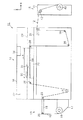
図1に示すように、液体噴射装置としてのインクジェット式プリンタ11は、ターゲットとしての長尺状の連続紙12を繰り出す繰り出し部13と、該繰り出し部13から繰り出された連続紙12に順次印刷を行う本体部14と、該本体部14で印刷が行われた連続紙12を巻き取る巻き取り部15とを備えている。すなわち、本体部14は直方体状の本体ケース16を備えており、連続紙12の搬送方向において上流側となる本体ケース16の左側に繰り出し部13が配設されると共に下流側となる本体ケース16の右側に巻き取り部15が配設されている。
As shown in FIG. 1, an
繰り出し部13は、本体ケース16の左面下端部から左方に延びる支持板17を備えており、該支持板17の左端部には前方(図1において紙面と直交する方向の手前側)に向かって延びる巻き軸18が支持板17に対して回転可能に支持されている。そして、巻き軸18には予めロール状に巻かれた連続紙12が該巻き軸18と一体回転可能に支持されている。なお、本実施形態の連続紙12には、吸水性に乏しい、もしくは撥水性などを有して、着弾したインク(液体)が表面付近で乾燥する用紙が用いられている。
The pay-out
また、繰り出し部13は本体ケース16の左面中央部から左方に向かって水平に延びる平板状の繰り出し台19を備えている。そして、繰り出し台19の先端部には巻き軸18から繰り出される連続紙12を巻き掛けて繰り出し台19の上面に導くための中継ローラ20が回転可能に設けられており、連続紙12は繰り出し台19の上面に沿って右側(本体部14側)に向かって搬送される。
Further, the feeding
本体部14の本体ケース16内における上下方向の中央部よりやや上寄りの位置には、本体ケース16内を上下に区画する平板状の基台21が設けられており、本体ケース16内における基台21よりも上側の領域は連続紙12に印刷を行うための印刷室22となっている。
A
本体ケース16の左壁には繰り出し台19の上面から本体ケース16内に連続紙12を搬入するための図示しない搬入口が設けられており、本体部14には上記搬入口と近傍位置で対向するように搬送手段としての引き込み駆動ローラ23が回転駆動可能に設けられている。なお、引き込み駆動ローラ23の回転駆動は、図示しない制御装置の制御信号に基づき制御される。
On the left wall of the
また、本体ケース16内における引き込み駆動ローラ23の右斜め下方には中継ローラ25が回転可能に設けられている。そして、引き込み駆動ローラ23の駆動によって本体ケース16内に引き込まれた連続紙12は、印刷室22の左端部寄りの位置に向かうように中継ローラ25に巻き掛けられている。
Further, a
印刷室22内における中継ローラ25の右斜め上方には中継ローラ26が設けられており、該中継ローラ26には連続紙12が左側下方から巻き掛けられて右方向に水平に搬送されるようになっている。
A
印刷室22内における中継ローラ26の右側の領域には、基台21上に支持された矩形板状の第1の支持部材としてのプラテン27が設けられている。また、プラテン27上には矩形状の第2の支持部材としてのカバー部材54が積層状態に固定されている。なお、このカバー部材54の具体的構成については後述する。プラテン27の右側には、該プラテン27を挟んで中継ローラ26と対向するように転換ローラ28が設けられている。この場合、中継ローラ26の上面、カバー部材54の上面、及び転換ローラ28の上面は、互いに同一高さで同一平面内に位置するようになっている。
A
転換ローラ28には中継ローラ26からプラテン27の上面に沿って水平右方向に搬送される連続紙12が左側上方から巻き掛けられて連続紙12の搬送方向が水平右方向から鉛直下方向に転換されている。そして、転換ローラ28によって搬送方向が鉛直下方向に転換された連続紙12は、基台21に設けられた図示しない挿通孔を通って鉛直下方に搬送されるようになっている。
The
印刷室22内におけるプラテン27の前後両側には左右方向に延びるガイドレール29(図1では二点鎖線で示す)が対をなすように設けられており、該ガイドレール29の上面はプラテン27上に積層されたカバー部材54の上面よりも高くなっている。両ガイドレール29の上面には、矩形板状のキャリッジ30が該両ガイドレール29に沿って左右方向へ往復移動可能な状態で支持されている。そして、キャリッジ30は、制御装置(図示略)の制御信号に基づき両ガイドレール29上を左右方向に移動するようになっている。
Guide rails 29 (indicated by a two-dot chain line in FIG. 1) extending in the left-right direction are provided on both the front and rear sides of the
そして、キャリッジ30の下面には、図示しないスライド板がキャリッジ30に対して前後方向にスライド移動可能に支持されている。スライド板の下面には、液体噴射ヘッドとしての記録ヘッド31が支持されている。また、印刷室22内における本体ケース16の上壁には、インクを一時貯留するためのバルブユニット34が設けられている。各バルブユニット34には、互いに色の異なるインクが一時貯留されている。
A slide plate (not shown) is supported on the lower surface of the
そして、各バルブユニット34は、記録ヘッド31とそれぞれ図示しないインク供給チューブを介して接続されており、該各インク供給チューブを介して記録ヘッド31に各インクを供給するようになっている。記録ヘッド31の下面には図示しない複数のノズル開口が設けられており、各バルブユニット34から供給されたインクを該各ノズル開口からプラテン27上に搬送されて停止された状態の連続紙12に向かって噴射することで印刷が行われるようになっている。
Each
したがって、連続紙12の搬送経路の途中位置であって連続紙12の印刷が行われるプラテン27の左端から右端までの領域は印刷領域Aとされており、連続紙12は該連続紙12の搬送経路を印刷領域Aと対応した領域単位で間欠的に搬送されるようになっている。
Therefore, the area from the left end to the right end of the
そして、記録ヘッド31は、キャリッジ30の左右方向への移動に伴って連続紙12の印刷領域Aを左右方向に移動しながらインクを噴射すると共に、スライド板によって前後方向に位置をずらすことにより移動経路を変更して印刷領域Aの全域に対してインクを噴射するようになっている。
The
図1に示すように、転換ローラ28に巻き掛けられて鉛直下方向に搬送された連続紙12は、本体ケース16内における転換ローラ28の鉛直下方となる位置に回転可能に配設された反転ローラ38に左側上方から巻き掛けられ、やや右斜め上方に向かって搬送される。そして、反転ローラ38から搬送された連続紙12は、本体ケース16内における反転ローラ38の右方に回転可能に設けられた中継ローラ39に左側下方から巻き掛けられ、本体ケース16内を本体ケース16の右壁に沿うように上方に向かって搬送される。なお、印刷領域Aに印刷が施された後の連続紙12は、本体ケース16内を搬送される過程で自然乾燥されることとなる。
As shown in FIG. 1, the
また、本体ケース16の右壁における基台21の近傍位置には連続紙12を巻き取り部15側へ搬出するための図示しない搬出口が設けられると共に、本体ケース16内における上記搬出口と近傍位置で対向するように搬送手段としての送り出し駆動ローラ40が回転駆動可能に設けられている。そして、制御装置(図示略)の制御信号に基づいて送り出し駆動ローラ40を駆動することで、連続紙12が上記搬出口を介して巻き取り部15側へ送り出されるようになっている。
Further, an unillustrated unloading port for unloading the
巻き取り部15は、直方体状の巻き取りフレーム41を備えており、巻き取りフレーム41の高さは送り出し駆動ローラ40の高さとほぼ同じになっている。また、巻き取りフレーム41の上端部には中継ローラ42が回転可能に設けられており、上記搬出口から送り出された連続紙12は、中継ローラ42に左側上方から巻き掛けられ、右斜め下方に向けて搬送される。
The winding
巻き取りフレーム41における中継ローラ42の右斜め下方には前方に向かって延びる搬送手段としての巻き取り駆動軸43が巻き取りフレーム41に対して回転駆動可能に支持されている。巻き取り駆動軸43には中継ローラ42から右斜め下方に向かって搬送された連続紙12が巻き付けられており、制御装置(図示略)の制御信号に基づき該巻き取り駆動軸43を回転駆動することで巻き取り駆動軸43に連続紙12が順次巻き取られるようになっている。
A take-up
次に、プラテン27の構成について図2に基づき以下説明する。
図2に示すように、プラテン27には、該プラテン27を上下方向(プラテン27の厚み方向)に貫通する多数の第1の吸引孔としての吸引孔44が形成されている。すなわち、吸引孔44は、プラテン27の上側の面となる表面27a、及び下側の面となる裏面27b(図3参照)上に開口するように形成される。なお、吸引孔44における表面27a側及び裏面27b側の各開口径は等しくなっているため、各開口断面積も等しくなっている。
Next, the configuration of the
As shown in FIG. 2, the
さらに、各吸引孔44は、複数(図2では16個)の吸引孔44が前後方向に沿う複数列の吸引孔列45を左右方向に所定間隔をおいて形成するように規則的に配列されている。また、プラテン27の下側(即ち、プラテン27と基台21との間の領域)には、各吸引孔44内の空気を吸引するための吸引手段としてのファン46が裏面27bに形成された吸引孔44の開口を囲繞する囲い部材(図示略)と共に設けられている。そして、各ファン46を駆動することで各吸引孔44内に負圧が発生するようになっている。
Further, each
次に、上記プラテン27を加熱するための加熱装置について図2に基づき以下説明する。
図2に示すように、加熱装置47は、プラテン27内に埋設される加熱手段としての複数(本実施形態では3つ)のヒータ48,49,50と、各ヒータ48,49,50に発熱させるべくヒータ48,49,50毎に個別に電流を供給するための装置本体51とを備えている。これら各ヒータ48,49,50は、それぞれ同じ形状をしており、プラテン27内において左右方向に並ぶように(即ち、左右方向における位置が異なるように)配置されている。そして、装置本体51から個別に電流が供給されることにより各ヒータ48,49,50はそれぞれ発熱するようになっている。また、プラテン27は、各ヒータ48,49,50からの熱量を保持し、連続紙12に付着したインクの乾燥を促進させるに十分な厚み(本実施形態では約25mm)を有するように構成されている。
Next, a heating apparatus for heating the
As shown in FIG. 2, the
各ヒータ48,49,50は、一本の長尺部材の複数箇所に曲げ加工を施すことによりそれぞれ形成されている。すなわち、各ヒータ48,49,50は、前後方向に延びると共に、左右方向において互いに隣り合う吸引孔列45間毎に配置される複数(本実施形態では6つ)の第1加熱部52と、左右方向において一つの吸引孔列45を挟んだ配置態様の第1加熱部52同士を連結するための複数(本実施形態では5つ)の第2加熱部53とを備えた構成とされている。
Each
各第1加熱部52は、それぞれの前後方向における長さが吸引孔列45の前後方向における長さよりも長くなるようにそれぞれ形成されている。また、各第1加熱部52は、左右両側に位置する両吸引孔列45の左右方向における中央にそれぞれ配置されている。
Each
そのため、プラテン27においては、各吸引孔44が貫通形成された領域(以下、「低温領域」という。)の温度と、各吸引孔44が貫通形成されていない領域(以下、「高温領域」という。)の温度との間に温度差ができることになる。
Therefore, in the
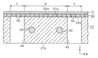
図2及び図3に示すように、プラテン27の上には、矩形状の第2の支持部材としてのカバー部材54が、該プラテン27の表面27aを覆うように積層されて、複数(本実施形態では6本)のビス55により固定されている。そして、プラテン27上に搬送される連続紙12は、カバー部材54の上側の面となる支持面54aに支持されるようになっている。なお、前述したように、カバー部材54の支持面54aと、中継ローラ26の上面及び転換ローラ28の上面は、互いに同一高さで同一平面内に位置するようになっている。
As shown in FIGS. 2 and 3, a
カバー部材54は、剛性を有して熱伝導率が高い金属(本実施形態ではアルミニウム)製の板材であり、該カバー部材54には、その支持面54aと下面54bとに開口を形成するように多数の第2の吸引孔としての貫通孔56が上下方向(カバー部材54の厚み方向)に打抜形成されている。
The
貫通孔56の支持面54a側と下面54b側の開口の口径は等しくなっており、該貫通孔56の開口断面積(本実施形態では開口径が約0.5mm)は、吸引孔44の開口断面積(本実施形態では開口径が約4mm)よりも小さくなっている。さらに、隣り合う貫通孔56同士の間隔(ピッチ)は、隣り合う吸引孔44同士の間隔(ピッチ)よりも狭くなっている。
The diameters of the openings on the
そして、カバー部材54とプラテン27とは、カバー部材54の下面54bとプラテン27の表面27aとが面接触した状態で固着された際に1つの吸引孔44と複数の貫通孔56とが連通するようになっている。そして、ファン46の駆動に伴って各吸引孔44内に発生した負圧は、該吸引孔44とそれぞれ連通する貫通孔56内に伝達されると共に、該負圧の発生によりプラテン27及びカバー部材54越しに各吸引孔44及び貫通孔56を介して連続紙12が吸引され、カバー部材54の支持面54aに連続紙12が吸着されるようになっている。なお、図3では吸引孔44及び貫通孔56の開口径の比較を容易にするために、吸引孔44及び貫通孔56を誇張して図示している。
When the
また、カバー部材54の厚み(本実施形態では約0.4mm)は、メッシュ状の加工を可能とする程度に薄くなっていると共に、貫通孔56内に負圧が発生した際にも支持面54aの平面性が保たれるようになっている。そして、ヒータ48,49,50が加熱されてプラテン27が暖められると、カバー部材54と接触するプラテン27の高温領域から該カバー部材54へ熱が伝達されると共に、カバー部材54上に位置する連続紙12にも熱が伝達されるようになっている。
In addition, the thickness of the cover member 54 (about 0.4 mm in the present embodiment) is thin enough to enable mesh processing, and the support surface even when negative pressure is generated in the through
ここで、カバー部材54は、熱伝導効率の良い金属によって形成されているため、該カバー部材54において、プラテン27の低温領域となる吸引孔44上に位置する領域にも熱は伝達され、カバー部材54全体が略同じ温度に暖められる。すなわち、連続紙12では、非接触領域Cがカバー部材54上に位置して直接熱が伝えられる領域と該領域よりも熱が伝えられない領域に分断される。そのため、連続紙12上に付着したインクには、非接触領域Cにおいて、カバー部材54の支持面54aと接触して乾燥が促進される領域に向かうような流れが生じることとなるが、この領域は非接触領域Cに比べて狭いので発生する色むら(濃淡)の発生が抑制される。
Here, since the
本実施形態では、以上のようなプラテン27、ファン46、カバー部材54によってターゲット支持装置としての連続紙支持装置57が構成されている。また、該連続紙支持装置57、引き込み駆動ローラ23,送り出し駆動ローラ40,巻き取り駆動軸43によってターゲット搬送装置が構成されている。
In the present embodiment, the
次に、インクジェット式プリンタ11の作用について、ヒータ48,49,50により加熱されたプラテン27上において、連続紙12に付着したインクを乾燥させる際の作用を中心に記載する。なお、プラテン27上に配置される連続紙12は、その前後方向における両端部(両縁部)がカバー部材54よりも内側に位置するものとする。
Next, the action of the
さて、インクジェット式プリンタ11による連続紙12に対する印刷が開始される場合、印刷領域Aに搬送された連続紙12は、プラテン27の下方に配置された各ファン46が駆動することにより、各吸引孔44内の空気が吸引される。すると、貫通孔56を介して連続紙12のうちカバー部材54に支持される部分が、カバー部材54の支持面54aに吸着される。
When printing on the
また、装置本体51の駆動に基づきヒータ48,49,50が発熱すると、カバー部材54にはプラテン27を介してヒータ48,49,50の熱が伝えられる。
連続紙12のうちプラテン27上に位置する部分に対して印刷が実行される(即ち、上下方向及び左右方向に移動する記録ヘッド31からインクが噴射される)と、連続紙12に着弾したインクは、連続紙12に浸透せずに表面付近に留まる。そのため、プラテン27に連続紙12が吸着された状態のまま、インクはプラテン27及びカバー部材54を介して付与された熱に基づいて、先に着弾したインクからインク溶媒(例えば、水や有機溶剤)が蒸発する。このとき、非接触領域Cにおいてインクの流れる範囲が狭くなっているため、非接触領域Cにおいてインクの流れが生じたとしても、その流れる範囲は狭いものとなる。したがって、印刷領域A内に噴射されたインクは、非接触領域Cから接触領域Bに向かう大きな流れの発生が抑えられる。そのため、インク中の色素成分(例えば、顔料や染料)は、噴射された位置もしくは該噴射された位置から若干ずれた位置において定着することになる。
Further, when the
When printing is performed on a portion of the
その後、印刷領域Aへの印刷が完了すると、図示しない制御装置によって、ファン46の駆動が停止されて連続紙12のカバー部材54への吸着状態が解除されると共に、引き込み駆動ローラ23、送り出し駆動ローラ40、巻き取り駆動軸43が駆動されて、連続紙12は巻き取り部15側に搬送される。
Thereafter, when the printing in the printing area A is completed, the driving of the
上記第1の実施形態によれば、以下のような効果を得ることができる。
(1)吸引孔44が形成されたプラテン27上に、吸引孔44よりも開口断面積の小さな貫通孔56が形成されたカバー部材54を積層状態で固定し、該カバー部材54により連続紙12を支持する構成となっている。そのため、連続紙12においてカバー部材54における1つの貫通孔56上に位置する領域を、プラテン27によって直接連続紙12を支持するとした場合のプラテン27における1つの吸引孔44上に位置する領域(非接触領域C)よりも狭くすることができる。すなわち、連続紙12に付着したインクの流れは、乾燥速度の遅い領域において、乾燥速度の速い領域に向かって生じるため、カバー部材54によって非接触領域Cを小さく分割することで、インクの流れる範囲を小さくすることができる。そのため、溶液とともに移動する溶媒の移動を狭い範囲で限定することにより、乾燥後の連続紙12に現れる濃淡を目立たなくすることができ、画像品質の低下を抑制することができる。
According to the first embodiment, the following effects can be obtained.
(1) A
(2)プラテン27に剛性を有したカバー部材54を固着することで、プラテン27の剛性を補うと共に、連続紙12をカバー部材54上に安定的に支持することができる。
(3)1つの吸引孔44に対して複数の貫通孔56を連通させることにより、吸引孔44及び該吸引孔44と連通する貫通孔56全体の流路抵抗を、吸引孔44と貫通孔56とを1対1で連通させる場合と比べて小さくすることができる。そのため、吸引能力の低い吸引手段を用いた場合でも、連続紙12に対して十分な吸引力を付与することができる。
(2) By fixing the
(3) By connecting a plurality of through
(4)一般に、厚みを有する部材ほど小さな孔を形成するのは困難である。それに対し、カバー部材54の厚みが薄いため、開口断面積が小さな貫通孔56を容易に形成することができる。さらに、貫通孔56の開口断面積が小さくても、該貫通孔56の長さが厚みに合わせて短くなるため、貫通孔56の流路抵抗を小さくすることができる。
(4) In general, it is more difficult to form a smaller hole as a member having a thickness. On the other hand, since the
(5)ヒータ48,49,50によりプラテン27が加熱されると、連続紙12はカバー部材54を介して熱を受けるため該連続紙12に付着したインクの乾燥が促進される。このとき、連続紙12においてプラテン27の吸引孔44が形成されていない領域(接触領域B)と非接触領域Cとの温度差が大きくなるため、連続紙12のインクの付着面と平行な方向へインクは流れやすくなる。しかし、この流れはカバー部材54によって狭い範囲に限定されているため、画像品質の低下を抑制することができる。
(5) When the
(6)カバー部材54を熱伝導性に優れた金属により形成することで、ヒータ48,49,50によって加熱されたプラテン27の熱をカバー部材54を介して効率よく連続紙12に伝達することができる。さらに、吸引孔44上に位置するカバー部材54へ熱が伝達されやすくなるため、非接触領域Cに付着したインクの乾燥を促進させることができる。
(6) By forming the
(7)引き込み駆動ローラ23、送り出し駆動ローラ40、巻き取り駆動軸43によって搬送方向の上流側から下流側に向けて搬送される連続紙12は、プラテン27に積層状態で固定されたカバー部材54上において吸着状態で支持される。そして、カバー部材54上に吸着状態で支持された連続紙12に対してインクが噴射され、その後、搬送手段が連続紙12を下流側へ搬送する。そのため、連続紙12の画像品質を良好に維持するインクの乾燥と搬送を連続して行うことができる。
(7) The
(8)記録ヘッド31は、カバー部材54上に吸着状態で支持されて停止した連続紙12に対してインクを噴射する。すなわち、記録ヘッド31がインクを連続紙12に噴射する間、連続紙12はカバー部材54上に吸着された状態となっているため、先に連続紙12に噴射されたインクから蒸発する。このとき、連続紙12における非接触領域Cで生じる連続紙12のインクが付着した面と平行な方向で生じるインクの流れは狭い範囲に限定されるため、連続紙12がプラテン27及びカバー部材54上に滞留する時間が長く、その分多くの溶媒成分が蒸発した場合でも、溶質の偏りを抑えて画像品質の低下を抑制することができる。
(8) The
(第2の実施形態)
次に、本発明の第2の実施形態を図4,図5に従って説明する。なお、第2の実施形態は、第1の実施形態とはプラテン27の表面形状を変更した点でのみ構成が相違しており、その他の構成は共通しているため、同様の構成部分については同一符号を付すことにして、その詳細な重複説明を省略する。
(Second Embodiment)
Next, a second embodiment of the present invention will be described with reference to FIGS. The second embodiment is different from the first embodiment only in that the surface shape of the
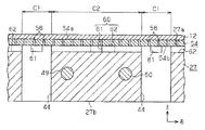
図4に示すように、プラテン27の表面27aには、該表面27aに開口する吸引孔44に連通するように溝状の凹部60が形成されている。すなわち、凹部60は、各吸引孔列45を構成する吸引孔44同士を連通させるように前後方向に沿って形成された複数の第1の凹部61と、左右方向に隣り合う吸引孔44同士を連通させるように左右方向に沿って形成された複数の第2の凹部62によって格子状に形成されている。
As shown in FIG. 4, a groove-
そして、第1の凹部61の幅と第2の凹部62の幅は、それぞれカバー部材54に形成された貫通孔56の開口径よりも大きく、且つ吸引孔44の開口径よりも小さくなっている。
The width of the
そのため、図5に示すように、プラテン27の表面27a側に積層状態にカバー部材54を固定すると、凹部60の開口がカバー部材54によって閉塞されると共に、凹部60上に位置する貫通孔56が凹部60を介して複数の吸引孔44と連通する。そのため、ファン46の駆動に伴って各吸引孔44内に発生した負圧は、該吸引孔44上に形成された貫通孔56、及び凹部60を介して連通する貫通孔56内に伝達される。なお、図5では吸引孔44、貫通孔56、凹部60の開口径及び開口幅の比較を容易にするために、吸引孔44、貫通孔56、凹部60を誇張して図示している。
Therefore, as shown in FIG. 5, when the
また、カバー部材54は、熱伝導性の良い金属によって形成されている。そのため、ヒータ48,49,50が加熱されてプラテン27が暖められると、該カバー部材54において、プラテン27の低温領域となる吸引孔44上に位置する領域と同様に、凹部60上に位置する領域にも熱は伝達され、カバー部材54全体が略同じ温度に暖められる。
The
すなわち、連続紙12では、吸引孔44上に位置する第1の非接触領域C1及び凹部60上に位置する第2の非接触領域C2において、カバー部材54上に位置して直接熱が伝えられる領域と、貫通孔56上に位置してカバー部材54から直接熱が伝えられない領域に分断される。そのため、連続紙12上に付着したインクには、第1の非接触領域C1及び第2の非接触領域C2において、貫通孔56上に位置する領域では、カバー部材54の支持面54aと接触して乾燥が促進される領域に向かうような流れが生じることとなるが、この領域は第1の非接触領域C1及び第2の非接触領域C2に比べて狭いので、色むら(濃淡)の発生が抑制される。
In other words, in the
次に、本実施形態のインクジェット式プリンタ11の作用について、ファン46の駆動に伴って支持面54a上に吸着される連続紙12にインクを付着させて乾燥させる際の作用を中心に記載する。なお、プラテン27上に配置される連続紙12は、その前後方向における両端部(両縁部)がカバー部材54の両端部よりも内側に位置するものとする。
Next, the operation of the
さて、印刷領域Aに連続紙12が搬送された状態で各ファン46を駆動すると、各吸引孔44内の空気が吸引される。すると、吸引孔44上に位置する貫通孔56、及び凹部60を介して吸引孔44と連通する貫通孔56内が吸引されて、連続紙12における第1の非接触領域C1と第2の非接触領域C2とに吸引力が付与される。
Now, when each
すなわち、連続紙12は、該連続紙12において吸引力が作用する面積が、吸引孔44上に位置する貫通孔56によって第1の非接触領域C1にのみ吸引力を作用させる場合に比べて大きい。そのため、例えば、加熱された連続紙12が膨張した場合であっても、該連続紙12は支持面54aからのうき上がりが抑制されてより安定した状態で支持される。
That is, the
また、装置本体51の駆動に基づきヒータ48,49,50が発熱すると、カバー部材54にはプラテン27を介してヒータ48,49,50の熱が伝えられる。そして、カバー部材54を介して該カバー部材54上に支持された連続紙12が加熱された状態において、記録ヘッド31からインクが噴射されると、連続紙12に先に着弾したインクからインク溶媒が蒸発する。
Further, when the
このとき、第1の非接触領域C1と第2の非接触領域C2において、貫通孔56上に位置してインクの流れる範囲が、第1の非接触領域C1及び第2の非接触領域C2に比べて狭くなっている。そのため、第1の非接触領域C1及び第2の非接触領域C2においてインクの流れが生じたとしても、その流れる範囲は狭いものとなる。したがって、印刷領域A内に噴射されたインクは、第1の非接触領域C1及び第2の非接触領域C2から接触領域Bに向かう大きな流れの発生が抑制される。そのため、インク中の色素成分は、噴射された位置もしくは、該噴射された位置から若干ずれた位置において定着することになる。
At this time, in the first non-contact region C1 and the second non-contact region C2, the range where the ink flows is located on the through
上記第2の実施形態によれば、第1の実施形態における(1)〜(8)の効果に加えて、さらに以下のような効果を得ることができる。
(9)プラテン27の表面27aに吸引孔44と連通する凹部60を形成することにより、吸引孔44と連通する貫通孔56を増やすことができる。すなわち、ファン46が吸引孔44内を吸引すると、凹部60を介して吸引孔44と連通する貫通孔56内が吸引される。したがって、連続紙12に吸引力を及ぼす貫通孔56の数を容易に増やすことができ、連続紙12においてより広い領域に吸引力を作用させて支持面54aからの連続紙12のうき上がりを抑制することができる。
According to the said 2nd Embodiment, in addition to the effect of (1)-(8) in 1st Embodiment, the following effects can be acquired further.
(9) By forming the
(10)プラテン27の表面27aに形成された凹部60は、複数の吸引孔44に連通している。そのため、プラテン27の表面27a側に固定されるカバー部材54に形成された貫通孔56は、凹部60を介して複数の吸引孔44に連通する。したがって、凹部60を介して吸引される貫通孔56において吸引力のばらつきを抑制することができる。
(10) The
なお、上記実施形態は以下のように変更してもよい。
・上記実施形態において、記録ヘッド31からのインクの噴射によらずに孔版印刷等の他の印刷処理により表面にインクが付着した連続紙12をプラテン27上に搬送して乾燥させるようにしてもよい。
In addition, you may change the said embodiment as follows.
In the above-described embodiment, the
・上記実施形態において、引き込み駆動ローラ23,送り出し駆動ローラ40,巻き取り駆動軸43を用いずに、手動で連続紙12をプラテン27及びカバー部材54上に位置させるようにしてもよい。また、矩形状の用紙をベルト上に載置してプラテン27及びカバー部材54上を搬送するようにしてもよい。
In the above-described embodiment, the
・上記実施形態において、カバー部材54はアルミニウムや鉄、銅、それらの合金といった金属に限らず、貫通孔56を形成することができれば樹脂やガラス製でもよい。なお、カバー部材54は熱伝導性に優れた材料で構成するのが好ましいが、スポンジやフェルトのような通気性を有する材料を用いてもカバー部材54上に連続紙12を吸着保持しつつ、非接触領域Cの中央部から接触領域Bとの境界付近へ向かうインクの大きな流れを抑制することができる。なお、弾性を有するスポンジを用いる場合には、吸引孔44内の負圧がスポンジ内で分散されて連続紙12へ作用する力が、スポンジを変形させない程度の力であることが望ましい。
In the above embodiment, the
・上記実施形態において、ヒータ48,49,50を設けない構成としてもよい。すなわち、ファン46を吸引駆動すると吸引孔44を通過する空気によって熱が奪われる。そのため、プラテン27において吸引孔44及び該吸引孔44付近の温度と、吸引孔44から離れた領域では温度差が生じる。そのため、カバー部材54を介して連続紙12を支持することで、この温度差に基づいて生じる濃淡を抑制することができる。
In the above embodiment, the
・上記実施形態において、プラテン27とカバー部材54とが、連続紙12に付着したインクを乾燥させることができる程度の熱量を保持することができれば、カバー部材54の厚みをプラテン27の厚みよりも厚くしてもよい。すなわち、プラテン27とカバー部材54の双方でヒータ48,49,50の熱量を保存する。さらに、プラテン27とカバー部材54を積層して厚みを稼いでいるため、1枚のプラテン27に貫通孔56を形成するのに比べてカバー部材54へ貫通孔56を容易に形成することができる。
In the above embodiment, if the
・上記第1の実施形態において、カバー部材54には、吸引孔44と同じピッチで貫通孔56を形成するようにしてもよい。このようなカバー部材54をプラテン27上に積層すると、吸引孔44には、1つの貫通孔56が連通することになり、該貫通孔56を介して連続紙12を支持面54a上に吸着することができる。また、積層した際に吸引孔44上に位置する領域にのみ貫通孔56を形成してもよい。これにより、形成する貫通孔56の数を減らすことができるため、カバー部材54の形成を容易にすることができる。
In the first embodiment, the
・上記第2の実施形態において、カバー部材54には、該カバー部材54をプラテン27上に積層した際に、吸引孔44及び凹部60上に位置する領域にのみ貫通孔56を形成してもよい。これにより、形成する貫通孔56の数を減らすことができるため、カバー部材54の形成を容易にすることができる。
In the second embodiment, when the
・上記実施形態において、カバー部材54の下面54b側に、貫通孔56同士を連通する凹部を形成してもよい。これにより、吸引孔44内に発生させた負圧をより多くの貫通孔56へ作用させることができるため、連続紙12をより安定的に支持面54aに吸着することができる。
In the embodiment described above, a recess that allows the through
・上記実施形態において、カバー部材54を金属板に多数の貫通孔56を打抜形成したパンチングメタルとしたが、針金を編むもしくは織ることで形成された通気性を有する金網としてもよい。このとき、針金と針金との隙間が吸引孔44の開口断面積よりも小さくなっている。
In the above embodiment, the
・上記実施形態において、ターゲットには、樹脂製、金属製といった吸水性を有しないシートを用いることもできる。
・上記実施形態において、吸引手段は、ファン46に限らず、プラテン27の下面側から吸引孔44内に負圧を発生させるポンプを用いてもよい。
In the above embodiment, a sheet that does not have water absorption, such as resin or metal, can be used as the target.
In the above embodiment, the suction unit is not limited to the
・上記第2の実施形態において、凹部60は、1つの吸引孔44に連通するように形成してもよい。
・上記第2の実施形態において、凹部60が形成される方向は、前後方向又は左右方向に限らず、斜め方向に沿って延びるように形成してもよい。また、凹部60の形状は、渦巻き形状や環状としてもよい。さらに、吸引孔44の開口縁に沿って窪みを形成し、平面視円形状、楕円形状、矩形状などの凹部を形成してもよい。
In the second embodiment, the
In the second embodiment, the direction in which the
・上記第2の実施形態において、凹部60は、断面視矩形状に限らず、壁面を斜めに形成した断面視三角形状のV字溝としてもよい。また、凹部60の断面視形状は、半円形、楕円形など任意に設定することができる。
In the second embodiment, the
・上記実施形態では、液体噴射装置をインクジェット式プリンタ11に具体化したが、インク以外の他の液体を噴射したり吐出したりする液体噴射装置を採用してもよい。微小量の液滴を吐出させる液体噴射ヘッド等を備える各種の液体噴射装置に流用可能である。なお、液滴とは、上記液体噴射装置から吐出される液体の状態をいい、粒状、涙状、糸状に尾を引くものも含むものとする。また、ここでいう液体とは、液体噴射装置が噴射させることができるような材料であればよい。例えば、物質が液相であるときの状態のものであればよく、粘性の高い又は低い液状体、ゾル、ゲル水、その他の無機溶剤、有機溶剤、溶液、液状樹脂、液状金属(金属融液)のような流状態、また物質の一状態としての液体のみならず、顔料や金属粒子などの固形物からなる機能材料の粒子が溶媒に溶解、分散又は混合されたものなどを含む。また、液体の代表的な例としては上記実施形態で説明したようなインクや液晶等が挙げられる。ここで、インクとは一般的な水性インク及び油性インク並びにジェルインク、ホットメルトインク等の各種液体組成物を包含するものとする。液体噴射装置の具体例としては、例えば液晶ディスプレイ、EL(エレクトロルミネッセンス)ディスプレイ、面発光ディスプレイ、カラーフィルタの製造などに用いられる電極材や色材などの材料を分散又は溶解のかたちで含む液体を噴射する液体噴射装置、バイオチップ製造に用いられる生体有機物を噴射する液体噴射装置、精密ピペットとして用いられ試料となる液体を噴射する液体噴射装置、捺染装置やマイクロディスペンサ等であってもよい。さらに、時計やカメラ等の精密機械にピンポイントで潤滑油を噴射する液体噴射装置、光通信素子等に用いられる微小半球レンズ(光学レンズ)などを形成するために紫外線硬化樹脂等の透明樹脂液を基板上に噴射する液体噴射装置、基板などをエッチングするために酸又はアルカリ等のエッチング液を噴射する液体噴射装置を採用してもよい。そして、これらのうちいずれか一種の液体噴射装置に本発明を適用することができる。
In the above embodiment, the liquid ejecting apparatus is embodied in the
11…インクジェット式プリンタ(液体噴射装置)、12…連続紙(ターゲット)、23…引き込み駆動ローラ(搬送手段)、27…プラテン(第1の支持部材)、27a…表面、27b…裏面、31…記録ヘッド(液体噴射ヘッド)、40…送り出し駆動ローラ(搬送手段)、43…巻き取り駆動軸(搬送手段)、44…吸引孔(第1の吸引孔)、46…ファン(吸引手段)、48,49,50…ヒータ(加熱手段)、54…カバー部材(第2の支持部材),54a…支持面、56…貫通孔(第2の吸引孔)、57…連続紙支持装置(ターゲット支持装置)、60…凹部。
DESCRIPTION OF
Claims (8)
前記第1の吸引孔よりも開口断面積が小さな第2の吸引孔が複数形成されると共に、前記第1の支持部材の表面側に積層状態に固定される第2の支持部材と、
前記複数の第1の吸引孔内を吸引して該各第1の吸引孔と連通する前記第2の吸引孔内を吸引するための吸引手段と
を備え、
前記凹部は、複数の前記第1の吸引孔同士を連通させるとともに、前記凹部の幅は、前記第2の吸引孔の開口径よりも大きく、且つ前記第1の吸引孔の開口径よりは小さくなっており、
前記吸引手段を駆動させることにより、前記第2の支持部材の支持面上に液体を付着可能に支持されたターゲットを吸着保持することを特徴とするターゲット支持装置。 A plurality of first suction holes are formed so as to open on the front surface and the back surface, and a first support member in which a groove-like recess communicating with the first suction holes is formed on the front surface;
A plurality of second suction holes having a smaller opening cross-sectional area than the first suction holes, and a second support member fixed in a stacked state on the surface side of the first support member;
A suction means for sucking the inside of the plurality of first suction holes and sucking the inside of the second suction holes communicating with the first suction holes;
The recess allows the plurality of first suction holes to communicate with each other, and the width of the recess is larger than the opening diameter of the second suction hole and smaller than the opening diameter of the first suction hole. And
Wherein the suction means by driving, target support apparatus characterized by a holding suction the second targets that are attached supporting the liquid on the support surface of the support member.
請求項1〜請求項6のうち何れか一項に記載のターゲット支持装置とを備えたターゲット搬送機構。 Transport means for transporting the target from the upstream side in the transport direction to the downstream side of the first support member and the second support member;
A target transport mechanism comprising the target support device according to any one of claims 1 to 6 .
請求項1〜請求項6のうち何れか一項に記載のターゲット支持装置又は請求項7に記載のターゲット搬送機構を備えた液体噴射装置。 A liquid ejecting head that ejects liquid onto a target supported on a support surface of the second support member;
A liquid ejecting apparatus having a target transport mechanism according to the target support apparatus or claim 7 according to any one of claims 1 to 6.
Priority Applications (5)
| Application Number | Priority Date | Filing Date | Title |
|---|---|---|---|
| JP2009186811A JP5482012B2 (en) | 2008-09-19 | 2009-08-11 | Target support device, target transport mechanism, and liquid ejection device |
| US12/562,365 US8636355B2 (en) | 2008-09-19 | 2009-09-18 | Target supporting apparatus, target transporting mechanism and liquid ejecting apparatus |
| CN201110281282.3A CN102431322B (en) | 2008-09-19 | 2009-09-21 | Target supporting apparatus, target transporting mechanism and liquid ejecting apparatus |
| CN2009101746526A CN101676114B (en) | 2008-09-19 | 2009-09-21 | Object supporting device, object conveying mechanism and liquid injection device |
| US14/073,720 US9315048B2 (en) | 2008-09-19 | 2013-11-06 | Liquid ejecting apparatus |
Applications Claiming Priority (3)
| Application Number | Priority Date | Filing Date | Title |
|---|---|---|---|
| JP2008241438 | 2008-09-19 | ||
| JP2008241438 | 2008-09-19 | ||
| JP2009186811A JP5482012B2 (en) | 2008-09-19 | 2009-08-11 | Target support device, target transport mechanism, and liquid ejection device |
Publications (3)
| Publication Number | Publication Date |
|---|---|
| JP2010094976A JP2010094976A (en) | 2010-04-30 |
| JP2010094976A5 JP2010094976A5 (en) | 2012-09-27 |
| JP5482012B2 true JP5482012B2 (en) | 2014-04-23 |
Family
ID=42028894
Family Applications (1)
| Application Number | Title | Priority Date | Filing Date |
|---|---|---|---|
| JP2009186811A Active JP5482012B2 (en) | 2008-09-19 | 2009-08-11 | Target support device, target transport mechanism, and liquid ejection device |
Country Status (3)
| Country | Link |
|---|---|
| US (2) | US8636355B2 (en) |
| JP (1) | JP5482012B2 (en) |
| CN (2) | CN101676114B (en) |
Families Citing this family (21)
| Publication number | Priority date | Publication date | Assignee | Title |
|---|---|---|---|---|
| DE102010060489B4 (en) | 2010-11-11 | 2018-08-16 | Océ Printing Systems GmbH & Co. KG | Apparatus for drying an ink-printed record carrier in a printer and method therefor |
| JP5708076B2 (en) * | 2011-03-15 | 2015-04-30 | セイコーエプソン株式会社 | Recording device |
| JP5736926B2 (en) * | 2011-04-15 | 2015-06-17 | セイコーエプソン株式会社 | Printing device |
| US20140049590A1 (en) * | 2011-04-27 | 2014-02-20 | Konica Minolta, Inc. | Inkjet recording device |
| US20130171351A1 (en) * | 2011-07-18 | 2013-07-04 | Camtek Ltd. | Vacuum table for a printing device |
| EP2773509B1 (en) * | 2011-10-31 | 2016-08-03 | Hewlett-Packard Development Company, L.P. | Cover for a printer platen |
| JP6056395B2 (en) * | 2012-11-12 | 2017-01-11 | セイコーエプソン株式会社 | Liquid ejector |
| JP6213733B2 (en) * | 2014-01-30 | 2017-10-18 | セイコーエプソン株式会社 | Liquid ejection device |
| JP6454996B2 (en) * | 2014-07-01 | 2019-01-23 | セイコーエプソン株式会社 | Liquid ejection device |
| CN113248975B (en) | 2014-10-24 | 2023-06-16 | 精工爱普生株式会社 | Inkjet ink composition and inkjet recording method |
| JP6373178B2 (en) * | 2014-11-26 | 2018-08-15 | 株式会社沖データ | Inkjet recording device |
| JP6604000B2 (en) | 2015-02-24 | 2019-11-13 | セイコーエプソン株式会社 | Inkjet ink composition and inkjet recording method |
| JP6604001B2 (en) | 2015-02-24 | 2019-11-13 | セイコーエプソン株式会社 | Inkjet ink composition, inkjet recording method, and ink set |
| JP6065038B2 (en) * | 2015-03-02 | 2017-01-25 | セイコーエプソン株式会社 | Droplet discharge device |
| JP6672825B2 (en) * | 2016-01-20 | 2020-03-25 | セイコーエプソン株式会社 | Printing equipment |
| CN107011739B (en) | 2016-01-27 | 2021-10-08 | 精工爱普生株式会社 | Non-aqueous inkjet composition |
| JP6733189B2 (en) * | 2016-01-28 | 2020-07-29 | セイコーエプソン株式会社 | Ink composition set and recording method |
| JP6517160B2 (en) * | 2016-02-10 | 2019-05-22 | 株式会社沖データ | inkjet printer |
| EP3694555A4 (en) * | 2017-10-09 | 2021-07-07 | Rhodes Pharmaceuticals L.P. | RESINATE-BASED PHARMACEUTICAL COMPOSITIONS AND THEIR MANUFACTURING AND USE PROCESSES |
| JP7456399B2 (en) * | 2021-02-12 | 2024-03-27 | 株式会社村田製作所 | Sheet conveying device |
| CN117601417B (en) * | 2024-01-18 | 2024-05-14 | 杭州云栖交叉技术研究院 | Spray head spraying structure based on rotary printing platform |
Family Cites Families (15)
| Publication number | Priority date | Publication date | Assignee | Title |
|---|---|---|---|---|
| JPH11292342A (en) | 1998-04-10 | 1999-10-26 | Ricoh Co Ltd | Sheet material holding device |
| US6336722B1 (en) * | 1999-10-05 | 2002-01-08 | Hewlett-Packard Company | Conductive heating of print media |
| US6315404B1 (en) * | 1999-12-21 | 2001-11-13 | Hewlett-Packard Company | Heated vacuum platen |
| US6328440B1 (en) * | 2000-01-07 | 2001-12-11 | Hewlett-Packard Company | Buckling control for a heated belt-type media support of a printer |
| US6254092B1 (en) * | 2000-04-17 | 2001-07-03 | Hewlett-Packard Company | Controlling vacuum flow for ink-jet hard copy apparatus |
| DE60024256T2 (en) * | 2000-08-24 | 2006-08-03 | Hewlett-Packard Development Co., L.P., Houston | Clamping device for printers |
| JP2002351082A (en) * | 2001-05-24 | 2002-12-04 | Adtec Engineeng Co Ltd | Substrate stage for exposure equipment |
| JP3785981B2 (en) * | 2001-10-17 | 2006-06-14 | セイコーエプソン株式会社 | RECORDING MEDIUM CONVEYING DEVICE, RECORDING DEVICE PROVIDED WITH THE CONVEYING DEVICE, AND RECORDING MEDIUM SUCTION UNIT IN RECORDING DEVICE |
| EP1304227B1 (en) | 2001-10-17 | 2004-06-02 | Seiko Epson Corporation | Fixed material transportation apparatus and liquid fixing apparatus using the transportation apparatus |
| JP2004216652A (en) | 2003-01-10 | 2004-08-05 | Noritsu Koki Co Ltd | Inkjet printer |
| DE602004012177D1 (en) * | 2003-03-07 | 2008-04-17 | Seiko Epson Corp | Recording material transporting device and recording device |
| DE602005005593T2 (en) * | 2004-10-04 | 2009-04-30 | Oce-Technologies B.V. | Bow handler with backing plate for bow and temperature control system |
| JP2006150723A (en) | 2004-11-29 | 2006-06-15 | Konica Minolta Medical & Graphic Inc | Inkjet printer |
| JP4726225B2 (en) * | 2006-05-18 | 2011-07-20 | 株式会社ミマキエンジニアリング | Printing apparatus, conveying apparatus, and printing method |
| JP2008080526A (en) * | 2006-09-26 | 2008-04-10 | Brother Ind Ltd | Liquid ejector |
-
2009
- 2009-08-11 JP JP2009186811A patent/JP5482012B2/en active Active
- 2009-09-18 US US12/562,365 patent/US8636355B2/en active Active
- 2009-09-21 CN CN2009101746526A patent/CN101676114B/en active Active
- 2009-09-21 CN CN201110281282.3A patent/CN102431322B/en active Active
-
2013
- 2013-11-06 US US14/073,720 patent/US9315048B2/en active Active
Also Published As
| Publication number | Publication date |
|---|---|
| CN101676114A (en) | 2010-03-24 |
| US9315048B2 (en) | 2016-04-19 |
| CN102431322B (en) | 2014-11-26 |
| US20100073450A1 (en) | 2010-03-25 |
| US8636355B2 (en) | 2014-01-28 |
| US20140063164A1 (en) | 2014-03-06 |
| CN101676114B (en) | 2012-07-04 |
| CN102431322A (en) | 2012-05-02 |
| JP2010094976A (en) | 2010-04-30 |
Similar Documents
| Publication | Publication Date | Title |
|---|---|---|
| JP5482012B2 (en) | Target support device, target transport mechanism, and liquid ejection device | |
| JP2009292130A (en) | Liquid injection device | |
| JP2010100014A (en) | Recording apparatus and target drying method | |
| JP5187153B2 (en) | Recording apparatus and recording method in the recording apparatus | |
| JP2017154834A (en) | Conveying apparatus and printing apparatus | |
| JP2011131460A (en) | Fluid jetting apparatus | |
| JP5728798B2 (en) | Recording device | |
| JP2011194797A (en) | Recording apparatus | |
| JP2012192676A (en) | Recording apparatus and recording method | |
| JP5258242B2 (en) | Liquid ejector | |
| US8376504B2 (en) | Fluid ejecting apparatus with humidification member for moisturing ink | |
| JP5736926B2 (en) | Printing device | |
| JP2010094919A (en) | Preheater and recorder | |
| JP2006130908A (en) | Inkjet printer | |
| JP5874251B2 (en) | Liquid ejector | |
| JP2009073000A (en) | Liquid ejector | |
| JP2010125819A (en) | Recording apparatus | |
| JP5636817B2 (en) | Drying apparatus and recording apparatus provided with the drying apparatus | |
| JP5803168B2 (en) | Coating material drying device and recording device | |
| JP5292750B2 (en) | Liquid ejector | |
| JP2009172870A (en) | Target support device, target transport mechanism, and liquid ejection device | |
| JP2010036491A (en) | Recording device and recording method | |
| JP2016120651A (en) | Liquid ejection device | |
| JP2012143879A (en) | Maintenance unit, and liquid jet device | |
| JP2012192612A (en) | Liquid ejecting apparatus |
Legal Events
| Date | Code | Title | Description |
|---|---|---|---|
| A521 | Written amendment |
Free format text: JAPANESE INTERMEDIATE CODE: A523 Effective date: 20120810 |
|
| A621 | Written request for application examination |
Free format text: JAPANESE INTERMEDIATE CODE: A621 Effective date: 20120810 |
|
| A977 | Report on retrieval |
Free format text: JAPANESE INTERMEDIATE CODE: A971007 Effective date: 20130816 |
|
| A131 | Notification of reasons for refusal |
Free format text: JAPANESE INTERMEDIATE CODE: A131 Effective date: 20130827 |
|
| A521 | Written amendment |
Free format text: JAPANESE INTERMEDIATE CODE: A523 Effective date: 20131009 |
|
| TRDD | Decision of grant or rejection written | ||
| A01 | Written decision to grant a patent or to grant a registration (utility model) |
Free format text: JAPANESE INTERMEDIATE CODE: A01 Effective date: 20140121 |
|
| A61 | First payment of annual fees (during grant procedure) |
Free format text: JAPANESE INTERMEDIATE CODE: A61 Effective date: 20140203 |
|
| R150 | Certificate of patent or registration of utility model |
Ref document number: 5482012 Country of ref document: JP Free format text: JAPANESE INTERMEDIATE CODE: R150 |
|
| S531 | Written request for registration of change of domicile |
Free format text: JAPANESE INTERMEDIATE CODE: R313531 |
|
| R350 | Written notification of registration of transfer |
Free format text: JAPANESE INTERMEDIATE CODE: R350 |