JP5478144B2 - Vehicle headlamp - Google Patents
Vehicle headlamp Download PDFInfo
- Publication number
- JP5478144B2 JP5478144B2 JP2009185176A JP2009185176A JP5478144B2 JP 5478144 B2 JP5478144 B2 JP 5478144B2 JP 2009185176 A JP2009185176 A JP 2009185176A JP 2009185176 A JP2009185176 A JP 2009185176A JP 5478144 B2 JP5478144 B2 JP 5478144B2
- Authority
- JP
- Japan
- Prior art keywords
- vehicle
- filament
- light
- light distribution
- distribution pattern
- Prior art date
- Legal status (The legal status is an assumption and is not a legal conclusion. Google has not performed a legal analysis and makes no representation as to the accuracy of the status listed.)
- Expired - Fee Related
Links
- 230000003287 optical effect Effects 0.000 claims description 15
- 229910052736 halogen Inorganic materials 0.000 description 29
- 150000002367 halogens Chemical class 0.000 description 28
- 238000004519 manufacturing process Methods 0.000 description 2
- 230000003044 adaptive effect Effects 0.000 description 1
- 238000010586 diagram Methods 0.000 description 1
- 230000004313 glare Effects 0.000 description 1
- 125000005843 halogen group Chemical group 0.000 description 1
- 229910001507 metal halide Inorganic materials 0.000 description 1
- 150000005309 metal halides Chemical class 0.000 description 1
- 230000002093 peripheral effect Effects 0.000 description 1
- 239000004065 semiconductor Substances 0.000 description 1
Images

Classifications
-
- F—MECHANICAL ENGINEERING; LIGHTING; HEATING; WEAPONS; BLASTING
- F21—LIGHTING
- F21S—NON-PORTABLE LIGHTING DEVICES; SYSTEMS THEREOF; VEHICLE LIGHTING DEVICES SPECIALLY ADAPTED FOR VEHICLE EXTERIORS
- F21S41/00—Illuminating devices specially adapted for vehicle exteriors, e.g. headlamps
- F21S41/40—Illuminating devices specially adapted for vehicle exteriors, e.g. headlamps characterised by screens, non-reflecting members, light-shielding members or fixed shades
- F21S41/43—Illuminating devices specially adapted for vehicle exteriors, e.g. headlamps characterised by screens, non-reflecting members, light-shielding members or fixed shades characterised by the shape thereof
- F21S41/435—Hoods or cap-shaped
-
- F—MECHANICAL ENGINEERING; LIGHTING; HEATING; WEAPONS; BLASTING
- F21—LIGHTING
- F21S—NON-PORTABLE LIGHTING DEVICES; SYSTEMS THEREOF; VEHICLE LIGHTING DEVICES SPECIALLY ADAPTED FOR VEHICLE EXTERIORS
- F21S41/00—Illuminating devices specially adapted for vehicle exteriors, e.g. headlamps
- F21S41/10—Illuminating devices specially adapted for vehicle exteriors, e.g. headlamps characterised by the light source
- F21S41/14—Illuminating devices specially adapted for vehicle exteriors, e.g. headlamps characterised by the light source characterised by the type of light source
- F21S41/162—Incandescent light sources, e.g. filament or halogen lamps
- F21S41/164—Incandescent light sources, e.g. filament or halogen lamps having two or more filaments
-
- F—MECHANICAL ENGINEERING; LIGHTING; HEATING; WEAPONS; BLASTING
- F21—LIGHTING
- F21S—NON-PORTABLE LIGHTING DEVICES; SYSTEMS THEREOF; VEHICLE LIGHTING DEVICES SPECIALLY ADAPTED FOR VEHICLE EXTERIORS
- F21S41/00—Illuminating devices specially adapted for vehicle exteriors, e.g. headlamps
- F21S41/30—Illuminating devices specially adapted for vehicle exteriors, e.g. headlamps characterised by reflectors
- F21S41/32—Optical layout thereof
- F21S41/33—Multi-surface reflectors, e.g. reflectors with facets or reflectors with portions of different curvature
- F21S41/334—Multi-surface reflectors, e.g. reflectors with facets or reflectors with portions of different curvature the reflector consisting of patch like sectors
-
- B—PERFORMING OPERATIONS; TRANSPORTING
- B60—VEHICLES IN GENERAL
- B60Q—ARRANGEMENT OF SIGNALLING OR LIGHTING DEVICES, THE MOUNTING OR SUPPORTING THEREOF OR CIRCUITS THEREFOR, FOR VEHICLES IN GENERAL
- B60Q2300/00—Indexing codes for automatically adjustable headlamps or automatically dimmable headlamps
- B60Q2300/05—Special features for controlling or switching of the light beam
- B60Q2300/056—Special anti-blinding beams, e.g. a standard beam is chopped or moved in order not to blind
Landscapes
- Engineering & Computer Science (AREA)
- General Engineering & Computer Science (AREA)
- Non-Portable Lighting Devices Or Systems Thereof (AREA)
Description
本発明は車両用前照灯に関し、特に、走行ビーム用配光パターンを制御して安全性及び良好な走行性を確保することができる車両用前照灯に関する。 The present invention relates to a vehicular headlamp, and more particularly to a vehicular headlamp that can control a light distribution pattern for a traveling beam to ensure safety and good traveling performance.
車両用前照灯には、例えば、それぞれ光軸の間隔を空けて設けた2つのプロジェクタ型ヘッドランプのそれぞれに、光軸に対して移動可能とした少なくとも2枚のシェード(遮光板)を含む配光パターン調整機構を設けたものがある(例えば、特許文献1参照)。
この特許文献1等に記載された車両用前照灯は、2枚のシェードを移動させることにより、複数の走行ビーム用配光パターン(例えば、自車線に投影される配光パターンと対向車線に投影される配光パターン)を切り替えることができるADB(Adaptive Driving Beam)を構成している。
そこで、この様な車両用前照灯は、走行状況や走行時における周囲の状況に応じて走行ビーム用配光パターンを制御することが可能となり、安全性及び良好な走行性を確保することができる。
The vehicle headlamp includes, for example, at least two shades (light-shielding plates) that are movable with respect to the optical axis in each of two projector-type headlamps that are provided with an interval between the optical axes. Some have a light distribution pattern adjustment mechanism (see, for example, Patent Document 1).
The vehicle headlamp described in Patent Document 1 or the like moves a plurality of shades to move a plurality of traveling beam light distribution patterns (for example, a light distribution pattern projected on the own lane and an opposite lane). An ADB (Adaptive Driving Beam) that can switch a projected light distribution pattern) is configured.
Therefore, such a vehicle headlamp can control the light distribution pattern for the traveling beam according to the traveling condition and the surrounding condition during traveling, and can ensure safety and good traveling performance. it can.
しかしながら、上記特許文献1に開示されているように、複数のシェードを移動させる配光パターン調整機構の駆動制御を車両走行状況に応じて自動的に行う場合、シェードをモータ等のアクチュエータで選択的に駆動させなければならない。
そこで、この様な配光パターン調整機構を備えたプロジェクタ型ヘッドランプは、構造が複雑になると共に大型化して重量増を招くと共に製造コストが上昇するという問題があった。また、プロジェクタ型ヘッドランプのように、シェードにより不要部分を遮蔽した光源からの光を投影レンズで前方に投影して所望の配光パターンのカットオフラインを形成する場合、カットオフラインに色が出やすく明暗差も大きいので、光学系の設計・開発が難しいという問題がある。
However, as disclosed in Patent Document 1, when the drive control of the light distribution pattern adjustment mechanism for moving a plurality of shades is automatically performed according to the vehicle traveling state, the shade is selectively selected by an actuator such as a motor. Must be driven to.
Therefore, the projector-type headlamp provided with such a light distribution pattern adjustment mechanism has a problem that the structure is complicated, the size is increased, the weight is increased, and the manufacturing cost is increased. Also, when a cut-off line of a desired light distribution pattern is formed by projecting light from a light source whose unnecessary part is shielded by a shade, such as a projector-type headlamp, to the front by a projection lens, it is easy to produce a color on the cut-off line. There is also a problem that it is difficult to design and develop an optical system because the difference in brightness is large.
従って、本発明の目的は上記課題を解消することに係り、車両の走行状況等に応じて自動的に走行ビーム用配光パターンを変化させることができると共に、軽量コンパクトで安価な車両用前照灯を提供することである。 Accordingly, an object of the present invention is to solve the above-mentioned problems, and it is possible to automatically change the light distribution pattern for the traveling beam in accordance with the traveling state of the vehicle and the like, as well as a lightweight, compact and inexpensive vehicle headlight. Is to provide a light.
本発明の上記目的は、すれ違いビーム用配光パターンを照射するすれ違いビームユニットと、走行ビーム用配光パターンを照射する走行ビームユニットと、を備えた車両用前照灯であって、
前記走行ビームユニットは、
車両左右方向における一方の側方部位にシェードを配置した第1フィラメントと第2フィラメントとを有するダブルフィラメント光源と、
車両左右方向における他方の側方側半分に設けられて少なくとも前記第1フィラメントからの光を車両前方へ反射する第1反射面と、車両左右方向における一方の側方側半分に設けられて前記第2フィラメントからの光を車両前方へ反射する第2反射面とを有するパラボラ型リフレクタと、を備え、
前記ダブルフィラメント光源及び前記すれ違いビームユニットの点灯制御によって、複数の異なる配光パターンを切換え可能に構成したことを特徴とする車両用前照灯により達成される。
The above object of the present invention is a vehicle headlamp comprising a low beam unit that irradiates a light distribution pattern for low beam and a traveling beam unit that irradiates a light distribution pattern for low beam,
The traveling beam unit includes:
A double filament light source having a first filament and a second filament in which a shade is disposed at one side portion in the vehicle left-right direction;
A first reflecting surface provided on the other side half of the vehicle in the left-right direction and reflecting at least light from the first filament forward of the vehicle; and provided on one side half of the vehicle in the left-right direction. A parabolic reflector having a second reflecting surface for reflecting light from the two filaments toward the front of the vehicle,
This is achieved by a vehicle headlamp characterized in that a plurality of different light distribution patterns can be switched by lighting control of the double filament light source and the passing beam unit.
上記構成の車両用前照灯によれば、ダブルフィラメント光源における第2フィラメントからの光をパラボラ型リフレクタの第1反射面及び第2反射面により車両前方へ反射させることにより、通常の走行ビーム用配光パターンを形成することができる。また、車両左右方向における一方の側方部位に配置したシェードにより不要部分を遮蔽した第1フィラメントからの光を他方の側方側半分に設けられた第1反射面により車両前方へ反射させ、この反射光をすれ違いビームユニットによるすれ違いビーム用配光パターン上に重ねることにより、複数の異なる走行ビーム用配光パターンを形成することができる。 According to the vehicle headlamp configured as described above, the light from the second filament in the double filament light source is reflected forward of the vehicle by the first reflecting surface and the second reflecting surface of the parabolic reflector. A light distribution pattern can be formed. In addition, the light from the first filament that shields the unnecessary part by the shade arranged in one side part in the vehicle left-right direction is reflected forward of the vehicle by the first reflecting surface provided in the other side half, By superimposing the reflected light on the passing beam light distribution pattern by the passing beam unit, a plurality of different traveling beam light distribution patterns can be formed.
そこで、ダブルフィラメント光源及びすれ違いビームユニットの点灯制御によって、複数の異なる配光パターンを切換えることができ、シェードを移動させるアクチュエータ等の配光パターン調整機構が必要なくなって構造が簡単になる。
また、パラボラ型リフレクタの反射光により配光パターンを形成するので、適度なボケ具合のカットオフラインが形成されると共に該カットオフラインには色が出難くなるので、光学系の設計・開発が容易になる。
Therefore, a plurality of different light distribution patterns can be switched by lighting control of the double filament light source and the passing beam unit, and a light distribution pattern adjusting mechanism such as an actuator for moving the shade is not necessary, thereby simplifying the structure.
In addition, since the light distribution pattern is formed by the reflected light of the parabolic reflector, a cut-off line with an appropriate blur condition is formed, and it becomes difficult for the cut-off line to produce a color, making it easy to design and develop an optical system. Become.
尚、上記構成の車両用前照灯において、前記ダブルフィラメント光源は、車両の前後方向に沿って延びるように配置され、かつ前記リフレクタの光軸に対して前記第1フィラメントの車両前方側端が車両左右方向における他方の側方側へ傾斜するように設けられていることが望ましい。 In the vehicle headlamp having the above-described configuration, the double filament light source is disposed so as to extend along the front-rear direction of the vehicle, and the vehicle front side end of the first filament with respect to the optical axis of the reflector is It is desirable to be provided so as to incline toward the other side in the vehicle left-right direction.
この様な構成の車両用前照灯によれば、例えば、ダブルフィラメント光源として所謂H4タイプのハロゲンバルブを用いて、車両左右方向における一方の側方部位にシェードを配置すると共に第1フィラメントの中心軸が他方の側方側へ約3度傾斜するようにバルブを取付ける。そして、上記シェードにより遮蔽した第1フィラメントからの光を第1反射面により車両前方へ反射させる。すると、第1フィラメントの中心軸回りの遮蔽範囲角度が約165度であるシェードを用いたまま、水平線に対して上下方向に延びる略垂直なカットオフラインを備えた配光パターンが形成される。
従って、既存のH4タイプのハロゲンバルブを用いながら、略垂直なカットオフラインを備えた良好な走行ビーム用配光パターンを形成することができる。
According to the vehicle headlamp having such a configuration, for example, a so-called H4 type halogen bulb is used as a double filament light source, the shade is arranged at one side portion in the vehicle left-right direction, and the center of the first filament is arranged. Install the valve so that the shaft tilts about 3 degrees to the other side. Then, the light from the first filament shielded by the shade is reflected forward of the vehicle by the first reflecting surface. Then, a light distribution pattern having a substantially vertical cut-off line extending in the vertical direction with respect to the horizontal line is formed while using the shade whose shielding range angle around the central axis of the first filament is about 165 degrees.
Therefore, it is possible to form a good traveling beam light distribution pattern having a substantially vertical cut-off line while using an existing H4 type halogen bulb.
また、上記構成の車両用前照灯において、前記第1フィラメントの車両後方側の下端は、前記パラボラ型リフレクタの焦点に配置されていることが望ましい。 In the vehicular headlamp configured as described above, it is preferable that a lower end of the first filament on the vehicle rear side is disposed at a focal point of the parabolic reflector.
この様な構成の車両用前照灯によれば、例えば、ダブルフィラメント光源として所謂H4タイプのハロゲンバルブを用いて、車両左右方向における一方の側方部位にシェードを配置すると共に第1フィラメントの車両後方側の下端がパラボラ型リフレクタの焦点に配置されるようにバルブを取付ける。そして、上記シェードにより遮蔽した第1フィラメントからの光を第1反射面により車両前方へ反射させる。すると、対向車線側に略水平なカットオフラインを備えた配光パターンを形成することができる。
従って、既存のH4タイプのハロゲンバルブを用いながら、対向車線側に略水平なカットオフラインを備えた良好な走行ビーム用配光パターンを形成することができる。
According to the vehicle headlamp having such a configuration, for example, a so-called H4 type halogen bulb is used as a double filament light source, and a shade is disposed at one side portion in the vehicle left-right direction and the first filament vehicle. Mount the valve so that the lower end on the rear side is located at the focal point of the parabolic reflector. Then, the light from the first filament shielded by the shade is reflected forward of the vehicle by the first reflecting surface. Then, a light distribution pattern having a substantially horizontal cut-off line on the opposite lane side can be formed.
Therefore, it is possible to form a good traveling beam light distribution pattern having a substantially horizontal cut-off line on the opposite lane side while using an existing H4 type halogen bulb.
また、上記構成の車両用前照灯において、前記パラボラ型リフレクタは、前記第1反射面が回転放物面形状とされ、前記ダブルフィラメント光源に対して車両前後方向に移動可能とされていることが望ましい。 Further, in the vehicle headlamp having the above-described configuration, the parabolic reflector has a first paraboloid shape that is movable in the vehicle front-rear direction with respect to the double filament light source. Is desirable.
この様な構成の車両用前照灯によれば、例えば、ダブルフィラメント光源として所謂H4タイプのハロゲンバルブを用いて、車両左右方向における一方の側方部位にシェードを配置する。そして、上記シェードにより遮蔽した第1フィラメントからの光を回転放物面形状とされた第1反射面により車両前方へ反射させる。すると、車両前方の水平線と垂直線の交点付近へ向かう照射光が抜け、中央の遠方照射範囲がカットされた配光パターンを形成することができる。更に、上記パラボラ型リフレクタをダブルフィラメント光源に対して車両前後方向に移動させることで、カットする遠方照射範囲の大きさを変えることができると共に、形成される配光パターンの大きさ及び光度を変えることができる。
従って、既存のH4タイプのハロゲンバルブを用いながら、車両前方の水平線と垂直線の交点付近がカットされた良好な走行ビーム用配光パターンを形成することができる。
According to the vehicle headlamp having such a configuration, for example, a so-called H4 type halogen bulb is used as a double filament light source, and the shade is arranged at one side portion in the vehicle left-right direction. Then, the light from the first filament shielded by the shade is reflected forward of the vehicle by the first reflecting surface having a paraboloid shape. Then, the irradiation light toward the intersection of the horizontal line and the vertical line in front of the vehicle is lost, and a light distribution pattern in which the central far irradiation range is cut can be formed. Furthermore, by moving the parabolic reflector in the vehicle longitudinal direction with respect to the double filament light source, the size of the far irradiation range to be cut can be changed, and the size and intensity of the light distribution pattern to be formed can be changed. be able to.
Therefore, a good traveling beam light distribution pattern in which the vicinity of the intersection of the horizontal line and the vertical line in front of the vehicle is cut can be formed using the existing H4 type halogen bulb.
本発明に係る車両用前照灯によれば、ダブルフィラメント光源及びすれ違いビームユニットの点灯制御によって、複数の異なる配光パターンを切換えることができ、シェードを移動させるアクチュエータ等の配光パターン調整機構が必要なくなって構造が簡単になる。
従って、本発明の車両用前照灯は、大型化や製造コストの上昇を招くことなく、走行状況や走行時における周囲の状況に応じて走行ビーム用配光パターンを制御することが可能となり、安全性及び良好な走行性を確保することができる。
According to the vehicle headlamp according to the present invention, a plurality of different light distribution patterns can be switched by lighting control of the double filament light source and the passing beam unit, and a light distribution pattern adjusting mechanism such as an actuator for moving the shade is provided. Eliminates the need for a simple structure.
Therefore, the vehicle headlamp according to the present invention can control the light distribution pattern for the traveling beam according to the traveling situation and the surrounding situation at the time of running without incurring an increase in size or manufacturing cost. Safety and good running performance can be ensured.
以下、添付図面に基づいて本発明の一実施形態に係る車両用前照灯を詳細に説明する。
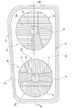
本発明の第1実施形態に係る車両用前照灯10は、例えば自動車等の車両の前端部分に取り付けられ、ハイビーム(走行ビーム)及びロービーム(すれ違いビーム)を選択的に切り替えて点消灯可能な4灯式の前照灯である。図1及び図2では、例として左側通行用車両の左前方に取り付けられる前照灯ユニット(ヘッドランプユニット)が車両用前照灯10として示されている。
Hereinafter, a vehicle headlamp according to an embodiment of the present invention will be described in detail with reference to the accompanying drawings.
A
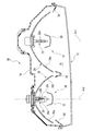
本実施形態に係る車両用前照灯10は、図1及び図2に示すように、前方が開口したランプボディ(灯体)14とその前方開口部に取り付けられた透光カバー12とで形成された灯室16内に、図示しないエイミング機構によって上下左右方向に傾動調整可能に支持された2つの灯具ユニット(すれ違いビームユニット18、走行ビームユニット20)が配置されている。
As shown in FIGS. 1 and 2, the
透光カバー12は、光透過性の素通しカバーであって、すれ違いビームユニット18及び走行ビームユニット20に配光制御機能が付与されている。
灯室16内における透光カバー12とすれ違いビームユニット18及び走行ビームユニット20との間には、両灯具ユニットの周縁部を覆うエクステンション34が設けられている。
The light-transmitting
An
すれ違いビームユニット18は、光源である放電バルブ22とリフレクタ24とシェード26とを備えている。
放電バルブ22は、メタルハライドバルブであって、すれ違いビームユニット18の光軸Ax1上に発光部22aが位置するようにしてリフレクタ24のバルブ取付孔に固定支持されている。
The passing
The
リフレクタ24は、光軸Ax1を中心軸とする略回転放物面上に複数の反射ステップが形成されてなる反射面24aを有している。反射面24aは、放電バルブ22からの光を前方へ偏向拡散反射させることにより、図5の(a)に示したすれ違いビーム用配光パターンPLを形成するようになっている。
シェード26は、放電バルブ22の前方側に設けられ、該放電バルブ22から前方へ向かう直射光をカットするようになっている。
The
The
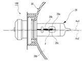
走行ビーム用ユニット20は、ダブルフィラメント光源である所謂H4タイプのハロゲンバルブ28とパラボラ型リフレクタ30とシェード32とを備えている。
H4タイプのハロゲンバルブ28は、走行ビーム用ユニット20の光軸Ax2方向にサブフィラメント(第1フィラメント)28aとメインフィラメント(第2フィラメント)28bとが略直列に配置されており、前方側に位置するサブフィラメント28aの側方近傍にはシェード28cが配置されている。
The traveling
In the H4
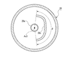
本実施形態のハロゲンバルブ28は、図3に示すように、サブフィラメント28aの一方(本実施形態においては車両左右方向における左方)の側方部位にシェード28cが位置すると共に、サブフィラメント28aの中心軸Ax3が他方(本実施形態においては車両左右方向における右方)の側方側へ約3度傾斜するようにパラボラ型リフレクタ30の取付孔に固定支持されている。また、メインフィラメント28bは、中心軸Ax3よりも僅かに左方に位置している。更に、ハロゲンバルブ28は、リフレクタ24における反射面24aの焦点Fがサブフィラメント28aとメインフィラメント28bとの間に位置するように配置される。
シェード28cは、図4に示すように、サブフィラメント28aの中心軸Ax3回りに約165度の遮蔽範囲角度θを有しているが、サブフィラメント28aの真横に位置している。
As shown in FIG. 3, in the
As shown in FIG. 4, the
本実施形態のパラボラ型リフレクタ30は、図1に示すように、光軸Ax2を中心軸とする略回転放物面上に複数の反射ステップが形成されてなる反射面を有している。パラボラ型リフレクタ30の反射面は、上下対称に斜めに引かれた境界線α,αにより、左右に二分割されており、車両左右方向における他方(本実施形態においては車両左右方向における右方)の側方側半分に設けられた第1反射面30aと、一方(本実施形態においては車両左右方向における左方)の側方側半分に設けられた第2反射面30bとを有する。
As shown in FIG. 1, the
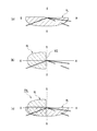
第1反射面30aは、少なくともサブフィラメント28aからの光を車両前方へ反射することによって、図5の(b)に示すように、自車線側の手前及び遠方に略半円形状の走行ビーム用配光パターンHLが得られるように各反射ステップが形成されている。また、第2反射面30bは、メインフィラメント28bからの光を車両前方へ真っ直ぐ反射して遠方を照射するように各反射ステップが形成されている。
そして、メインフィラメント28bからの光は、第1反射面30aで前方右向きに反射され、第2反射面30bで前方へ真っ直ぐ反射されることにより、図6の(c)に示す通常の走行ビーム用配光パターンPHを形成する。
The first reflecting
The light from the
シェード32は、ハロゲンバルブ28の前方側に設けられ、該ハロゲンバルブ28から前方へ向かう直射光をカットするようになっている。
更に、これらハロゲンバルブ28のサブフィラメント28a及びメインフィラメント28bや放電バルブ22は、図示しない点消灯回路により点灯制御される。
The
Further, the sub-filament 28a, the
尚、車両の右前方に取り付けられる車両用前照灯の図示しない走行ビーム用ユニットは、図2に示した走行ビーム用ユニット20とは左右対称に配置される。即ち、シェード28cがサブフィラメント28aの右方の側方部位に位置すると共に、サブフィラメント28aの中心軸Ax3が左方の側方側へ約3度傾斜するようにパラボラ型リフレクタ30に固定支持される。また、パラボラ型リフレクタ30の反射面も互いに左右対称に構成される。
Note that the traveling beam unit (not shown) of the vehicle headlamp mounted on the right front side of the vehicle is arranged symmetrically with the traveling
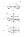
上述した本発明の第1実施形態に係る車両用前照灯10によれば、すれ違いビームユニット18の放電バルブ22を点灯すると、その光はリフレクタ24の反射面24aに当たって反射され、図5の(a)に示したすれ違いビーム用配光パターンPLを形成する。
According to the
次に、車両左側に取付けた走行ビーム用ユニット20におけるハロゲンバルブ28のサブフィラメント28aを点灯すると、その光はパラボラ型リフレクタ30の第1反射面30aに当たって反射され、図5の(b)に示したように、自車線側の手前及び遠方に略半円形状の走行ビーム用配光パターンHLを形成する。
Next, when the sub-filament 28a of the
そこで、車両左側のハロゲンバルブ28のサブフィラメント28aと放電バルブ22とを同時点灯すると、図5の(c)に示したように、対向車線側の遠方が照射されない走行ビーム用配光パターンPHLを形成することができる。
Therefore, when the sub-filament 28a and the
また、図示しない車両右側に取付けた走行ビーム用ユニットにおけるハロゲンバルブ28のサブフィラメント28aを点灯すると、その光はパラボラ型リフレクタ30の第1反射面30aに当たって反射され、対向車線側の手前及び遠方に略半円形状の走行ビーム用配光パターンHRを形成する(図6の(a)参照)。
Further, when the sub-filament 28a of the
そこで、車両右側のハロゲンバルブ28のサブフィラメント28aと放電バルブ22とを同時点灯すると、図6の(a)に示したように、自車線側の遠方が照射されない走行ビーム用配光パターンPHRを形成することができる。
更に、左右両側のハロゲンバルブ28のサブフィラメント28aと放電バルブ22とを同時点灯すると、図6の(b)に示したように、V−V線に沿った中央部が照射されない走行ビーム用配光パターンPHCを形成することができる。
Therefore, when the sub-filament 28a of the
Furthermore, when the sub-filament 28a and the
従って、上述したように、車両左右方向における一方の側方部位に配置したシェード28cにより不要部分を遮蔽した第1フィラメント28aからの光を他方の側方側半分に設けられた第1反射面30aにより車両前方へ反射させ、この反射光をすれ違いビームユニット18によるすれ違いビーム用配光パターンPL上に重ねることにより、複数の異なる走行ビーム用配光パターンPHL,PHR,PHCを形成することができる。
Therefore, as described above, the first reflecting
そこで、ハロゲンバルブ28のサブフィラメント28a及びメインフィラメント28bや放電バルブ22の点灯制御によって、複数の異なる配光パターンを切換えることができ、従来の車両用前照灯のようにシェードを移動させるアクチュエータ等の配光パターン調整機構が必要なくなって構造が簡単になる。
Therefore, a plurality of different light distribution patterns can be switched by lighting control of the sub-filament 28a and the
また、パラボラ型リフレクタ30の反射光により配光パターンを形成するので、適度なボケ具合のカットオフラインが形成されると共に該カットオフラインには色が出難くなるので、プロジェクタ型ヘッドランプに比べて光学系の設計・開発が容易になる。
従って、車両の走行状況等に応じて自動的に走行ビーム用配光パターンPHL,PHR,PHCを変化させることができると共に、軽量コンパクトで安価な車両用前照灯10を提供することができる。
Further, since the light distribution pattern is formed by the reflected light of the
Accordingly, the traveling beam light distribution patterns PHL, PHR, and PHC can be automatically changed according to the traveling state of the vehicle and the like, and the
更に、本第1実施形態のハロゲンバルブ28は、図3に示したように、サブフィラメント28aの一方の側方部位にシェード28cが位置すると共に、サブフィラメント28aの中心軸Ax3が他方の側方側へ約3度傾斜するようにパラボラ型リフレクタ30の取付孔に固定支持されている。そして、シェード28cにより遮蔽したサブフィラメント28aからの光を第1反射面30aにより車両前方へ反射させる構成とされている。
Further, in the
そこで、第1フィラメント30aの中心軸Ax3回りの遮蔽範囲角度θが約165度であるシェード28cを用いたまま、H−H線(水平線)に対して上下方向に延びる略垂直なカットオフラインVCLを備えた配光パターンを形成することができる。
従って、既存のH4タイプのハロゲンバルブ28を用いながら、略垂直なカットオフラインVCLを備えた良好な走行ビーム用配光パターンPHL,PHR,PHCを形成することができる。
Therefore, a substantially vertical cut-off line VCL extending in the vertical direction with respect to the HH line (horizontal line) is used while using the
Therefore, it is possible to form good traveling beam light distribution patterns PHL, PHR, and PHC having a substantially vertical cut-off line VCL while using the existing H4
図7は、本発明の第2実施形態に係る車両用前照灯100を説明する要部拡大側面図である。尚、本第2実施形態の車両用前照灯100は、走行ビームユニット20のパラボラ型リフレクタ30に対するハロゲンバルブ28の取付位置を変更したものであり、他の構成部材は上記第1実施形態の車両用前照灯10における構成部材と略同様であるので、同符号を付して詳細な説明を省略する。
FIG. 7 is an enlarged side view of a main part for explaining the
本第2実施形態に係るハロゲンバルブ28は、図7に示すように、サブフィラメント28aの一方(本実施形態においては車両左右方向における左方)の側方部位にシェード28cが位置すると共に、サブフィラメント28aの車両後方側の下端がパラボラ型リフレクタ30の焦点Fに配置されるようにパラボラ型リフレクタ30の取付孔に固定支持されている。そして、サブフィラメント28aの中心軸Ax3は、走行ビーム用ユニット20の光軸Ax2よりも僅かに上方に位置している。
As shown in FIG. 7, the
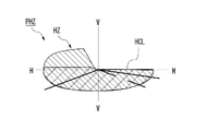
本第2実施形態に係る第1反射面30aは、少なくともサブフィラメント28aからの光を車両前方へ反射することによって、自車線側の手前及び遠方と対向車線側の手前とに走行ビーム用配光パターンHZが得られるように各反射ステップが形成されている(図8参照)。
そして、シェード28cにより遮蔽したサブフィラメント28aからの光は、パラボラ型リフレクタ30の第1反射面30aにより車両前方へ偏向拡散反射させられると、対向車線側に略水平なカットオフラインHCLを備えた走行ビーム用配光パターンHzを形成する。
The first reflecting
Then, when the light from the
上述した本発明の第2実施形態に係る車両用前照灯100によれば、車両左側のハロゲンバルブ28のサブフィラメント28aと放電バルブ22とを同時点灯すると、図8に示したように、対向車線側に略水平なカットオフラインHCLを備えて該対向車線側の遠方が照射されない走行ビーム用配光パターンPHZを形成することができる。この走行ビーム用配光パターンPHZは、図5の(c)に示した第1実施形態の車両用前照灯10に係る走行ビーム用配光パターンPHLに比べて、対向車線側の手前の光度を高めることができ、均一で視認性の良好な配光パターンを得ることができる。
According to the
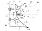
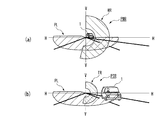
図9は、本発明の第3実施形態に係る車両用前照灯200を説明する要部水平断面図である。尚、本第3実施形態の車両用前照灯200は、走行ビームユニットの構成を変更したものであり、他の構成部材は上記第1実施形態の車両用前照灯10における構成部材と略同様であるので、同符号を付して詳細な説明を省略する。
FIG. 9 is a horizontal cross-sectional view of a main part for explaining a
本第3実施形態に係る走行ビームユニット220は、パラボラ型リフレクタ230がハロゲンバルブ28に対し車両前後方向に移動可能に配設されており、エイミング機構210のベース部材212を介してランプボディ14に取り付けられている。
そして、このエイミング機構210を介してパラボラ型リフレクタ230の取り付け角度を変化させることで、走行ビームユニット220から出射する光の光軸Ax2を調整可能としている。
In the
Then, by changing the mounting angle of the
本第3実施形態のパラボラ型リフレクタ230は、ベース部材212に固定されたアクチュエータ215,215によって、それぞれ車両前後方向に駆動される。そこで、パラボラ型リフレクタ230の反射面は、灯具光軸Ax2に沿って前後方向(図9中、左右方向)に移動される。
更に、パラボラ型リフレクタ230の反射面は、斜めに引かれた上部境界線と鉛直方向に引かれた下部境界線とにより、左右に二分割されており、車両右方の側方側半分に設けられた第1反射面230aと、車両左方の側方側半分に設けられた第2反射面230bとを有する。
The
Further, the reflecting surface of the
パラボラ型リフレクタ230の第1反射面230aは、光軸Ax2を中心軸とする回転放物形状に形成されている。そこで、シェード28cにより遮蔽したサブフィラメント28aからの光は、第1反射面230aにより車両前方へ反射させられると、車両前方のH−H線(水平線)とV−V線(垂直線)の交点付近へ向かう照射光が抜けて中央の遠方照射範囲がカットされた略半円形状の走行ビーム用配光パターンWRを形成する(図10の(a)参照)。
The first reflecting
上述した本発明の第3実施形態に係る車両用前照灯200によれば、パラボラ型リフレクタ230を車両前方に移動させて第1反射面230aの焦点Fよりも後方にサブフィラメント28aを配置した状態で車両左側のハロゲンバルブ28のサブフィラメント28aと放電バルブ22とを同時点灯すると、図10の(a)に示すように、投影される走行ビーム用配光パターンWRが拡大され、カットする遠方照射範囲が大きく、対向車線側の遠方が照射されない走行ビーム用配光パターンPWRを形成することができる。
According to the
また、パラボラ型リフレクタ230を車両後方に移動させて第1反射面230aの焦点Fよりも前方にサブフィラメント28aを配置した状態で車両左側のハロゲンバルブ28のサブフィラメント28aと放電バルブ22とを同時点灯すると、図10の(b)に示すように、投影される走行ビーム用配光パターンTRが縮小された走行ビーム用配光パターンPTRを形成することができる。
In addition, the
従って、本第3実施形態に係る車両用前照灯200は、パラボラ型リフレクタ230をハロゲンバルブ28に対して車両前後方向に移動させることで、カットする遠方照射範囲の大きさと共に走行ビーム用配光パターンWR(TR)の大きさ及び光度を変えることができる。
そこで、対向車1が遠い時には走行ビーム用配光パターンPWRを照射し、対向車1が近い時には走行ビーム用配光パターンPTRを照射することで、対向車1へのグレアを防止しながら最大限の照射範囲を確保することができ、良好な視認性を得ることができる。
Therefore, in the
Therefore, the traveling beam light distribution pattern PWR is irradiated when the oncoming vehicle 1 is far away, and the traveling beam light distribution pattern PTR is irradiated when the oncoming vehicle 1 is near, thereby preventing glare to the oncoming vehicle 1 to the maximum. Can be ensured, and good visibility can be obtained.
尚、本発明の車両用前照灯に係るすれ違いビームユニット、走行ビーム用ユニット、ダブルフィラメント光源及びパラボラ型リフレクタ等の構成は、上記各実施形態の構成に限定されるものではなく、本発明の趣旨に基づいて種々の形態を採りうることは云うまでもない。
例えば、すれ違いビームユニットにおける光源は、放電バルブ22に限らず、ハロゲンバルブや発光ダイオード等の半導体発光素子を用いることもできる。
Note that the configurations of the passing beam unit, the traveling beam unit, the double filament light source, the parabolic reflector, and the like according to the vehicle headlamp of the present invention are not limited to the configurations of the above-described embodiments. It goes without saying that various forms can be adopted based on the purpose.
For example, the light source in the passing beam unit is not limited to the
また、車両の左右前方にそれぞれ取り付けられる各前照灯ユニットにおけるダブルフィラメント光源のシェード配置とパラボラ型リフレクタの第1反射面との組み合わせは、互いのシェードが車両側方側に対称に位置する上記実施形態の組み合わせに限定されるものではなく、互いのシェードが車両中心側に対称に位置するなど種々の組み合わせが可能である。 Further, the combination of the shade arrangement of the double filament light source and the first reflecting surface of the parabolic reflector in each headlight unit attached to each of the left and right front parts of the vehicle is such that the shades are symmetrically located on the side of the vehicle. The present invention is not limited to the combination of the embodiments, and various combinations such as mutual shades being symmetrically positioned on the vehicle center side are possible.
10…車両用前照灯
12…透光カバー
14…ランプボディ
16…灯室
18…すれ違いビームユニット
20…走行ビームユニット
28…ハロゲンバルブ(ダブルフィラメント光源)
28a…サブフィラメント(第1フィラメント)
28b…サブフィラメント(第2フィラメント)
28c…シェード
30…パラボラ型リフレクタ
30a…第1反射面
30b…第2反射面
DESCRIPTION OF
28a ... Subfilament (first filament)
28b ... Subfilament (second filament)
28c ...
Claims (4)
前記走行ビームユニットは、
車両左右方向における一方の側方部位にシェードを配置した第1フィラメントと第2フィラメントとを有するダブルフィラメント光源と、
車両左右方向における他方の側方側半分に設けられて少なくとも前記第1フィラメントからの光を車両前方へ反射する第1反射面と、車両左右方向における一方の側方側半分に設けられて前記第2フィラメントからの光を車両前方へ反射する第2反射面とを有するパラボラ型リフレクタと、を備え、
前記ダブルフィラメント光源及び前記すれ違いビームユニットの点灯制御によって、複数の異なる配光パターンを切換え可能に構成したことを特徴とする車両用前照灯。 A vehicle headlamp including a low beam unit that irradiates a light distribution pattern for low beam and a traveling beam unit that irradiates a light distribution pattern for low beam,
The traveling beam unit includes:
A double filament light source having a first filament and a second filament in which a shade is disposed at one side portion in the vehicle left-right direction;
A first reflecting surface provided on the other side half of the vehicle in the left-right direction and reflecting at least light from the first filament forward of the vehicle; and provided on one side half of the vehicle in the left-right direction. A parabolic reflector having a second reflecting surface for reflecting light from the two filaments toward the front of the vehicle,
A vehicle headlamp characterized in that a plurality of different light distribution patterns can be switched by lighting control of the double filament light source and the passing beam unit.
Priority Applications (1)
| Application Number | Priority Date | Filing Date | Title |
|---|---|---|---|
| JP2009185176A JP5478144B2 (en) | 2009-08-07 | 2009-08-07 | Vehicle headlamp |
Applications Claiming Priority (1)
| Application Number | Priority Date | Filing Date | Title |
|---|---|---|---|
| JP2009185176A JP5478144B2 (en) | 2009-08-07 | 2009-08-07 | Vehicle headlamp |
Publications (2)
| Publication Number | Publication Date |
|---|---|
| JP2011040231A JP2011040231A (en) | 2011-02-24 |
| JP5478144B2 true JP5478144B2 (en) | 2014-04-23 |
Family
ID=43767799
Family Applications (1)
| Application Number | Title | Priority Date | Filing Date |
|---|---|---|---|
| JP2009185176A Expired - Fee Related JP5478144B2 (en) | 2009-08-07 | 2009-08-07 | Vehicle headlamp |
Country Status (1)
| Country | Link |
|---|---|
| JP (1) | JP5478144B2 (en) |
Families Citing this family (5)
| Publication number | Priority date | Publication date | Assignee | Title |
|---|---|---|---|---|
| JP6567245B2 (en) * | 2012-12-27 | 2019-08-28 | 市光工業株式会社 | Vehicle headlamp |
| CN116379373B (en) * | 2017-05-17 | 2025-08-01 | 株式会社小糸制作所 | Optical unit |
| CN110701496A (en) * | 2019-09-17 | 2020-01-17 | 福建明旺能源科技有限公司 | LED lamp |
| CN110864265B (en) * | 2019-11-22 | 2022-06-21 | 芜湖安瑞光电有限公司 | Steering lamp reflector structure |
| KR102778358B1 (en) * | 2020-03-25 | 2025-03-10 | 에스엘 주식회사 | Lamp for vehicle |
Family Cites Families (7)
| Publication number | Priority date | Publication date | Assignee | Title |
|---|---|---|---|---|
| JPS6044302U (en) * | 1983-09-05 | 1985-03-28 | スタンレー電気株式会社 | vehicle headlights |
| JPH0531764Y2 (en) * | 1987-07-21 | 1993-08-16 | ||
| JPH0218203U (en) * | 1988-07-20 | 1990-02-06 | ||
| JP2598577B2 (en) * | 1991-05-17 | 1997-04-09 | 株式会社小糸製作所 | Automotive headlamp |
| JP3394610B2 (en) * | 1994-11-18 | 2003-04-07 | 株式会社小糸製作所 | Automotive headlamp |
| JP4654951B2 (en) * | 2006-03-16 | 2011-03-23 | 市光工業株式会社 | Vehicle lighting |
| JP4714088B2 (en) * | 2006-06-16 | 2011-06-29 | 株式会社小糸製作所 | Vehicle headlamp |
-
2009
- 2009-08-07 JP JP2009185176A patent/JP5478144B2/en not_active Expired - Fee Related
Also Published As
| Publication number | Publication date |
|---|---|
| JP2011040231A (en) | 2011-02-24 |
Similar Documents
| Publication | Publication Date | Title |
|---|---|---|
| KR101047371B1 (en) | Headlights for vehicles | |
| JP3898462B2 (en) | Vehicle headlamp | |
| JP4392786B2 (en) | Vehicle headlamp | |
| JP4061233B2 (en) | Vehicle headlamp | |
| JP2010000957A (en) | Headlight device for vehicle | |
| JP2017191748A (en) | Vehicular lighting fixture and vehicle including the same | |
| JP2012038609A (en) | Vehicular headlight | |
| JP4343003B2 (en) | Vehicle headlamp | |
| JP4339213B2 (en) | Vehicle headlamp | |
| JP5478144B2 (en) | Vehicle headlamp | |
| JP4257675B2 (en) | Vehicle headlamp | |
| JP4261452B2 (en) | Vehicle headlamp | |
| JP5539796B2 (en) | Vehicle headlight system | |
| JP2010235108A (en) | Headlight device for vehicle | |
| JP5843332B2 (en) | Vehicle lamp | |
| JP6142540B2 (en) | Vehicle headlamp | |
| JP5513915B2 (en) | Vehicle headlamp | |
| JP2010015837A (en) | Headlight device for vehicle | |
| JP3989734B2 (en) | Vehicle headlamp | |
| JP2006100132A (en) | Headlamp for vehicle | |
| JP5610949B2 (en) | Vehicle headlamp | |
| JP2006196410A (en) | Headlamp for vehicle | |
| JP2003168307A (en) | Vehicular headlamp | |
| JP2006040785A (en) | Vehicular headlamp | |
| JP4536474B2 (en) | Vehicle headlamp |
Legal Events
| Date | Code | Title | Description |
|---|---|---|---|
| A621 | Written request for application examination |
Free format text: JAPANESE INTERMEDIATE CODE: A621 Effective date: 20120711 |
|
| RD02 | Notification of acceptance of power of attorney |
Free format text: JAPANESE INTERMEDIATE CODE: A7422 Effective date: 20120730 |
|
| A977 | Report on retrieval |
Free format text: JAPANESE INTERMEDIATE CODE: A971007 Effective date: 20130724 |
|
| A131 | Notification of reasons for refusal |
Free format text: JAPANESE INTERMEDIATE CODE: A131 Effective date: 20130730 |
|
| A521 | Written amendment |
Free format text: JAPANESE INTERMEDIATE CODE: A523 Effective date: 20130808 |
|
| TRDD | Decision of grant or rejection written | ||
| A01 | Written decision to grant a patent or to grant a registration (utility model) |
Free format text: JAPANESE INTERMEDIATE CODE: A01 Effective date: 20140204 |
|
| A61 | First payment of annual fees (during grant procedure) |
Free format text: JAPANESE INTERMEDIATE CODE: A61 Effective date: 20140210 |
|
| R150 | Certificate of patent or registration of utility model |
Ref document number: 5478144 Country of ref document: JP Free format text: JAPANESE INTERMEDIATE CODE: R150 |
|
| LAPS | Cancellation because of no payment of annual fees |