JP5476898B2 - Vehicle sliding door structure - Google Patents
Vehicle sliding door structure Download PDFInfo
- Publication number
- JP5476898B2 JP5476898B2 JP2009226604A JP2009226604A JP5476898B2 JP 5476898 B2 JP5476898 B2 JP 5476898B2 JP 2009226604 A JP2009226604 A JP 2009226604A JP 2009226604 A JP2009226604 A JP 2009226604A JP 5476898 B2 JP5476898 B2 JP 5476898B2
- Authority
- JP
- Japan
- Prior art keywords
- flange portion
- sliding door
- vehicle
- width direction
- vehicle width
- Prior art date
- Legal status (The legal status is an assumption and is not a legal conclusion. Google has not performed a legal analysis and makes no representation as to the accuracy of the status listed.)
- Expired - Fee Related
Links
Images


Landscapes
- Power-Operated Mechanisms For Wings (AREA)
Description
本発明は、車両のスライドドア構造に関するものである。 The present invention relates to a sliding door structure for a vehicle.
車両の中には、例えば1ボックスカーにおいて多く見られるように、後側の側方開口部を前後方向にスライド動されるスライドドアによって開閉するものがある。このようなスライドドアを電動式としてモータの駆動力によって開閉する場合に、スライドドアを閉じるときにその前縁部と車体(ピラー部材)との間で挟み込みを生じてしまうおそれがある。この挟み込み検知のために、特許文献1に示すように、スライドドアの前縁部に形成される上下方向に伸びるフランジ部に対して、上下方向に伸びるセンサ部材を取付けることが開示されている。そして、このセンサ部材を、上記フランジ部に取付けられるシール部材内に配設した構造、つまりシール部材とセンサ部材とを一体化構造とすることも開示されている。
Some vehicles open and close a rear side opening by a sliding door that is slid in the front-rear direction, as is often seen, for example, in one box car. When such a slide door is electrically operated and is opened and closed by a driving force of a motor, there is a risk that the front door and the vehicle body (pillar member) may be pinched when the slide door is closed. For this pinching detection, as shown in
ところで、スライドドアにおいては、その前縁部に形成するフランジ部を、デザイン等の観点から連続して形成することが難しい場合が生じる。例えば、スライドドアのアウタパネルを、ベルトライン部において車幅方向外方側に膨出させた場合に、この部分での曲がりが大きくなって、フランジ部を連続して形成することが難しなる。より具体的には、ベルトライン部よりも上側部分の上フランジ部と、ベルトライン部よりも下側部分の下フランジ部とを形成することが可能であっても、この上下のフランジ部との間にフランジ部を形成することが難しくなる。 By the way, in a sliding door, it may be difficult to form continuously the flange part formed in the front edge part from viewpoints, such as a design. For example, when the outer panel of the slide door bulges outward in the vehicle width direction at the belt line portion, the bending at this portion becomes large and it is difficult to continuously form the flange portion. More specifically, even if it is possible to form the upper flange portion above the belt line portion and the lower flange portion below the belt line portion, It becomes difficult to form a flange portion therebetween.
上述のように、フランジ部が上下方向に連続して形成されていない場合に、これに取付けられるセンサ部材は、上下方向中間部分(ベルトライン部)で支承されないことになって、挟み込み検知用のセンサ部材の取付強度確保等の点でなんらかの対策が望まれることになる。 As described above, when the flange portion is not continuously formed in the vertical direction, the sensor member attached to the flange portion is not supported by the intermediate portion in the vertical direction (belt line portion). Some measures are desired in terms of securing the mounting strength of the sensor member.
本発明は以上のような事情を勘案してなされたもので、その目的は、スライドドアの上下方向中間部にフランジ部を形成することが難しい場合であっても、挟み込み検知用のセンサ部材のスライドドアへの取付けをしっかりを行えるようにした車両のスライドドア構造を提供することにある。 The present invention has been made in view of the above circumstances, and its purpose is to provide a sensor member for detecting pinching even when it is difficult to form a flange portion in the middle portion in the vertical direction of the sliding door. An object of the present invention is to provide a sliding door structure for a vehicle that can be securely attached to the sliding door.
前記目的を達成するため、本発明にあっては次のような第1の解決手法を採択してある。すなわち、特許請求の範囲における請求項1に記載のように、
車両の側方開口部が前後方向にスライド動される電動式のスライドドアによって開閉され、該スライドドアの前縁部に形成された上下方向に伸びるフランジ部に挟み込み検知用のセンサ部材が上下方向に伸ばして取付けられた車両のスライドドア構造において、
前記フランジ部が、上フランジ部と、該上フランジ部と上下方向に離間された下フランジ部と、スライドドアに取付けられたブラケットに形成されて該上フランジ部と該下フランジ部とを接続する接続フランジ部とによって構成され、
前記センサ部材が、前記上フランジ部から前記接続フランジ部を経由して前記下フランジ部に渡って取付けられ、
スライドドアを前方から見たときに、前記接続フランジ部の車幅方向外方側において、スライドドアのアウタパネルとインナパネルとの接合部間の隙間が目視可能に露出され、
前記接合部間の隙間を覆う遮蔽部材が設けられている、
ようにしてある。上記解決手法によれば、スライドドアに取付けられるブラケットに形成された接続フランジ部を利用して、スライドドアの前縁部に上下方向に連続したフランジ部を形成することができる。これにより、挟み込み検知用のセンサ部材を、上下方向の長い範囲に渡ってスライドドアにしっかりと取付けることができ、挟み込みを精度よく検知する等の上で好ましいものとなる。以上に加えて、外観上の見栄えをよくする上で好ましいものとなる。
In order to achieve the above object, the following first solution is adopted in the present invention. That is, as described in
The side opening of the vehicle is opened and closed by an electric slide door that is slid in the front-rear direction, and the sensor member for detecting pinching is sandwiched by a vertically extending flange formed on the front edge of the slide door. In the vehicle sliding door structure attached to
The flange portion is formed on an upper flange portion, a lower flange portion that is vertically separated from the upper flange portion, and a bracket that is attached to a slide door, and connects the upper flange portion and the lower flange portion. The connection flange part
The sensor member via the connecting flange portions from the upper flange portion mounted et al is over the lower flange portion,
When the sliding door is viewed from the front, on the outer side in the vehicle width direction of the connection flange portion, a gap between the joint portions of the outer panel and the inner panel of the sliding door is exposed so as to be visible.
A shielding member that covers the gap between the joints is provided,
It is like that. According to the above solution, a flange portion that is continuous in the vertical direction can be formed on the front edge portion of the slide door using the connection flange portion formed on the bracket attached to the slide door. Thereby, the sensor member for pinching detection can be firmly attached to the slide door over a long range in the vertical direction, which is preferable for detecting pinching with high accuracy. In addition to the above, it is preferable for improving the appearance.
上記解決手法を前提とした好ましい態様は、特許請求の範囲における請求項2以下に記載のとおりである。すなわち、
前記接続フランジ部が、スライドドアンのベルトライン部の高さ位置に設けられ、
スライドドアに、前記ベルトライン部において車幅方向外側に膨出する膨出部が形成されている、
ようにしてある(請求項2対応)。この場合、スライドドアのデザイン上の要求からベルトライン部に膨出部を形成した場合であっても、センサ部材をベルトライン部においてもしっかりとスライドドアに取付けておくことができる。
A preferred mode based on the above solution is as described in
The connecting flange portion is provided at a height position of the belt line portion of the sliding door;
The sliding door is formed with a bulging portion that bulges outward in the vehicle width direction at the belt line portion.
(Corresponding to claim 2). In this case, the sensor member can be firmly attached to the sliding door even in the belt line portion even when the bulging portion is formed in the belt line portion due to the design requirements of the sliding door.
前記センサ部材が、上下方向に伸びるシール部材内に配設され、
前記遮蔽部材が、前記シール部材に一体的に設けられたリップによって構成されている、
ようにしてある(請求項3対応)。この場合、シール部材をフランジ部に取付けることによって、遮蔽部材を接合部間の隙間を遮蔽する所定位置に配設することができる。また、シール部材に形成されるリップは風きり音対策の上でも好ましいものとなる。
The sensor member is disposed in a seal member extending in a vertical direction;
The shielding member is constituted by a lip provided integrally with the seal member.
(Corresponding to claim 3 ). In this case, by attaching the seal member to the flange portion, the shielding member can be disposed at a predetermined position that shields the gap between the joint portions. Further, the lip formed on the seal member is preferable from the viewpoint of wind noise.
前記ブラケットに、前記接続フランジ部に対して車幅方向内方側に引っ込むように形成された段部を介して、上下一対の当接部が形成され、
前記上当接部が、前記上フランジ部の下端部に車幅方向内方側から当接され、
前記下当接部が、前記下フランジ部の上端部に対して車幅方向内方側から当接されている、
ようにしてある(請求項4対応)。この場合、上当接部を上フランジ部の下端部に対して車幅方向内方側から当接させると共に、下当接部を下フランジ部の上端部に対して車幅方向内方側から当接させることによって、接続フランジ部を上下のフランジ部に対してきちんと位置決めされた状態で整合させることができる(接続フランジ部の位置決め作業の容易化)。
A pair of upper and lower contact portions is formed on the bracket via a step portion formed so as to be retracted inward in the vehicle width direction with respect to the connection flange portion.
The upper contact portion is contacted to the lower end portion of the upper flange portion from the inner side in the vehicle width direction,
The lower contact portion is in contact with the upper end portion of the lower flange portion from the inner side in the vehicle width direction,
(Corresponding to claim 4 ). In this case, the upper contact portion is brought into contact with the lower end portion of the upper flange portion from the inner side in the vehicle width direction, and the lower contact portion is made contact with the upper end portion of the lower flange portion from the inner side in the vehicle width direction. By making contact, the connection flange portion can be aligned in a properly positioned state with respect to the upper and lower flange portions (ease of positioning of the connection flange portion).
前記接続フランジ部のうち前記上フランジ部または前記下フランジ部との少なくとも一方に対する接続部分に対して、樹脂コーティングが施されている、ようにしてある(請求項5対応)。この場合、走行中に振動を受けたときでも、接続フランジ部が上フランジ部または下フランジ部に当接することによる摩耗や異音の発生を防止できる。 A resin coating is applied to a connection portion of at least one of the connection flange portion and the upper flange portion or the lower flange portion (corresponding to claim 5 ). In this case, even when receiving vibration during traveling, it is possible to prevent wear and noise from occurring due to the connection flange portion coming into contact with the upper flange portion or the lower flange portion.
本発明によれば、スライドドアそのものにフランジ部を上下方向に連続して形成できない場合でも、ブラケットに形成された接続フランジ部を利用して、挟み込み検知用のセンサ部材をスライドドアにしっかりと取付けることができる。 According to the present invention, even when the flange portion cannot be continuously formed in the vertical direction on the slide door itself, the pinching detection sensor member is firmly attached to the slide door using the connection flange portion formed on the bracket. be able to.
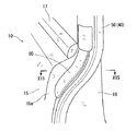
図1において、車両Vは、その前方から後方に向けて、Aピラー1,Bピラー2,Cピラー3,Dピラー4を有する。Aピラー1とBピラー2との間に形成される前側方開口部5が、前サイドドア6によって開閉される。前サイドドア6は、その前端部に設けたヒンジを中心として、後開きとされている。また、Bピラー2とCピラー3との間に形成される後側方開口部7が、前後方向にスライドされるスライドドア10によって開閉される。スライドドア10は、電動式(モータ駆動式)とされて、運転席付近において車室内に設けたドアスイッチ(図示を略す)を操作することによって開閉される。
In FIG. 1, a vehicle V has an
スライドドア10は、図3,図6,図8、図11に特に明瞭に示すように、そのサイドウインドガラス11の下縁部付近となるベルトライン部12の高さ位置において、車幅方向外側に膨出する膨出部13が形成されている。すなわち、スライドドア10は、アウタパネル15とインナパネル16とによって構成されて、アウタパネル15が、ベルトライン部12の高さ位置でもって車幅方向外側に膨出されている。この膨出部13の形成によって、スライドドア10(のアウタパネル15)のデザイン性が向上されている。なお、膨出部13の形成によって形成されるアウタパネル15の段部上には、ベルトライン12に沿ってモール17が取付けられている。
As shown clearly in FIGS. 3, 6, 8, and 11, the sliding
スライドドア10の前縁部には、図6〜図9に示すように、上フランジ部21と下フランジ部22とが形成されている。上フランジ部21は、ベルトライン部12よりも若干上方位置から上方に向けて伸びている。また、下フランジ部22は、ベルトライン部12よりも若干下方位置から、下方に向けて伸びている。そして、上下のフランジ部21と22との間には、スライドドア10そのものにはフランジ部が形成されていない構造となっている。すなわち、膨出部13の形成によって、ベルトライン部12およびその付近の高さ位置では、アウタパネル15が車幅方向外側へ大きく曲げられているため、フランジ部を形成することが難しいものとなっている。
As shown in FIGS. 6 to 9, an
上下のフランジ部21,22の形成は、次のようにして行われている。まず、アウタパネル15の前端部が、若干車幅方向内方側に向けて曲げられることにより、上下方向に伸びる前縦面部15aが形成される。この前縦面部15aの車幅方向内端部から前方へ伸ばして、上下のフランジ部21,22が形成されている。各フランジ部21,22は、車体後方側へ略180度折り返されている。そして、インナパネル16の前端部が、特に図4に示すように、各フランジ部21,22の上記折り返し部に挟みまれた状態(ヘミング処理)でアウタパネル15に接合されている(接合部にはシーラが介在される)。
The upper and
一方、上下のフランジ部21,22が位置しない部分では、アウタパネル15は、前縦面部15aは有するが、この前縦面部15aから伸びるフランジ部を有しないものとなっている。すなわち、特に図5に示すように、前縦面部15aの車幅方向内端部から後方へ略90度折り曲げられた側方縦面部15bとされている。そして、インナパネル16の前端部が、側方縦面部15bよりも車幅方向外方側において、前縦面部15aの後面に当接状態とされて、この当接部分においてシーラによってアウタパネル15に接合されている。
On the other hand, in the portion where the upper and
スライドドア10には、ベルトライン部12の高さ付近において、ブラケット30がボルト35によって固定されている(図8、図9,図11参照)。このブラケット30は、例えば鉄板等の金属板を加工することにより形成されて、接続フランジ部31を有する。この接続フランジ部31は、ブラケット30をスライドドア10の所定位置に固定したときに、上下のフランジ部21,22に対して滑らかに連なるように整合される。すなわち、接続フランジ部31の上端が上フランジ部21の下端に連なり、接続フランジ部31の下端が下フランジ部22の上端に連なっている。このように、上下のフランジ部21,22と接続フランジ部31とによって、スライドドア10の前縁部には、上下方向に長くかつ連続したフランジ部が構成される。
A
ブラケット30は、接続フランジ部31の上下の端部において、上下一対の当接部32,33を有する。上当接部32は、段部32aによって接続フランジ部31に連なると共に、接続フランジ部31よりもわずかに車幅方向内方側に位置されて、接続フランジ部31よりも上方に伸びている。同様に、下当接部33は、段部33aによって接続フランジ部31に連なると共に、接続フランジ部31よりもわずかに車幅方向内方側に位置されて、接続フランジ部31よりも下方に伸びている。
The
上当接部32を上フランジ部21の車幅方向内方側に当接させた状態で、接続フランジ部31の上端が、上フランジ部21の下端に連なる整合状態とされる(位置決め)。同様に、下当接部33を下フランジ部22の車幅方向内方側に当接させた状態で、接続フランジ部31の下端が、下フランジ部22の下端に連なる整合状態とされる(位置決め)。このように、上下の当接部32,33を上下のフランジ部21,22に当接させた状態で、ブラケット30を車体に固定することにより、上下のフランジ部21,22に対して接続フランジ部31が連なる整合状態が容易に得られることになる。
In a state where the
接続フランジ部31のうち少なくとも上下の各端部(特に端面)、および上下の当接部32,33(特に車幅方向外側面)には、樹脂コーティングが施されている。これにより、走行中の振動を受けても、樹脂コーティングの緩衝機能によって、接続フランジ部31や上下の当接部32,33が上下のフランジ部21,22に当接した際の摩耗や異音の発生が防止される。勿論、樹脂コーティングすることによって、防錆機能も得られることになる。なおブラケット30を金属ではなく合成樹脂によって形成した場合は、上記のような樹脂コーティングを別途行う必要のないものとなる。
At least the upper and lower end portions (particularly end surfaces) and the upper and
前記上下のフランジ部21,22と接続フランジ部31とによって構成されるフランジ部に対して、挟み込み検知用のセンサ部材40が取付けられる(図3,図11参照)。センサ部材40は、シール部材に一体化されている。すなわち、弾性部材からなるシール部材50の前端部の内部に、センサ部材40が埋め込まれた構造とされている。勿論、シール部材50は上下方向に長くされ、同様にセンサ部材40も上下方向に長く伸びている。
A
センサ部材40つまりシール部材50は、上フランジ部21から接続フランジ部31を経由して下フランジ部22に渡って取付けられている。このように、シール部材50(センサ部材40)は、上下方向においてとぎれることなくフランジ部に取付けられることになって、その取付けが適正位置においてしっかりと行われることになり、挟み込み検知を常に適切な位置で行うことができる。勿論、センサ部材40は、スライドドア10を閉じるときに、スライドドア10とBピラー2との間での挟み込みを検知するものとなっている。
The
図12,図13に示すように、シール部材50には、リップ部51が一体成形されている。このリップ部51は、ベルトライン部12よりも上方位置で、閉位置にある前サイドドア6の後縁部に当接される(シール確保および風きり音低減)。これに対して、ベルトライン部12付近では、図13に示すように、リップ部51が存在しないものとなっている。
As shown in FIGS. 12 and 13, a
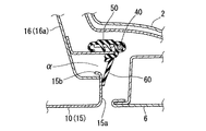
図14〜図17は、本発明の第2の実施形態を示すもので、膨出部13を形成することによって生じる外観上の見栄え悪化を防止するものとなっている。すなわち、前記実施形態においては、例えば図3,図11に示すように、スライドドア10をその前方から見たとき、ベルトライン部12付近において、接続フランジ部31(シール部材50)の車幅方向外側には、アウタパネル15とインナパネル16との接合部間の隙間αが目視可能となっている。つまり、膨出部13の形成によって、接続フランジ部31の車幅方向外側からは、隙間αを通して、インナパネル16のうち車幅方向に伸びる前縦面16aやアウタパネル15の側方縦面部15bがそのまま目視可能となっている。このインナパネル16の前縦面部16aは、アウタパネル15の前縦面部15aよりも後方に位置されて、前縦面部15aに対して滑らかに連なっていないことから、外観上の見栄えの上では好ましくないものとなる。
14 to 17 show a second embodiment of the present invention, which prevents appearance deterioration caused by forming the bulging
図14〜図17に示す第2実施形態では、遮蔽部材60を用いて、上記隙間αを遮蔽する(塞ぐ)ようにしてある。この遮蔽部材60は、図14に示すように、前記リップ部51下端に連続してベルトライン部12付近にのみ設けられて、隙間αを前方から遮蔽している。遮蔽部材60は、弾性部材によって、シール部材50とは別部材として形成されて、シール部材50に対してあらかじめ接着剤や熱融着等によって一体化されている。すなわち、あらかじめ遮蔽部材60が一体化された状態のシール部材50が、フランジ部に取付けられることになる。なお、この遮蔽部材60は、シール部材50と一体成形することもできる。
In the second embodiment shown in FIGS. 14 to 17, the gap α is shielded (closed) using the shielding
以上実施形態について説明したが、本発明は、実施形態に限定されるものではなく、特許請求の範囲の記載された範囲において適宜の変更が可能である。勿論、本発明の目的は、明記されたものに限らず、実質的に好ましいあるいは利点として表現されたものを提供することをも暗黙的に含むものである。 Although the embodiments have been described above, the present invention is not limited to the embodiments, and appropriate modifications can be made within the scope of the claims. Of course, the object of the present invention is not limited to what is explicitly stated, but also implicitly includes providing what is substantially preferred or expressed as an advantage.
本発明は、自動車等の車両における安全確保の技術として好ましいものとなる。 The present invention is preferable as a technology for ensuring safety in vehicles such as automobiles.
V:車両
α:隙間
7:後側方開口部
10:スライドドア
12:ベルトライン部
13:膨出部
15:アウタパネル
15a:前縦面部
15b:側方縦面部
16:インナパネル
16a:前縦面部
21:上フランジ部
22:下フランジ部
30:ブラケット
31:接続フランジ部
32:上当接部
32a:段部
33:下当接部
33a:段部
40:センサ部材
50:シール部材
51:リップ部
60:遮蔽部材
V: vehicle α: gap 7: rear side opening 10: sliding door 12: belt line portion 13: bulging portion 15:
Claims (5)
前記フランジ部が、上フランジ部と、該上フランジ部と上下方向に離間された下フランジ部と、スライドドアに取付けられたブラケットに形成されて該上フランジ部と該下フランジ部とを接続する接続フランジ部とによって構成され、
前記センサ部材が、前記上フランジ部から前記接続フランジ部を経由して前記下フランジ部に渡って取付けられ、
スライドドアを前方から見たときに、前記接続フランジ部の車幅方向外方側において、スライドドアのアウタパネルとインナパネルとの接合部間の隙間が目視可能に露出され、
前記接合部間の隙間を覆う遮蔽部材が設けられている、
ことを特徴とする車両のスライドドア構造。 The side opening of the vehicle is opened and closed by an electric slide door that is slid in the front-rear direction, and the sensor member for detecting pinching is sandwiched by a vertically extending flange formed on the front edge of the slide door. In the vehicle sliding door structure attached to
The flange portion is formed on an upper flange portion, a lower flange portion that is vertically separated from the upper flange portion, and a bracket that is attached to a slide door, and connects the upper flange portion and the lower flange portion. The connection flange part
The sensor member via the connecting flange portions from the upper flange portion mounted et al is over the lower flange portion,
When the sliding door is viewed from the front, on the outer side in the vehicle width direction of the connection flange portion, a gap between the joint portions of the outer panel and the inner panel of the sliding door is exposed so as to be visible.
A shielding member that covers the gap between the joints is provided,
A sliding door structure for a vehicle.
前記接続フランジ部が、スライドドアンのベルトライン部の高さ位置に設けられ、
スライドドアに、前記ベルトライン部において車幅方向外側に膨出する膨出部が形成されている、
ことを特徴とする車両のスライドドア構造。 In claim 1,
The connecting flange portion is provided at a height position of the belt line portion of the sliding door;
The sliding door is formed with a bulging portion that bulges outward in the vehicle width direction at the belt line portion.
A sliding door structure for a vehicle.
前記センサ部材が、上下方向に伸びるシール部材内に配設され、
前記遮蔽部材が、前記シール部材に一体的に設けられたリップによって構成されている、
ことを特徴とする車両のスライドドア構造。 In claim 1 ,
The sensor member is disposed in a seal member extending in a vertical direction;
The shielding member is constituted by a lip provided integrally with the seal member.
A sliding door structure for a vehicle.
前記ブラケットに、前記接続フランジ部に対して車幅方向内方側に引っ込むように形成された段部を介して、上下一対の当接部が形成され、
前記上当接部が、前記上フランジ部の下端部に車幅方向内方側から当接され、
前記下当接部が、前記下フランジ部の上端部に対して車幅方向内方側から当接されている、
ことを特徴とする車両のスライドドア構造。 In any one of Claims 1 thru | or 3 ,
A pair of upper and lower contact portions is formed on the bracket via a step portion formed so as to be retracted inward in the vehicle width direction with respect to the connection flange portion.
The upper contact portion is contacted to the lower end portion of the upper flange portion from the inner side in the vehicle width direction,
The lower contact portion is in contact with the upper end portion of the lower flange portion from the inner side in the vehicle width direction,
A sliding door structure for a vehicle.
前記接続フランジ部のうち前記上フランジ部または前記下フランジ部との少なくとも一方に対する接続部分に対して、樹脂コーティングが施されている、ことを特徴とする車両のスライドドア構造。
In any one of Claims 1 thru | or 4 ,
A sliding door structure for a vehicle, wherein a resin coating is applied to a connection portion of at least one of the connection flange portion and the upper flange portion or the lower flange portion.
Priority Applications (1)
| Application Number | Priority Date | Filing Date | Title |
|---|---|---|---|
| JP2009226604A JP5476898B2 (en) | 2009-09-30 | 2009-09-30 | Vehicle sliding door structure |
Applications Claiming Priority (1)
| Application Number | Priority Date | Filing Date | Title |
|---|---|---|---|
| JP2009226604A JP5476898B2 (en) | 2009-09-30 | 2009-09-30 | Vehicle sliding door structure |
Publications (2)
| Publication Number | Publication Date |
|---|---|
| JP2011073556A JP2011073556A (en) | 2011-04-14 |
| JP5476898B2 true JP5476898B2 (en) | 2014-04-23 |
Family
ID=44018004
Family Applications (1)
| Application Number | Title | Priority Date | Filing Date |
|---|---|---|---|
| JP2009226604A Expired - Fee Related JP5476898B2 (en) | 2009-09-30 | 2009-09-30 | Vehicle sliding door structure |
Country Status (1)
| Country | Link |
|---|---|
| JP (1) | JP5476898B2 (en) |
Cited By (2)
| Publication number | Priority date | Publication date | Assignee | Title |
|---|---|---|---|---|
| JP2017052488A (en) * | 2015-09-11 | 2017-03-16 | 西川ゴム工業株式会社 | End structure of weather strip, and end molding method of weather strip |
| DE102019130581A1 (en) | 2018-11-17 | 2020-05-20 | Nishikawa Rubber Co., Ltd. | Coupling structure and method for manufacturing a touch sensor |
Families Citing this family (3)
| Publication number | Priority date | Publication date | Assignee | Title |
|---|---|---|---|---|
| JP2015004201A (en) * | 2013-06-20 | 2015-01-08 | いすゞ自動車株式会社 | Slide-out door opening and closing device |
| JP7269014B2 (en) * | 2019-01-10 | 2023-05-08 | 西川ゴム工業株式会社 | Mounting structure of the touch sensor |
| JP7415262B2 (en) * | 2019-09-26 | 2024-01-17 | スズキ株式会社 | Vehicle side door structure |
Family Cites Families (2)
| Publication number | Priority date | Publication date | Assignee | Title |
|---|---|---|---|---|
| JP4273577B2 (en) * | 1999-06-10 | 2009-06-03 | 日産自動車株式会社 | Automotive door panel assembly |
| JP4900064B2 (en) * | 2007-06-08 | 2012-03-21 | アイシン精機株式会社 | Vehicle touch sensor device |
-
2009
- 2009-09-30 JP JP2009226604A patent/JP5476898B2/en not_active Expired - Fee Related
Cited By (5)
| Publication number | Priority date | Publication date | Assignee | Title |
|---|---|---|---|---|
| JP2017052488A (en) * | 2015-09-11 | 2017-03-16 | 西川ゴム工業株式会社 | End structure of weather strip, and end molding method of weather strip |
| CN106515400A (en) * | 2015-09-11 | 2017-03-22 | 西川橡胶工业股份有限公司 | Structure of end part of weather strip and the forming method thereof |
| CN106515400B (en) * | 2015-09-11 | 2021-06-29 | 西川橡胶工业股份有限公司 | End structure of weather strip and method of molding end of weather strip |
| DE102019130581A1 (en) | 2018-11-17 | 2020-05-20 | Nishikawa Rubber Co., Ltd. | Coupling structure and method for manufacturing a touch sensor |
| US11377897B2 (en) | 2018-11-17 | 2022-07-05 | Nishikawa Rubber Co., Ltd. | Coupling structure of touch sensor |
Also Published As
| Publication number | Publication date |
|---|---|
| JP2011073556A (en) | 2011-04-14 |
Similar Documents
| Publication | Publication Date | Title |
|---|---|---|
| JP4836917B2 (en) | Vehicle door mirror mounting structure | |
| US8132845B2 (en) | Vehicle door structure | |
| JP5476898B2 (en) | Vehicle sliding door structure | |
| JP5374560B2 (en) | Vehicle door | |
| JP6700979B2 (en) | Glass run for car door | |
| JP4947380B2 (en) | Side body structure | |
| JP5864499B2 (en) | Vehicle door | |
| KR101637303B1 (en) | Door structure for motor vehicle | |
| CN104057809B (en) | Automobile door structure | |
| CN109305225B (en) | Side body structure of vehicle | |
| JP4987056B2 (en) | Sliding door structure | |
| JP2010143453A (en) | Vehicle door structure | |
| JP6053939B2 (en) | Vehicle door | |
| JP2007203895A (en) | Vehicular side part structure | |
| JP6256587B1 (en) | Car body rear structure | |
| JP5825552B2 (en) | Shielding structure between front door and rear door | |
| CN111824264B (en) | Vehicle body front structure | |
| JP5244643B2 (en) | Vehicle roof structure | |
| JP6563779B2 (en) | Door frame molding structure for vehicles | |
| JP6079794B2 (en) | Car door structure | |
| JP2014169035A (en) | Car body structure of automobile | |
| JP6919998B2 (en) | Vehicle door | |
| JP2013086669A (en) | Door garnish structure of automobile | |
| JP6194904B2 (en) | Car door structure | |
| JP5030053B2 (en) | Vehicle door structure |
Legal Events
| Date | Code | Title | Description |
|---|---|---|---|
| A621 | Written request for application examination |
Free format text: JAPANESE INTERMEDIATE CODE: A621 Effective date: 20120829 |
|
| A977 | Report on retrieval |
Free format text: JAPANESE INTERMEDIATE CODE: A971007 Effective date: 20130926 |
|
| A131 | Notification of reasons for refusal |
Free format text: JAPANESE INTERMEDIATE CODE: A131 Effective date: 20131008 |
|
| A521 | Written amendment |
Free format text: JAPANESE INTERMEDIATE CODE: A523 Effective date: 20131111 |
|
| TRDD | Decision of grant or rejection written | ||
| A01 | Written decision to grant a patent or to grant a registration (utility model) |
Free format text: JAPANESE INTERMEDIATE CODE: A01 Effective date: 20140114 |
|
| A61 | First payment of annual fees (during grant procedure) |
Free format text: JAPANESE INTERMEDIATE CODE: A61 Effective date: 20140127 |
|
| R150 | Certificate of patent or registration of utility model |
Ref document number: 5476898 Country of ref document: JP Free format text: JAPANESE INTERMEDIATE CODE: R150 |
|
| LAPS | Cancellation because of no payment of annual fees |