JP5475143B2 - Electrodes for DC continuous arc furnaces. - Google Patents
Electrodes for DC continuous arc furnaces. Download PDFInfo
- Publication number
- JP5475143B2 JP5475143B2 JP2012543712A JP2012543712A JP5475143B2 JP 5475143 B2 JP5475143 B2 JP 5475143B2 JP 2012543712 A JP2012543712 A JP 2012543712A JP 2012543712 A JP2012543712 A JP 2012543712A JP 5475143 B2 JP5475143 B2 JP 5475143B2
- Authority
- JP
- Japan
- Prior art keywords
- electrode
- cooling
- coolant
- gap
- electrode according
- Prior art date
- Legal status (The legal status is an assumption and is not a legal conclusion. Google has not performed a legal analysis and makes no representation as to the accuracy of the status listed.)
- Active
Links
- 238000001816 cooling Methods 0.000 claims description 61
- XEEYBQQBJWHFJM-UHFFFAOYSA-N Iron Chemical compound [Fe] XEEYBQQBJWHFJM-UHFFFAOYSA-N 0.000 claims description 34
- RYGMFSIKBFXOCR-UHFFFAOYSA-N Copper Chemical group [Cu] RYGMFSIKBFXOCR-UHFFFAOYSA-N 0.000 claims description 29
- 239000002826 coolant Substances 0.000 claims description 24
- 239000002184 metal Substances 0.000 claims description 13
- 229910052751 metal Inorganic materials 0.000 claims description 13
- 229910052742 iron Inorganic materials 0.000 claims description 12
- 239000000110 cooling liquid Substances 0.000 claims description 11
- XLYOFNOQVPJJNP-UHFFFAOYSA-N water Substances O XLYOFNOQVPJJNP-UHFFFAOYSA-N 0.000 claims description 10
- CWYNVVGOOAEACU-UHFFFAOYSA-N Fe2+ Chemical compound [Fe+2] CWYNVVGOOAEACU-UHFFFAOYSA-N 0.000 claims description 7
- 238000000034 method Methods 0.000 claims description 6
- 230000008569 process Effects 0.000 claims description 6
- 238000002347 injection Methods 0.000 claims description 5
- 239000007924 injection Substances 0.000 claims description 5
- 230000008018 melting Effects 0.000 claims description 5
- 238000002844 melting Methods 0.000 claims description 5
- 238000010891 electric arc Methods 0.000 claims description 4
- 230000007423 decrease Effects 0.000 claims description 2
- 239000007788 liquid Substances 0.000 description 30
- 229910052802 copper Inorganic materials 0.000 description 8
- 239000010949 copper Substances 0.000 description 8
- 239000007787 solid Substances 0.000 description 7
- 239000000243 solution Substances 0.000 description 7
- 230000000694 effects Effects 0.000 description 6
- 238000003466 welding Methods 0.000 description 6
- 229910001338 liquidmetal Inorganic materials 0.000 description 5
- 238000009835 boiling Methods 0.000 description 4
- 229910000831 Steel Inorganic materials 0.000 description 3
- 230000009471 action Effects 0.000 description 3
- 239000000498 cooling water Substances 0.000 description 3
- IYRDVAUFQZOLSB-UHFFFAOYSA-N copper iron Chemical compound [Fe].[Cu] IYRDVAUFQZOLSB-UHFFFAOYSA-N 0.000 description 3
- 238000009826 distribution Methods 0.000 description 3
- 239000010959 steel Substances 0.000 description 3
- 230000008901 benefit Effects 0.000 description 2
- 238000009845 electric arc furnace steelmaking Methods 0.000 description 2
- 230000006870 function Effects 0.000 description 2
- 230000007246 mechanism Effects 0.000 description 2
- 239000000155 melt Substances 0.000 description 2
- 125000006850 spacer group Chemical group 0.000 description 2
- 238000012546 transfer Methods 0.000 description 2
- 238000009736 wetting Methods 0.000 description 2
- OKTJSMMVPCPJKN-UHFFFAOYSA-N Carbon Chemical compound [C] OKTJSMMVPCPJKN-UHFFFAOYSA-N 0.000 description 1
- DGAQECJNVWCQMB-PUAWFVPOSA-M Ilexoside XXIX Chemical compound C[C@@H]1CC[C@@]2(CC[C@@]3(C(=CC[C@H]4[C@]3(CC[C@@H]5[C@@]4(CC[C@@H](C5(C)C)OS(=O)(=O)[O-])C)C)[C@@H]2[C@]1(C)O)C)C(=O)O[C@H]6[C@@H]([C@H]([C@@H]([C@H](O6)CO)O)O)O.[Na+] DGAQECJNVWCQMB-PUAWFVPOSA-M 0.000 description 1
- NJFMNPFATSYWHB-UHFFFAOYSA-N ac1l9hgr Chemical compound [Fe].[Fe] NJFMNPFATSYWHB-UHFFFAOYSA-N 0.000 description 1
- 229910045601 alloy Inorganic materials 0.000 description 1
- 239000000956 alloy Substances 0.000 description 1
- 230000004888 barrier function Effects 0.000 description 1
- 230000005540 biological transmission Effects 0.000 description 1
- 230000015572 biosynthetic process Effects 0.000 description 1
- 238000009529 body temperature measurement Methods 0.000 description 1
- 238000005266 casting Methods 0.000 description 1
- 230000008859 change Effects 0.000 description 1
- 238000010276 construction Methods 0.000 description 1
- 238000009749 continuous casting Methods 0.000 description 1
- 239000013078 crystal Substances 0.000 description 1
- 238000003745 diagnosis Methods 0.000 description 1
- ALKZAGKDWUSJED-UHFFFAOYSA-N dinuclear copper ion Chemical compound [Cu].[Cu] ALKZAGKDWUSJED-UHFFFAOYSA-N 0.000 description 1
- 238000007599 discharging Methods 0.000 description 1
- 239000006185 dispersion Substances 0.000 description 1
- 238000005553 drilling Methods 0.000 description 1
- 238000005516 engineering process Methods 0.000 description 1
- 230000005496 eutectics Effects 0.000 description 1
- 238000001704 evaporation Methods 0.000 description 1
- 230000008020 evaporation Effects 0.000 description 1
- 238000004880 explosion Methods 0.000 description 1
- 230000004927 fusion Effects 0.000 description 1
- 229910002804 graphite Inorganic materials 0.000 description 1
- 239000010439 graphite Substances 0.000 description 1
- 238000010438 heat treatment Methods 0.000 description 1
- 238000009688 liquid atomisation Methods 0.000 description 1
- 238000004519 manufacturing process Methods 0.000 description 1
- 230000004048 modification Effects 0.000 description 1
- 238000012986 modification Methods 0.000 description 1
- 239000002245 particle Substances 0.000 description 1
- 230000005855 radiation Effects 0.000 description 1
- 230000009467 reduction Effects 0.000 description 1
- 238000007670 refining Methods 0.000 description 1
- 239000011819 refractory material Substances 0.000 description 1
- 238000000926 separation method Methods 0.000 description 1
- 229910052708 sodium Inorganic materials 0.000 description 1
- 239000011734 sodium Substances 0.000 description 1
- 230000035882 stress Effects 0.000 description 1
- 238000012360 testing method Methods 0.000 description 1
- 230000008646 thermal stress Effects 0.000 description 1
- 230000007704 transition Effects 0.000 description 1
Images


Classifications
-
- F—MECHANICAL ENGINEERING; LIGHTING; HEATING; WEAPONS; BLASTING
- F27—FURNACES; KILNS; OVENS; RETORTS
- F27D—DETAILS OR ACCESSORIES OF FURNACES, KILNS, OVENS, OR RETORTS, IN SO FAR AS THEY ARE OF KINDS OCCURRING IN MORE THAN ONE KIND OF FURNACE
- F27D99/00—Subject matter not provided for in other groups of this subclass
- F27D99/0001—Heating elements or systems
- F27D99/0006—Electric heating elements or system
-
- F—MECHANICAL ENGINEERING; LIGHTING; HEATING; WEAPONS; BLASTING
- F27—FURNACES; KILNS; OVENS; RETORTS
- F27B—FURNACES, KILNS, OVENS, OR RETORTS IN GENERAL; OPEN SINTERING OR LIKE APPARATUS
- F27B3/00—Hearth-type furnaces, e.g. of reverberatory type; Tank furnaces
- F27B3/10—Details, accessories, or equipment peculiar to hearth-type furnaces
- F27B3/24—Cooling arrangements
-
- C—CHEMISTRY; METALLURGY
- C21—METALLURGY OF IRON
- C21C—PROCESSING OF PIG-IRON, e.g. REFINING, MANUFACTURE OF WROUGHT-IRON OR STEEL; TREATMENT IN MOLTEN STATE OF FERROUS ALLOYS
- C21C5/00—Manufacture of carbon-steel, e.g. plain mild steel, medium carbon steel or cast steel or stainless steel
- C21C5/52—Manufacture of steel in electric furnaces
-
- F—MECHANICAL ENGINEERING; LIGHTING; HEATING; WEAPONS; BLASTING
- F27—FURNACES; KILNS; OVENS; RETORTS
- F27D—DETAILS OR ACCESSORIES OF FURNACES, KILNS, OVENS, OR RETORTS, IN SO FAR AS THEY ARE OF KINDS OCCURRING IN MORE THAN ONE KIND OF FURNACE
- F27D11/00—Arrangement of elements for electric heating in or on furnaces
- F27D11/02—Ohmic resistance heating
- F27D11/04—Ohmic resistance heating with direct passage of current through the material being heated
-
- F—MECHANICAL ENGINEERING; LIGHTING; HEATING; WEAPONS; BLASTING
- F27—FURNACES; KILNS; OVENS; RETORTS
- F27D—DETAILS OR ACCESSORIES OF FURNACES, KILNS, OVENS, OR RETORTS, IN SO FAR AS THEY ARE OF KINDS OCCURRING IN MORE THAN ONE KIND OF FURNACE
- F27D99/00—Subject matter not provided for in other groups of this subclass
-
- H—ELECTRICITY
- H05—ELECTRIC TECHNIQUES NOT OTHERWISE PROVIDED FOR
- H05B—ELECTRIC HEATING; ELECTRIC LIGHT SOURCES NOT OTHERWISE PROVIDED FOR; CIRCUIT ARRANGEMENTS FOR ELECTRIC LIGHT SOURCES, IN GENERAL
- H05B7/00—Heating by electric discharge
- H05B7/02—Details
- H05B7/12—Arrangements for cooling, sealing or protecting electrodes
-
- C—CHEMISTRY; METALLURGY
- C21—METALLURGY OF IRON
- C21C—PROCESSING OF PIG-IRON, e.g. REFINING, MANUFACTURE OF WROUGHT-IRON OR STEEL; TREATMENT IN MOLTEN STATE OF FERROUS ALLOYS
- C21C5/00—Manufacture of carbon-steel, e.g. plain mild steel, medium carbon steel or cast steel or stainless steel
- C21C5/52—Manufacture of steel in electric furnaces
- C21C5/5229—Manufacture of steel in electric furnaces in a direct current [DC] electric arc furnace
-
- Y—GENERAL TAGGING OF NEW TECHNOLOGICAL DEVELOPMENTS; GENERAL TAGGING OF CROSS-SECTIONAL TECHNOLOGIES SPANNING OVER SEVERAL SECTIONS OF THE IPC; TECHNICAL SUBJECTS COVERED BY FORMER USPC CROSS-REFERENCE ART COLLECTIONS [XRACs] AND DIGESTS
- Y02—TECHNOLOGIES OR APPLICATIONS FOR MITIGATION OR ADAPTATION AGAINST CLIMATE CHANGE
- Y02P—CLIMATE CHANGE MITIGATION TECHNOLOGIES IN THE PRODUCTION OR PROCESSING OF GOODS
- Y02P10/00—Technologies related to metal processing
- Y02P10/20—Recycling
Landscapes
- Engineering & Computer Science (AREA)
- Mechanical Engineering (AREA)
- General Engineering & Computer Science (AREA)
- Physics & Mathematics (AREA)
- Plasma & Fusion (AREA)
- Chemical & Material Sciences (AREA)
- Manufacturing & Machinery (AREA)
- Organic Chemistry (AREA)
- Metallurgy (AREA)
- Materials Engineering (AREA)
- Vertical, Hearth, Or Arc Furnaces (AREA)
- Discharge Heating (AREA)
- Furnace Details (AREA)
- Control Of Resistance Heating (AREA)
- Resistance Heating (AREA)
Description
本発明は、直流連続アーク炉のための電極に関し、とりわけ前記炉の底部のアノードとして用いられる電極に関する。 The present invention relates to an electrode for a DC continuous arc furnace, and more particularly to an electrode used as an anode at the bottom of the furnace.
直流連続アーク炉(DC EAFs)は、鉄ベースの合金を溶かし精錬するための鉄鋼技術で用いられる。 Direct current continuous arc furnaces (DC EAFs) are used in steel technology for melting and refining iron-based alloys.
これらの炉において、電気アークが放電されるのは、少なくとも頂部に配置された黒鉛電極(カソード)と、少なくとも炉の炉床の底部に配置された底部電極(アノード)との間である。電流の通過によって、電気アークの形成が可能となり、その放射と伝達の効果によって、鉄のスクラップは溶融する。 In these furnaces, the electric arc is discharged at least between the graphite electrode (cathode) disposed at the top and at least the bottom electrode (anode) disposed at the bottom of the hearth of the furnace. The passage of electric current makes it possible to form an electric arc, and due to its radiation and transmission effect, the iron scrap melts.
交流アーク炉(AC EAF)に対して、直流アーク炉が有利に可能とするのは、電気エネルギーのより少ない消費、電極や耐火物のより少ない消費、鉄スクラップの均一で速い溶解(その原因は、得られるアークがとても長いことにある)、雑音や機械的応力の減少、液体金属槽での素晴らしい加熱である。更に、無効電力の変化や、「フリッカー」効果もかなり小さい。 Compared to AC arc furnaces (AC EAFs), DC arc furnaces advantageously enable less consumption of electrical energy, less consumption of electrodes and refractories, uniform and fast melting of iron scrap (the cause is The resulting arc is very long), reduced noise and mechanical stress, and excellent heating in a liquid metal bath. Furthermore, the change in reactive power and the “flicker” effect are quite small.
典型的な直流連続アーク炉は、炉の頂部に付随し炉自身の中に延伸する頂部電極又はカソード、及び、電気回路を閉じるために炉の耐熱炉床に組み込まれた複数の低部電極又は底部電極又はアノードを有する。 A typical DC continuous arc furnace includes a top electrode or cathode attached to the top of the furnace and extending into the furnace itself, and a plurality of lower electrodes or built into the refractory hearth of the furnace to close the electrical circuit. Has a bottom electrode or anode.
これらの炉において、アノードは、最も繊細な構成要素の一つであって、それらは、とても高い負荷を有する電流が通過し、大きな熱応力や磁力にさらされる。 In these furnaces, the anode is one of the most delicate components, and they carry currents with very high loads and are exposed to large thermal stresses and magnetic forces.
あらゆる種類の底部電極が最先端技術に属する。 All kinds of bottom electrodes belong to the state of the art.
そのような底部電極は、例えば、金属棒の形態で作られており、炉の耐熱炉床に組み込まれているが、一部が底部で延伸し、そこから炉自身の外部に出ている。前記棒の数及びその配置は、炉の中央部に対して対称的であるが、炉の力及びその炉床の構造に左右される。 Such a bottom electrode is made, for example, in the form of a metal rod and is incorporated in the heat-resistant hearth of the furnace, but a part extends at the bottom and exits from the furnace itself. The number of bars and their arrangement are symmetrical with respect to the center of the furnace, but depend on the power of the furnace and the structure of the hearth.
別のタイプの底部電極によれば、前記金属棒はとても小さな直径を持つ複数のビレットに分割されてもよいが、それは、共通の板で底部に固定され、概して空冷され、水冷パイプによって電源に接続されている。 According to another type of bottom electrode, the metal rod may be divided into a plurality of billets with very small diameters, but it is fixed to the bottom with a common plate, generally air cooled, and connected to the power supply by a water cooled pipe. It is connected.
他の周知の態様においては、ビレットの代わりに、各電極ユニットは、複数の金属タブからなってもよく、該金属タブは共通の金属支持部に溶接され、リングを形成するために他の電極ユニットと連携して配置されるが、該リングは炉に対して同心である。 In another known embodiment, instead of a billet, each electrode unit may consist of a plurality of metal tabs that are welded to a common metal support and other electrodes to form a ring. Although arranged in conjunction with the unit, the ring is concentric with the furnace.
周知技術において、棒のタイプの電極は、完全に鉄から作られてもよいし、鉄と銅から作られてもよい。 In the known art, rod-type electrodes may be made entirely of iron or may be made of iron and copper.
前記棒の頂部の鋼製部は、溶解した金属の槽と接触しているので、それはある高さまで溶解する。冷却効果によって、前記棒は頂部の液体部分と低部の固体部分を有するが、それらは、分離ゾーンによって分割される。 Since the steel part at the top of the bar is in contact with the molten metal bath, it melts to a certain height. Due to the cooling effect, the rod has a top liquid portion and a lower solid portion, which are divided by a separation zone.
この種の底部電極においては、主な課題は、固体の低部を確保することができる冷却システムを開発することであって、該低部が、棒の高さに沿って、前記底部電極によって伝導される高い電気的及び熱的負荷の状況下でも、可能な限り延伸されることである。 In this type of bottom electrode, the main challenge is to develop a cooling system that can ensure a solid low part, which is lowered by the bottom electrode along the height of the rod. It is to be stretched as much as possible even under conditions of high electrical and thermal loads being conducted.
とりわけ、このためには、溶解した金属のために生じ得る逃避路の形成を避ける必要がある。実際、仮にアノード内の溶解面(fusion front)が、アノード底部の完全な穿孔に続くのであれば、液体の金属と、アノード底部を冷却するために用いられる水又は他の冷却液との間で接触が起こり、それによって、大変危険な結果をもたらす真の爆発を引き起こすであろう。 In particular, this requires avoiding the formation of escape paths that can arise due to the molten metal. In fact, if the fusion front in the anode follows a complete drilling of the anode bottom, between the liquid metal and the water or other cooling liquid used to cool the anode bottom. Contact will occur, thereby causing a true explosion with very dangerous consequences.
底部電極の冷却作用の熱効率を高めるために、様々な解決法が提案されてきた。 Various solutions have been proposed to increase the thermal efficiency of the cooling action of the bottom electrode.
第一の解決法が供するのは、バイメタリックの鉄−銅のアノードをビレットの形状で用いることであって、銅部を冷却するための液体の流路が備わり、連続鋳造法の晶折装置に類似する。熱交換のメカニズムは、単相の液体(液体状態の水)による強制対流の一つである。冷却液の動きは、実質的に、冷却される表面と平行に生じ、適切な熱交換を確実にするために、流路のある速度とある大きさが必要とされる。 The first solution is to use a bimetallic iron-copper anode in the form of a billet, which is equipped with a liquid flow path for cooling the copper part, and is a crystal casting apparatus for continuous casting. Similar to. The mechanism of heat exchange is one of forced convection by a single-phase liquid (liquid water). The movement of the cooling liquid occurs substantially parallel to the surface to be cooled and a certain speed and size of the flow path is required to ensure proper heat exchange.
この解決法は、仮に用いられている電流量が高くないのであれば、適切である。電流が増大すると、直径と流れを増す必要があるが、一方で、流路の断面を出来るだけ不変とする必要があり、それは、熱交換係数を決定する流速を同様に不変とするためである。 This solution is appropriate if the amount of current used is not high. As the current increases, the diameter and flow need to be increased, while the cross section of the flow path needs to be made as invariant as possible so that the flow rate that determines the heat exchange coefficient is also made unchanged. .
仮に、そのような状況下で、金属構造の変形が大きく拡大するのであれば、冷却液が通過する流路も、可能性のある熱交換の大きな減少とともに変更されるだろう。これらの現象は、アノードの構造の完全性を深刻な危険にさらし、炉の動作に影響を与えるであろう。 Under such circumstances, if the deformation of the metal structure greatly expands, the flow path through which the coolant will pass will also be changed with a significant reduction in possible heat exchange. These phenomena will seriously compromise the anode's structural integrity and affect furnace operation.
あるいは、第二の解決法が供するのは、バイメタルの鉄−銅のアノードであって、アノードの銅部の中に冷却システムが備わり、該冷却システムは二相の冷却液(液体−ガス)を用いるが、それは、液体の微粒化と、液体粒子が冷却される表面に接した際に連続して沸騰することによるものである。相転移(いわゆる「沸騰」)は、効果的に熱を取り去るが、不都合なことに、臨界温度までに過ぎない。この臨界温度を超えると、熱交換特性の迅速な減衰が生じ、したがってそれは、システム信頼性の乏しさに導く。仮に、アノードの底部に完全な穿孔が生じるならば、冷却システムの筐体に溶解した液体が漏れることを防ぐための一連のバリアが設けられるが、そのためには、構造の複雑さが増加する。 Alternatively, the second solution provides a bimetallic iron-copper anode with a cooling system in the copper part of the anode, which cools the two-phase coolant (liquid-gas). Used because of liquid atomization and continuous boiling when the liquid particles contact the surface to be cooled. The phase transition (so-called “boiling”) effectively removes heat, but unfortunately only reaches the critical temperature. Beyond this critical temperature, a rapid decay of the heat exchange characteristics occurs, thus leading to poor system reliability. If complete perforation occurs at the bottom of the anode, a series of barriers are provided to prevent the dissolved liquid from leaking into the housing of the cooling system, which increases the complexity of the structure.
それ故、前記欠点を克服することの出来る底部電極を開発する必要が標榜されている。 Therefore, there is a need to develop a bottom electrode that can overcome the above disadvantages.
本発明の主目的は、直流連続アーク炉のための底部電極又はアノードをもたらすことであり、該底部電極又はアノードには、ビレットの長軸延長方向に固体部を確保することが可能な冷却システムが備わり、該固体部は、高い電気負荷の状況下でも可能な限り高いが、それは、アノードの固体−液体の界面と冷却水との間の適切な距離を確保し、それによって、完全な安全性を確保するためである。 The main object of the present invention is to provide a bottom electrode or anode for a DC continuous arc furnace, in which the bottom electrode or anode is capable of securing a solid part in the direction of the long axis extension of the billet. The solid part is as high as possible even under high electrical load conditions, but it ensures an adequate distance between the anode solid-liquid interface and the cooling water, thereby ensuring complete safety This is to ensure the sex.
本発明の他の目的は、底部電極の冷却作用の効率性を得ることであって、該底部電極は、バイメタル・ビレットの形状で作られており、時代遅れの底部電極よりはるかに優れているが、それは、冷却流路の特別な配置によって熱交換を最適化することによるものである。 Another object of the present invention is to obtain the efficiency of the cooling action of the bottom electrode, which is made in the form of a bimetal billet, which is much better than the obsolete bottom electrode. It is by optimizing the heat exchange with a special arrangement of cooling channels.
本発明の更なる目的は、ビレットの冷却される部分と冷却されない部分との間の接合部において、最善の熱的及び電気的な伝導の状態を保つことを、同時に保証することであって、それによって、生産効率の点で炉の動作が高まり、電極の持続期間が増え、信頼性と安全性が高まる。 A further object of the present invention is to simultaneously ensure that the best thermal and electrical conduction is maintained at the joint between the cooled and uncooled parts of the billet, This increases the operation of the furnace in terms of production efficiency, increases the duration of the electrodes, and increases reliability and safety.
このように、本発明は上記で議論した目的を達成することを提案するが、それは、金属を溶解するための直流連続アーク炉のための電極を開発することによるものであり、該電極は、前記炉の底部に収容されていて、請求項1に従えば、
−バイメタルの棒であって、長軸Xを規定し、その長軸延長方向に沿って、第一鉄部であって、その第一端が炉内の金属槽に接触する鉄部と、第二銅部であって、前記第一鉄部の第二端に溶接された銅部とを備える棒;
−前記バイメタルの棒を冷却する複数の冷却手段;
−前記第二銅部内に得られる空洞部であって、前記複数の冷却手段が少なくとも部分的に収容される空洞部;
−前記空洞部と前記複数の冷却手段との間の間隙;
とを備え、前記複数の冷却手段は、
−該複数の冷却手段の第一端に設置された収集部であって、前記収集部を、前記第一鉄部に隣接する前記間隙の第一部に通じさせる複数の通路の備わる端部壁を有する収集部;
−冷却液を前記収集部に運ぶ第一管;
とを備え、前記収集部は、前記長軸Xに対し、前記長軸に対する前記第一管の断面領域の少なくとも1.5倍の断面領域を有し、
前記複数の通路の各々は長軸を有し、該長軸は実質的に、各排出部に接する平面に対して垂直であって、複数の冷却液のジェットは、前記第一鉄部に隣接する前記空洞部の第一表面に対して実質的に垂直であって、前記間隙の前記第一部において発生している。
Thus, the present invention proposes to achieve the objectives discussed above, by developing an electrode for a DC continuous arc furnace for melting metal, which electrode is According to
-A bimetallic rod, defining a major axis X, along the longitudinal direction of the major axis, a ferrous part, the first part of which is in contact with the metal tank in the furnace; A rod comprising a copper part welded to the second end of the first iron part;
-A plurality of cooling means for cooling said bimetal rods;
-A cavity obtained in said second copper part, wherein said plurality of cooling means are at least partially housed;
-A gap between the cavity and the plurality of cooling means;
The plurality of cooling means includes:
-An end wall provided with a plurality of passages arranged at the first ends of the plurality of cooling means, wherein the collecting portions communicate with a first portion of the gap adjacent to the first iron portion; A collection unit having:
-A first pipe carrying the coolant to the collecting part;
The collector has a cross-sectional area of at least 1.5 times the cross-sectional area of the first tube with respect to the long axis with respect to the long axis X;
Each of the plurality of passages has a long axis that is substantially perpendicular to a plane in contact with each discharge portion, and the plurality of coolant jets are adjacent to the ferrous portion. Substantially perpendicular to the first surface of the cavity and occurring in the first portion of the gap.
本発明の第二の態様がもたらすのは、上記の電極の冷却プロセスであって、請求項13に従えば、以下のステップを備える:
−前記空洞部と前記複数の冷却手段との間に備わる前記間隙を冷却液で満たすステップ;
−前記第一パイプに冷却液を連続的に更に導くステップであって、それによって前記冷却液が前記収集部に届くステップ;
−複数の冷却液ジェットの連続的な漏出による前記電極への一次冷却ステップであって、前記複数の冷却液ジェットは前記複数の通路を通り、前記電極の鉄部に隣接する前記間隙の前記第一部の第一表面の対応部に実質的に垂直に当たるステップ;
−それに続く前記冷却液の下降流による、前記電極への二次冷却ステップであって、前記電極の前記鉄部から遠方にある間隙の第二部における下降流による冷却ステップ。
A second aspect of the present invention provides the above-described electrode cooling process, and according to
Filling the gap provided between the cavity and the plurality of cooling means with a coolant;
-Continuously further introducing a coolant into the first pipe, whereby the coolant reaches the collector;
A primary cooling step to the electrode by continuous leakage of a plurality of cooling liquid jets, the plurality of cooling liquid jets passing through the plurality of passages and adjacent to the iron portion of the electrode; Hitting the corresponding part of the first surface substantially perpendicularly;
-Subsequent secondary cooling step to the electrode by the downward flow of the coolant, followed by a cooling step by the downward flow in the second part of the gap remote from the iron part of the electrode.
有利なことに、本発明の解決法が用いるのは、単相の液体、好ましくは液体状の水を用いることによる伝導メカニズムによる熱交換である。冷却作用は、有利なことに、二重となっている。 Advantageously, the solution of the present invention uses heat exchange by a conduction mechanism by using a single phase liquid, preferably liquid water. The cooling action is advantageously doubled.
第一の冷却は、冷却される壁に対して実質的に垂直方向に冷却液を移動させることにより生じ、それによって、熱を取り去るジェットの攻撃(「衝突」)を利用する。制限されたジェットの垂直性という特徴によって、冷却されるアノードの第一表面からの冷却システムの距離を自由にすることができ、熱交換が均等になる。それによって、前記第一表面と冷却液の注入穴の出口部との間に隙間又は大きな距離が設けられ、その結果、アノードの機械的変形は、高電流の影響下でも冷却効率に影響を与えないが、それは最先端技術の第一の解決法において生じていることではない。 The first cooling occurs by moving the coolant in a direction substantially perpendicular to the wall to be cooled, thereby utilizing a jet attack (“impact”) that removes heat. The feature of limited jet perpendicularity allows free cooling system distance from the first surface of the anode to be cooled, resulting in uniform heat exchange. Thereby, a gap or a large distance is provided between the first surface and the outlet of the coolant injection hole, so that the mechanical deformation of the anode affects the cooling efficiency even under the influence of high current. Not, but that is not what happens in the first state-of-the-art solution.
更に、ジェットを用いることで、ジェット部を単純に変化させることによって液体の速度を高めることができるが、そのため、流れの増加に対する干渉は伴わない。 Furthermore, the use of a jet can increase the velocity of the liquid by simply changing the jet section, so there is no interference with the increased flow.
第二の冷却は、そうではなく、冷却される表面に実質的に平行な方向で、冷却液を移動することにより生じる。そのような第二の冷却は、既にプレートの又は穴の開いたキャップにおいて生じているが、それは、電極のジャケットの曲がった表面に当たった後、ジェットの液体が、電極のジャケットと冷却ランス(cooling lance)との間の路又は隙間の垂直壁に届くまで、それを包むからであり、そこで当該液体はアノードの対応する表面に対して平行な方向で垂直に落ち、それから放出領域に向かう。 The second cooling is instead caused by moving the coolant in a direction substantially parallel to the surface to be cooled. Such second cooling has already occurred in the plate or perforated cap, which, after striking the curved surface of the electrode jacket, causes the jet liquid to flow between the electrode jacket and the cooling lance ( This is because it wraps it until it reaches the vertical wall of the path or gap between it and the liquid, where the liquid falls vertically in a direction parallel to the corresponding surface of the anode and then towards the emission region.
本発明の電極の冷却システムは、単相(水だけであって、システム内には空気は含まれない)で閉じたシステムとして機能する。前記システムは、高い又は低い出口圧力とは関係なく動作する。 The electrode cooling system of the present invention functions as a closed system in a single phase (only water, no air in the system). The system operates independently of high or low outlet pressure.
プレートの又は穴の開いたキャップの穴の数は、冷却される表面次第である。冷却液の注入ノズルが設けられてもよい。 The number of holes in the plate or perforated cap depends on the surface to be cooled. A coolant injection nozzle may be provided.
バイメタルの鉄−銅のビレットの使用によって、素晴らしい電気伝導性が保証され、溶鋼槽の方向に冷却効果を延長することができる。これにより、冷却された領域から、鉄の固体−液体の界面を出来るだけ遠くに保持することが可能となる。効果的な冷却システムによって、安全係数を大きく高めることにより、この態様を更に改良することが可能である。 The use of bimetallic iron-copper billets ensures excellent electrical conductivity and can extend the cooling effect in the direction of the molten steel bath. This makes it possible to keep the iron solid-liquid interface as far as possible from the cooled region. This aspect can be further improved by greatly increasing the safety factor with an effective cooling system.
本発明の更なる特徴及び長所は、直流連続アーク炉の電極の、好適であるが排他的ではない態様の詳細な記述を考慮するとより明白になるが、それは非限定例によって示され、以下に付随する図面を用いる。 Further features and advantages of the present invention will become more apparent in view of a detailed description of preferred but not exclusive aspects of a DC continuous arc furnace electrode, which are illustrated by non-limiting examples and are described below. Use the accompanying drawings.
図を参照すると、直流連続アーク炉のための電極の第一の態様が示されているが、全体的に参照番号1で示され、とりわけ、前記炉の耐火炉床内に収容されている底部の電極またはアノードである。
Referring to the figures, a first embodiment of an electrode for a DC continuous arc furnace is shown, which is indicated generally by the
電極1は、本発明による物であるが、以下を備える:
−棒又はバイメタルのビレット2であって、好ましくは鉄でできた頂部と銅でできた底部とを有し、それらはお互いに適切に溶接されているビレット2;
−冷却手段3であって、前記ビレット2の底部の銅部内に収容されている冷却手段3。
The
A
-Cooling means 3, which is accommodated in a copper part at the bottom of the
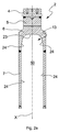
とりわけ構造の点で、図1及び2を参照すると、ビレット2には、頂部から底部へ順に以下が備わる:
−第一鉄部4;
−第二鉄部5であって、前記第一鉄部4に溶接されている第二鉄部5;
−第三銅部6であって、前記第二鉄部5に溶接されている第三銅部6;
−第四銅部7であって、前記第三銅部6に溶接されている第四銅部7。
With particular reference to FIGS. 1 and 2 in terms of construction,
-Ferrous part 4;
A second
A
The
第三銅部6は、部分的に変形しており、とりわけ、頂部から底部に向かって断面が拡大しており、それは、図2に準拠している。
The
図1及び図2が示すのは、第一部4と第二部5との間の鉄−鉄の溶接コードン(welding cordon)8;第二部5と第三部6との間の鉄−銅のコードン又は溶接線9;第三部6と第四部7との間の銅−銅の溶接コードン10である。
1 and 2 show that an iron-iron welding cordon 8 between the first part 4 and the
第四銅部7は、実質的に円筒状の管から成る。第三銅部6は、その底部に凹部13を含み、それは第三部6のより広い部分に作られる。第二鉄部5及び第三銅部6は、いわゆる「スペーサ」を規定し、該「スペーサ」は、電極の冷却領域をビレット2の鉄部から離し、該鉄部はアーク炉の運転中液体となる。固体のままとなっているビレット2の銅部と鉄部は、共に溶接され、電流の通過と熱の連続性を保証する。
The
有利なことに、冷却手段3が、少なくとも部分的に、長手方向の空洞部50内に収容されるが、該空洞部は、円筒状の管7と第三銅部6の凹部13とによって規定される。スペーサ5、6、及び円筒状の管7は、いわゆる電極ジャケットを規定する。
Advantageously, the cooling means 3 is at least partly housed in the
冷却手段3が備えるのは、好ましくは金属製の実質的に円筒の冷却ランス11であるが、該冷却ランス11は、以下の要素を備える:
−円筒状の管12であって、外径が円筒状の管7の内径よりもわずかに小さい、円筒状の管12;
−凸面又は実質的に平面の蓋14であって、前記管12の第一端を閉じるために設けられ、その外壁に、例えば単純な通過穴の形状をした複数の通路20が設けられている蓋14;
−冷却液、例えば水の運搬管19であって、前記管12の中を通り、前記蓋14と連結しており、蓋それ自身の中に納まる収集部17に通じるために連結している、運搬管19。前記管12は、好ましくは、前記運搬管19と同心である。
The cooling means 3 comprises a substantially
A
A convex or substantially
A
単純な通過穴の代わりに、通過穴の対応するネジにねじ込まれた、ネジ山の付いたノズルを設けることも可能である。 Instead of a simple passage hole, it is also possible to provide a threaded nozzle that is screwed into the corresponding screw of the passage hole .
好適変形例において、蓋14は環状要素16と連結してもよく、その中央穴18には運搬管19が挿入される。
In a preferred variant, the
有利なことに中央穴18は、収集部17に向かって広がる。有利なことに、電極の長軸Xに対して、収集部17は、管19の前記長軸Xに対する断面領域の少なくとも1.5倍の断面領域を有する。好適変形例において、収集部17の断面は、少なくとも管19の断面の2倍に等しい。
Advantageously, the
仮に管19と収集部17が、円形の断面をもつのであれば、収集部17の直径は、好ましくは、管19の直径の1.5倍に等しい。円形以外の断面の場合は、好ましくは、それぞれと等価の直径の間に、同一の関係が生じる。
If the
環状要素16は、円筒状の管12に対して、例えば溶接によって一体的に固定されている。
The
同一の蓋14が、前記環状要素16の上に、例えば溶接によって一体的に固定されていてもよく、それにより、その内部に収集部17が規定される。
The
穴が、蓋14の厚み方向に作られるが、それは、内部の収集部17を、冷却手段の外部に通じさせることによるものである。
A hole is made in the thickness direction of the
蓋14は、多かれ少なかれ頂部が押しつぶされた半球状のキャップ又はドームの形状、又は、実質的に平面のプレートの形状を持ってもよいが、冷却される電極の内部中央表面の形状に従うものである。そのようにして、凹部13の輪郭は、実質的に蓋14の外部輪郭に対応する。
The
運搬管19は、円筒状の管12から、その第二端部において突き出ているが、それは蓋14に対して反対側からであって、冷却水の注入フランジ21と結合している。
The conveying
いったん電極が組み立てられると、ランス11が電極ジャケットに収容される。凹部13の形状は、ランス11の蓋14を受け入れる形状である。あらかじめ定めた隙間又は距離Hが、凹部13と蓋14との間、冷却される電極の内部中央又は第一の表面23に設けられるが、好ましくは、電極の内部側面又は第二表面24から減少する。
Once the electrode is assembled, the
有利なことに、「湿潤表面」とも呼ばれる第一表面23と、蓋14の対応する表面との間の距離Hは、第一表面23と、穴又はノズルの排出部との間であるが、5mmから30mmの間、好ましくは、6mmから12mmの間の範囲内である。好適変形例において、距離Hは8mmに等しい。この距離Hは、空洞部50と冷却手段3又はランス11との間の間隙の第一部の幅に対応する。
Advantageously, the
管7と管12の間の路25の幅は、好ましくは2mmから12mmの間であり、路25の前記幅は、空洞部50と冷却手段3又はランス11との間の間隙の第二部の幅に対応する。
The width of the
そのような路25は、冷却水の放出管26に連結し、排出フランジ27が備わる。
Such a
穴又はノズルの直径“di”は、1mmから10mmの間の領域内にあるのが有利であって、好ましくは1mmから5mmの間の領域である。好適変形例では、直径“di”は、3mmに等しい。 Holes or Nozzle diameter "d i" is an advantageously in the region of between 1mm of 10 mm, an area of preferably between 1mm of 5 mm. In a preferred variant, the diameter “d i ” is equal to 3 mm.
その代わりに、蓋14上の穴の分布に関しては、穴の間の間隔は、Ldによって示されるが、穴の直径の関数であって、好ましくは、必須ではないが前記直径の倍数に等しい。当該分布は、蓋14の表面において、均一であっても均一でなくてもよい。間隔Ldは、穴の直径diの3倍から15倍の間の領域内にあり、好ましくは穴の直径の6倍から11倍の間の領域である。好適変形例では、Ldは31.5mmに等しい。
Instead, for the distribution of holes on the
蓋14における穴の分散の基準は、個別のジェットの攻撃によって生じる高効率の全冷却領域の一部によって冷却される第一表面23の最適カバレッジに基づく。
The criterion for the distribution of holes in the
有利なことに、排出部に接する平面に対して実質的に垂直な長軸、すなわち、第一表面23の対応部に対して実質的に垂直な長軸を有する穴が、蓋14に開けられる。
Advantageously, substantially major axis perpendicular to the plane in contact with the emissions part, i.e., holes having a substantially vertical major axis to the corresponding portion of the
更に、第一表面23又は「湿潤表面」は、平面であっても湾曲していてもよく、等価の直径Deqに関するその延長は、ビレット2の直径次第であり、約700mmの最大値を有するが、好ましくは250mmから600mmの間である。好適変形例においては、Deqは、550mmに等しい。
Furthermore, the
図6に示されるように、底部電極1のバイメタル・ビレット2は、直流連続アーク炉の耐熱炉床30に包含されている。炉床30内では、ビレット2が少なくともある種の環状耐熱継ぎ手31によって囲まれている。ビレット2の上端部32は、炉内の液体金属槽(図示されていない)と接触している。液体金属との前記接触は、ビレット自身に沿った高電流の通過の影響が伴うが、界面領域35によって隔てられた、ビレット2に沿う頂部の液体部33と底部の固体部34の構成を決定する。
As shown in FIG. 6, the
電極の冷却液は、好ましくは、必須ではないが水であり、運搬管19によってあらかじめ定められた流れで連続的に導かれ、環状要素16の中央穴18に達するまで、運搬管19に沿って流れ、蓋14内部の収集部17に達する。
The electrode coolant is preferably, but not necessarily, water and is continuously guided in a predetermined flow by the conveying
水の代わりに、他の冷却液、例えば、ナトリウムや色々な構成の共晶のような液体金属の使用をもたらすことも可能である。 Instead of water, it is also possible to bring about the use of other cooling liquids, for example liquid metals such as sodium and variously composed eutectics.
有利なことに、第一環状要素16の中央穴18は、収集部17に向かって広がっているが、それは、負荷の損失を最小限にし、収集部17内の高い圧力を回復するためである。収集部17内の冷却液の圧力は、1bargから15bargの間の範囲内にあり、好ましくは、約12bargに等しい。
Advantageously, the
収集部17は「底部収集部」とも呼ばれるが、収集部17から、液体が複数の穴を通って第一銅表面23に垂直に注入される。複数の穴を出る液体ジェットの速度vjetは、局所熱伝達に影響を及ぼすが、最大値が50m/sであり、好ましくは、25m/sから30m/sの間の領域内にある。好適変形例のプロセスでは、その速度は約27m/sに等しい。液体ジェットは、継続的に複数の穴から出るが、その速度は電極の銅部の内部表面と接触する液体の蒸発のいかなる可能性も防ぐ速度である。
The collecting
複数の穴の分散とそのプロセスのパラメータは、電極の銅部を通る最大熱流が約20MW/m2に等しくなるようなものである。 The dispersion of the holes and the process parameters are such that the maximum heat flow through the copper part of the electrode is equal to about 20 MW / m 2 .
有利なことに、一連の熱電対40が、アノードの銅スラグ(slug)の内部、とりわけ第三部分6に設置されているが(図3及び4)、それは、電極の銅部を通って発現する熱流をマッピングするためである。
Advantageously, a series of
好適変形例において、熱電対40は、電極の長軸に対して約60°傾いた角度で収容されており、その先端は前記軸に近い位置に配置されている。この熱電対40の構成は、最も熱機械的にストレスのかかる領域の一つの状態を継続的にモニタリングすることを可能にするという利点を有する。
In a preferred modification, the
更に、管7及び電極の銅部6の内部には、複数の筐体が、複数の測温抵抗体(thermoresistance)41のために設けられているが、それは、温度と故障診断のための更なる制御機器である。
Further, inside the
このように、本発明による電極の冷却システムは、冷却される第一表面23によって頂部に範囲が定められた領域、又は、「頂部収集部」において、冷却液ジェットを発生させ放出することを可能にする。
Thus, the electrode cooling system according to the present invention is capable of generating and discharging a coolant jet in an area delimited at the top by the
全てのジェットは、第一表面23の対応部に対して垂直な方向となるように制限され、「頂部収集部」と、管12と管7との間の側路25を既に満たしている同一の冷却液の中に全てが飛び込む。有利なことに、運転中、液体の通過領域のどこも空気を含まず、全てが液体自身によって占められている。従って、本発明の電極の冷却システムは、単相(水だけであって、システム内に空気を含まない)の閉じたシステムとして動作する。前記システムは、放出圧が高いか低いかには関係なく動作してもよい。
All jets are constrained to be in a direction perpendicular to the corresponding portion of the
キャップ又は穴の開いた平板の形状をした蓋14、及び、第一表面23と同キャップ又は穴の開いた平板との間の領域の構成は、第一表面23に対して液体ジェットが実質的に垂直に当たること、及び、ジェットの冷却効果が完全に乱流対流に変わった冷却システムの、放出に向かって降りてくる連続的な流れを促進するものである。
The configuration of the
液体ジェットは、アノードの冷却される頂部領域である「湿潤領域」23に当たる;電極の銅ジャケットの内部の残りの部分は、路25であるが、前記冷却される頂部領域からの液体の下降流によって冷却される(二次冷却)。
The liquid jet strikes the “wetting zone” 23, which is the cooled top region of the anode; the remaining part inside the copper jacket of the electrode is the
実験的検査によって確認されたのは、制限された液体ジェットの攻撃が、直流連続アーク炉の底部電極の銅部の高い冷却効果を得るとても効果的な手段であるということである。 Experimental testing has confirmed that the limited liquid jet attack is a very effective means of obtaining a high cooling effect on the copper portion of the bottom electrode of a DC continuous arc furnace.
平面に対して垂直に当たる乱流のジェットが、単相の伝達(空気は存在しない)の中に生じる最高の熱交換係数値の中にある、ジェットのよどみ点の近くの領域において発生した。 A turbulent jet impinging perpendicular to the plane occurred in the region near the stagnation point of the jet, with the highest heat exchange coefficient value occurring in a single phase transfer (no air present).
このパフォーマンスは、ジェットの攻撃領域内の境界層が薄くなること、そして、冷却液を、そのような領域で、交換表面と直接接触させることを可能とすることを起因とする。更に、よどみ点圧力は、ジェットが表面に当たる減速領域で記録される圧力であるが、飽和温度を大いに高め、該飽和温度とは、所与の圧力で沸騰現象が生じる温度のことである。そして、この現象を起因として、高温の壁の温度ひいては高い熱流が、よどみ領域に存在するが、これには必ずしも沸騰状態は伴わない。 This performance results from the thin boundary layer in the attack area of the jet and the ability to allow the coolant to contact the exchange surface directly in such areas. Furthermore, the stagnation point pressure is the pressure recorded in the deceleration region where the jet strikes the surface, but greatly increases the saturation temperature, which is the temperature at which boiling occurs at a given pressure. And due to this phenomenon, the temperature of the hot wall and thus the high heat flow exists in the stagnation region, but this does not necessarily involve the boiling state.
圧力と熱交換は、ジェットのよどみ点からの距離が高まるに従って、減少する。従って、表面の大部分を冷却するために、平らな表面に垂直に攻撃する一連のジェットの態様が、想起された。様々なジェットの間の流体力学は、個々のジェットの冷却状態とは大いに異なる。とりわけ、隣接するジェットからの流れのラインが一緒になる領域では、冷却される第二表面によどみ領域が生成され、そこでは、熱交換係数の局所的な増加が生じるであろう。 Pressure and heat exchange decrease as the distance from the stagnation point of the jet increases. Thus, a series of jet embodiments have been recalled that attack a flat surface vertically to cool most of the surface. The hydrodynamics between the various jets are very different from the cooling state of the individual jets. In particular, in the region where the flow lines from adjacent jets come together, a stagnation region is created in the second surface to be cooled, where a local increase in the heat exchange coefficient will occur.
このように、単一ジェットの構成に対して、液体が当たる全表面における熱交換係数の平均値の上昇が生じるが、それは、複数のジェット間の相互の距離に準じるものである。 Thus, for a single jet configuration, there is an increase in the average value of the heat exchange coefficient across the entire surface that is exposed to the liquid, according to the mutual distance between the multiple jets.
それから、前記平らな表面に実質的に垂直に当たる複数の液体ジェットを用いた解決法は、湾曲した表面、例えば、半球状の表面で有効に試験された。 Then, a solution using multiple liquid jets that hit the flat surface substantially perpendicularly has been successfully tested on curved surfaces, for example, hemispherical surfaces.
1 電極
2 ビレット
3 冷却手段
4 第一鉄部
5 第二鉄部
6 第三銅部
7 第四銅部
8 溶接コードン
9 溶接線
10 溶接コードン
11 ランス
12 管
13 凹部
14 蓋
16 環状要素
17 収集部
18 中央穴
19 管
20 穴
21 注入フランジ
23 第一表面
24 第二側表面
25 路
26 放出管
27 排出フランジ
30 炉床
31 継ぎ手
32 上端部
33 液体部
34 固体部
35 界面領域
40 熱電対
41 測温抵抗体
50 空洞部
DESCRIPTION OF
Claims (15)
−バイメタルの棒(2)であって、その長手方向に沿って、第一鉄部(4、5)であってその第一端が炉内の金属槽と接触する鉄部と、第二銅部(6、7)であって前記第一鉄部(4、5)の第二端に溶接された銅部とを備える棒(2);
−前記バイメタルの棒(2)を冷却する複数の冷却手段(3);
−前記第二銅部(6、7)内に得られる空洞部(50)であって、前記複数の冷却手段(3)が少なくとも部分的に収容される空洞部(50);
−前記空洞部(50)と前記複数の冷却手段(2)との間の間隙;
とを備え、前記複数の冷却手段(3)は、
−該複数の冷却手段(3)の第一端に設置された収集部(17)であって、該収集部(17)を、前記第一鉄部(4、5)に隣接した前記間隙の第一部に通じさせる複数の通路(20)の備わる端部壁を有する収集部(17);
−冷却液を前記収集部(17)に運ぶ第一管(19);
とを備え、
前記収集部(17)は、前記バイメタルの棒(2)の長手方向に直交する、前記第一管の断面領域の少なくとも1.5倍の断面領域を有し、
前記複数の通路(20)の各々の長手方向は実質的に、各排出部に接する平面に対して垂直であって、複数の冷却液のジェットは、前記第一鉄部(4、5)に隣接する空洞部(50)の第一表面(23)に対して実質的に垂直であって、前記間隙の前記第一部において発生していることを特徴とする電極。 An electrode for a DC electric arc furnace for melting metal, adapted to be received at the bottom of the furnace,
- a bimetal bar (2), along the longitudinal direction of that, the iron portion of the first end is in contact with the metal bath in the furnace a ferrous portion (4, 5), the second A rod (2) comprising a copper part (6, 7) and a copper part welded to the second end of the first iron part (4, 5);
A plurality of cooling means (3) for cooling said bimetallic rod (2);
A cavity (50) obtained in said second copper part (6, 7), wherein said plurality of cooling means (3) are at least partially housed;
-Gaps between the cavity (50) and the cooling means (2);
The plurality of cooling means (3) includes:
-A collecting part (17) installed at a first end of the plurality of cooling means (3), wherein the collecting part (17) is disposed in the gap adjacent to the first ferrous part (4, 5); A collection part (17) having an end wall with a plurality of passageways (20) leading to the first part;
A first pipe (19) carrying the coolant to the collecting part (17);
And
The collecting section (17) has a cross-sectional area at least 1.5 times the cross-sectional area of the first tube perpendicular to the longitudinal direction of the bimetallic rod (2) ;
The longitudinal direction of each of the plurality of passages (20) is substantially perpendicular to a plane in contact with each discharge portion, and a plurality of coolant jets are directed to the first iron portions (4, 5). Electrode characterized in that it is substantially perpendicular to the first surface (23) of the adjacent cavity (50) and occurs in the first part of the gap.
−前記空洞部(50)と前記複数の冷却手段(3)との間に備わる前記間隙を冷却液で満たすステップと;
−前記第一管(19)に冷却液を連続的に更に導くステップであって、それによって前記冷却液が前記収集部(17)に届くステップと;
−複数の冷却液ジェットの連続的な漏出による前記電極への一次冷却ステップであって、前記複数の冷却液ジェットは前記複数の通路(20)を通り、前記間隙の前記第一部の前記第一表面(23)の対応部に実質的に垂直に当たるステップと;
−それに続く前記冷却液の下降流による、前記間隙の前記第二部(25)における前記電極への二次冷却ステップと;
を有することを特徴とする、冷却プロセス。 A process for cooling an electrode according to claim 1, comprising:
Filling the gap provided between the cavity (50) and the plurality of cooling means (3) with a coolant;
-Further continuously introducing the coolant into the first pipe (19), whereby the coolant reaches the collecting part (17);
-A primary cooling step to the electrode by continuous leakage of a plurality of cooling liquid jets, the plurality of cooling liquid jets passing through the plurality of passages (20) and the first part of the gap; Hitting the corresponding part of one surface (23) substantially perpendicularly;
A subsequent secondary cooling step to the electrode in the second part (25) of the gap by the subsequent downward flow of the coolant;
A cooling process characterized by comprising:
Applications Claiming Priority (3)
| Application Number | Priority Date | Filing Date | Title |
|---|---|---|---|
| ITMI2009A002192A IT1396945B1 (en) | 2009-12-15 | 2009-12-15 | ELECTRODE FOR DIRECT CURRENT ELECTRIC OVEN |
| ITMI2009A002192 | 2009-12-15 | ||
| PCT/EP2010/069730 WO2011073244A1 (en) | 2009-12-15 | 2010-12-15 | Electrode for direct current continuous arc furnace |
Publications (3)
| Publication Number | Publication Date |
|---|---|
| JP2013513924A JP2013513924A (en) | 2013-04-22 |
| JP2013513924A5 JP2013513924A5 (en) | 2014-01-30 |
| JP5475143B2 true JP5475143B2 (en) | 2014-04-16 |
Family
ID=42246016
Family Applications (1)
| Application Number | Title | Priority Date | Filing Date |
|---|---|---|---|
| JP2012543712A Active JP5475143B2 (en) | 2009-12-15 | 2010-12-15 | Electrodes for DC continuous arc furnaces. |
Country Status (12)
| Country | Link |
|---|---|
| US (1) | US9335097B2 (en) |
| EP (1) | EP2513581B1 (en) |
| JP (1) | JP5475143B2 (en) |
| KR (1) | KR101398663B1 (en) |
| CN (1) | CN102656415B (en) |
| ES (1) | ES2444620T3 (en) |
| IT (1) | IT1396945B1 (en) |
| MX (1) | MX2012006907A (en) |
| MY (1) | MY159297A (en) |
| RU (1) | RU2516116C2 (en) |
| UA (1) | UA102203C2 (en) |
| WO (1) | WO2011073244A1 (en) |
Families Citing this family (5)
| Publication number | Priority date | Publication date | Assignee | Title |
|---|---|---|---|---|
| AT13590U1 (en) * | 2012-10-22 | 2014-04-15 | Plansee Se | Glass melting electrode with cooling device and cooling device for a glass melting electrode |
| US20220236007A1 (en) * | 2019-06-07 | 2022-07-28 | Pyrogenesis Canada Inc. | Non-water cooled consumable electrode vacuum arc furnace for continuous process |
| CN112781226B (en) * | 2020-03-06 | 2022-04-22 | 青岛经济技术开发区海尔热水器有限公司 | Water heater |
| CN111947151A (en) * | 2020-08-07 | 2020-11-17 | 合肥中科远望环保科技有限公司 | Gas composite plasma torch |
| US11956921B1 (en) * | 2020-08-28 | 2024-04-09 | Frore Systems Inc. | Support structure designs for MEMS-based active cooling |
Family Cites Families (9)
| Publication number | Priority date | Publication date | Assignee | Title |
|---|---|---|---|---|
| SU568222A1 (en) * | 1972-08-21 | 1977-08-05 | Предприятие П/Я М-5385 | Hearth electrode |
| SE419929B (en) * | 1974-11-25 | 1981-08-31 | Asea Ab | MELT CONTACT ELECTROD |
| US4101725A (en) * | 1976-08-16 | 1978-07-18 | Nikolai Semenovich Shelepov | Hearth electrode for melting furnaces |
| FR2566984B1 (en) * | 1984-06-27 | 1986-12-19 | Siderurgie Fse Inst Rech | ELECTRICAL CONNECTION DEVICE FOR PLACING ON THE WALL OF A METALLURGICAL CONTAINER IN CONTACT WITH MOLTEN METAL |
| JPH03124198U (en) * | 1990-03-24 | 1991-12-17 | ||
| JP2946619B2 (en) * | 1990-03-27 | 1999-09-06 | 大同特殊鋼株式会社 | Bottom electrode of DC arc furnace |
| CN2150508Y (en) * | 1992-08-29 | 1993-12-22 | 冶金部鞍山热能研究院 | Cooper-steel composite water-cooling AC electric-arc furnace floor positive electrode |
| CN1049044C (en) * | 1995-03-30 | 2000-02-02 | 冶金工业部钢铁研究总院 | Bottom electrode of d.c arc furnace |
| DE29602191U1 (en) * | 1996-02-08 | 1996-03-21 | Badische Stahl-Engineering GmbH, 77694 Kehl | Bottom electrode |
-
2009
- 2009-12-15 IT ITMI2009A002192A patent/IT1396945B1/en active
-
2010
- 2010-12-15 MY MYPI2012002717A patent/MY159297A/en unknown
- 2010-12-15 WO PCT/EP2010/069730 patent/WO2011073244A1/en active Application Filing
- 2010-12-15 JP JP2012543712A patent/JP5475143B2/en active Active
- 2010-12-15 KR KR1020127018453A patent/KR101398663B1/en active IP Right Grant
- 2010-12-15 ES ES10803070.1T patent/ES2444620T3/en active Active
- 2010-12-15 CN CN201080056170.1A patent/CN102656415B/en active Active
- 2010-12-15 UA UAA201208188A patent/UA102203C2/en unknown
- 2010-12-15 RU RU2012129987/02A patent/RU2516116C2/en not_active IP Right Cessation
- 2010-12-15 MX MX2012006907A patent/MX2012006907A/en active IP Right Grant
- 2010-12-15 EP EP10803070.1A patent/EP2513581B1/en active Active
- 2010-12-15 US US13/261,323 patent/US9335097B2/en active Active
Also Published As
| Publication number | Publication date |
|---|---|
| ITMI20092192A1 (en) | 2011-06-16 |
| ES2444620T3 (en) | 2014-02-26 |
| KR20120099490A (en) | 2012-09-10 |
| UA102203C2 (en) | 2013-06-10 |
| CN102656415B (en) | 2015-04-15 |
| EP2513581B1 (en) | 2013-11-06 |
| KR101398663B1 (en) | 2014-05-30 |
| CN102656415A (en) | 2012-09-05 |
| EP2513581A1 (en) | 2012-10-24 |
| JP2013513924A (en) | 2013-04-22 |
| MY159297A (en) | 2016-12-30 |
| US9335097B2 (en) | 2016-05-10 |
| MX2012006907A (en) | 2012-10-05 |
| RU2012129987A (en) | 2014-01-27 |
| US20120269225A1 (en) | 2012-10-25 |
| WO2011073244A1 (en) | 2011-06-23 |
| IT1396945B1 (en) | 2012-12-20 |
| RU2516116C2 (en) | 2014-05-20 |
Similar Documents
| Publication | Publication Date | Title |
|---|---|---|
| JP5475143B2 (en) | Electrodes for DC continuous arc furnaces. | |
| US4207060A (en) | Vessel for metal smelting furnace | |
| EP1413174B1 (en) | Furnace with mounting arrangement for auxiliary burner or lance | |
| CN104964559A (en) | Bottom ring for submerged arc furnace and manufacturing method for bottom ring | |
| KR100342274B1 (en) | Cooling Plate for Furnace | |
| CA1265179A (en) | Electrode structure for a bath of molten metal | |
| RU2769337C1 (en) | Copper mold plate and continuous casting mold | |
| US4646316A (en) | Electric connecting device for contacting a molten metallic mass | |
| CN209623363U (en) | Muzzle tile assembly and metallurgical furnace kiln with it | |
| JP2005505742A (en) | Melt washing tank | |
| KR100631326B1 (en) | Method and device for operating electric arc furnaces and/or resistance furnaces | |
| US6849228B2 (en) | Blowing lance nozzle | |
| CN109654885B (en) | Muzzle brick assembly and metallurgical furnace with same | |
| BRPI0211234B1 (en) | ASSEMBLY ARRANGEMENT FOR BURNER OR AUXILIARY LAUNCH | |
| CN2913381Y (en) | Combined forging and pressing oxygen lance nozzle | |
| CN202894532U (en) | Aluminum brazing preheating furnace circulating fan | |
| CN217131782U (en) | Electric arc furnace heat shielding device and electric arc furnace | |
| JPH11201650A (en) | Furnace wall structure of electric melting furnace and cooling method for furnace body | |
| RU2450228C1 (en) | Holder of injector and method of its operation | |
| JP3678379B2 (en) | Electric arc furnace electrode support device | |
| CN110461053A (en) | Dumping furnace smelts Brown Alundum self-baking electrode cooling system | |
| JP2946619B2 (en) | Bottom electrode of DC arc furnace | |
| JPH06174382A (en) | Dc arc furnace | |
| CN206872906U (en) | BOTTOM OXYGEN gun platform | |
| JP3102255B2 (en) | Graphite electrode cooling device for arc furnace |
Legal Events
| Date | Code | Title | Description |
|---|---|---|---|
| A131 | Notification of reasons for refusal |
Free format text: JAPANESE INTERMEDIATE CODE: A131 Effective date: 20130828 |
|
| A977 | Report on retrieval |
Free format text: JAPANESE INTERMEDIATE CODE: A971007 Effective date: 20130830 |
|
| A521 | Request for written amendment filed |
Free format text: JAPANESE INTERMEDIATE CODE: A523 Effective date: 20131127 |
|
| A524 | Written submission of copy of amendment under article 19 pct |
Free format text: JAPANESE INTERMEDIATE CODE: A524 Effective date: 20131127 |
|
| TRDD | Decision of grant or rejection written | ||
| A01 | Written decision to grant a patent or to grant a registration (utility model) |
Free format text: JAPANESE INTERMEDIATE CODE: A01 Effective date: 20140108 |
|
| A61 | First payment of annual fees (during grant procedure) |
Free format text: JAPANESE INTERMEDIATE CODE: A61 Effective date: 20140205 |
|
| R150 | Certificate of patent or registration of utility model |
Ref document number: 5475143 Country of ref document: JP Free format text: JAPANESE INTERMEDIATE CODE: R150 Free format text: JAPANESE INTERMEDIATE CODE: R150 |
|
| R250 | Receipt of annual fees |
Free format text: JAPANESE INTERMEDIATE CODE: R250 |
|
| R250 | Receipt of annual fees |
Free format text: JAPANESE INTERMEDIATE CODE: R250 |
|
| R250 | Receipt of annual fees |
Free format text: JAPANESE INTERMEDIATE CODE: R250 |
|
| R250 | Receipt of annual fees |
Free format text: JAPANESE INTERMEDIATE CODE: R250 |
|
| R250 | Receipt of annual fees |
Free format text: JAPANESE INTERMEDIATE CODE: R250 |
|
| R250 | Receipt of annual fees |
Free format text: JAPANESE INTERMEDIATE CODE: R250 |
|
| R250 | Receipt of annual fees |
Free format text: JAPANESE INTERMEDIATE CODE: R250 |
|
| R250 | Receipt of annual fees |
Free format text: JAPANESE INTERMEDIATE CODE: R250 |