JP5474635B2 - Refrigeration equipment - Google Patents
Refrigeration equipment Download PDFInfo
- Publication number
- JP5474635B2 JP5474635B2 JP2010078316A JP2010078316A JP5474635B2 JP 5474635 B2 JP5474635 B2 JP 5474635B2 JP 2010078316 A JP2010078316 A JP 2010078316A JP 2010078316 A JP2010078316 A JP 2010078316A JP 5474635 B2 JP5474635 B2 JP 5474635B2
- Authority
- JP
- Japan
- Prior art keywords
- imti
- inlet side
- side temperature
- refrigerant
- temperature
- Prior art date
- Legal status (The legal status is an assumption and is not a legal conclusion. Google has not performed a legal analysis and makes no representation as to the accuracy of the status listed.)
- Expired - Fee Related
Links
Images


Landscapes
- Air Conditioning Control Device (AREA)
Description
本発明は、所定の制御特性によって調整される第1の冷媒流と第2の冷媒流とを備え、高圧側が超臨界圧力となる冷凍装置に関するものである。 The present invention relates to a refrigeration apparatus that includes a first refrigerant flow and a second refrigerant flow that are adjusted according to predetermined control characteristics, and has a high-pressure side at a supercritical pressure.
従来よりこの種冷凍装置は、圧縮手段、ガスクーラ、絞り手段等から冷凍サイクルが構成され、圧縮手段で圧縮された冷媒がガスクーラにて放熱し、絞り手段にて減圧された後、蒸発器にて冷媒を蒸発させて、このときの冷媒の蒸発により周囲の空気を冷却するものとされていた。近年、この種冷凍装置では、自然環境問題などからフロン系冷媒が使用できなくなってきている。このため、フロン冷媒の代替品として自然冷媒である二酸化炭素を使用するものが開発されている。当該二酸化炭素冷媒は、高低圧差の激しい冷媒で、臨界圧力が低く、圧縮により冷媒サイクルの高圧側が超臨界状態となることが知られている(例えば、特許文献1参照)。 Conventionally, this type of refrigeration apparatus has a refrigeration cycle composed of a compression means, a gas cooler, a throttle means, etc., and the refrigerant compressed by the compression means dissipates heat in the gas cooler and is depressurized by the throttle means, and then in an evaporator. The refrigerant was evaporated, and ambient air was cooled by evaporation of the refrigerant at this time. In recent years, chlorofluorocarbon refrigerants cannot be used in this type of refrigeration system due to natural environmental problems. For this reason, the thing using the carbon dioxide which is a natural refrigerant | coolant is developed as a substitute of a fluorocarbon refrigerant | coolant. The carbon dioxide refrigerant is a refrigerant having a high and low pressure difference, and has a low critical pressure. It is known that the high pressure side of the refrigerant cycle is brought into a supercritical state by compression (see, for example, Patent Document 1).
係る超臨界冷媒サイクルでは、ガスクーラ側の熱源温度(例えば、ガスクーラと熱交換する熱媒体である外気温度)が高い等の原因により、ガスクーラ出口の冷媒温度が高くなる条件下においては、蒸発器入口の比エンタルピが大きくなるため、冷凍効果が著しく低下する問題が生じていた。この場合、冷凍能力を確保するには、高圧圧力を上昇させる必要があるため、圧縮動力が増大して、成績係数も低下するという不都合が生じる。 In such a supercritical refrigerant cycle, under conditions where the refrigerant temperature at the gas cooler outlet becomes high due to a high heat source temperature on the gas cooler side (for example, the outside air temperature as a heat medium that exchanges heat with the gas cooler), the evaporator inlet Since the specific enthalpy of the slag increased, there was a problem that the refrigeration effect was significantly reduced. In this case, in order to ensure the refrigerating capacity, it is necessary to increase the high-pressure pressure, which causes a disadvantage that the compression power increases and the coefficient of performance also decreases.
このため、ガスクーラで冷却された冷媒を2つの冷媒流に分流し、分流された一方の冷媒流(第1の冷媒流)を補助絞り手段で絞った後に中間熱交換器の一方の通路(第1の流路)に流し、もう一方の冷媒流(第2の冷媒流)を中間熱交換器の前記第1の流路と交熱的に設けられた他方の流路(第2の流路)に流した後、主絞り手段を介して蒸発器にて蒸発させる所謂スプリットサイクル(二段圧縮一段膨張中間冷凍サイクル)の冷凍装置が提案されている。 For this reason, the refrigerant cooled by the gas cooler is divided into two refrigerant flows, one of the divided refrigerant flows (first refrigerant flow) is throttled by the auxiliary throttle means, and then one of the passages of the intermediate heat exchanger (first passage) 1) and the other refrigerant flow (second refrigerant flow) is exchanged with the first flow channel of the intermediate heat exchanger in a heat exchange manner (second flow channel). ), And a so-called split-cycle (two-stage compression, one-stage expansion intermediate refrigeration cycle) refrigeration apparatus that evaporates in an evaporator via a main throttle means has been proposed.
上述のスプリットサイクル装置では、ガスクーラで放熱した後の冷媒を分流し、減圧膨張された第1の冷媒流により、第2の冷媒流を冷却することができるようになり、蒸発器入口の比エンタルピを小さくすることができるようになる。これにより、冷凍効果を大きくすることが可能となり、従来の装置に比べて効果的に性能を向上させることができるようになる。しかし、第2の冷媒流を減圧する前に冷却するための第1の冷媒流による冷却効果は、中間熱交換器を流れる第1の冷媒流と第2の冷媒流の量に依存する。 In the split cycle apparatus described above, the refrigerant after radiating heat from the gas cooler is diverted, and the second refrigerant flow can be cooled by the first refrigerant flow that has been decompressed and expanded. Can be reduced. As a result, the refrigeration effect can be increased and the performance can be effectively improved as compared with the conventional apparatus. However, the cooling effect of the first refrigerant flow for cooling the second refrigerant flow before depressurization depends on the amount of the first refrigerant flow and the second refrigerant flow flowing through the intermediate heat exchanger.
即ち、第1の冷媒流の量が多すぎれば蒸発器において最終的に蒸発する第2の冷媒流の量が不足することになり、逆に第1の冷媒流の量が少なすぎれば、第1の冷媒流による冷却効果(即ち、スプリットサイクルの効果)が薄れてくる。一方、補助絞り手段で減圧された第1の冷媒流の圧力は冷媒回路の中間圧力側の圧力であり、この中間圧力側の圧力を制御することは、第1の冷媒流の量を制御することになる。そのため、最適な性能改善効果を得るためには、これら冷媒流を適切に制御する必要がある。
That is, if the amount of the first refrigerant flow is too large, the amount of the second refrigerant flow that finally evaporates in the evaporator will be insufficient. Conversely, if the amount of the first refrigerant flow is too small, The cooling effect (that is, the effect of the split cycle) due to the
本発明は、従来の技術的課題を解決するために成されたものであり、安定した補助絞り手段の制御を行うことで、冷凍装置の冷媒回路の中間圧力の適正化を図ることにより、スプリットサイクルの効果が的確に得られ、それによって冷凍装置の性能を向上させることを目的とする。 The present invention has been made to solve the conventional technical problems, and by controlling the auxiliary throttle means stably, by optimizing the intermediate pressure of the refrigerant circuit of the refrigeration apparatus, The object is to accurately obtain the effect of the cycle, thereby improving the performance of the refrigeration apparatus.
上記課題を解決するために、本発明の冷凍装置は、圧縮手段と、ガスクーラと、補助絞り手段と、中間熱交換器と、主絞り手段と、蒸発器とから冷媒回路を構成し、ガスクーラから出た冷媒を二つの流れに分流して、第1の冷媒流を補助絞り手段を経て中間熱交換器の第1の流路に流し、第2の冷媒流を中間熱交換器の第2の流路に流した後、主絞り手段を経て蒸発器に流すことにより、中間熱交換器にて第1の冷媒流と第2の冷媒流とを熱交換させ、蒸発器から出た冷媒を圧縮手段の低圧部に吸い込ませ、中間熱交換器から出た第1の冷媒流を圧縮手段の中間圧部に吸い込ませると共に、高圧側圧力HPが超臨界圧力となり得るものであって、補助絞り手段の開度を制御する制御手段と、中間熱交換器の第1の流路の入口側温度IMTIを検出するための入口側温度検出手段と、外気温度ATを検出するための外気温度検出手段とを備え、制御手段は、所定のサンプリング周期で入口側温度検出手段及び外気温度検出手段により入口側温度IMTI及び外気温度ATを取り込み、外気温度ATに基づき、所定の関数式を用いて入口側温度IMTIの目標値STを算出すると共に、この入口側温度IMTIが目標値STに近い範囲にある安定時には、入口側温度IMTIが目標値STとなるよう、圧縮手段を停止する際にのみ補助絞り手段の開度を制御し、圧縮手段の運転中は、補助絞り手段の開度を維持することを特徴とする。 In order to solve the above problems, a refrigeration apparatus of the present invention comprises a refrigerant circuit including a compression means, a gas cooler, an auxiliary throttle means, an intermediate heat exchanger, a main throttle means, and an evaporator. The refrigerant that has exited is divided into two flows, the first refrigerant stream is passed through the auxiliary throttle means to the first flow path of the intermediate heat exchanger, and the second refrigerant stream is passed through the second flow of the intermediate heat exchanger. After flowing through the flow path, the first refrigerant flow and the second refrigerant flow are exchanged in the intermediate heat exchanger by flowing into the evaporator through the main throttle means, and the refrigerant discharged from the evaporator is compressed. The first refrigerant flow from the intermediate heat exchanger is sucked into the intermediate pressure part of the compression means, and the high pressure side pressure HP can be a supercritical pressure, and the auxiliary throttle means A control means for controlling the opening degree of the inlet, and an inlet side temperature IMTI of the first flow path of the intermediate heat exchanger An inlet side temperature detecting means for detecting the outside air temperature AT, and an outside air temperature detecting means for detecting the outside air temperature AT. The control means uses the inlet side temperature detecting means and the outside air temperature detecting means at a predetermined sampling period. The IMTI and the outside air temperature AT are taken in, the target value ST of the inlet side temperature IMTI is calculated using a predetermined function formula based on the outside air temperature AT, and when the inlet side temperature IMTI is in a range close to the target value ST The opening degree of the auxiliary throttle means is controlled only when the compression means is stopped so that the inlet temperature IMTI becomes the target value ST, and the opening degree of the auxiliary throttle means is maintained during operation of the compression means. And
請求項2の発明は、上記において、制御手段は、入口側温度IMTIと目標値STとの差の絶対値が所定値KF未満であるときに安定時と判断することを特徴とする。 The invention of claim 2 is characterized in that, in the above, the control means determines that the time is stable when the absolute value of the difference between the inlet side temperature IMTI and the target value ST is less than a predetermined value KF.
請求項3の発明は、上記各発明において、制御手段は、圧縮手段の運転中における安定時に入口側温度IMTIの平均値AVTを算出し、当該平均値AVTに基づき、補助絞り手段の開度を制御することを特徴とする。 According to the invention of claim 3, in each of the above inventions, the control means calculates an average value AVT of the inlet side temperature IMTI when the compression means is stable during operation, and the opening degree of the auxiliary throttle means is calculated based on the average value AVT. It is characterized by controlling.
請求項4の発明は、上記各発明において、制御手段は、圧縮手段を起動する際の補助絞り手段の開度制御を、当該圧縮手段の起動から所定時間遅延させて実行することを特徴とする。
The invention of
請求項5の発明は、上記各発明において、制御手段は、安定時以外の不安定時においては、入口側温度IMTIが目標値STに近づくようサンプリング周期で補助絞り手段の開度を制御すると共に、入口側温度IMTIが目標値STよりも高い不安定時であって、当該入口側温度IMTIが下降傾向である場合には、補助絞り手段の開度を維持することを特徴とする。
According to the invention of
請求項6の発明は、上記各発明において、制御手段は、外気温度ATをxとし、入口側温度IMTIの目標値STをyとする一次関数を用いて当該目標値STを算出すると共に、該一次関数は、冷媒回路の高圧側圧力HPが超臨界領域にある場合と飽和領域にある場合とで傾きが異なることを特徴とする。
According to the invention of
請求項7の発明は、上記各発明において、冷媒として二酸化炭素を使用したことを特徴とする。
The invention of
本発明によれば、補助絞り手段の開度を制御する制御手段と、中間熱交換器の第1の流路の入口側温度IMTIを検出するための入口側温度検出手段と、外気温度ATを検出するための外気温度検出手段とを備え、制御手段は、所定のサンプリング周期で入口側温度検出手段及び外気温度検出手段により入口側温度IMTI及び外気温度ATを取り込み、外気温度ATに基づき、所定の関数式を用いて入口側温度IMTIの目標値STを算出すると共に、この入口側温度IMTIが目標値STに近い範囲にある安定時、例えば、請求項2の発明の如く、入口側温度IMTIと目標値STとの差の絶対値が所定値KF未満であるときには、入口側温度IMTIが目標値STとなるよう、圧縮手段を停止する際にのみ補助絞り手段の開度を制御し、圧縮手段の運転中は、補助絞り手段の開度を維持することにより、圧縮手段の運転によって細かく変動する中間圧力に影響されることなく、圧縮手段の停止のタイミングにて補助絞り手段を安定して開度制御することが可能となる。 According to the present invention, the control means for controlling the opening degree of the auxiliary throttle means, the inlet side temperature detecting means for detecting the inlet side temperature IMTI of the first flow path of the intermediate heat exchanger, and the outside air temperature AT. An outside air temperature detecting means for detecting, and the control means takes in the inlet side temperature IMTI and the outside air temperature AT by the inlet side temperature detecting means and the outside air temperature detecting means at a predetermined sampling period, and determines the predetermined temperature based on the outside air temperature AT. The target value ST of the inlet side temperature IMTI is calculated using the following functional expression, and when the inlet side temperature IMTI is in a range close to the target value ST, for example, as in the invention of claim 2, the inlet side temperature IMTI When the absolute value of the difference between the value and the target value ST is less than the predetermined value KF, the opening degree of the auxiliary throttle means is controlled only when the compression means is stopped so that the inlet side temperature IMTI becomes the target value ST. During operation of the compression means, the opening of the auxiliary throttle means is maintained, so that the auxiliary throttle means is stabilized at the stop timing of the compression means without being affected by the intermediate pressure that varies finely depending on the operation of the compression means. Thus, the opening degree can be controlled.
これにより、他の機器、即ち、圧縮手段の運転周波数や主絞り手段の開度制御などによって、相互に影響を与える当該冷凍装置において、安定した補助絞り手段の開度制御を実現でき、これによって、適正な中間圧力を実現し、冷却効率の向上を図ることが可能となる。 This makes it possible to realize stable opening control of the auxiliary throttle means in the refrigeration apparatus that affects each other by the operation frequency of the compression means, the opening control of the main throttle means, and the like. Therefore, it is possible to achieve an appropriate intermediate pressure and improve the cooling efficiency.
また、請求項3の発明によれば、上記各発明に加えて、制御手段は、圧縮手段の運転中における安定時に入口側温度IMTIの平均値AVTを算出し、当該平均値AVTに基づき、補助絞り手段の開度を制御することにより、より精度の高い制御を実現することが可能となる。 According to the invention of claim 3, in addition to the above inventions, the control means calculates the average value AVT of the inlet side temperature IMTI when the compression means is in stable operation, and based on the average value AVT, the auxiliary means By controlling the opening degree of the aperture means, it is possible to realize more accurate control.
請求項4の発明によれば、上記各発明に加えて、制御手段は、圧縮手段を起動する際の補助絞り手段の開度制御を、当該圧縮手段の起動から所定時間遅延させて実行するので、圧縮手段の起動と、補助絞り手段の開度制御が同時に行われることによる不具合を効果的に回避しつつ、安定した補助絞り手段の開度制御を実現することが可能となる。
According to the invention of
請求項5の発明によれば、上記各発明に加えて、制御手段は、安定時以外の不安定時においては、入口側温度IMTIが目標値STに近づくようサンプリング周期で補助絞り手段の開度を制御すると共に、入口側温度IMTIが目標値STよりも高い不安定時であって、当該入口側温度IMTIが下降傾向である場合には、補助絞り手段の開度を維持するので、入口側温度IMTIが下降傾向である場合にも、補助絞り手段の開度を制御すると、より絞る方向に制御されてしまい、最終的に弁開度が殆ど閉じたしまった状況を招来することとなるが、このような不具合を解消でき、早期に入口側温度IMTIが目標値STに近似した安定時とすることが可能となる。
According to the invention of
請求項6の発明によれば、上記各発明に加えて、制御手段は、外気温度ATをxとし、入口側温度IMTIの目標値STをyとする一次関数を用いて当該目標値STを算出すると共に、該一次関数は、冷媒回路の高圧側圧力HPが超臨界領域にある場合と飽和領域にある場合とで傾きが異なるので、外気温度によって、高圧側圧力HPが超臨界領域や飽和領域となる請求項7の発明の如き二酸化炭素を冷媒として使用した場合であっても、高圧側圧力HPの状況に追従して、入口側温度IMTIの目標値STを変更することで、外気温度ATに応じて中間圧力の適正化を実現することができる。
According to the invention of
以下、図面に基づき本発明の実施形態を詳述する。図1は本発明の冷凍装置10を適用する実施例としての業務用冷凍庫(低温貯蔵庫)Rの縦断側面図を示している。実施例の冷凍庫Rは、例えばホテルやレストランの厨房などに設置されるものであり、前面開口22が扉6にて開閉自在に閉塞される断熱箱体1により本体が構成されている。
Hereinafter, embodiments of the present invention will be described in detail with reference to the drawings. FIG. 1: has shown the vertical side view of the commercial freezer (low temperature storage) R as an Example which applies the
この断熱箱体1は、何れもステンレスなどの鋼板から成る外箱2、及び、この外箱2内に組み込まれた内箱3と、内外両箱2、3間に現場発泡方式にて充填されたポリウレタン断熱材4から構成されている。そして、この断熱箱体1(内箱3)内を貯蔵室(被冷却空間)5としている。
The
また、貯蔵室5内上部には、本願発明にかかる冷凍装置10の蒸発器11と冷気循環用送風機12が取り付けられる冷却室14が仕切板13によって区画形成されている。冷気循環用送風機12より貯蔵室5から冷却室14に吸い込まれた冷気は、蒸発器11と熱交換された後、冷却室14後方の開口から吐出されて、貯蔵室5内は所定の温度に冷却される。
In addition, a cooling
一方、断熱箱体1の天面には前面パネル16及び両側面及び後面を構成するパネルによって機械室17が画成されており、この機械室17内には冷凍装置10を構成する圧縮機(圧縮手段)18やガスクーラ19などが設置され、蒸発器11と共に冷凍装置10の周知の冷凍サイクルを構成している。20は、放熱器用送風機である。
On the other hand, a
ここで、図2の冷媒回路図を参照して本実施例における冷凍装置10の冷媒回路7について説明する。本実施例における冷凍装置10の冷凍サイクルには、冷媒として二酸化炭素が封入されており、高圧側の冷媒圧力(高圧圧力)がその臨界圧力以上(超臨界)となるスプリットサイクル(二段圧縮一段膨張中間冷却サイクル)を採用する。
Here, the
本実施例の冷凍装置10は、圧縮機(圧縮手段)18を構成する低段側の圧縮要素(低段側圧縮手段)18Aと、同じく圧縮手段を構成する高段側の圧縮要素(高段側圧縮手段)18Bと、ガスクーラ19と、分流器37と、合流器38と、補助絞り手段としての補助膨張弁39と、中間熱交換器40と、内部熱交換器41と、主絞り手段としての膨張弁8と、蒸発器11とから冷媒回路7が構成されている。
The refrigerating
上記ガスクーラ19は高段側の圧縮要素18Bから出た高温高圧の冷媒を放熱させることによって、当該高段側の圧縮要素18Bから出た冷媒を冷却する。分流器37は、ガスクーラ19から出た冷媒を第1の冷媒流と第2の冷媒流とに分流し、第1の冷媒流を副回路42に流し、第2の冷媒流を主回路43に流す。
The
第2の冷媒流が流れる主回路43は、分流器37にて分流された冷媒が、中間熱交換器40の内管(第2の流路)40B、内部熱交換器41の内管41B、ストレーナ44、膨張弁8、蒸発器11、内部熱交換器41の外管41A、逆止弁45が介設された冷媒導入管23、及びストレーナ46を順次通り、低段側圧縮手段を構成する圧縮要素18Aの吸込側(低圧部)へ供給されるように接続されている。
In the
第1の冷媒流が流れる副回路42は、分流器37にて分流された冷媒が、ストレーナ47、補助膨張弁39及び中間熱交換器40の外管(第1の流路)40Aを順次通り、高段側圧縮手段を構成する圧縮要素18Bの吸込側(中間圧部)へ供給されるように接続されている。
In the sub-circuit 42 through which the first refrigerant flow flows, the refrigerant diverted by the
本実施例における圧縮機18は、冷媒を低段側圧縮手段としての圧縮要素18Aと、高段側圧縮手段としての圧縮要素18Bが単一の密閉容器内に収納される内部中間圧二段圧縮式ロータリ圧縮機を採用している。これら圧縮要素18A、18Bは、同一の密閉容器内に収納される圧縮機モータ(電動要素。DCモータ)により駆動される。
The
次に、図3を参照して本実施例における冷凍装置10の制御装置(制御手段)9について説明する。制御装置9は、汎用のマイクロコンピュータにより構成されており、時限手段としてのタイマ32、演算処理部33、記憶部34を内蔵している。
Next, the control device (control means) 9 of the
制御装置9には、各種設定スイッチや表示部などを備えたコントロールパネル35が接続されている。各種設定スイッチには、詳細は後述する如く各設定値を任意に設定可能とするLCDパネル(設定手段)36も含まれる。
A
また、当該制御装置9の入力側には、庫内の現在温度を検出する庫内温度センサ(現在温度検出手段)31、蒸発器11の冷媒入口温度を検出するための蒸発器入口温度センサ29、蒸発器11の冷媒出口温度を検出するための蒸発器出口温度センサ30、中間熱交換器40の外管(第1の流路)40Aの入口側温度IMTIを検出するための入口側温度センサ(入口側温度検出手段)49、外気温度ATを検出するための外気温度センサ(外気温度検出手段)48等が接続されている。
Further, on the input side of the
他方、制御装置9の出力側には、圧縮機18を駆動させる圧縮機モータ(DCモータ)18Mと、冷気循環用送風機12を駆動させる送風機モータ12M、放熱器用送風機20を駆動させる送風機モータ20M、膨張弁8、補助膨張弁39等が接続されている。
On the other hand, on the output side of the
圧縮機モータ18Mは、インバータ装置25を介して接続されており、これによって、圧縮機モータ18Mの運転周波数を任意に変更可能とされている。送風機モータ12M、20Mは、それぞれチョッパ回路などの駆動回路26、27を介して接続されており、これによって、回転数を任意に変更可能とされている。
The
また、膨張弁8及び補助膨張弁39は、それぞれ、制御装置Cから出力される駆動電圧のパルス数に応じて、内蔵のステッピングモータを任意の角度だけ回転させ、この回転量を弁体の弁座に対する進退移動量に変換することにより、弁開度が調整される。
Further, the
以上の構成により、制御装置9により冷凍装置10が運転されると、圧縮機18の低段側圧縮要素18Aの吸込側(低圧部)に取り込まれた冷媒は、ここで中間圧まで昇圧される。この低段側圧縮要素18Aにて圧縮された冷媒は、図示しない連通管より密閉容器内に吐出される。
With the above configuration, when the
一端が密閉容器内にて開放した冷媒導入管は高段側圧縮要素18Bの吸込側に設けられており、低段圧縮要素18Aにて中間圧まで昇圧された冷媒と、合流器38を経た副回路42からの中間圧冷媒とが混合された冷媒が、当該冷媒導入管より高段側圧縮要素18B(中間圧部)内に流入され、ここで更に所定の高圧まで昇圧される。
The refrigerant introduction pipe whose one end is opened in the closed container is provided on the suction side of the high-
このとき、この高段側圧縮要素18Bにて圧縮された冷媒の圧力(高圧側圧力HP)は、超臨界圧力とされ、当該超臨界状態の冷媒は、冷媒吐出管24を介して、ガスクーラ19に流入される。尚、本実施例では、前記圧縮機18を構成する各圧縮要素18A、18Bは単一のモータで一体に結合された構成としているが、これに限定されない。
At this time, the pressure of the refrigerant compressed by the high-
ガスクーラ19を出た冷媒は通過する過程で冷却された後、分流器37に入り、第1の冷媒流が流れる副回路42と、第2の冷媒流が流れる主回路43とに分流される。副回路42に流入した第1の冷媒流は、補助膨張弁39で中間圧(即ち、低段側圧縮要素18Aの吐出圧力であり、高段側圧縮要素18Bの吸込圧力と略同圧)まで減圧される。
The refrigerant that has exited the
そして、中間熱交換器40の外管(第1の流路)40A内を通過し、当該外管(第1の流路)40A内を通過する過程で、内管40Bを通過する分流器37で分流された後の他方の冷媒流である第2の冷媒流と熱交換して蒸発する。その後、合流器38にて、低段側の圧縮要素18Aで圧縮された後の第2の冷媒流と合流して、高段側圧縮要素18B(中間圧部)に吸い込まれる。
Then, in the process of passing through the outer pipe (first flow path) 40A of the
一方、主回路43に流入した第2の冷媒流は、中間熱交換器40の内管(第2の流路)40B内を通過する過程で、補助膨張弁39によって減圧された第1の冷媒流と熱交換して冷却された後、内部熱交換器41の内管(第2の流路)41B内を通過する。当該内管(第2の流路)41B内を通過する過程で、外管(第1の流路)41A内を流れる蒸発器11から出た冷媒と熱交換して冷却される。
On the other hand, the second refrigerant flow flowing into the
そして、内部熱交換器40から流出された第1の冷媒流は、膨張弁8にて蒸発圧力まで減圧された後、蒸発器11内に流入し貯蔵室5内(被冷却空間)を熱源として蒸発し、内部熱交換器41の外管41Aを経て低段側の圧縮要素18(低圧部)に吸い込まれる。ここで、内部熱交換器41により、膨張弁8に流入する冷媒は、蒸発器11から流出した低温冷媒と熱交換されることで、冷却性能の向上を図ることができる。
The first refrigerant flow that has flowed out of the
このように、本実施例の冷凍装置10は、冷媒として自然冷媒であり、臨界圧力が低く、冷媒サイクルの高圧が超臨界状態となる二酸化炭素を使用するものである。そのため、環境への負荷軽減を図ることができると共に、冷却能力の確保を図ることができる。また、ガスクーラ19で冷却された後の冷媒を分流し、減圧膨張させた一方の副回路42を流れる第1の冷媒流により、分流された他方の主回路43を流れる第2の冷媒流を冷却する、所謂、スプリットサイクル冷却装置を用いることで、蒸発器11の入口の比エンタルピを小さくし、冷凍効果を大きくすることが可能となる。
As described above, the
このように、冷凍装置10が運転されると、冷却室14にて蒸発器11と熱交換された冷気は、冷気循環用送風機12により貯蔵室5に吐出されて、貯蔵室5内を循環した後、再び送風機12によって冷却室14内に帰還する循環を行う。
As described above, when the
このとき、制御装置9は、庫内温度センサ31により検出される庫内の現在温度を冷却目標温度とするように、また、蒸発器11における過熱度(蒸発器入口側温度と蒸発器出口側温度との差)が所定の適正値となるように、圧縮機モータ18Mの運転周波数制御及び、膨張弁8の開度制御を行う。また、制御装置9は、上記圧縮機18の周波数制御に加えて庫内温度センサ31により検出される現在の庫内温度が冷却目標温度より所定温度高い上限温度に達した場合、圧縮機モータ18Mを起動し、冷却目標温度よりも所定温度低い下限温度に達した場合、圧縮機モータ18Mを停止するサーモサイクルを行い、庫内温度を冷却目標温度に制御する。
At this time, the
次に、本実施例における冷凍装置10の補助膨張弁39の弁開度制御について図4の制御説明図を参照して説明する。制御装置9は、先ず、所定のサンプリング周期で入口側温度センサ49にて中間熱交換器40の外管(第1の流路)40Aの入口側温度IMTIを検出し、外気温度センサ48にて外気温度ATを検出し、記憶部34に取り込む。
Next, valve opening control of the
そして、上述したように取得した現在の入口側温度IMTIと、外気温度ATとから入口側温度の目標値STを算出する。このとき、制御装置9は、外気温度ATに基づき、所定の関数式を用いて中間熱交換器40の外管(第1の流路)40Aの入口側温度IMTIの目標値STを算出する。
Then, the target value ST of the inlet side temperature is calculated from the current inlet side temperature IMTI acquired as described above and the outside air temperature AT. At this time, the
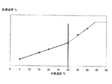
本実施例では、図5の外気温度ATに対する目標値STとの関係を示す図に示すように、制御装置9は、外気温度ATをxとし、入口側温度IMTIの目標値STをyとする一次関数を用いて目標値STを算出する。当該関数式は、予め制御装置9の記憶部34に記憶されているものである。
In the present embodiment, as shown in the diagram showing the relationship between the outside air temperature AT and the target value ST in FIG. 5, the
本実施例では、冷媒として高圧側圧力HPが超臨界領域となる二酸化炭素を用いているため、当該一次関数(関数式)は、冷媒回路の高圧側圧力HPが超臨界領域にある場合と飽和領域にある場合とで傾きが異なる。具体的には、図6に示すように、当該二酸化炭素の超臨界温度付近、一例として外気温度ATが30℃以上では、30℃未満の場合と比べて、その関数式の傾きが大きくなる。 In this embodiment, carbon dioxide whose high-pressure side pressure HP is in the supercritical region is used as the refrigerant. Therefore, the linear function (function formula) is saturated when the high-pressure side pressure HP of the refrigerant circuit is in the supercritical region. The slope is different depending on the area. Specifically, as shown in FIG. 6, the slope of the functional expression becomes larger when the ambient temperature AT is near 30 ° C. or more, for example, near the supercritical temperature of the carbon dioxide, compared to the case of less than 30 ° C.
これは、冷媒として二酸化炭素を用いた場合、外気温度ATが30℃以上では、高圧側圧力HPが超臨界領域となるため、高圧側圧力HPが飽和領域となる外気温度ATが30℃未満の場合と比べて、外気温度ATの上昇による適正な中間圧力の変動が大きくなる。そのため、高圧側圧力の状況に追従して、中間圧力を適正とすべく、入口側温度IMTIの目標値STを変更する。 This is because, when carbon dioxide is used as the refrigerant, the high pressure side pressure HP is in the supercritical region when the outside air temperature AT is 30 ° C. or higher, and therefore the outside air temperature AT in which the high pressure side pressure HP is in the saturation region is less than 30 ° C. Compared to the case, the fluctuation of the appropriate intermediate pressure due to the increase in the outside air temperature AT becomes larger. Therefore, the target value ST of the inlet side temperature IMTI is changed so that the intermediate pressure is appropriate following the state of the high pressure side pressure.
以上より、制御装置9は、取り込んだ外気温度ATから上記一次関数を用いて、当該外気温度ATに対する中間熱交換器40の入口側温度IMTIの目標値STを取得する。そして、制御装置9は、取得された目標値STと、先ほど検出されて取り込まれた入口側温度IMTIとを比較し、現在の中間熱交換器40の入口側温度の変化状態が安定時であるか不安定時であるかを判断する。
As described above, the
具体的には、入口側温度IMTIと目標値STとの差(IMTI−ST)の絶対値が所定値KF未満である場合(差が±KF未満の場合)は安定時と判断し、当該差(IMTI−ST)の絶対値が所定値KF以上である場合(差が±KF以上の場合)は、不安定時と判断する。ここで、所定値KFとは、一例として3℃とする。尚、所定値KFは、3℃に限られず、任意に設定可能とする。 Specifically, when the absolute value of the difference between the inlet temperature IMTI and the target value ST (IMTI-ST) is less than a predetermined value KF (when the difference is less than ± KF), it is determined that the time is stable, and the difference When the absolute value of (IMTI-ST) is greater than or equal to the predetermined value KF (when the difference is greater than or equal to ± KF), it is determined that the time is unstable. Here, the predetermined value KF is 3 ° C. as an example. The predetermined value KF is not limited to 3 ° C. and can be set arbitrarily.
上記において、制御装置9により、入口側温度IMTIが目標値STに近い範囲にある安定時であると判断した場合には、図4に示すように、圧縮機18を停止する際にのみ補助膨張弁39の開度を制御することする。即ち、圧縮機18の運転中、停止中には、補助膨張弁39の開度は、現状を維持することとする。
In the above description, when the
このときの補助膨張弁39の開度制御は、圧縮機18の運転中における安定時に入口側温度IMTIの平均値AVTに基づき行う。即ち、制御装置9は、現在の圧縮機18が運転している状態において所定のサンプリング周期で入口側温度センサ49により検出された入口側温度IMTIを取り込み、当該運転中における入口側温度IMTIの平均値AVTを算出する。
At this time, the opening degree control of the
また、制御装置9は、同様のサンプリング周期で取り込まれた外気温度センサ48により検出された外気温度ATを取り込み、当該運転中における外気温度ATの平均値AVATを算出する。当該算出された外気温度ATの平均値AVATに基づき、上述したように、入口側温度IMTIの目標値STを算出する。
Further, the
そして、制御装置9は、入口側温度IMTIの平均値AVTが上述の如く算出された目標値STとなるような補助膨張弁39の開度を算出する。このとき、入口側温度IMTIの平均値AVTが目標値STから高いほど補助膨張弁39の弁開度をより絞る方向に、低いほど弁開度をより開く方向に操作量のパルス制御を行う。
Then, the
尚、当該安定時における補助膨張弁39の弁開度制御は、前回の入口側温度IMTIと今回の入口側温度IMTIとの差から判断される入口側温度IMTIが上昇傾向であるか下降傾向であるかにかかわらず、上記制御を行う。
In addition, the valve opening degree control of the
一方、制御装置9により、入口側温度IMTIが目標値STに近い範囲でない不安定時であると判断した場合には、図4に示すように、不安定時と判断した時点で、補助膨張弁39の開度を制御する(条件成立都度制御)。
On the other hand, when the
このとき、制御装置9は、今回の入口側温度IMTIと目標値STとの差が上記所定値KFより大きい所定値KE以上であるか否かを判断する。ここで、所定値KEとは、一例として、上記所定値KFより大きい8℃とする。尚、所定値KEは、8℃に限られず、任意に設定可能とする。
At this time, the
そして、上記において、制御装置9は、所定のサンプリング周期で取り込まれた入口側温度IMTIが目標値STよりも所定値KE以上高い場合であって、前回の入口側温度IMTIと今回の入口側温度IMTIとの差から判断される入口側温度IMTIが上昇傾向である場合には、当該入口側温度IMTIが、外気温度ATから算出される目標値STに所定値KFを加えた温度となるような補助膨張弁39の開度を算出する。
In the above, the
このとき、制御装置9は、入口側温度IMTIが目標値ST+所定値KFから高いほど補助膨張弁39の弁開度をより絞る方向に操作量のパルス制御を行う。また、このとき、オーバーシュートを防止するため、当該算出された操作量に所定の係数、例えば1/2〜1/20の間で任意に設定された係数を乗じた操作量としても良い。
At this time, the
尚、この場合、入口側温度IMTIが目標値ST+所定値KFより高い不安定時であって、下降傾向である場合には、補助膨張弁39の弁開度を維持し、制御しないものとする。
In this case, when the inlet side temperature IMTI is unstable higher than the target value ST + the predetermined value KF and tends to decrease, the opening degree of the
そして、制御装置9は、今回の入口側温度IMTIと目標値STとの差が上記所定値KE以下であって所定値KE以上である場合であって、前回の入口側温度IMTIと今回の入口側温度IMTIとの差から判断される入口側温度IMTIが上昇傾向である場合には、当該入口側温度IMTIが、外気温度ATから算出される目標値STとなるような補助膨張弁39の開度を算出する。
Then, the
このとき、制御装置9は、入口側温度IMTIが目標値STから高いほど補助膨張弁39の弁開度をより絞る方向に操作量のパルス制御を行う。また、このときも、オーバーシュートを防止するため、当該算出された操作量に所定の係数、例えば1/2〜1/20の間で任意に設定された係数を乗じた操作量としても良い。
At this time, the
尚、この場合も、入口側温度IMTIが入口側温度IMTIが目標値STより高い不安定時であって、下降傾向である場合には、補助膨張弁39の弁開度を維持し、制御しないものとする。
In this case as well, when the inlet side temperature IMTI is unstable when the inlet side temperature IMTI is higher than the target value ST and tends to decrease, the valve opening degree of the
他方、制御装置9は、今回の入口側温度IMTIが目標値STより所定値KF以上低い場合(IMTI<ST−KF)には、入口側温度IMTIが上昇傾向であるか下降傾向であるか否かにかかわらず、当該入口側温度IMTIが、外気温度ATから算出される目標値STとなるような補助膨張弁39の開度を算出する。
On the other hand, when the current inlet side temperature IMTI is lower than the target value ST by a predetermined value KF or more (IMTI <ST-KF), the
このとき、制御装置9は、入口側温度IMTIが目標値STから低いほど補助膨張弁39の弁開度をより拡張させる方向に操作量のパルス制御を行う。また、このときも、オーバーシュートを防止するため、当該算出された操作量に所定の係数、例えば1/2〜1/20の間で任意に設定された係数を乗じた操作量としても良い。
At this time, the
通常、上述したようなスプリットサイクル冷却装置では、第1の冷媒流の量と第2の冷媒流の量とを最適に調整することで、第1の冷媒流による冷却効果を向上させるべく、補助膨張弁39により減圧される第1の冷媒流の圧力、即ち、冷媒回路の中間圧力を制御する。
In general, in the split cycle cooling device as described above, the amount of the first refrigerant flow and the amount of the second refrigerant flow are optimally adjusted so as to improve the cooling effect by the first refrigerant flow. The pressure of the first refrigerant flow reduced by the
従来では、この際、中間熱交換器40の外管(第1の流路)40Aを流れる第1の冷媒流の入口側温度IMTIを検出し、当該入口側温度IMTIが予め設定された目標値となるように開閉制御していた。しかし、適正な中間圧力を実現する入口側温度IMTIの目標値は、外気温度ATによって異なるものであり、適切な補助膨張弁39の開度制御が困難であった。
Conventionally, at this time, the inlet side temperature IMTI of the first refrigerant flow flowing through the outer pipe (first flow path) 40A of the
また、この場合、制御装置は、圧縮機18の運転状況にかかわらず、所定のサンプリング周期にて取り込まれる入口側温度IMTIが目標値となるように、その都度、補助膨張弁39の開度制御を行っていたが、第1の冷媒流の流れは、圧縮機18の運転に大きく影響を受ける。また、補助膨張弁39の開度制御が行われることによって、冷媒回路7の中間圧力を制御していたが、これによって、膨張弁8の開度制御や、圧縮機18の運転周波数制御に影響を与えることとなり、それぞれの設定値の変更が生じる。そのため、圧縮機の運転状況が変化することで、中間圧力も変化し、結果として、安定した中間圧力の実現ができない。
Further, in this case, the control device controls the opening degree of the
これに対し、上述したように、本発明では、圧縮機18を停止する際にのみ補助膨張弁39の開度を制御し、圧縮機18の運転中は、補助膨張弁39の開度を現状のまま維持することとしたので、圧縮機18の運転によって、細かく変動する中間圧力に影響されることなく、圧縮機18の起動のタイミングや停止のタイミングにて補助膨張弁39を安定して開度制御することが可能となる。
On the other hand, as described above, according to the present invention, the opening degree of the
これにより、他の機器、即ち、圧縮手段の運転周波数や主絞り手段の開度制御などによって、相互に影響を与える当該冷凍装置において、安定した補助絞り手段の開度制御を実現でき、これによって、適正な中間圧力を実現し、冷却効率の向上を図ることが可能となる。 This makes it possible to realize stable opening control of the auxiliary throttle means in the refrigeration apparatus that affects each other by the operation frequency of the compression means, the opening control of the main throttle means, and the like. Therefore, it is possible to achieve an appropriate intermediate pressure and improve the cooling efficiency.
また、本発明では、制御装置9は、圧縮機18の運転中における安定時に入口側温度IMTIの平均値AVTを算出し、当該平均値AVTに基づき、補助膨張弁39の開度を制御するので、上記においてより精度の高い制御を実現することが可能となる。
In the present invention, the
また、上記実施例では、制御装置9は、安定時以外の不安定時においては、入口側温度IMTIが目標値STに近づくようサンプリング周期で補助膨張弁39の開度を制御すると共に、入口側温度IMTIが目標値STよりも高い不安定時であって、当該入口側温度IMTIが下降傾向である場合には、補助膨張弁39の開度を維持する。そのため、入口側温度IMTIが下降傾向である場合にも、補助膨張弁39の開度が制御されると、より絞る方向に制御されてしまい、最終的に弁開度が殆ど閉じたしまった状況を招来することとなるが、このような不具合を解消でき、早期に入口側温度IMTIが目標値STに近似した安定時とすることが可能となる。
In the above embodiment, the
更に、本実施例では、入口側温度IMTIの目標値STを外気温度ATをxとし、入口側温度IMTIの目標値STをyとする一次関数を用いて当該目標値STを算出する。そして、この一次関数は、冷媒回路の高圧側圧力HPが超臨界領域にある場合と飽和領域にある場合とで傾きが異なるものを採用している。 Further, in the present embodiment, the target value ST is calculated using a linear function in which the target value ST of the inlet side temperature IMTI is the outside air temperature AT, and the target value ST of the inlet side temperature IMTI is y. And this linear function employ | adopts the thing from which the inclination differs by the case where the high voltage | pressure side pressure HP of a refrigerant circuit exists in a supercritical area | region, and the case where it exists in a saturation area | region.
そのため、本実施例のように冷媒として二酸化炭素を用いた場合には、外気温度ATが30℃以上では、高圧側圧力HPが超臨界領域となり、高圧側圧力HPが飽和領域となる外気温度ATが30℃未満の場合と比べて、外気温度ATの上昇による適正な中間圧力の変動が大きくなるが、高圧側圧力の状況に追従して、入口側温度IMTIの目標値STを変更することで、外気温度ATに応じて中間圧力の適正化を実現することができる。 Therefore, when carbon dioxide is used as the refrigerant as in this embodiment, when the outside air temperature AT is 30 ° C. or higher, the outside air temperature AT at which the high pressure side pressure HP is in the supercritical region and the high pressure side pressure HP is in the saturation region. Compared with the case where the temperature is less than 30 ° C., the appropriate intermediate pressure fluctuates due to the increase in the outside air temperature AT, but the target value ST of the inlet side temperature IMTI is changed by following the high pressure side pressure situation. In addition, the intermediate pressure can be optimized according to the outside air temperature AT.
尚、上記実施例では、安定時以外の不安定時において圧縮機18を起動する際の補助膨張弁39の開度制御は、圧縮機18を起動するタイミングと同時に行っているが、これに限定されるものではなく、圧縮機18の起動から所定時間、例えば、1分乃至5分で設定された任意の時間、遅延させて実行してもよい。これにより、圧縮機18の起動と、補助膨張弁39の開度制御が同時に行われることによる不具合を効果的に回避しつつ、安定した補助膨張弁39の開度制御を実現することが可能となる。
In the above embodiment, the opening degree control of the
R 業務用冷凍庫(低温貯蔵庫)
1 断熱箱体
5 貯蔵室(被冷却空間)
7 冷媒回路
8 膨張弁(主絞り手段)
9 制御装置
10 冷凍装置
11 蒸発器
18 圧縮機(圧縮手段)
18A 低段側圧縮要素(低段側圧縮手段)
18B 高段側圧縮要素(高段側圧縮手段)
19 ガスクーラ
35 コントロールパネル
36 LCDパネル(設定手段)
39 補助膨張弁(補助絞り手段)
40 中間熱交換器
41 内部熱交換器
42 副回路
43 主回路
48 外気温度センサ(外気温度検出手段)
49 入口側温度センサ(入口側温度検出手段)
R Commercial freezer (low temperature storage)
1
7
9
18A Low stage compression element (Low stage compression means)
18B High stage compression element (High stage compression means)
19 Gas cooler 35
39 Auxiliary expansion valve (auxiliary throttle means)
40
49 Inlet side temperature sensor (Inlet side temperature detecting means)
Claims (7)
前記補助絞り手段の開度を制御する制御手段と、
前記中間熱交換器の第1の流路の入口側温度IMTIを検出するための入口側温度検出手段と、
外気温度ATを検出するための外気温度検出手段とを備え、
前記制御手段は、所定のサンプリング周期で前記入口側温度検出手段及び外気温度検出手段により前記入口側温度IMTI及び外気温度ATを取り込み、前記外気温度ATに基づき、所定の関数式を用いて前記入口側温度IMTIの目標値STを算出すると共に、
当該入口側温度IMTIが目標値STに近い範囲にある安定時には、
前記入口側温度IMTIが前記目標値STとなるよう、前記圧縮手段を停止する際にのみ前記補助絞り手段の開度を制御し、前記圧縮手段の運転中は、前記補助絞り手段の開度を維持することを特徴とする冷凍装置。 The compression means, the gas cooler, the auxiliary throttle means, the intermediate heat exchanger, the main throttle means, and the evaporator constitute a refrigerant circuit, and the refrigerant discharged from the gas cooler is divided into two flows, and the first The refrigerant flow is passed through the auxiliary throttle means to the first flow path of the intermediate heat exchanger, the second refrigerant flow is flowed to the second flow path of the intermediate heat exchanger, and then the main throttle means The first refrigerant flow and the second refrigerant flow are exchanged in the intermediate heat exchanger, and the refrigerant discharged from the evaporator is transferred to the low pressure portion of the compression means. In the refrigerating apparatus in which the first refrigerant flow discharged from the intermediate heat exchanger is sucked into the intermediate pressure part of the compression means and the high pressure side pressure HP can be a supercritical pressure.
Control means for controlling the opening of the auxiliary throttle means;
Inlet side temperature detection means for detecting the inlet side temperature IMTI of the first flow path of the intermediate heat exchanger;
An outside air temperature detecting means for detecting the outside air temperature AT,
The control unit takes in the inlet side temperature IMTI and the outside air temperature AT by the inlet side temperature detecting unit and the outside air temperature detecting unit at a predetermined sampling period, and uses the predetermined function formula based on the outside air temperature AT to While calculating the target value ST of the side temperature IMTI,
When the inlet side temperature IMTI is in a range close to the target value ST,
The opening degree of the auxiliary throttle means is controlled only when the compression means is stopped so that the inlet side temperature IMTI becomes the target value ST. During operation of the compression means, the opening degree of the auxiliary throttle means is controlled. A refrigeration apparatus characterized by maintaining.
前記入口側温度IMTIが前記目標値STよりも高い前記不安定時であって、当該入口側温度IMTIが下降傾向である場合には、前記補助絞り手段の開度を維持することを特徴とする請求項1乃至請求項4のうちの何れかに記載の冷凍装置。 The control means controls the opening of the auxiliary throttle means at the sampling period so that the inlet side temperature IMTI approaches the target value ST when unstable other than the stable time,
The opening of the auxiliary throttle means is maintained when the inlet side temperature IMTI is higher than the target value ST and the inlet side temperature IMTI tends to decrease. The refrigeration apparatus according to any one of claims 1 to 4.
該一次関数は、前記冷媒回路の高圧側圧力HPが超臨界領域にある場合と飽和領域にある場合とで傾きが異なることを特徴とする請求項1乃至請求項5のうちの何れかに記載の冷凍装置。 The control means calculates the target value ST using a linear function in which the outside air temperature AT is x and the target value ST of the inlet side temperature IMTI is y.
6. The linear function according to claim 1, wherein the slope of the linear function varies depending on whether the high pressure side pressure HP of the refrigerant circuit is in a supercritical region or a saturated region. Refrigeration equipment.
Priority Applications (1)
| Application Number | Priority Date | Filing Date | Title |
|---|---|---|---|
| JP2010078316A JP5474635B2 (en) | 2010-03-30 | 2010-03-30 | Refrigeration equipment |
Applications Claiming Priority (1)
| Application Number | Priority Date | Filing Date | Title |
|---|---|---|---|
| JP2010078316A JP5474635B2 (en) | 2010-03-30 | 2010-03-30 | Refrigeration equipment |
Publications (2)
| Publication Number | Publication Date |
|---|---|
| JP2011208894A JP2011208894A (en) | 2011-10-20 |
| JP5474635B2 true JP5474635B2 (en) | 2014-04-16 |
Family
ID=44940141
Family Applications (1)
| Application Number | Title | Priority Date | Filing Date |
|---|---|---|---|
| JP2010078316A Expired - Fee Related JP5474635B2 (en) | 2010-03-30 | 2010-03-30 | Refrigeration equipment |
Country Status (1)
| Country | Link |
|---|---|
| JP (1) | JP5474635B2 (en) |
Cited By (1)
| Publication number | Priority date | Publication date | Assignee | Title |
|---|---|---|---|---|
| CN106524546A (en) * | 2015-09-11 | 2017-03-22 | 松下知识产权经营株式会社 | Refrigeration apparatus |
Families Citing this family (1)
| Publication number | Priority date | Publication date | Assignee | Title |
|---|---|---|---|---|
| CN116202255A (en) * | 2023-01-16 | 2023-06-02 | 华涧新能源科技(上海)有限公司 | Supercooling degree control method for energy storage thermal management system |
Family Cites Families (4)
| Publication number | Priority date | Publication date | Assignee | Title |
|---|---|---|---|---|
| JPS476276Y1 (en) * | 1969-10-30 | 1972-03-04 | ||
| US7631510B2 (en) * | 2005-02-28 | 2009-12-15 | Thermal Analysis Partners, LLC. | Multi-stage refrigeration system including sub-cycle control characteristics |
| JP5144959B2 (en) * | 2007-05-25 | 2013-02-13 | 三菱重工業株式会社 | Heat source machine and control method thereof |
| JP2009014210A (en) * | 2007-06-29 | 2009-01-22 | Daikin Ind Ltd | Refrigeration equipment |
-
2010
- 2010-03-30 JP JP2010078316A patent/JP5474635B2/en not_active Expired - Fee Related
Cited By (2)
| Publication number | Priority date | Publication date | Assignee | Title |
|---|---|---|---|---|
| CN106524546A (en) * | 2015-09-11 | 2017-03-22 | 松下知识产权经营株式会社 | Refrigeration apparatus |
| CN106524546B (en) * | 2015-09-11 | 2021-11-09 | 松下知识产权经营株式会社 | Refrigerating device |
Also Published As
| Publication number | Publication date |
|---|---|
| JP2011208894A (en) | 2011-10-20 |
Similar Documents
| Publication | Publication Date | Title |
|---|---|---|
| US8474280B2 (en) | Refrigerating storage cabinet and control method for compressor thereof | |
| US11226145B2 (en) | Refrigerator and method for controlling a compressor based on temperature of storage compartment | |
| US11371768B2 (en) | Refrigerator and method for controlling the same | |
| KR20110072441A (en) | Refrigerator and its operation control method | |
| JP2011149613A (en) | Cooling device | |
| KR20170067559A (en) | A refrigerator and a method for controlling the same | |
| JP2007218460A (en) | Refrigeration cycle equipment and cold storage | |
| JP5602519B2 (en) | Refrigeration equipment | |
| JP2013064573A (en) | Refrigerating apparatus for container | |
| KR100569891B1 (en) | How to control blower fan of refrigerator | |
| JP5856435B2 (en) | refrigerator | |
| JP5474635B2 (en) | Refrigeration equipment | |
| JP2010060181A (en) | Refrigeration system | |
| JP5585245B2 (en) | Refrigeration equipment | |
| JP5554161B2 (en) | Refrigeration equipment | |
| JP2007010220A (en) | Refrigerating unit and refrigerator comprising the same | |
| JP5862867B2 (en) | refrigerator | |
| JP6166771B2 (en) | refrigerator | |
| KR102255294B1 (en) | A refrigerator | |
| KR20200082221A (en) | Refrigerator and method for controlling the same | |
| KR102153056B1 (en) | A refrigerator and a control method the same | |
| KR20120003224A (en) | Refrigerant circulation system of refrigeration unit | |
| KR102144467B1 (en) | A refrigerator and a control method the same | |
| JP2004085106A (en) | Refrigerator and cold storage | |
| KR102157544B1 (en) | Refrigerator |
Legal Events
| Date | Code | Title | Description |
|---|---|---|---|
| A621 | Written request for application examination |
Free format text: JAPANESE INTERMEDIATE CODE: A621 Effective date: 20130313 |
|
| A977 | Report on retrieval |
Free format text: JAPANESE INTERMEDIATE CODE: A971007 Effective date: 20131218 |
|
| TRDD | Decision of grant or rejection written | ||
| A01 | Written decision to grant a patent or to grant a registration (utility model) |
Free format text: JAPANESE INTERMEDIATE CODE: A01 Effective date: 20140107 |
|
| A61 | First payment of annual fees (during grant procedure) |
Free format text: JAPANESE INTERMEDIATE CODE: A61 Effective date: 20140205 |
|
| R150 | Certificate of patent or registration of utility model |
Ref document number: 5474635 Country of ref document: JP Free format text: JAPANESE INTERMEDIATE CODE: R150 Free format text: JAPANESE INTERMEDIATE CODE: R150 |
|
| LAPS | Cancellation because of no payment of annual fees |