JP5468809B2 - Method for producing heat exchanger for exhaust gas made of aluminum and its heat exchanger - Google Patents
Method for producing heat exchanger for exhaust gas made of aluminum and its heat exchanger Download PDFInfo
- Publication number
- JP5468809B2 JP5468809B2 JP2009099919A JP2009099919A JP5468809B2 JP 5468809 B2 JP5468809 B2 JP 5468809B2 JP 2009099919 A JP2009099919 A JP 2009099919A JP 2009099919 A JP2009099919 A JP 2009099919A JP 5468809 B2 JP5468809 B2 JP 5468809B2
- Authority
- JP
- Japan
- Prior art keywords
- exhaust gas
- brazing material
- heat exchanger
- brazing
- aluminum
- Prior art date
- Legal status (The legal status is an assumption and is not a legal conclusion. Google has not performed a legal analysis and makes no representation as to the accuracy of the status listed.)
- Active
Links
Images


Classifications
-
- Y—GENERAL TAGGING OF NEW TECHNOLOGICAL DEVELOPMENTS; GENERAL TAGGING OF CROSS-SECTIONAL TECHNOLOGIES SPANNING OVER SEVERAL SECTIONS OF THE IPC; TECHNICAL SUBJECTS COVERED BY FORMER USPC CROSS-REFERENCE ART COLLECTIONS [XRACs] AND DIGESTS
- Y02—TECHNOLOGIES OR APPLICATIONS FOR MITIGATION OR ADAPTATION AGAINST CLIMATE CHANGE
- Y02T—CLIMATE CHANGE MITIGATION TECHNOLOGIES RELATED TO TRANSPORTATION
- Y02T10/00—Road transport of goods or passengers
- Y02T10/10—Internal combustion engine [ICE] based vehicles
- Y02T10/12—Improving ICE efficiencies
Landscapes
- Exhaust-Gas Circulating Devices (AREA)
Description
本発明は、ガソリンエンジンまたはディーゼルエンジンの熱機関から排出される排ガスを主として冷却水で冷却する熱交換器に関し、特に排気再循環装置に用いられる排気ガスを冷却する熱交換器(EGRクーラ)或いは排熱回収用に最適なものである。 The present invention relates to a heat exchanger that mainly cools exhaust gas discharged from a heat engine of a gasoline engine or a diesel engine with cooling water, and in particular, a heat exchanger (EGR cooler) that cools exhaust gas used in an exhaust gas recirculation device or It is optimal for exhaust heat recovery.
排ガス用熱交換器であるEGRクーラは、それぞれインナーフィンを有する多数のチューブを有し、そのチューブ内に排ガスが流通すると共にチューブの外面側に冷却水を流通させて、熱交換を行うものである。そのとき、排ガスが冷却水により冷却され、チューブ内には腐食性凝縮水が付着する。そのため、耐食性を確保するため、排ガスが流通するチューブおよびインナーフィンはステンレス材とする必要があった。なお、ガスが流通するものであっても、凝縮水が生成しないインタークーラではアルミニウム材を使用していた。また、チューブは一般に偏平チューブを用い、インナーフィンとしてストレートフィン、ウェーブフィン、オフセットフィンを用いていた。 The EGR cooler, which is a heat exchanger for exhaust gas, has a large number of tubes each having an inner fin. Exhaust gas circulates in the tubes and cooling water is circulated on the outer surface side of the tubes to perform heat exchange. is there. At that time, the exhaust gas is cooled by the cooling water, and corrosive condensed water adheres in the tube. Therefore, in order to ensure corrosion resistance, the tubes and inner fins through which the exhaust gas circulates need to be made of stainless steel. In addition, even if gas circulates, an aluminum material is used in an intercooler that does not generate condensed water. Moreover, the tube used the flat tube generally, and used the straight fin, the wave fin, and the offset fin as the inner fin.
ステンレス製EGRクーラは、偏平チューブを一対の溝状部材を逆向きに嵌着し、その内面にニッケル(Ni)ろうの粉末をバインダーを介して付着させ、内部にインナーフィンを装着していた。その偏平チューブとヘッダとの間にも同様にNiろうを付着させ、全体を組立てて、炉内で一体にろう付け固定していた。
そのため、そのろう材の付着工程が複雑になると共に、高価なNiろう、その他の材料を必要とし、結果、EGRクーラが高価にならざるをえなかった。
インタークーラでは、ステンレス材の代わりにアルミニウム材を使用して、そのチューブの内面側にろう材がクラッドされたアルミニウム製クラッド材を用い、インナーフィンにはろう材の付着されていないベア材を用い、それらを組立てていた。
アルミニウム製熱交換器をEGRクーラに用いた場合には、ステンレス製熱交換器のような粉末ろうの塗布工程は不要となり、製造原価が低下することができる。しかし、排ガスが流通する偏平チューブ内に腐食性凝縮水が生成すると、それにより腐食が起こり、寿命が短いものとならざるをえなかった。
In the stainless steel EGR cooler, a pair of groove-like members are fitted in a flat tube in opposite directions, nickel (Ni) braze powder is attached to the inner surface of the flat tube via a binder, and an inner fin is attached inside. Similarly, Ni brazing was adhered between the flat tube and the header, and the whole was assembled and brazed and fixed integrally in the furnace.
Therefore, the adhesion process of the brazing material becomes complicated, and expensive Ni brazing and other materials are required. As a result, the EGR cooler has to be expensive.
In the intercooler, aluminum material is used instead of stainless steel, aluminum clad material with brazing material clad on the inner surface of the tube is used, and bare material with no brazing material is used for the inner fin. And assembled them.
When an aluminum heat exchanger is used for the EGR cooler, a powder brazing process such as a stainless heat exchanger is not necessary, and the manufacturing cost can be reduced. However, when corrosive condensed water is generated in the flat tube through which the exhaust gas flows, corrosion has occurred, and the life has to be shortened.
そこで、本発明はステンレス製熱交換器に比べて、各素材が安価で且つ製造しやすいアルミニウム製熱交換器であっても、腐食性凝縮水に耐えうる熱交換器の製造方法およびその熱交換器を提供することを課題とする。 Therefore, the present invention is a method of manufacturing a heat exchanger that can withstand corrosive condensate, and its heat exchange, even if each material is an aluminum heat exchanger that is inexpensive and easy to manufacture compared to a stainless steel heat exchanger. It is an object to provide a vessel.
請求項1に記載の本発明は、端部を排ガスタンク(1)に連通させた複数の偏平チューブ(2)が並列され、その偏平チューブ(2) の内部にインナーフィン(3) が介装され、その偏平チューブ(2) 内に腐食性凝縮水が生成される排ガス用熱交換器の製造方法において、
それぞれアルミニウム製で、前記偏平チューブ(2) 材及び排ガスタンク(1)の少なくとも内面側全面にZnを1.5〜3.0%含むろう材が被覆されると共に、インナーフィン(3) 材の両面の全面にZnを1.0〜2.0%を含むろう材が被覆された各部品を組み立てる工程と、その組み立体を炉内に挿入して、前記ろう材を溶融し、次いでそれを固化して、各部品間を一体にろう付け固定すると共に、その偏平チューブ(2) の内面全体およびインナーフィン(3) の全体及び排ガスタンク(1)の内面全体を固化した前記ろう材で被覆する工程とを有することを特徴とするアルミニウム製排ガス用熱交換器の製造方法である。
In the first aspect of the present invention, a plurality of flat tubes (2) whose ends communicate with the exhaust gas tank (1) are arranged in parallel, and an inner fin (3) is interposed in the flat tube (2). In the method of manufacturing a heat exchanger for exhaust gas in which corrosive condensed water is generated in the flat tube (2),
Each made of aluminum, the brazing material containing 1.5 to 3.0% Zn is coated on at least the entire inner surface side of the flat tube (2) material and the exhaust gas tank (1) , and the entire surface of both surfaces of the inner fin (3) material. A process of assembling each part coated with a brazing material containing 1.0 to 2.0% of Zn, and inserting the assembled solid body into a furnace to melt the brazing material, and then solidifying it, between each part And brazing and fixing together, and covering the entire inner surface of the flat tube (2), the entire inner fin (3), and the entire inner surface of the exhaust gas tank (1) with the solidified brazing material. It is a manufacturing method of the heat exchanger for exhaust gas made from aluminum.
請求項2に記載の本発明は、端部を排ガスタンク(1) に連通させた複数の偏平チューブ(2) が並列され、その偏平チューブ(2) の内部にインナーフィン(3) が介装され、その偏平チューブ(2) 内に腐食性凝縮水が生成される排ガス用熱交換器の製造方法において、
それぞれアルミニウム製で、前記偏平チューブ(2) 材の内面側にZnを1.5〜3.5%含むろう材が被覆されると共に、インナーフィン(3) 材の両面にZnを1.0〜1.5%を含むろう材が被覆された各部品を組み立てる工程と、その組み立体を炉内に挿入して、前記ろう材を溶融し、次いでそれを固化して、各部品間を一体にろう付け固定すると共に、その偏平チューブ(2) の内面全体およびインナーフィン(3) の全体を固化した前記ろう材で被覆する工程とを有することを特徴とするアルミニウム製排ガス用熱交換器の製造方法である。
According to the present invention, a plurality of flat tubes (2) whose ends are connected to the exhaust gas tank (1) are arranged in parallel, and an inner fin (3) is interposed in the flat tube (2). In the method of manufacturing a heat exchanger for exhaust gas in which corrosive condensed water is generated in the flat tube (2),
Each brazing material made of aluminum and coated with a brazing material containing 1.5 to 3.5% Zn on the inner surface side of the flat tube (2) material, and containing 1.0 to 1.5% Zn on both sides of the inner fin (3) material A step of assembling each of the parts coated with, and inserting the assembly into the furnace to melt the brazing material, then solidifying it, brazing and fixing the parts together, and flattening the parts And a step of coating the entire inner surface of the tube (2) and the entire inner fin (3) with the solidified brazing material.
請求項3に記載の本発明は、端部を排ガスタンク(1) に連通させた複数の偏平チューブ(2) が並列され、その偏平チューブ(2) の内部にインナーフィン(3) が介装され、その偏平チューブ(2) 内に腐食性凝縮水が生成される排ガス用熱交換器の製造方法において、
それぞれアルミニウム製で、前記偏平チューブ(2) 材の内面側にZnを1.5〜2.5%含むろう材が被覆されると共に、インナーフィン(3) 材の両面にZnを1.0〜2.5%を含むろう材が被覆された各部品を組み立てる工程と、その組み立体を炉内に挿入して、前記ろう材を溶融し、次いでそれを固化して、各部品間を一体にろう付け固定すると共に、その偏平チューブ(2) の内面全体およびインナーフィン(3) の全体を固化した前記ろう材で被覆する工程とを有することを特徴とするアルミニウム製排ガス用熱交換器の製造方法である。
請求項4に記載の本発明は、請求項1〜請求項3のうち、何れか一つの製造方法により製造されたアルミニウム製排ガス用熱交換器である。
According to the third aspect of the present invention, a plurality of flat tubes (2) whose ends communicate with the exhaust gas tank (1) are arranged in parallel, and an inner fin (3) is interposed in the flat tube (2). In the method of manufacturing a heat exchanger for exhaust gas in which corrosive condensed water is generated in the flat tube (2),
Each brazing material made of aluminum and coated with a brazing material containing 1.5 to 2.5% Zn on the inner surface side of the flat tube (2) material, and containing 1.0 to 2.5% Zn on both sides of the inner fin (3) material A step of assembling each of the parts coated with, and inserting the assembly into the furnace to melt the brazing material, then solidifying it, brazing and fixing the parts together, and flattening the parts And a step of coating the entire inner surface of the tube (2) and the entire inner fin (3) with the solidified brazing material.
The present invention according to
本発明の製造方法によれば、排ガスが流通する偏平チューブ2内面およびその偏平チューブ2に内装されるインナーフィン3の両面及び排ガスタンク(1)の内面側にそれぞれ所定量の亜鉛(Zn)を含むろう材が被覆されたものを用い、そのろう材により一体的にろう付け固定しかつ、偏平チューブ2内面全体およびインナーフィン3全体及び排ガスタンク(1)の内面全体をろう材で被覆することができる。そのろう材によって、排ガスの腐食性凝縮水からアルミニウム(Al)の芯材を保護し、耐食性の高いアルミニウム製排ガス用熱交換器を提供できる。
According to the manufacturing method of the present invention, a predetermined amount of zinc (Zn) is applied to the inner surface of the
次に図面に基づいて本発明の実施の形態につき説明する。
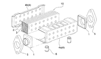
本発明の熱交換器は、アルミニウム製のEGRクーラまたは排熱回収に最適なものである。一例として図6に示す如く、インナーフィン3を内装した複数の偏平チューブ2が並列されてコア10を構成し、そのコア10の外周がケーシング本体4aとケーシング蓋4bとからなるケーシング4で被嵌され、その長手方向の両端部に一対の排ガスタンク1が嵌着し、その排ガスタンク1にそれぞれフランジ5が取り付けられる。
Next, embodiments of the present invention will be described with reference to the drawings.
The heat exchanger of the present invention is optimal for an aluminum EGR cooler or exhaust heat recovery. As an example, as shown in FIG. 6, a plurality of
このコア10を構成する偏平チューブ2は、図3に示す如く溝型に形成された一対のアルミニウム材からなり、その両端部の厚み方向に拡開部2dが形成されている。各溝型アルミニウム材の外周には多数のディンプル2eが突設され、その高さが拡開部2dの拡開高さに整合する。各偏平チューブ2内には、一例として図4に示すオフセット型のインナーフィン3が挿入される。なお、このオフセットフィンの代わりにストレートフィンあるいはウェーブフィンを挿入してもよい。図4に示すオフセットフィンを用いる場合には、その高さhは好ましくは1mm〜5mmとし、フィンピッチLはその高さhの0.5倍〜0.6倍、横ピッチQは高さhの0.5倍〜0.8倍である。また、偏平チューブ2の高さと幅の比は5〜50が好ましい。
The
このようなインナーフィン3を有する偏平チューブ2は図6に示す如く、その両端部のみが多数隙間なく積層されて、ヘッダープレートを不要とした、コア10を構成する。そして、そのコア10の両端に一対の排ガスタンク1が被嵌され、それらの外周をケーシング4が被嵌する。それと共に、一対の冷却水パイプ6がケーシング本体4aの開口に嵌着し、各排ガスタンク1にフランジ5が被着される。そして、全体が炉内に挿入され一体的にろう付け固定されるものである。そして、排ガスタンク1および偏平チューブ2内に図8の如く排ガス7が流通し、偏平チューブ2の外面側に冷却水8が流通して熱交換が行われるものである。その熱交換により、偏平チューブ2内部には腐食性凝縮水が生成される。
As shown in FIG. 6, the
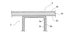
ここにおいて、本発明の特徴とするところは、その腐食性凝縮水に耐えうるアルミニウム製熱交換器の提供である。図1は偏平チューブ2およびインナーフィン3のろう付け前の状態を示す要部拡大図であり、図2はそのろう付け後の要部拡大図である。本発明の熱交換器は、腐食性のある凝縮水が接する側をすべてAl−Si−Zn系合金で被覆するものである。またチューブの芯材としてはAl−Mn−Cu系あるいはAl−Mn系合金を用いるものである。すなわち偏平チューブ2の芯材2aは、Al−Mn−Cu系で、インナーフィン3の芯材3aは、Al−Mn−Zn系あるいはAl−Mn系合金とする。そして偏平チューブ2、インナーフィン3のろう材2b、2c、3b、3cは、Al−Si−Zn系合金をクラッドしたブレージングシートを用いる。なお、偏平チューブ2の芯材2aの外面側にもろう材2bを用いている。これは偏平チューブ2を積層したとき、隣接する偏平チューブ2どうしを接合するものである。
Here, the feature of the present invention is to provide an aluminum heat exchanger that can withstand the corrosive condensed water. FIG. 1 is an enlarged view of a main part showing a state before the
〔実験例〕
本発明では各種実験の結果、偏平チューブ2の内面側のろう材2cとインナーフィン3のろう材3b、3cにおけるZnの成分範囲は、異なる方が好ましいことをつきとめた。 一例として、アルミニウム製(アルミニウム合金、以下同じ)の偏平チューブ2のろう材2cのZn量を全体の1.5〜3.0重量%(以下全て重量%)としたとき、アルミニウム製インナーフィン3のろう材3b、3cのZn量は1.0〜2.0%とすることが最も好ましい。
[Experimental example]
In the present invention, as a result of various experiments, it was found that the Zn component ranges in the
次に偏平チューブ2のろう材2cのZn量を1.5〜3.5%としたときには、インナーフィン3のろう材3b、3cのZn量は1.0〜1.5%である。
また、偏平チューブ2のろう材2cのZn量を1.5〜2.5%としたときには、インナーフィン3のろう材3b、3cは1.0〜2.5%が好ましい。このようなブレージングシートを用いたインナーフィン3内装の偏平チューブ2を積層してコア10を構成すると共に、排ガスタンク1も、偏平チューブ2同様にその内外面に同一のろう材を被覆したブレージングシートを用いて、そのコア10の両端に嵌着する。また、ケーシング4は少なくとも内面側にろう材が被覆されたものを用いる。そして、フランジ5、冷却水パイプ6を取付け、全体を高温の炉内に挿入し、各部品間を一体的にろう付け固定する。すると、偏平チューブ2の内面側およびインナーフィン3の両面側全体にろう材が被覆される。このように、排ガス7が流通し、その凝縮水が発生する内面側にろう材が被覆されると、その各ろう材のZn成分量により腐食しにくくなることが下記実験により明らかとなった。
Next, when the amount of Zn in the
When the Zn content of the
先ず偏平チューブ2の芯材2aとしてAl−Mn−Cu系合金を用いる。具体的にはAl−1%Mn−0.5%Cuである。そのろう材2b、2cとしてAl−Si−Zn系合金を用いる。具体的にはSiが7.5%、Znを0.5〜4.0%、残部をAlとする。
次にインナーフィン3はその芯材3aとして、Al−Mn−Zn系合金あるいは、Al−Mn−Si−Zn系合金を用いる。具体的にはMnが1%、Znが1%、残部Alである。そして、インナーフィン3のろう材3b、3cとして、Al−Si−Zn系を用い、Siを7.5%、Znを0.5〜3.0%、残部Alとする。
First, an Al—Mn—Cu alloy is used as the
Next, the
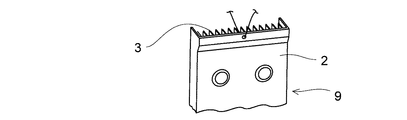
そして、図4におけるインナーフィン3を、図3の如く、偏平チューブ2内に挿入する。そして、炉内でろう付け後、偏平チューブ2の厚み方向に、中心線上で二分割し、図5に示す試験体9を作る。
そして、ガソリンエンジンまたはディーゼルエンジンの燃焼ガスから生じる凝縮液の相当液をあらかじめ用意する。この模擬的な凝縮水成分は、水にSO4 2-が5000ppm、CH3COO-が2500ppm、HCOO-が5000ppm、NO3 -が500ppm、Cl-が50ppmである。
そして、試験条件として、模擬凝縮水に2分間試験体9を浸漬し、次いで280℃で5分間高温乾燥させ、次に空冷を10分間行う。これを1サイクルとして100サイクル繰返し行う。
Then, the
Then, an equivalent liquid of the condensate generated from the combustion gas of the gasoline engine or the diesel engine is prepared in advance. This simulated condensed water component has SO 4 2− at 5000 ppm, CH 3 COO − at 2500 ppm, HCOO − at 5000 ppm, NO 3 − at 500 ppm, and Cl − at 50 ppm in water.
Then, as test conditions, the
そして、各部を切断し、その侵食深さを顕微鏡により判定した。
その結果が表1である。この表において、白丸は各部とも侵食深さが極めて小さいものであり、ろう材による模擬凝縮水による耐食性が証明された範囲である。黒丸はチューブの侵食深さが大で侵食形態は孔食状である。黒三角はフィンの腐食量が多いあるいは、フィンに粒界腐食が発生している。黒四角はろうフィレット部の腐食が大である。あるいは共晶部が選択腐食している。
And each part was cut | disconnected and the erosion depth was determined with the microscope.
The results are shown in Table 1. In this table, each white circle has a very small erosion depth in each part, and is a range in which corrosion resistance by simulated condensed water by brazing material is proved. The black circle has a large erosion depth of the tube, and the erosion form is pitting corrosion. In the black triangle, the amount of corrosion of the fins is large, or intergranular corrosion occurs on the fins. The black square has a large corrosion of the wax fillet. Alternatively, the eutectic part is selectively corroded.

●・・チューブ腐食深さが大で、腐食形態は孔食状
▲・・フィン腐食量が多い。あるいは、粒界腐食状形態が発生
■・・ろう付フィレット部の腐食が大。あるいは、共晶部が選択腐食発生
● ・ ・ Tube corrosion depth is large and the corrosion form is pitting corrosion
▲ ・ ・ The amount of fin corrosion is large. Or grain boundary corrosion-like morphology occurs
■ ・ ・ Corrosion of braze fillet is large. Alternatively, selective corrosion occurs in the eutectic part
この結果から、クラッドチューブのろう材のZn量が1.5%〜3.0%の条件ではクラッドフィン材のろう材のZn量が1.0〜2.0%の範囲でフィンおよびチューブ各部とも腐食深さが小さいことが分かる。
またクラッドチューブのろう材のZn量が1.5〜3.5%の範囲ではクラッドフィンのろう材のZn量が1.0〜1.5%の範囲で各部とも侵食深さが小さいことが分かる。
さらにクラッドチューブのろう材のZn量が1.5〜2.5%の範囲では、クラッドフィン材のろう材のZn量が1.0〜2.5%までの範囲で各部とも侵食深さが小さいことが分かる。
次に、上記表1では、チューブ芯材としてAl−Mn−Cu系を用いたが、それに代えてAl−Mn−Si−Cuでも同様の実験を行ったが、同様の実験結果が得られた。また、ろう材としてAl−7.5%Si−ZnにおけるSi量を5.0〜10.0%に変化させても、同様の結果を得られた。
From this result, it was found that the amount of Zn in the brazing material of the clad fin material was 1.0 to 2.0% under the condition that the amount of Zn in the brazing material of the clad tube was 1.5% to 3.0%. It can be seen that the corrosion depth is small.
In addition, when the Zn content of the brazing material of the clad tube is in the range of 1.5 to 3.5%, the erosion depth is small in each part when the Zn content of the brazing material of the clad fin is in the range of 1.0 to 1.5%. I understand.
Furthermore, when the Zn content of the brazing material of the clad tube is in the range of 1.5 to 2.5%, the erosion depth of each part is within the range of the Zn content of the brazing material of the clad fin material from 1.0 to 2.5%. I understand that it is small.
Next, in Table 1 above, Al-Mn-Cu system was used as the tube core material, but similar experiments were performed using Al-Mn-Si-Cu instead, but similar experimental results were obtained. . Moreover, even if the amount of Si in Al-7.5% Si-Zn as a brazing material was changed to 5.0 to 10.0%, similar results were obtained.
〔比較実験〕
チューブ材のみにクラッドろう材を用い、フィン材にはろう材を被覆せず(ベア材)、そのフィンの芯材のみとし、それ自体にZnを有するアルミニウム合金を用いた。クラッドチューブ材としては、表1の場合と同様に、その芯材にAl−Mn−Cu合金を用いクラッドろう材としてAl−7.5%Si−Znを用い、そのZnを1.0〜4.0%とした。そして、フィン材の芯材成分は表2の如く用い、そのZn量を1.0〜1.5%とする。
その結果は表2に示す通りである。
[Comparison experiment]
A clad brazing material was used only for the tube material, a brazing material was not coated on the fin material (bare material), only the core material of the fin, and an aluminum alloy containing Zn itself. As in the case of Table 1, as the clad tube material, an Al-Mn-Cu alloy is used as the core material, Al-7.5% Si-Zn is used as the clad brazing material, and the Zn is changed to 1.0-4. 0.0%. The core material component of the fin material is used as shown in Table 2, and the Zn content is 1.0 to 1.5%.
The results are as shown in Table 2.
●・・チューブ腐食深さが大で、腐食形態は孔食状
▲・・フィン腐食量が多い。あるいは、粒界腐食状形態が発生
■・・ろう付フィレット部の腐食が大。あるいは、共晶部が選択腐食発生
● ・ ・ Tube corrosion depth is large and the corrosion form is pitting corrosion
▲ ・ ・ The amount of fin corrosion is large. Or grain boundary corrosion-like morphology occurs
■ ・ ・ Corrosion of braze fillet is large. Alternatively, selective corrosion occurs in the eutectic part
フィン材にろう材を被覆しなかった場合には、芯材にZnを有するものを用いても、フィンの腐食が大きく、かついずれもフィン材に粒界腐食が発生することが分かった。これはそのフィン腐食により熱交換性能を永続的に維持することができないものである。 When the brazing material was not coated on the fin material, it was found that even when the core material containing Zn was used, the fin corrosion was large and intergranular corrosion occurred in the fin material. This is because the heat exchange performance cannot be maintained permanently due to the fin corrosion.
1 排ガスタンク
2 偏平チューブ
2a 芯材
2b ろう材
2c ろう材
2d 拡開部
2e ディンプル
1
2a Core material
2b Brazing material
2c Brazing material
2d expansion part
2e dimple
3 インナーフィン
3a 芯材
3b ろう材
3c ろう材
4 ケーシング
4a ケーシング本体
4b ケーシング蓋
3 Inner fin
3a Core material
3b brazing material
4a Casing body
4b Casing lid
5 フランジ
6 冷却水パイプ
7 排ガス
8 冷却水
9 試験体
10 コア
5
10 core
Claims (4)
それぞれアルミニウム製で、前記偏平チューブ(2) 材及び排ガスタンク(1)の少なくとも内面側全面にZnを1.5〜3.0%含むろう材が被覆されると共に、インナーフィン(3) 材の両面の全面にZnを1.0〜2.0%を含むろう材が被覆された各部品を組み立てる工程と、その組み立体を炉内に挿入して、前記ろう材を溶融し、次いでそれを固化して、各部品間を一体にろう付け固定すると共に、その偏平チューブ(2) の内面全体およびインナーフィン(3) の全体及び排ガスタンク(1)の内面全体を固化した前記ろう材で被覆する工程とを有することを特徴とするアルミニウム製排ガス用熱交換器の製造方法。 A plurality of flat tubes (2) whose ends communicate with the exhaust gas tank (1) are juxtaposed, and inner fins (3) are interposed inside the flat tubes (2), and the flat tubes (2) In the method of manufacturing a heat exchanger for exhaust gas in which corrosive condensed water is generated,
Each made of aluminum, the brazing material containing 1.5 to 3.0% Zn is coated on at least the entire inner surface side of the flat tube (2) material and the exhaust gas tank (1) , and the entire surface of both surfaces of the inner fin (3) material. A process of assembling each part coated with a brazing material containing 1.0 to 2.0% of Zn, and inserting the assembled solid body into a furnace to melt the brazing material, and then solidifying it, between each part And brazing and fixing together, and covering the entire inner surface of the flat tube (2), the entire inner fin (3), and the entire inner surface of the exhaust gas tank (1) with the solidified brazing material. A method for producing a heat exchanger for exhaust gas made of aluminum.
それぞれアルミニウム製で、前記偏平チューブ(2) 材の内面側にZnを1.5〜3.5%含むろう材が被覆されると共に、インナーフィン(3) 材の両面にZnを1.0〜1.5%を含むろう材が被覆された各部品を組み立てる工程と、その組み立体を炉内に挿入して、前記ろう材を溶融し、次いでそれを固化して、各部品間を一体にろう付け固定すると共に、その偏平チューブ(2) の内面全体およびインナーフィン(3) の全体を固化した前記ろう材で被覆する工程とを有することを特徴とするアルミニウム製排ガス用熱交換器の製造方法。 A plurality of flat tubes (2) whose ends communicated with the exhaust gas tank (1) are juxtaposed, and inner fins (3) are inserted inside the flat tubes (2). In the method of manufacturing a heat exchanger for exhaust gas in which corrosive condensed water is generated,
Each brazing material made of aluminum and coated with a brazing material containing 1.5 to 3.5% Zn on the inner surface side of the flat tube (2) material, and containing 1.0 to 1.5% Zn on both sides of the inner fin (3) material A step of assembling each of the parts coated with, and inserting the assembly into the furnace to melt the brazing material, then solidifying it, brazing and fixing the parts together, and flattening the parts And a step of coating the entire inner surface of the tube (2) and the entire inner fin (3) with the solidified brazing material.
それぞれアルミニウム製で、前記偏平チューブ(2) 材の内面側にZnを1.5〜2.5%含むろう材が被覆されると共に、インナーフィン(3) 材の両面にZnを1.0〜2.5%を含むろう材が被覆された各部品を組み立てる工程と、その組み立体を炉内に挿入して、前記ろう材を溶融し、次いでそれを固化して、各部品間を一体にろう付け固定すると共に、その偏平チューブ(2) の内面全体およびインナーフィン(3) の全体を固化した前記ろう材で被覆する工程とを有することを特徴とするアルミニウム製排ガス用熱交換器の製造方法。 A plurality of flat tubes (2) whose ends communicated with the exhaust gas tank (1) are juxtaposed, and inner fins (3) are inserted inside the flat tubes (2). In the method of manufacturing a heat exchanger for exhaust gas in which corrosive condensed water is generated,
Each brazing material made of aluminum and coated with a brazing material containing 1.5 to 2.5% Zn on the inner surface side of the flat tube (2) material, and containing 1.0 to 2.5% Zn on both sides of the inner fin (3) material A step of assembling each of the parts coated with, and inserting the assembly into the furnace to melt the brazing material, then solidifying it, brazing and fixing the parts together, and flattening the parts And a step of coating the entire inner surface of the tube (2) and the entire inner fin (3) with the solidified brazing material.
Priority Applications (1)
| Application Number | Priority Date | Filing Date | Title |
|---|---|---|---|
| JP2009099919A JP5468809B2 (en) | 2009-04-16 | 2009-04-16 | Method for producing heat exchanger for exhaust gas made of aluminum and its heat exchanger |
Applications Claiming Priority (1)
| Application Number | Priority Date | Filing Date | Title |
|---|---|---|---|
| JP2009099919A JP5468809B2 (en) | 2009-04-16 | 2009-04-16 | Method for producing heat exchanger for exhaust gas made of aluminum and its heat exchanger |
Publications (2)
| Publication Number | Publication Date |
|---|---|
| JP2010249426A JP2010249426A (en) | 2010-11-04 |
| JP5468809B2 true JP5468809B2 (en) | 2014-04-09 |
Family
ID=43311965
Family Applications (1)
| Application Number | Title | Priority Date | Filing Date |
|---|---|---|---|
| JP2009099919A Active JP5468809B2 (en) | 2009-04-16 | 2009-04-16 | Method for producing heat exchanger for exhaust gas made of aluminum and its heat exchanger |
Country Status (1)
| Country | Link |
|---|---|
| JP (1) | JP5468809B2 (en) |
Cited By (3)
| Publication number | Priority date | Publication date | Assignee | Title |
|---|---|---|---|---|
| US9671170B2 (en) | 2012-11-06 | 2017-06-06 | Borgwarner Emissions Systems Spain, S.L.U. | Heat exchange device for exchanging heat between fluids |
| US10113515B1 (en) | 2017-04-28 | 2018-10-30 | Hyundai Motor Company | Water cooled EGR cooler |
| US10378487B2 (en) | 2016-09-09 | 2019-08-13 | Hyundai Motor Company | Water-cooled exhaust gas recirculation cooler |
Families Citing this family (7)
| Publication number | Priority date | Publication date | Assignee | Title |
|---|---|---|---|---|
| JP5533715B2 (en) | 2010-04-09 | 2014-06-25 | 株式会社デンソー | Exhaust heat exchanger |
| FR2967765B1 (en) * | 2010-11-19 | 2015-03-06 | Valeo Systemes Thermiques | ARMABLE COMPONENT AND HEAT EXCHANGER HAVING THE SAME |
| JP5585558B2 (en) * | 2011-09-24 | 2014-09-10 | 株式会社デンソー | Exhaust heat exchanger |
| WO2013080611A1 (en) * | 2011-12-02 | 2013-06-06 | 古河スカイ株式会社 | Heat exchanger and method for manufacturing same |
| JP5668697B2 (en) * | 2012-01-23 | 2015-02-12 | トヨタ自動車株式会社 | Manufacturing method of heat exchanger |
| JP2014052086A (en) * | 2012-09-05 | 2014-03-20 | T Rad Co Ltd | Header-plate-less heat exchanger |
| KR101889441B1 (en) * | 2017-04-17 | 2018-08-20 | 주식회사 코렌스 | Aluminium alloy materials having improved corrosion resistance for gas tube of EGR cooler |
Family Cites Families (5)
| Publication number | Priority date | Publication date | Assignee | Title |
|---|---|---|---|---|
| JP2006009744A (en) * | 2004-06-29 | 2006-01-12 | Hino Motors Ltd | Egr cooler |
| JP4431579B2 (en) * | 2004-09-28 | 2010-03-17 | 株式会社ティラド | EGR cooler |
| JP4817879B2 (en) * | 2006-02-23 | 2011-11-16 | マルヤス工業株式会社 | Heat exchanger |
| JP4736847B2 (en) * | 2006-02-24 | 2011-07-27 | 株式会社デンソー | Heat exchanger and manufacturing method thereof |
| JP5192718B2 (en) * | 2007-04-10 | 2013-05-08 | 三菱アルミニウム株式会社 | Fin material and heat exchanger with excellent strength, sacrificial anode effect, and corrosion resistance |
-
2009
- 2009-04-16 JP JP2009099919A patent/JP5468809B2/en active Active
Cited By (3)
| Publication number | Priority date | Publication date | Assignee | Title |
|---|---|---|---|---|
| US9671170B2 (en) | 2012-11-06 | 2017-06-06 | Borgwarner Emissions Systems Spain, S.L.U. | Heat exchange device for exchanging heat between fluids |
| US10378487B2 (en) | 2016-09-09 | 2019-08-13 | Hyundai Motor Company | Water-cooled exhaust gas recirculation cooler |
| US10113515B1 (en) | 2017-04-28 | 2018-10-30 | Hyundai Motor Company | Water cooled EGR cooler |
Also Published As
| Publication number | Publication date |
|---|---|
| JP2010249426A (en) | 2010-11-04 |
Similar Documents
| Publication | Publication Date | Title |
|---|---|---|
| JP5468809B2 (en) | Method for producing heat exchanger for exhaust gas made of aluminum and its heat exchanger | |
| KR101922746B1 (en) | Alloys for a heat exchanger tube having an inner protective cladding and brazed disrupter | |
| US10006724B2 (en) | Multiply-clad brazing metal sheet | |
| EP1906127A2 (en) | Corrosion resistant bi-metal charge air cooler | |
| JP7485611B2 (en) | Multi-layer brazing sheet | |
| JP2008238223A (en) | Brazing method | |
| US20080078533A1 (en) | Corrosion resistant, alloy-coated charge air cooler | |
| JP6932102B2 (en) | Aluminum alloy heat exchanger for exhaust gas recirculation system | |
| JP2017044468A (en) | Brazable component and heat exchanger comprising the same | |
| GB2407054A (en) | Brazing method | |
| WO2008131001A1 (en) | Method of producing a corrosion resistant aluminum heat exchanger | |
| KR102463205B1 (en) | Egr cooler for vehicle | |
| JP2001174169A (en) | Heat exchanger | |
| JP5026306B2 (en) | Ni-Cu brazing material for heat exchanger | |
| JP2014202390A (en) | Heat exchanger manufacturing method and heat exchanger | |
| JP2012087342A (en) | Aluminum clad material for heat exchanger | |
| JP4270661B2 (en) | Multi-tube type EGR gas cooling device and manufacturing method thereof | |
| US20070227690A1 (en) | High density corrosive resistant gas to air heat exchanger | |
| JP6932101B2 (en) | Aluminum alloy heat exchanger for exhaust gas recirculation system | |
| JP3704178B2 (en) | Aluminum material for brazing and drone cup type heat exchanger using the material and excellent in corrosion resistance | |
| JP3876180B2 (en) | Aluminum alloy three-layer clad material | |
| JP2008064399A (en) | Heat exchanger | |
| JP3599126B2 (en) | Tubes used for brazing sheets and heat exchangers | |
| JP2000034532A (en) | Composite material for heat exchanger made of aluminum alloy | |
| KR20180028265A (en) | Aluminum plate and egr cooler using this |
Legal Events
| Date | Code | Title | Description |
|---|---|---|---|
| A621 | Written request for application examination |
Free format text: JAPANESE INTERMEDIATE CODE: A621 Effective date: 20120313 |
|
| A131 | Notification of reasons for refusal |
Free format text: JAPANESE INTERMEDIATE CODE: A131 Effective date: 20130507 |
|
| A521 | Written amendment |
Free format text: JAPANESE INTERMEDIATE CODE: A523 Effective date: 20130702 |
|
| TRDD | Decision of grant or rejection written | ||
| A01 | Written decision to grant a patent or to grant a registration (utility model) |
Free format text: JAPANESE INTERMEDIATE CODE: A01 Effective date: 20140121 |
|
| A61 | First payment of annual fees (during grant procedure) |
Free format text: JAPANESE INTERMEDIATE CODE: A61 Effective date: 20140130 |
|
| R150 | Certificate of patent or registration of utility model |
Ref document number: 5468809 Country of ref document: JP Free format text: JAPANESE INTERMEDIATE CODE: R150 Free format text: JAPANESE INTERMEDIATE CODE: R150 |