JP5465085B2 - Weight weighing device - Google Patents
Weight weighing device Download PDFInfo
- Publication number
- JP5465085B2 JP5465085B2 JP2010117446A JP2010117446A JP5465085B2 JP 5465085 B2 JP5465085 B2 JP 5465085B2 JP 2010117446 A JP2010117446 A JP 2010117446A JP 2010117446 A JP2010117446 A JP 2010117446A JP 5465085 B2 JP5465085 B2 JP 5465085B2
- Authority
- JP
- Japan
- Prior art keywords
- weight
- rotatably connected
- load cell
- pin
- load
- Prior art date
- Legal status (The legal status is an assumption and is not a legal conclusion. Google has not performed a legal analysis and makes no representation as to the accuracy of the status listed.)
- Active
Links
Images


Landscapes
- Refuse-Collection Vehicles (AREA)
Description
本発明は重量計量装置に関する。本発明の重量計量装置は、ダンプトラック、塵芥収集車、汚泥吸引車等のダンプ機構を持つ車両において過積載検出等のために積載物の重量計量を行う車載重量計量装置や、荷物集配場等における荷物の重量計量に適している。 The present invention relates to a weight weighing apparatus. The weight weighing device of the present invention is an on-vehicle weight weighing device for weighing a load to detect overloading in a vehicle having a dump mechanism such as a dump truck, a dust collection vehicle, a sludge suction vehicle, a luggage collection place, etc. Suitable for weighing of luggage in
従来、トラックや塵芥収集車等の車両に積載される積載物の重量を計測する装置として定置式のトラックスケールが知られている。しかし、トラックスケールは大掛かりな装置で、設備コストがかかるとともに、収集先での積込量測定や過積載防止のため、車両上で積載物の重量を計測したいという要望は強い。 Conventionally, a stationary truck scale is known as an apparatus for measuring the weight of a load loaded on a vehicle such as a truck or a garbage truck. However, the truck scale is a large-scale device, which requires high equipment costs, and there is a strong demand for measuring the weight of the load on the vehicle in order to measure the loading amount at the collection destination and prevent overloading.
また、大型ダンプトラックについては、国内ではいわゆるダンプ規制法により、過積載防止のために積載重量を自動的に計測する装置(自重計)を取り付けることが義務付けられている。 In addition, for large dump trucks, it is obliged in Japan to install a device (weighing scale) that automatically measures the loaded weight to prevent overloading according to the so-called dump regulation law.
このため、車両に搭載して積載重量を測定する車載重量計量装置が多種提案されている。 For this reason, various on-vehicle weight weighing devices that are mounted on vehicles and measure the loaded weight have been proposed.
ダンプ車両は通常油圧シリンダで積載台を傾斜させる構造を持っていて、積載台を傾斜した時、油圧シリンダに掛かる力を油圧センサで検出し過積載状態を検出する装置(自重計)が実用化されている(特許文献1)。しかしながら、この方式の自重計は積載台上での積載物の前後の偏りにより、計量値が大きく異なるという原理的な弱点があった。 A dump vehicle usually has a structure that tilts the loading platform with a hydraulic cylinder, and when the loading platform is tilted, a device that detects the overload status by detecting the force applied to the hydraulic cylinder with a hydraulic sensor is put into practical use. (Patent Document 1). However, this type of self-weight has the principle weak point that the measured values differ greatly due to the front-to-back bias of the load on the loading table.
ロードセルを3〜4点組み込んで荷箱全体をこれらで支持して、正確に計量する方式の車載重量計量装置が特許文献2〜4に示されている。これらの方式の場合、ロードセルを組み込むために車体フレームの一部を改造したり油圧シリンダを追加する必要があり、追加改造により車体重量が増え、最大積載量が減少する問題があった。また、部品点数増加により、高価になっていた。 Patent Documents 2 to 4 show an on-vehicle weight weighing device that incorporates 3 to 4 load cells and supports the entire packing box to accurately measure the load cell. In these systems, it is necessary to modify a part of the body frame or add a hydraulic cylinder in order to incorporate the load cell, and there has been a problem that the additional body modification increases the weight of the body and reduces the maximum load capacity. Moreover, it has become expensive due to an increase in the number of parts.
本発明は上記問題に鑑みてなされたもので、ロードセルの個数を最小化し、しかも計量物の重心位置の影響を受け難く、高精度で安全性や経済性に優れた重量計量装置を提供することを目的とする。 The present invention has been made in view of the above problems, and provides a weight weighing apparatus that minimizes the number of load cells and is not easily affected by the position of the center of gravity of the weighing object, and is highly accurate and excellent in safety and economy. With the goal.
本発明は、一端がヒンジ機構で基部に対して回転自在に支持されて計量物が積載される積載部と、前記積載部の前記一端から他端側に距離を隔てた位置に一端が回転自在に連結される一方、他端が前記基部に回転自在に連結された斜めに延びる支持部と、前記ヒンジ機構のピンを構成する軸状弾性体を備え、荷重検出方向が前記支持部の軸力の方向と直交するように前記基部に取り付けられたピン型ロードセルとを備える重量計量装置を提供する。 In the present invention, one end is freely rotatable at a position spaced from the one end to the other end side of the stacking portion by which one end is rotatably supported with respect to the base by a hinge mechanism and the weighing object is loaded. A support portion extending obliquely and having the other end rotatably connected to the base portion, and an axial elastic body constituting a pin of the hinge mechanism, the load detecting direction being the axial force of the support portion And a pin type load cell attached to the base so as to be orthogonal to the direction of the weight.
ヒンジ機構により片持ち梁状に基部に対して連結された積載部を斜めに延びる支持部で支持するトラス構造を採用し、このヒンジ機構に組み込んだピン型ロードセルで支持部の軸力の方向と直交する方向の荷重を測定する。これにより積載部上での計量物の重心位置の影響を低減して計量物の重量を高精度で計量できる。また、ロードセルの個数や付属装置の点数を従来よりも減らして安価な重量計量装置を実現できる。 A truss structure that supports the loading part connected to the base in the form of a cantilever by a hinge mechanism is supported by an obliquely extending support part, and the axial force direction of the support part is determined by a pin type load cell incorporated in this hinge mechanism. Measure the load in the orthogonal direction. Thereby, the influence of the gravity center position of the weighing object on the loading portion can be reduced, and the weight of the weighing object can be measured with high accuracy. In addition, an inexpensive weight measuring device can be realized by reducing the number of load cells and the number of attached devices.
本発明は、ダンプトラック、塵芥収集車、汚泥吸引車等のダンプ機構を持つ車両において過積載検出等のために積載物の重量計量を行う車載重量計量装置に適用できる。この場合、前記基部は車両の車体であり、前記積載部は、前記車体に搭載されて後部側が前記車体に対して前記ヒンジ機構によって前記車体に対して回転自在に連結され、前記ヒンジ機構を中心に傾動可能であり、前記支持部は一端が前記積載部に回転自在に連結されて他端が前記車体に対して回転自在に連結された伸縮可能なシリンダであり、前記ピン型ロードセルは、前記積載部が傾斜するように前記シリンダを伸張させたときの前記シリンダの推力の方向と直交する方向が前記荷重検出方向となるように前記車体に固定される。 INDUSTRIAL APPLICABILITY The present invention can be applied to an on-vehicle weight weighing device for weighing a load for overload detection or the like in a vehicle having a dump mechanism such as a dump truck, a dust collection vehicle, and a sludge suction vehicle. In this case, the base portion is a vehicle body, and the loading portion is mounted on the vehicle body, and a rear side is rotatably connected to the vehicle body by the hinge mechanism with respect to the vehicle body. The support part is a telescopic cylinder having one end rotatably connected to the loading part and the other end rotatably connected to the vehicle body, and the pin type load cell is The cylinder is fixed to the vehicle body so that a direction orthogonal to the direction of thrust of the cylinder when the cylinder is extended so that the loading portion is inclined is the load detection direction.
この構成により、ヒンジ機構にピン型ロードセルを組み込むことで車両の構造を大きく変更することなく容易に重量計量装置を搭載できる。また、ピン型ロードセルの軸状弾性体をヒンジ機構のピンとするので、重量計量装置を追加することによる重量増加や車高の変更も殆どなく、最大積載量を減らすこともない。さらに、非計量時や車両走行時は積載部は車体上に載置されるので車体強度の問題もなく安全に使用できる。 With this configuration, the weight weighing device can be easily mounted without greatly changing the structure of the vehicle by incorporating the pin type load cell into the hinge mechanism. Further, since the shaft-type elastic body of the pin type load cell is a pin of the hinge mechanism, there is almost no increase in weight or change in vehicle height due to the addition of a weight measuring device, and the maximum load capacity is not reduced. Furthermore, when the vehicle is not weighed or when the vehicle is running, the loading portion is placed on the vehicle body, so that it can be safely used without any problem of vehicle body strength.
本発明は、車載重量計量装置に限定されず、例えばトラック等の車両の荷物集配場に設置する定置式の重量計量装置にも適用できる。この場合、前記基部は、第1の床面部とこの第1の床面部よりも下方に位置する第2の床面部を有する段付きの床構造であり、前記積載部は一端が前記第1の床面部と同一高さとなるように前記ヒンジ機構によって前記床構造に対して回転自在に連結され、前記支持部は一端が前記積載部に回転自在に連結される一方、他端が前記第2の床面部に回転自在に連結された斜めに延びる固定長の支持部材であり、前記ピン型ロードセルは、前記支持部材の軸力の方向と直交する方向が前記荷重検出方向となるように前記床構造に固定される。 The present invention is not limited to the on-vehicle weight weighing device, and can also be applied to a stationary weight weighing device installed in a luggage collection area of a vehicle such as a truck. In this case, the base portion is a stepped floor structure having a first floor surface portion and a second floor surface portion positioned below the first floor surface portion, and one end of the loading portion is the first floor surface portion. The hinge mechanism is rotatably connected to the floor structure by the hinge mechanism so as to have the same height as the floor surface portion, and one end of the support portion is rotatably connected to the stacking portion, while the other end is the second portion. The pin-type load cell is a fixed-length support member that is obliquely extended and is rotatably connected to a floor surface portion, and the floor structure is configured such that a direction orthogonal to the axial force direction of the support member is the load detection direction. Fixed to.
本発明の重量計量装置によれば、ロードセルの個数を最小化しつつ、計量物の重心位置の影響を低減した高精度での重量計量が可能であり、安全性や経済性にも優れている。しかも、車載重量計量装置の場合、構造を大幅に変更することなくダンプ機構を持った車両に容易に組み込むことでき、車体重量の増加や車高の変更も殆どない。 According to the weight weighing device of the present invention, it is possible to perform weight weighing with high accuracy while minimizing the number of load cells and reducing the influence of the position of the center of gravity of the weighing object, and it is excellent in safety and economy. In addition, in the case of the on-vehicle weight weighing device, it can be easily incorporated into a vehicle having a dump mechanism without significantly changing the structure, and there is almost no increase in vehicle body weight or change in vehicle height.
まず、図1から図4を参照し、本発明に係る重量計量装置の基本的な構造と計量原理とを説明する。 First, with reference to FIG. 1 to FIG. 4, the basic structure and weighing principle of the weight weighing device according to the present invention will be described.
図1を参照すると、本発明の重量計量装置の基本的な構造としては、概ね水平に延びる積載台Aと、積載台Aを支持する斜めに傾いたロッド(傾斜ロッド)BCとを備える。積載台Aの一端Oは基部1の側壁部1aに対してヒンジ2Aで回転自在に支持されている。傾斜ロッドBCの先端Bは、ヒンジ2A(点O)から水平距離Lだけ離れた位置で積載台Aに対してヒンジ2Bで回転自在に連結されている。図1では、傾斜ロッドBCは積載台Aから図において右斜め下向き(積載台Aの先端側から基端側)に延びている。傾斜ロッドBCの他端Cは、ヒンジ2Cで基部1の底壁部1bに対して回転自在に連結されている。つまり、積載台A、傾斜ロッドBC、及び基部1が一種のトラス構造を構成している。傾斜ロッドBCは、固定長のロッドでもよいし、例えば油圧シリンダのような可変長の機構を備えるものでもよい。
Referring to FIG. 1, the basic structure of the weight weighing device of the present invention includes a loading table A that extends substantially horizontally and a slanting rod (tilting rod) BC that supports the loading table A. One end O of the loading table A is rotatably supported by a hinge 2 </ b> A with respect to the
傾斜ロッドBCの水平方向に対する傾き角をθ、傾斜ロッドBCの軸力(油圧ロッドの場合には推力)をP、積載台A上に載置された重量Wの計量物3の重心のヒンジ2A(点O)からの水平距離をaとして、モーメント及び力の釣合を考える。なお、図1に示すように、水平方向をX軸、鉛直方向をY軸とし、ヒンジ2A(点O)を原点とするX−Y座標系を設定する。また、ヒンジ2Aのピンを介して積載台Aに作用する反力RのX方向、Y方向成分をそれぞれRx,Ryとする。なお、理解を容易にするために、図1ではヒンジ2A(点O)と傾斜ロッドBの先端Bの高さ(Y方向の位置)を同一としている。
The inclination angle of the inclined rod BC with respect to the horizontal direction is θ, the axial force of the inclined rod BC (thrust in the case of a hydraulic rod) is P, and the
O点まわりのモーメントの釣合より、以下の式(1)が得られる。 From the balance of moments around the point O, the following equation (1) is obtained.

また、積載台Aに作用する力の釣合より、以下の式(2),(3)が得られる。 Further, from the balance of forces acting on the loading platform A, the following equations (2) and (3) are obtained.
ここで、X−Y座標系を角度αだけ回転させたs−t座標系においてs方向成分をRs、t方向成分をRtとする。反力の成分Rx,Ryをs−t座標系に座標変換すると、以下の式(4),(5)が得られる。 Here, in the st coordinate system obtained by rotating the XY coordinate system by the angle α, the s direction component is R s and the t direction component is R t . When the reaction force components R x and R y are coordinate-converted into the st coordinate system, the following equations (4) and (5) are obtained.
式(4),(5)よりα=θの場合、以下の式(6),(7)が得られる。 From the equations (4) and (5), when α = θ, the following equations (6) and (7) are obtained.
従って、計量物3の重量Wについて以下の式(8)が成立する。
Therefore, the following formula (8) is established for the weight W of the weighing
次に、図2に示すように、傾斜ロッドBCの長さが延びて(油圧シリンダの場合にはロッドが押し出され)、積載台Aをヒンジ2A(点O)を回転中心として角度βだけ回転させた場合(積載台Aを押し上げて支持した場合)を考える。
Next, as shown in FIG. 2, the length of the inclined rod BC is extended (in the case of a hydraulic cylinder, the rod is pushed out), and the loading platform A is rotated by an angle β around the
幾何学関係の変化により、θ→θ’、P→P’Rx→Rx’、Ry→Ry’になるとする。L→Lcosβ、a→a・cosβになることを考慮して、前述の式(1)〜(8)の変数を置換すると式(1)〜(8)と同様に以下の式(1’)〜(8’)が成り立つ。
It is assumed that θ → θ ′, P → P′R x → R x ′, and R y → R y ′ due to changes in the geometric relationship. Considering that L → Lcos β and a → a · cosβ, when the variables of the above-mentioned formulas (1) to (8) are replaced, the following formula (1 ′ ) To (8 ′).
まず、O点まわりのモーメントの釣合より以下の式(1’)が得られ、積載台Aに作用する力の釣合から以下の式(2’),(3’)が得られる。 First, the following equation (1 ') is obtained from the balance of moments around the point O, and the following equations (2') and (3 ') are obtained from the balance of forces acting on the loading platform A.
X−Y座標を角度αだけ回転させたs−t座標系においてs方向成分をRs'、t方向成分をRt’とし、Rx’,Ry’を座標変換すると、以下の式(4’),(5’)が得られる。 In the s coordinate system in which the XY coordinate is rotated by an angle α, the s direction component is R s ′, the t direction component is R t ′, and R x ′ and R y ′ are coordinate-transformed, the following formula ( 4 ') and (5') are obtained.
式(4’),(5’)よりα=θ'の場合、以下の式(6’),(7’)が得られる。 From the equations (4 ′) and (5 ′), when α = θ ′, the following equations (6 ′) and (7 ′) are obtained.
従って、計量物3の重量Wについて以下の式(8’)が成立する。
Therefore, the following formula (8 ′) is established for the weight W of the weighing
図3に示すように、傾斜ロッドBCが図1及び図2の場合とは反転した向き、すなわち積載台Aから図において左斜め下向き(積載台Aの基端側から先端側)に延びている場合にも、式(1)〜(8)と式(1’)〜(8’)が成り立つ。 As shown in FIG. 3, the inclined rod BC extends in the direction reverse to that in the case of FIGS. 1 and 2, that is, from the loading table A to the left diagonally downward (from the base end side to the front end side of the loading table A). Even in this case, the expressions (1) to (8) and the expressions (1 ′) to (8 ′) hold.
また、図4に示すように、傾斜ロッドBCに代えてリフトアーム4とテンションリンク5を持つリンク機構BB’Cを設けた場合(符号6は駆動用の油圧シリンダ)も、ヒンジ2Bのピンを介して積載台Aに働く推力Pの方向が水平となす角度をθとすると、式(1)〜(8)と式(1’)〜(8’)が成り立つ。
As shown in FIG. 4, when a link mechanism BB′C having a lift arm 4 and a
計量物3の重心位置aは、計量物3の積載台A上での位置や計量物3自体の密度分布の偏り等によって変化する。式(1)〜(6),式(1’)〜(6’)は、式中に重心位置aを変数として含むため計量物3の重心位置aにより値が変化する。一方、式(7),(7’)のRt,Rt’は、重心位置aを含まないため計量物3の重心位置aが変化しても原理的には値が変化しない。そして、式(8),(8’)のように、Rt,Rt’と角度θ,θ’のみから計量物3の重量Wを算出できる。
The center-of-gravity position a of the weighing
ここでRt’,Rs’はヒンジ2Aのピンを介して積載台Aに作用する反力であるが、ヒンジ2AのピンにはこれらのRt,Rt’と大きさが等しく向きが逆の力(荷重)が作用する。これらの荷重をFt’,Fs’とすると、以下の式(9),(10)の関係がある。
Here, R t ′ and R s ′ are reaction forces acting on the loading platform A via the pins of the
以上より、傾斜ロッドBCの傾きをある角度θ’に保持した状態で積載台Aの一端Oのヒンジ2Aのピンに作用する荷重Ft’を測定すれば、測定した荷重Ft’と設定した角度θ’とから式(9),(8)’により計量物3の荷重Wを算出できる。つまり、ヒンジ2Aのピンに作用する荷重Ft’,Fs’のうち積載台Aにより傾斜ロッドBCの軸力Pと直交する方向の荷重Ft’を測定することで、積載台A上での計量物3の重心位置aの影響を受けることなく計量物3の荷重Wの計量が可能となる。そして、積載台Aの一端Oのヒンジ2Aのピンに作用する荷重Ft’は、このヒンジ2Aにピン型ロードセルを組み込むことで測定できる。ピン型ロードセル自体は当業者に知られており、例えば特許文献3に開示されている。
As described above, if the load F t ′ acting on the pin of the
(第1実施形態)
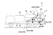
図5から図7に示すダンプ排出機能を有する汚泥吸引車11は、過積載検出等のために本発明の実施形態に係る車載重量計量装置12を備える。この汚泥吸引車11はシャシー13上に固定されたサブフレーム14上に吸引/集塵装置15で吸引した汚泥を溜めるためのタンク16を備える。タンク16は後方の左右2箇所がヒンジ17A,17Bによってサブフレーム14に対して回転自在に連結されている。後に詳述するように、これらのヒンジ17A,17Bにピン型ロードセル18が組み込まれている。また、ヒンジ17A,17Bよりも前方側にはタンク16を傾斜させるためのダンプシリンダ19A,19Bが左右に配置されている。個々のダンプシリンダ19A,19Bは、ロッドの先端である上端がタンク16の側面にピン結合により回転自在に連結される一方、下端はヒンジ21A,21Bによってサブフレーム14に対して回転自在に連結されている。排出シリンダ22A,22Bで開閉される排出扉23がタンク16の最後部に設けられている。
(First embodiment)
A
図5に示すように、非排出時にはタンク16の底面はサブフレーム14上に載置され、タンク重量の大部分がサブフレーム14に作用する。一方、排出時には、ダンプシリンダ19A,19Bを作動させてヒンジ17A,17B回りにタンク16を後傾させ、同時に排出シリンダ22A,22Bにより排出扉23を開放してタンク16内の集積物を外部に排出する。ダンプシリンダ19A,19Bは通常油圧シリンダが使用され、油圧回路の切換弁を動作させてダンプシリンダ19A,19Bのヘッド側への圧油の給排を停止することにより、タンク16の傾動を任意の位置で停止させることができる。
As shown in FIG. 5, the bottom surface of the
本実施形態の車載重量計量装置12は、図3と同様のトラス構造を有する。具体的には、タンク16が図3の積載台Aに対応し、ヒンジ17A,17Bが図3のヒンジ2A(点O)に対応する。また、ダンプシリンダ19A,19Bが図3の傾斜ロッドBCに対応し、ダンプシリンダ19A,19Bのロッドの先端が図3の点B、ダンプシリンダ19A,19Bの基端が図3の点Cにそれぞれ対応する。従って、タンク16を傾斜させて底面をサブフレーム14から浮き上がらせた状態で、ダンプシリンダ19A,19Bの推力Pと直交する方向の荷重Ft’をヒンジ17A,17Bに組み込んだピン型ロードセル18で測定することで、タンク16内の集積物の重量W(図3における計量物3の重量Wに相当)を計量できる。
The on-vehicle
図8及び図9を参照すると、ヒンジ17A,17Bはそれぞれサブフレーム14に固定された一対の固定軸受25A,25Bを備える。ピン型ロードセル18の軸状弾性体26は全体として円柱状であり、その軸線γが車幅方向に水平に延びる姿勢で両端が固定軸受25A,25Bに支持されている。固定軸受25Aにねじ止めされた回転抜け止め27により固定軸受25A,25Bに対する軸状弾性体26抜け止めと、軸線γまわりの軸状弾性体26の角度位置の位置決めがなされている。また、軸状弾性体26の中央部にはタンク16の底面に固定された可動側軸受28が回転自在に連結されており、タンク16の荷重がピン型ロードセル18の中央部に負荷される構造である。図9において符号f1はピン型ロードセル18の中央部に可動側軸受28から作用する荷重を示し、符号f2はピン型ロードセル18の両端に固定軸受25A,25Bから作用する支点反力を示す。
Referring to FIGS. 8 and 9, the
図10A及び図10Bを併せて参照すると、ピン型ロードセル18の軸状弾性体26には、固定軸受25Aと可動側軸受28の間、及び固定軸受25Bと可動側軸受28の間の部分にそれぞれ軸線γと直交する方向に対向する断面円形の凹部29A〜29Dの対を設け、凹部29A,29Bとの間、及び凹部29C,29Dとの間にそれぞれ比較的薄厚の円板状として軸線γに対して直交する方向の断面積を減少させた起歪部31A,31Bを設けている。起歪部31A,31Bは可動側軸受28から作用する荷重により適切なせん断歪みが発生するような形状に設計されている。個々の起歪部31A,31Bの両面には歪みゲージ32A〜32Dが貼り付けられている。これらの歪みゲージ32A〜32Dでホイーストンブリッジ回路を構成して荷重に比例した電気信号が得られるようにしている。
Referring to FIGS. 10A and 10B together, the shaft-like
ピン型ロードセル18には、荷重Ft’とこれと直交する荷重Fs’が同時に作用する。荷重Fs’は重心位置aを変数として含み(式(6’),(10)参照)、重心位置aによって値が変化する。図1〜図4を参照して説明したように、荷重Ft’,Fs’のうちダンプシリンダ19A,19Bの推力Pと直交する方向の荷重Ft’を測定することで、タンク16内の集積物の重心位置aの影響を受けることなく重量Wの計量が可能となる。従って、ピン型ロードセル18は荷重Ft’のみを検出し、荷重Fs’に対する出力がゼロであることが好ましい。個々のヒンジ17A,17Bに組み込んだピン型ロードセル18は荷重Fs’に対する出力が最小となるように軸線γまわりの角度位置が設定されている。以下、この点について説明する。
A load F t ′ and a load F s ′ that is orthogonal to the load F t ′ act simultaneously on the pin
一般にロードセルは荷重方向によって出力が変化し、通常使用する荷重軸(荷重検出方向)が定められている。図10A,Bのピン型ロードセル18の場合、起歪部31A,31Bの断面形状の方向Dに対して、図においてO°の方向を荷重検出方向D’としている。図11に起歪部31A,31Bの方向Dに対する荷重検出方向D’の傾斜角度αに対する理論出力比(V/V0=cosα Vはある傾斜角度αのときの出力で、V0はα=0のときの出力)の変化を示す。理論出力比は起歪部31A,31Bの方向Dに対する荷重検出方向D’の傾斜角度αが0°のときに最大である。傾斜角度αの増加に伴って理論出力比が減少し、傾斜角度αが90°となると理論出力比は殆どゼロとなる。従って、ピン型ロードセル18の荷重検出方向D’(0°方向)がダンプシリンダ19A,19Bの推力Pと直交する方向(図3においてs−t座標系のt方向に相当する方向)となるようにピン型ロードセル18の軸状弾性体26をそれ自体の軸線γまわりに角度θ’だけ回転させた姿勢で設置することにより、重量Wの計量に必要な荷重Ft’のみを検出し、荷重Fs’に対する出力を殆どゼロにすることができる。
In general, the output of a load cell varies depending on the load direction, and a load axis (load detection direction) that is normally used is determined. In the case of the pin
非計量時にはダンプシリンダ19A,19Bのロッドは引き込み位置にあり、タンク16の底面はサブフレーム14上に載置されている。計量時には、ダンプシリンダ19A,19Bのロッドが突出動作して、タンク16はヒンジ17A,17Bまわりに回転することで傾斜する。タンク16は前方が予め定められた位置(例えば50mm〜150mm)程度まで持ち上げられ、タンク16の底面がサブフレーム14を離れる。この状態では、タンク16はダンプシリンダ19A,19Bと後方のヒンジ17A,17Bで支持される。計測時のタンク16を傾斜させる際のダンプシリンダ19A,19Bの傾斜角度θ’は一定値に設定される。一定の傾斜角度θ’でタンク16の傾動を停止するために、停止位置を示す目盛板を設けて目視し、それに基づいてダンプシリンダ19A,19Bの動作を手動で停止してもよい。また、近接スイッチを設けてタンク16が所定の傾斜角度θ’となるとダンプシリンダ19A,19Bを自動的に停止させる制御回路を設けてもよい。前述したようにヒンジ17A,17Bに組み込まれたピン型ロードセル18は荷重検出方向D’がダンプシリンダ19A,19Bの推力Pと直交する方向となるように、この傾斜角度θ’だけ軸線γまわりに軸状弾性体26を回転して取り付けている。
During non-weighing, the rods of the
計測時のピン型ロードセル18は荷重Ft’=Wcosθを検出するがこれを重量Wとして表示するように車載重量計量装置12の初回の調整時に指示計のキャリブレーション(スパン調整)を行う。通常、指示計のキャリブレーション(スパン調整)は分銅か重量が既知のものをタンク16に搭載して行う。タンク16が空の状態では、タンク16自体の重量がピン型ロードセル18に作用するが、この空状態の際の出力を差し引いて表示がゼロとなるように指示計を調整し、タンク16内の積載物の増分を重量値として表示するようにする。
The pin-
ピン型ロードセル18は荷重Ft’=Wcosθを検出するが、図11を参照して説明したようにダンプシリンダ19A,19Bの傾斜角度θ’が90°となるとFt’=0となるため、原理的に計量ができない。また、θ’=90°付近では荷重Ft’が小さくなるため計量精度が低下する、そのため傾斜角度θ’は75°未満(例えば20°)に設定される。
The pin
ダンプシリンダ19A,19Bの傾斜角度θ’は設計値から求め、これからピン型ロードセル19の軸線γまわりの回転角度を決定することができるが、実際は製作誤差や設置誤差があり、理論通りの特性が得られない場合がある。タンク16内の計量物の重心位置により重量測定値が変化しないか否かは、調整時に一定の重さの分銅等をタンク16内で位置を変えて載せてみることで確認できる。分銅を載せる位置の違いで計量値の差が大きい場合、式(5’)等から傾斜角度θ’の修正値を推定し、それに基づいてピン型ロードセル19の回転角度を調整することで、タンク16内の計量物の重心位置による重量測定値の変動を実用上問題のない程度に低減できる。
The inclination angle θ ′ of the
図12A及び図12Bは本実施形態の車載重量計量装置12で使用可能なピン型ロードセル18の他の例を示す。このピン型ロードセル18では円柱状の軸状弾性体26に図10A,Bと同様の凹部29A〜29Dに加えて両端面から軸線γの方向の延びる凹部33A,33Bを設けている。凹部29A〜29D,33A,33Bによって形成された起歪部31A,31Bの内側に歪みゲージ32A〜32Dが貼り付けられている。図13A及び図13Bもピン型ロードセル18の他の例を示す。このピン型ロードセル18では軸状弾性体26に両端面間を貫通する貫通孔34の内周壁に歪みゲージ32A〜32Dを貼り付けている。ピン型ロードセル18の軸状弾性体26には曲げモーメントが作用するが(図10A、図12A、及び図13Aの符号f1,f2参照)、荷重Ft’を高精度で測定するために曲げモーメントによる歪みを歪みゲージ32A〜32Dが検出しないことが好ましい。曲げモーメントは軸状弾性体26の外周で大きく軸線γ(中立軸)でゼロとなるので、歪みゲージ32A〜32Dが軸線γに近い位置にある程曲げモーメントの影響を受けにくい。図10A,B及び図12A,Bのピン型ロードセル18は図13A,Bと比較すると歪みゲージ32A〜32Dの貼り付け位置が軸状弾性体26の軸線γに近い位置にあるので、より高精度で荷重Ft’を測定できる。ただし、図13A,Bのピン型ロードセル18は単一の貫通孔34のみを軸状弾性体26に形成すればよい簡易な構成であるので、図10A,B及び図12A,Bと比較すると軸状弾性体26の加工が容易で安価に製作できる利点がある。
12A and 12B show another example of the pin
本実施形態の車載重量計量装置12は特に以下の点に特徴がある。タンク16内の計量の重心位置の影響を低減して計量物の重量Wを高精度で計量できる。前述のようにダンプシリンダの油圧から圧力計を使用して積載量を検知する従来の自重計は積荷の位置により計量値が大きく変化する欠点があったが、この問題が解消している。また、従来の自重計よりロードセルの個数や付属装置の点数が減らせ、安価な重量計量装置となっている。さらに、ヒンジ機構17A,17Bにピン型ロードセル18を組み込むことで車両の構造を大きく変更することなく容易に重量計量装置を搭載できる。さらに、ピン型ロードセル18の軸状弾性体26をヒンジ機構17A,17Bのピンとするので、車載重量計量装置11を追加することによる車体重量の増加や車高の変更も殆どなく、最大積載量を減らすこともない。さらにまた、非計量時や車両走行時はタンク16はサブフレーム14上に載置されるのでフレーム強度の問題もなく安全に使用できる。
The on-vehicle
本発明は、本実施形態のような汚泥吸引車に限定されず、ダンプトラック、塵芥収集車等のダンプ機構を持つ他の車両における車載重量計量装置にも適用できる。本実施形態ではタンク16の後部左右のヒンジ17A,17Bの両方にピン型ロードセル18を組み込んでいるが、積載物が液体等の密度が均一で左右の荷重分布がほぼ均等とみなすことができる場合や、概略重量から過積載を検知したい場合等であれば、左右のヒンジの一方にのみピン型ロードセルを組み込んでもよい。
The present invention is not limited to the sludge suction vehicle as in the present embodiment, but can also be applied to an on-vehicle weight weighing device in other vehicles having a dump mechanism such as a dump truck and a garbage truck. In this embodiment, the pin
(第2実施形態)
図14は本発明の第2実施形態に係る荷物集配場用の重量計量装置41を示す。この荷物集配場の床構造42は図示しない倉庫等へ通路として機能する床面42aとこの床面42aよりも下方に位置する床面42bを備える段付き構造を有する。床面42aの床面42bからの高さは床面42bに駐車されたトラック43の荷台43aと概ね同じ高さ位置となるように設定されている。床面42aの先端から張り出しデッキ45が延びており、この張り出しデッキ45を通って荷台43aへの荷物46の積み降ろしが実行される。張り出しデッキ45は一端がヒンジ17A’,17B’により床構造42(床面42a,42bの境目にある側壁42c)に回転自在に連結されている。また、張り出しデッキ45の他端には固定長の傾斜ロッド47の一端がピン結合により回転自在に連結されている。傾斜ロッド47は張り出しデッキ45から図において右斜め下へ延びて、他端がピン結合により床面42bに対して回転自在に連結されている。この重量計量装置41は図1と同様のトラス構造を有し、張り出しデッキ45が図1の積載台A、ヒンジ17A’,17B’が図1のヒンジ2A(点O)、傾斜ロッド47が図1の傾斜ロッドBCにそれぞれ対応する。
(Second Embodiment)
FIG. 14 shows a
ヒンジ17A’,17B’には第1実施形態のヒンジ17A,17Bと同様にピン型ロードセル18が組み込まれている(ヒンジ17A’,17B’のピンがピン型ロードセル18の軸状弾性体26である)。ピン型ロードセル18の荷重検出方向D’(0°方向)が傾斜ロッド47の軸力Pと直交する方向となるようにピン型ロードセル18の軸状弾性体26の姿勢を設定している(図7,8参照)。ピン型ロードセル18の出力から荷重Ft’が得られ、この荷重Ft’と傾斜ロッド47の傾斜角度θ’から式(9),(8)により荷物46の荷重Wを算出できる。
Pin
第2実施形態のその他構成及び作用は第1実施形態と同様である。 Other configurations and operations of the second embodiment are the same as those of the first embodiment.
1 基部
1a 側壁部
1b 底壁部
2A,2B,2C ヒンジ
3 計量物
4 リフトアーム
5 テンションリンク
6 油圧シリンダ
11 汚泥吸引車
12 車載重量計量装置
13 シャシー
14 サブフレーム
15 吸引/集塵装置
16 タンク
17A,17B ヒンジ
18 ピン型ロードセル
19A,19B ダンプシリンダ
21A,21B ヒンジ
22A,22B 排出シリンダ
23 排出扉
25A,25B 固定軸受
26 軸状弾性体
27 回転抜け止め
28 可動側軸受
29A,29B,29C,29D 凹部
31A,31B 起歪部
32A,32B,32C,32D 歪みゲージ
33A,33B 凹部
34 貫通孔
41 重量計量装置
42 床構造
42a,42b 床面
42c 側壁
43 トラック
43a 荷台
45 張り出しデッキ
46 荷物
47 傾斜ロッド
DESCRIPTION OF
Claims (3)
前記積載部の前記一端から他端側に距離を隔てた位置に一端が回転自在に連結される一方、他端が前記基部に回転自在に連結された斜めに延びる支持部と、
前記ヒンジ機構のピンを構成する軸状弾性体を備え、荷重検出方向が前記支持部の軸力の方向と直交するように前記基部に取り付けられたピン型ロードセルと
を備える重量計量装置。 A loading unit on which one end is rotatably supported with respect to the base by a hinge mechanism and a weighing object is loaded;
A support portion extending obliquely, one end of which is rotatably connected to a position spaced from the one end to the other end of the stacking portion, while the other end is rotatably connected to the base;
A weight weighing apparatus comprising: a pin-type load cell including a shaft-like elastic body constituting a pin of the hinge mechanism and attached to the base so that a load detection direction is orthogonal to a direction of the axial force of the support portion.
前記積載部は、前記車体に搭載されて後部側が前記車体に対して前記ヒンジ機構によって前記車体に対して回転自在に連結され、前記ヒンジ機構を中心に傾動可能であり、
前記支持部は一端が前記積載部に回転自在に連結されて他端が前記車体に対して回転自在に連結された伸縮可能なシリンダであり、
前記ピン型ロードセルは、前記積載部が傾斜するように前記シリンダを伸張させたときの前記シリンダの推力の方向と直交する方向が前記荷重検出方向となるように前記車体に固定されている、請求項1に記載の重量計量装置。 The base is a vehicle body;
The loading portion is mounted on the vehicle body, a rear side thereof is rotatably connected to the vehicle body by the hinge mechanism with respect to the vehicle body, and can tilt around the hinge mechanism.
The support part is an extendable cylinder having one end rotatably connected to the loading part and the other end rotatably connected to the vehicle body,
The pin-type load cell is fixed to the vehicle body such that a direction orthogonal to a direction of thrust of the cylinder when the cylinder is extended so that the loading portion is inclined is the load detection direction. Item 2. The weight weighing device according to Item 1.
前記積載部は一端が前記第1の床面部と同一高さとなるように前記ヒンジ機構によって前記床構造に対して回転自在に連結され、
前記支持部は一端が前記積載部に回転自在に連結される一方、他端が前記第2の床面部に回転自在に連結された斜めに延びる固定長の支持部材であり、
前記ピン型ロードセルは、前記支持部材の軸力の方向と直交する方向が前記荷重検出方向となるように前記床構造に固定されている、請求項1に記載の重量計量装置。 The base portion is a stepped floor structure having a first floor surface portion and a second floor surface portion located below the first floor surface portion,
The loading portion is rotatably connected to the floor structure by the hinge mechanism so that one end thereof is flush with the first floor surface portion,
The support part is a fixed-length support member extending obliquely, one end of which is rotatably connected to the stacking part, and the other end of which is rotatably connected to the second floor surface part.
The weight measuring apparatus according to claim 1, wherein the pin type load cell is fixed to the floor structure such that a direction orthogonal to a direction of an axial force of the support member is the load detection direction.
Priority Applications (2)
| Application Number | Priority Date | Filing Date | Title |
|---|---|---|---|
| JP2010117446A JP5465085B2 (en) | 2010-05-21 | 2010-05-21 | Weight weighing device |
| CN201110144302.2A CN102269618B (en) | 2010-05-21 | 2011-05-20 | Weighing device |
Applications Claiming Priority (1)
| Application Number | Priority Date | Filing Date | Title |
|---|---|---|---|
| JP2010117446A JP5465085B2 (en) | 2010-05-21 | 2010-05-21 | Weight weighing device |
Publications (3)
| Publication Number | Publication Date |
|---|---|
| JP2011242375A JP2011242375A (en) | 2011-12-01 |
| JP2011242375A5 JP2011242375A5 (en) | 2013-05-02 |
| JP5465085B2 true JP5465085B2 (en) | 2014-04-09 |
Family
ID=45051987
Family Applications (1)
| Application Number | Title | Priority Date | Filing Date |
|---|---|---|---|
| JP2010117446A Active JP5465085B2 (en) | 2010-05-21 | 2010-05-21 | Weight weighing device |
Country Status (2)
| Country | Link |
|---|---|
| JP (1) | JP5465085B2 (en) |
| CN (1) | CN102269618B (en) |
Families Citing this family (9)
| Publication number | Priority date | Publication date | Assignee | Title |
|---|---|---|---|---|
| JP6108687B2 (en) * | 2012-05-23 | 2017-04-05 | 株式会社Ihiスター | Weight measuring apparatus and control method of weight measuring apparatus |
| CN103063345B (en) * | 2012-12-19 | 2015-06-10 | 三一重工股份有限公司 | Method for detecting radial force stressed on shaft pin |
| CN103438965B (en) * | 2013-09-04 | 2016-02-10 | 山东胜油固井工程技术有限公司 | Hinge type storage tank Weighing device |
| JP6326394B2 (en) * | 2015-10-09 | 2018-05-16 | Kyb株式会社 | Mixer truck load weighing device |
| CN105403299B (en) * | 2015-12-21 | 2019-04-09 | 天津汇丰金属探测股份有限公司 | A kind of Balancer for fork trucks |
| CN106840339B (en) * | 2017-01-22 | 2019-06-11 | 浙江联运知慧科技有限公司 | A method of fortune vehicle rubbish dynamic weighing is received for environmental sanitation |
| CN106932064A (en) * | 2017-03-29 | 2017-07-07 | 徐州赫思曼电子有限公司 | A kind of self-discharging vehicle weighing device and its method of work |
| CN109990878A (en) * | 2019-03-01 | 2019-07-09 | 利康森隆(丹阳)智能机械有限公司 | A kind of semitrailer Onboard weighing device and installation method |
| CN116465752B (en) * | 2023-06-20 | 2023-08-25 | 河北济沧建设科技有限公司 | Multifunctional detection device for building materials |
Family Cites Families (16)
| Publication number | Priority date | Publication date | Assignee | Title |
|---|---|---|---|---|
| JPS5255562A (en) * | 1975-10-31 | 1977-05-07 | Komatsu Mfg Co Ltd | Apparatus for measuring weight of vessel loadage |
| CN1024218C (en) * | 1985-07-05 | 1994-04-13 | 勒鲁瓦·赫根布 | Devices that respond to the load measured on the vehicle |
| JPS6345510A (en) * | 1986-08-13 | 1988-02-26 | Tokyu Car Corp | Load detecting device |
| JP2711751B2 (en) * | 1990-07-11 | 1998-02-10 | 株式会社クボタ | Forklift truck |
| CN2114819U (en) * | 1992-03-17 | 1992-09-02 | 李界生 | Tank type powdery material metering device for transport vehicle |
| JP3518703B2 (en) * | 1995-04-25 | 2004-04-12 | 富士重工業株式会社 | Weighing method, weighing device and garbage truck equipped with weighing device |
| JP4028609B2 (en) * | 1996-09-24 | 2007-12-26 | 小平産業株式会社 | Device for measuring the weight of a load on a vehicle with an inclined platform |
| JP3794094B2 (en) * | 1997-03-12 | 2006-07-05 | 日産自動車株式会社 | Forklift stability test jig |
| JPH1151753A (en) * | 1997-08-06 | 1999-02-26 | Fuji Heavy Ind Ltd | Apparatus and method for detection of load |
| CN2450647Y (en) * | 2000-11-09 | 2001-09-26 | 张家港保税区中诚国际工贸有限公司 | Dynamic shaft pin type force cell |
| JP3684177B2 (en) * | 2001-08-01 | 2005-08-17 | 株式会社マツモト | Tank tank with measuring instrument |
| US7247803B2 (en) * | 2004-01-15 | 2007-07-24 | Komatsu Ltd. | Loaded weight measurement method and loaded weight measurement device for dump truck |
| JP4762688B2 (en) * | 2005-11-16 | 2011-08-31 | Jfeアドバンテック株式会社 | On-vehicle weight weighing device and vehicle equipped with the on-vehicle weight weighing device |
| JP2009101979A (en) * | 2007-10-01 | 2009-05-14 | Koji Futamura | Conveying vehicle capable of measuring weight of loaded object |
| CN201354031Y (en) * | 2009-01-23 | 2009-12-02 | 重庆大唐测控技术有限公司 | Dump truck weighing device |
| CN101571418B (en) * | 2009-06-11 | 2011-04-27 | 重庆大唐科技股份有限公司 | Weighing method of dynamic self-discharging car scales |
-
2010
- 2010-05-21 JP JP2010117446A patent/JP5465085B2/en active Active
-
2011
- 2011-05-20 CN CN201110144302.2A patent/CN102269618B/en not_active Expired - Fee Related
Also Published As
| Publication number | Publication date |
|---|---|
| JP2011242375A (en) | 2011-12-01 |
| CN102269618B (en) | 2014-03-12 |
| CN102269618A (en) | 2011-12-07 |
Similar Documents
| Publication | Publication Date | Title |
|---|---|---|
| JP5465085B2 (en) | Weight weighing device | |
| EP2594534B1 (en) | Weighing apparatus | |
| EP2511678B1 (en) | Measurement system for a material transfer vehicle | |
| US9630822B2 (en) | Method of weighing a load lifted by a lifting arm of a machine | |
| US9534948B2 (en) | Method and device for measuring the weight of a load to be hoisted onto a loading area | |
| CN103038121A (en) | Hand lift truck | |
| JP4762688B2 (en) | On-vehicle weight weighing device and vehicle equipped with the on-vehicle weight weighing device | |
| CN106932064A (en) | A kind of self-discharging vehicle weighing device and its method of work | |
| US8431839B2 (en) | Bearing element with weight measurement for lifting platforms | |
| CA2911768C (en) | Elastically deformable load bearing structure comprising a measuring assembly for the load | |
| JP2009057154A (en) | Garbage truck | |
| KR101077292B1 (en) | Cargo Weighing Assemblies | |
| JP2010271146A (en) | Laden weight detection device for vehicle | |
| KR101319650B1 (en) | Weight measuring apparatus | |
| CN102788635A (en) | Mine car weighing system and method thereof | |
| JPH0458889B2 (en) | ||
| JP4028609B2 (en) | Device for measuring the weight of a load on a vehicle with an inclined platform | |
| JP3996445B2 (en) | Mixer truck self weighing | |
| CN114705280B (en) | A vehicle-mounted weighing sensor | |
| CN221914127U (en) | Self-weighing transport vehicle | |
| KR200207339Y1 (en) | Truck having indicator of carrying capacity | |
| CN118190126A (en) | Weighing system for transport vehicle, transport vehicle and weighing method | |
| CN211696652U (en) | Dynamic calibration device for vehicle load | |
| JPH09113340A (en) | Sensor device for weight measuring apparatus | |
| JPH0472300A (en) | Fork lift truck |
Legal Events
| Date | Code | Title | Description |
|---|---|---|---|
| A521 | Written amendment |
Free format text: JAPANESE INTERMEDIATE CODE: A523 Effective date: 20130314 |
|
| A621 | Written request for application examination |
Free format text: JAPANESE INTERMEDIATE CODE: A621 Effective date: 20130314 |
|
| A977 | Report on retrieval |
Free format text: JAPANESE INTERMEDIATE CODE: A971007 Effective date: 20131120 |
|
| TRDD | Decision of grant or rejection written | ||
| A01 | Written decision to grant a patent or to grant a registration (utility model) |
Free format text: JAPANESE INTERMEDIATE CODE: A01 Effective date: 20140107 |
|
| A61 | First payment of annual fees (during grant procedure) |
Free format text: JAPANESE INTERMEDIATE CODE: A61 Effective date: 20140121 |
|
| R150 | Certificate of patent or registration of utility model |
Ref document number: 5465085 Country of ref document: JP Free format text: JAPANESE INTERMEDIATE CODE: R150 Free format text: JAPANESE INTERMEDIATE CODE: R150 |