JP5455980B2 - Parking brake operation device - Google Patents
Parking brake operation device Download PDFInfo
- Publication number
- JP5455980B2 JP5455980B2 JP2011130724A JP2011130724A JP5455980B2 JP 5455980 B2 JP5455980 B2 JP 5455980B2 JP 2011130724 A JP2011130724 A JP 2011130724A JP 2011130724 A JP2011130724 A JP 2011130724A JP 5455980 B2 JP5455980 B2 JP 5455980B2
- Authority
- JP
- Japan
- Prior art keywords
- pole
- release
- release rod
- slit
- parking brake
- Prior art date
- Legal status (The legal status is an assumption and is not a legal conclusion. Google has not performed a legal analysis and makes no representation as to the accuracy of the status listed.)
- Active
Links
Images


Classifications
-
- G—PHYSICS
- G05—CONTROLLING; REGULATING
- G05G—CONTROL DEVICES OR SYSTEMS INSOFAR AS CHARACTERISED BY MECHANICAL FEATURES ONLY
- G05G1/00—Controlling members, e.g. knobs or handles; Assemblies or arrangements thereof; Indicating position of controlling members
- G05G1/04—Controlling members for hand actuation by pivoting movement, e.g. levers
-
- B—PERFORMING OPERATIONS; TRANSPORTING
- B60—VEHICLES IN GENERAL
- B60T—VEHICLE BRAKE CONTROL SYSTEMS OR PARTS THEREOF; BRAKE CONTROL SYSTEMS OR PARTS THEREOF, IN GENERAL; ARRANGEMENT OF BRAKING ELEMENTS ON VEHICLES IN GENERAL; PORTABLE DEVICES FOR PREVENTING UNWANTED MOVEMENT OF VEHICLES; VEHICLE MODIFICATIONS TO FACILITATE COOLING OF BRAKES
- B60T7/00—Brake-action initiating means
- B60T7/02—Brake-action initiating means for personal initiation
- B60T7/08—Brake-action initiating means for personal initiation hand actuated
- B60T7/10—Disposition of hand control
- B60T7/102—Disposition of hand control by means of a tilting lever
- B60T7/104—Disposition of hand control by means of a tilting lever with a locking mechanism
- B60T7/105—Disposition of hand control by means of a tilting lever with a locking mechanism the lock being released by means of a push button
-
- G—PHYSICS
- G05—CONTROLLING; REGULATING
- G05G—CONTROL DEVICES OR SYSTEMS INSOFAR AS CHARACTERISED BY MECHANICAL FEATURES ONLY
- G05G5/00—Means for preventing, limiting or returning the movements of parts of a control mechanism, e.g. locking controlling member
- G05G5/12—Means for preventing, limiting or returning the movements of parts of a control mechanism, e.g. locking controlling member for holding members in an indefinite number of positions, e.g. by a toothed quadrant
- G05G5/14—Means for preventing, limiting or returning the movements of parts of a control mechanism, e.g. locking controlling member for holding members in an indefinite number of positions, e.g. by a toothed quadrant by locking a member with respect to a fixed quadrant, rod, or the like
- G05G5/18—Means for preventing, limiting or returning the movements of parts of a control mechanism, e.g. locking controlling member for holding members in an indefinite number of positions, e.g. by a toothed quadrant by locking a member with respect to a fixed quadrant, rod, or the like by positive interengagement, e.g. by a pawl
-
- Y—GENERAL TAGGING OF NEW TECHNOLOGICAL DEVELOPMENTS; GENERAL TAGGING OF CROSS-SECTIONAL TECHNOLOGIES SPANNING OVER SEVERAL SECTIONS OF THE IPC; TECHNICAL SUBJECTS COVERED BY FORMER USPC CROSS-REFERENCE ART COLLECTIONS [XRACs] AND DIGESTS
- Y10—TECHNICAL SUBJECTS COVERED BY FORMER USPC
- Y10T—TECHNICAL SUBJECTS COVERED BY FORMER US CLASSIFICATION
- Y10T74/00—Machine element or mechanism
- Y10T74/20—Control lever and linkage systems
- Y10T74/20207—Multiple controlling elements for single controlled element
- Y10T74/20238—Interlocked
Description
本発明はパーキングブレーキ操作装置に係り、特に、剛性や意匠の低下を招くことなくレリーズロッドやポール、レリーズノブをレバー本体に対して効率的に組み付けることができる技術に関するものである。 The present invention relates to a parking brake operating device, and more particularly to a technique that allows a release rod, a pole, and a release knob to be efficiently assembled to a lever main body without causing deterioration in rigidity and design.
(a) 断面が略逆U字形状を成す基端部と略円筒形状の操作部とを備えており、その基端部が支持部材を跨ぐように配設されて回動可能に支持されるレバー本体と、(b) そのレバー本体の前記基端部の内側に回動可能に配設され、付勢手段の付勢力に従って前記支持部材に設けられたラチェットと噛み合わされることにより、そのレバー本体の回動を規制してパーキングブレーキの作動状態を維持するポールと、(c) そのポールに相対回動可能に連結され、前記操作部の先端から突き出すレリーズノブが押込み操作されることにより、そのポールを回動させて前記ラチェットとの噛合いを解除するレリーズロッドと、を有するパーキングブレーキ操作装置が知られている(特許文献1、2参照)。 (a) A base end portion having a substantially inverted U-shaped cross section and a substantially cylindrical operation portion are provided, and the base end portion is disposed so as to straddle the support member and is rotatably supported. A lever main body, and (b) a lever that is rotatably disposed inside the base end portion of the lever main body and meshes with a ratchet provided on the support member according to the urging force of the urging means. A pole that restricts the rotation of the main body and maintains the operating state of the parking brake; and (c) a release knob that is connected to the pole so as to be relatively rotatable and protrudes from the tip of the operation portion. There is known a parking brake operating device having a release rod that releases a mesh with the ratchet by rotating a pole (see Patent Documents 1 and 2).
図8は、このようなパーキングブレーキ操作装置の一例を示す断面図で、操作レバー10のレバー本体12は半円形状の支持部材14に支持軸16を介して回動可能に支持されている。レバー本体12は、金属板材をプレス加工したもので、図9に示すように一対の略平坦な側壁18を有して断面が略逆U字形状を成す基端部20と略円筒形状の操作部22とを備えており、その基端部20が、略垂直な板状の支持部材14を跨ぐように配設されて、略水平な支持軸16により回動可能に支持されている。基端部20にはまた、両側の側壁18に跨がって連結ピン24が一体的に固設され、支持軸16を中心とする円弧に沿って支持部材14に設けられた挿通穴26内を挿通させられている。レバー本体12の円筒形状の操作部22は、運転者により把持されて支持軸16まわりに回動操作される部分で、その周囲には合成樹脂製のグリップ28が装着されており、そのグリップ28が把持されて操作レバー10が支持軸16の右回りに回動操作されると、図示しないケーブル等を引張してパーキングブレーキを作動させることができる。図9のレバー本体12の符号16hは支持軸16の取付穴で、符号24hは連結ピン24の取付穴である。
FIG. 8 is a cross-sectional view showing an example of such a parking brake operating device. A lever
レバー本体12の基端部20の内側にはポール30が配設され、支持軸16と平行なポールピン32に回動可能に取り付けられており、前記支持部材14に設けられたラチェット34と噛み合わされることにより、操作レバー10の戻り回動(図8における支持軸16の左まわりの回動)を規制してパーキングブレーキの作動状態を維持できるようになっている。また、ポール30に相対回動可能に連結されたレリーズロッド38が、操作部22内を軸方向に挿通するように配設されており、操作部22の先端から突き出すレリーズノブ40が押込み操作されることにより、レリーズロッド38を介してポール30がポールピン32の右まわりに回動させられ、ラチェット34との噛合いが解除される。これにより、操作レバー10を支持軸16の左まわりに戻り回動させてパーキングブレーキを解除することが許容される。図9のレバー本体12の符号32hは、ポールピン32の取付穴である。
A
上記レリーズノブ40と操作部22との間には圧縮コイルスプリング46が配設されており、レリーズノブ40が操作部22の先端から突き出す方向へ付勢するとともに、レリーズロッド38を介してポール30をラチェット34と噛み合う噛合い方向(ポールピン32の左まわり方向)へ付勢し、そのポール30とラチェット34とを噛み合わせるようになっている。操作部22の両側の側面には、U字状に切り欠いて内側へ曲げられることにより、圧縮コイルスプリング46が係止される係止爪48が設けられている(図9参照)。この圧縮コイルスプリング46は付勢手段に相当する。
A
また、レリーズロッド38がポール30に相対回動可能に連結される回動連結部42は、操作レバー10の回動平面に対して垂直方向(図8の紙面に対して垂直な方向)において、ポール30がレリーズロッド38の軸線と略同じ平面内に位置するように、そのポール30の板厚の1/2程度だけオフセットするように曲げ加工されているとともに(図9参照)、先端には90°曲げ加工された先端曲げ部44が設けられており、その先端曲げ部44にポール30が相対回動可能に連結されている。レバー本体12の基端部20における上部、すなわち逆U字形状の回曲部分の近傍には、上記レリーズロッド38や回動連結部42を収容できるように一対の側壁18の間隔が広い収容部18sが設けられている一方、支持部材14の両側に位置する下方部分は一対の側壁18の間隔が狭く、その支持部材14の側面に略接するようになっている。また、その基端部20の下端縁には外側へ略90°曲げ加工されたフランジ18fが設けられ、基端部20の剛性が高められている。
Further, the
ところで、このようなパーキングブレーキ操作装置においては、前記ポール30およびレリーズノブ40をレリーズロッド38に組み付けた状態でレバー本体12に装着することが、組付作業の効率化を図る上で有効である。しかしながら、例えば図9に示すようにレバー本体12の後端側の上部開口(収容部18s)内にレリーズノブ40側から挿入しようとすると、操作部22に設けられた係止爪48にレリーズノブ40が干渉する。また、図10に白抜き矢印で示すようにスライドさせて組み付けることが考えられるが、レバー本体12の下端の開口部分の幅寸法をレリーズロッド38や前記回動連結部42に合わせて拡大する必要があり、特に回動連結部42の導入部分50に大きな開口部を設けると、意匠上の制約からフランジ18fを設けることが困難で、基端部20の剛性が低下する。
By the way, in such a parking brake operating device, it is effective to mount the
本発明は以上の事情を背景として為されたもので、その目的とするところは、剛性や意匠の低下を招くことなくレリーズロッドにポールおよびレリーズノブを取り付けた状態でレバー本体に対して効率的に組み付けることができるようにすることにある。 The present invention has been made against the background of the above circumstances, and the object of the present invention is to efficiently operate the lever body with the pole and release knob attached to the release rod without causing deterioration in rigidity or design. It is to be able to be assembled.
かかる目的を達成するために、第1発明は、(a) 断面が略逆U字形状を成す基端部と略円筒形状の操作部とを備えており、その基端部が支持部材を跨ぐように配設されて回動可能に支持されるレバー本体と、(b) そのレバー本体の前記基端部の内側に回動可能に配設され、付勢手段の付勢力に従って前記支持部材に設けられたラチェットと噛み合わされることにより、そのレバー本体の回動を規制してパーキングブレーキの作動状態を維持するポールと、(c) そのポールに相対回動可能に連結され、前記操作部の先端から突き出すレリーズノブが押込み操作されることにより、そのポールを回動させて前記ラチェットとの噛合いを解除するレリーズロッドと、を有するパーキングブレーキ操作装置において、(d) 前記操作部には、前記基端部における前記逆U字形状の開口に連続して前記円筒形状の軸方向に延びるスリットが設けられている一方、(e) そのスリットは前記レリーズロッドを導入可能な幅寸法を有するとともに、そのスリットにはそのレリーズロッドと前記ポールとの回動連結部を導入可能な幅広部が、そのスリットの長手方向の最も前記基端部側に設けられており、且つ、(f) その幅広部は互いに平行な平行部を備えており、(g) そのスリットを介して前記レリーズロッドおよび前記回動連結部が前記操作部内に導入され、その状態で前記基端部側へ移動させられることにより、そのレリーズロッドおよび前記ポールが前記レバー本体の所定位置に組み付けられることを特徴とする。
In order to achieve such an object, the first invention includes (a) a base end portion having a substantially inverted U-shaped cross section and an operation portion having a substantially cylindrical shape, and the base end portion straddles the support member. And (b) a lever body that is rotatably disposed inside the base end portion of the lever body, and is attached to the support member according to a biasing force of a biasing means. A pawl that engages with the provided ratchet to restrict the rotation of the lever body and maintain the operating state of the parking brake; and (c) is connected to the pawl so as to be relatively rotatable, In a parking brake operation device having a release rod that releases a mesh with the ratchet by rotating the release knob protruding from the tip, and (d) the operation unit includes the release rod. At the proximal end A slit extending in the axial direction of the cylindrical shape is provided continuously to the inverted U-shaped opening, and (e) the slit has a width dimension capable of introducing the release rod, and Has a wide portion into which the rotation connecting portion between the release rod and the pole can be introduced , provided on the most proximal side in the longitudinal direction of the slit , and (f) the wide portions are parallel to each other. (G) The release rod and the rotating connecting portion are introduced into the operation portion through the slit and moved to the base end side in this state, thereby releasing the release portion. The rod and the pole are assembled at a predetermined position of the lever body.
第2発明は、第1発明のパーキングブレーキ操作装置において、前記幅広部から前記操作部の先端までの距離L1は、前記レリーズロッドの前記回動連結部から前記レリーズノブまでの距離L2よりも短いことを特徴とする。
The second invention provides a parking brake operating device of the first invention, the distance L1 to the tip of the front Symbol wide portion or al the operating portion, than the distance L2 from the pivotal connecting portion of the release rod to said Rerizunobu It is short.
このようなパーキングブレーキ操作装置においては、円筒形状の操作部の軸方向に設けられたスリットが、レリーズロッドを導入可能な幅寸法を有するとともに、回動連結部を導入可能な幅広部を備えており、そのスリットを介してレリーズロッドおよび回動連結部を操作部内に導入することが可能で、その操作部内に導入した状態でレバー本体の基端部側へ移動させることにより、レリーズロッドやポールをレバー本体内の所定位置に組み付けることができる。したがって、レリーズロッドにポールおよびレリーズノブを取り付けた状態で、レバー本体に対して効率的に組み付けることが可能となる。また、支持部材によって支持される基端部から離れた操作部のスリットに幅広部が設けられるため、大きな操作力が作用する基端部に幅広部を設ける場合に比較してレバー本体の剛性の低下が抑制されるとともに、円筒形状の操作部に設けられたスリットの幅寸法を部分的に大きくするだけで良いため意匠が良好に維持される。
また、上記幅広部は、スリットの長手方向の最も基端部側に設けられているため、操作部を把持して操作する際の操作フィーリングの低下が抑制される。すなわち、操作部を把持して操作する際には、一般に操作部の中でも先端側部分が把持される場合が多いため、幅広部の存在に起因する操作フィーリングの低下を最小限に抑制することができるのである。また、その幅広部は互いに平行な平行部を備えているため、所定の剛性が確保される。
In such a parking brake operation device, the slit provided in the axial direction of the cylindrical operation portion has a width dimension capable of introducing the release rod and a wide portion capable of introducing the rotation connecting portion. The release rod and the rotation connecting part can be introduced into the operation part through the slit, and the release rod and the pole can be moved by moving to the base end side of the lever body while being introduced into the operation part. Can be assembled at a predetermined position in the lever body. Therefore, it is possible to efficiently assemble the lever body with the pole and the release knob attached to the release rod. In addition, since the wide portion is provided in the slit of the operation portion that is separated from the base end portion supported by the support member, the rigidity of the lever body is higher than that in the case where the wide portion is provided in the base end portion where a large operating force acts. While the reduction is suppressed, it is only necessary to partially increase the width dimension of the slit provided in the cylindrical operation portion, so that the design is well maintained.
Moreover, since the said wide part is provided in the most base end part side of the longitudinal direction of a slit, the fall of the operation feeling at the time of hold | gripping and operating an operation part is suppressed. In other words, when operating the grip by operating the operating unit, the tip end portion is often gripped in the operating unit, so that the reduction in operating feeling due to the presence of the wide part is minimized. Can do it. Moreover, since the wide part is provided with the parallel part mutually parallel, predetermined | prescribed rigidity is ensured.
第2発明では、上記幅広部から操作部の先端までの距離L1が、レリーズロッドの回動連結部からレリーズノブまでの距離L2よりも短いため、そのレリーズロッドにポールおよびレリーズノブを取り付けた状態で、スリットを介してレリーズロッドおよび回動連結部を操作部内に導入することができる。そして、レバー本体の基端部側へ移動させることにより、レリーズノブが操作部の先端開口から操作部内に挿入され、そのレリーズノブ、レリーズロッド、およびポールがレバー本体内の所定位置に組み付けられる。
In the second invention, in a state distance L1 to the front end of the wide portion or al operating section is shorter than the distance L2 from the pivotal connecting portion of the release rod to Rerizunobu, fitted with a pole and Rerizunobu its release rod The release rod and the rotation connecting part can be introduced into the operation part through the slit. Then, by moving the lever main body toward the base end side, the release knob is inserted into the operation portion from the distal end opening of the operation portion, and the release knob, the release rod, and the pole are assembled at predetermined positions in the lever main body .
本発明のパーキングブレーキ操作装置は、例えば運転席横に配設され、初期位置においてレバー本体の操作部が車両前方へ延び出す略水平な姿勢に保持されるように構成されるが、初期位置において水平方向から所定角度で傾斜していても良いし、運転席前方のコンソールボックス部分などに配設され、初期位置において操作部が上方へ延び出す略垂直な姿勢に保持されるものでも良いなど、種々の態様が可能である。レバー本体はまた、必ずしも一体的に支持軸まわりに回動させられるものである必要はなく、例えば操作部が基端部に回動可能に連結されるなど、中間部分で折り曲げることができる中折れ式の操作レバーを採用することもできるなど、種々の態様が可能である。 The parking brake operating device of the present invention is arranged, for example, beside the driver's seat, and is configured to be held in a substantially horizontal posture in which the operating portion of the lever body extends forward in the vehicle at the initial position. It may be inclined at a predetermined angle from the horizontal direction, or it may be arranged in a console box part in front of the driver's seat, etc., and may be held in a substantially vertical posture in which the operation part extends upward at the initial position, etc. Various embodiments are possible. The lever body does not necessarily need to be integrally rotated around the support shaft. For example, the operation portion is pivotally connected to the base end portion and can be bent at an intermediate portion. Various modes are possible, for example, an operation lever of a formula can be adopted.
ポールを付勢する付勢手段は、前記図8の圧縮コイルスプリング46のようにレリーズノブやレリーズロッドを介して間接的にポールを噛合い方向へ付勢するものでも良いが、ポールに直接係止されて付勢するねじりコイルスプリング等を用いることもできるなど、種々の態様が可能である。ポールを付勢する付勢手段とレリーズノブを突き出し方向へ付勢する付勢手段とを別々に設けることも可能である。
The urging means for urging the pole may be one that indirectly urges the pole in the meshing direction via the release knob or the release rod as in the
本発明の実施に際しては、第2発明のように幅広部から操作部の先端までの距離L1を、レリーズロッドの回動連結部からレリーズノブまでの距離L2よりも短くして、レリーズロッドにレリーズノブおよびポールを取り付けた状態でレバー本体に組み付けることができるようにすることが望ましいが、その場合でも、レリーズロッドおよびポールのみを先にレバー本体に組み付け、後からレリーズノブをレリーズロッドに連結するようにしても良いなど、組付方法は適宜定められる。第1発明の実施に際しては、幅広部から操作部の先端までの距離L1が、レリーズロッドの回動連結部からレリーズノブまでの距離L2よりも長い場合でも良く、レリーズロッドおよびポールをレバー本体の所定位置に組み付けた後に、レリーズノブを操作部の先端開口内に挿入してレリーズロッドに連結するようにしても良い。 In carrying out the present invention, as in the second invention, the distance L1 from the wide portion to the tip of the operation portion is made shorter than the distance L2 from the rotation connecting portion of the release rod to the release knob, so that the release rod and the release knob and It is desirable to be able to assemble to the lever body with the pole attached, but even in that case, only the release rod and pole are assembled to the lever body first, and the release knob is connected to the release rod afterwards. The assembly method is appropriately determined. In carrying out the first invention, the distance L1 from the wide portion to the tip of the operation portion may be longer than the distance L2 from the rotation connecting portion of the release rod to the release knob. After the assembly at the position, the release knob may be inserted into the opening of the distal end of the operation portion and connected to the release rod.
以下、本発明の実施例を、図面を参照しつつ詳細に説明する。
図1のパーキングブレーキ操作装置60は、前記図8のパーキングブレーキ操作装置に本発明が適用された場合で、図8のパーキングブレーキ操作装置と共通する部分には同一の符号を付して詳しい説明を省略する。このパーキングブレーキ操作装置60は運転席横に配設され、初期位置においてレバー本体62の操作部22が車両前方へ延び出す略水平な姿勢に保持されるように構成されており、グリップ28を把持して操作レバー10が上方へ引き起こされ、支持軸16の右まわりに回動操作されることにより、ケーブル等を引張してパーキングブレーキを機械的に作動させるようになっている。レバー本体62は、前記レバー本体12に比較して、所定の幅寸法W1のスリット64を有する点や、そのスリット64の所定位置に幅寸法W1よりも大きい幅寸法W2の幅広部66が設けられている点が相違する。
Hereinafter, embodiments of the present invention will be described in detail with reference to the drawings.
The parking
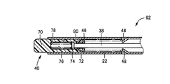
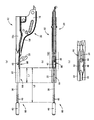
図1の(a) はパーキングブレーキ操作装置60の縦断面図で、(b) はレバー本体62の斜視図、(c) はレリーズロッド38にレリーズノブ40およびポール30が取り付けられたロッド組立体68の斜視図である。図2は、図1の(b) における各部の断面図で、(a) は IIA−IIA 矢視部分すなわちスリット64が設けられた部分の断面図、(b) は IIB−IIB 矢視部分すなわち幅広部66が設けられた部分の断面図、(c) は IIC−IIC 矢視部分の断面図であり、(a) および(b) はグリップ28を併せて示した図である。図3は、レバー本体62のうちレリーズノブ40が配設された先端部分の断面図で、図1(a) に比較して90°位相が異なる略水平面で切断した断面図であり、グリップ28を省略した図である。また、図4はレバー本体62を単独で示す図で、(a) は正面図、(b) は(a) の下方から見た底面図であり、図5はロッド組立体68を単独で示す図で、(a) は正面図、(b) は(a) の下方から見た底面図である。
1A is a longitudinal sectional view of the parking
前記スリット64は、基端部20における逆U字形状の開口に連続して操作部22の下側に設けられ、操作部22の円筒形状の軸方向に延びており、その操作部22の全長に亘って設けられているとともに、前記幅広部66以外の部分の幅寸法W1は、レリーズロッド38を導入可能なように、そのレリーズロッド38の直径dよりも少しだけ大き目の寸法とされている。このスリット64には、図2の(a) から明らかなように、グリップ28の位置決め突起28tが嵌合されるようになっている。スリット64の幅広部66は、操作部22の長手方向の最も基端部20側の部分に設けられているとともに、その幅寸法W2は、レリーズロッド38の前記回動連結部42を導入可能なように、その回動連結部42の幅寸法W4(図5参照)よりも少しだけ大き目の寸法とされている。したがって、そのスリット64を介してレリーズロッド38を操作部22内に導入することができるとともに、そのスリット64の幅広部66を介して、ポール30が取り付けられた回動連結部42を操作部22内に導入することができる。幅広部66の開口端は、図2の(b) から明らかなように、単に間隔を拡げるだけでなく互いに平行な平行部を備えており、所定の剛性が確保されるようになっている。基端部20における一対の側壁18の間隔W3は、前記支持部材14の板厚と略同じ寸法で、ポール30の板厚は、その支持部材14の板厚と同じかそれよりも薄く、一対の側板18の間に挿入可能である。
The
そして、レバー本体62の上記幅広部66が設けられた部分の前端部から操作部22の先端までの距離L1は、ロッド組立体68におけるレリーズロッド38の回動連結部42の前端部からレリーズノブ40までの距離L2よりも短い。これにより、レリーズロッド38にレリーズノブ40およびポール30を取り付けたロッド組立体68の状態で、レリーズロッド38をスリット64から操作部22内に導入することができるとともに、ポール30が取り付けられた回動連結部42をスリット64の幅広部66から操作部22内に導入することができる。上記距離L2は距離L1よりも十分に大きく、圧縮コイルスプリング46をレリーズロッド38に組み付けた状態で、そのレリーズロッド38を操作部22内に導入することができる。
The distance L1 from the front end portion of the
図7は、このようにレリーズロッド38および回動連結部42が操作部22内に導入された状態であり、この状態からロッド組立体68をレバー本体62の基端部20側、すなわち図7の右方向へスライド移動させることにより、図1の(a) に示す所定の組付位置までロッド組立体68を挿入し、ポールピン32によってポール30をレバー本体62に回動可能に連結することにより、そのロッド組立体68がレバー本体62に組み付けられる。また、圧縮コイルスプリング46は、レリーズノブ40と反対側の端部が操作部22に設けられた係止爪48に係止され、所定の圧縮状態とされて、レリーズノブ40を操作部22から突き出す方向へ付勢するとともに、そのレリーズノブ40およびレリーズロッド38を介してポール30を噛合い方向へ付勢する。図6は、上記ロッド組立体68をレバー本体62に組み付ける際の手順を説明する図で、白抜き矢印Aは、図7に示すように操作部22内にレリーズロッド38を導入する工程であり、白抜き矢印Bは、ロッド組立体68を図7の右方向へスライド移動させて所定の組付位置まで挿入する工程である。
FIG. 7 shows a state in which the
また、本実施例のレリーズノブ40は、図3に示すように操作部22の先端から一部が突き出すノブ本体70と、前記圧縮コイルスプリング46の端部が当接させられるばね受け部材72とを別体に備えている。ばね受け部材72の軸心には貫通穴が設けられ、レリーズロッド38が軸方向の相対移動可能に挿通させられているとともに、そのレリーズロッド38の大径頭部74はノブ本体70に係止されるようになっている。ノブ本体70には、大径頭部74が軸方向の相対移動可能に収容される収容穴76が設けられているとともに、その収容穴76内には、ノブ本体70と大径頭部74との間に圧縮コイルスプリング78が配設されており、ノブ本体70が操作部22の先端から突き出す方向へ付勢されるとともに、常には大径頭部74がノブ本体70の係止壁80に着座する状態に保持される。ノブ本体70には、大径頭部74を収容穴76内へ導入できるように、その収容穴76に連通する切欠等が設けられている。なお、図1の(a) および図3以外ではレリーズノブ40を簡略化し、単純な円柱形状で表している。
Further, as shown in FIG. 3, the
このようなレリーズノブ40によれば、車両の駐車時などに操作レバー10がブレーキ操作(引き上げ操作)され、ポール30とラチェット34との噛合いによりパーキングブレーキ作動状態に保持されている場合に、乗員の乗降時等に身体がノブ本体70に接触しても、ノブ本体70が圧縮コイルスプリング78を撓み変形させつつレバー本体62内に押し込まれるだけで、ポール30が回動してラチェット34との噛合いが解除されることはなく、パーキングブレーキの作動状態が維持される。すなわち、パーキングブレーキの作動時には、ブレーキケーブルの張力によってポール30は比較的大きな力でラチェット34と噛み合わされているため、ノブ本体70内に配設された圧縮コイルスプリング78が撓み変形させられるだけで、レリーズロッド38を押し動かしてポール30を回動させることはできないのである。これに対し、パーキングブレーキを解除する場合には、ブレーキケーブルの張力に抗して操作レバー10を僅かに引き上げれば、ポール30とラチェット34との噛合い力が低下し、その状態でノブ本体70を押込み操作すれば、圧縮コイルスプリング78を介してレリーズロッド38がノブ本体70と一体的に押し動かされ、ポール30とラチェット34との噛合いが解除されて操作レバー10を初期位置まで戻し操作することが許容される。
According to such a
このように、本実施例のパーキングブレーキ操作装置60においては、円筒形状の操作部22の軸方向に設けられたスリット64が、レリーズロッド38を導入可能な幅寸法W1を有するとともに、回動連結部42を導入可能な幅広部66を備えており、そのスリット64を介してレリーズロッド38および回動連結部42を操作部22内に導入することが可能で、レリーズロッド38にポール30およびレリーズノブ40が予め取り付けられたロッド組立体68の状態で、図6の矢印A、Bで示すように移動させてレバー本体62内の所定位置に組み付けることができる。すなわち、レリーズロッド38にポール30およびレリーズノブ40を取り付けた状態で、レバー本体62に対して効率的に組み付けることができるのである。また、支持部材14によって支持される基端部20から離れた操作部22のスリット64に幅広部66が設けられるため、大きな操作力が作用する基端部20に幅広部を設ける場合に比較してレバー本体62の剛性低下が抑制されるとともに、円筒形状の操作部22に設けられたスリット64の幅寸法W1を部分的に大きくするだけで良いため意匠が良好に維持される。
As described above, in the parking
また、上記幅広部66はスリット64の長手方向において最も基端部20側の部分に設けられているとともに、その幅広部66から操作部22の先端までの距離L1が、レリーズロッド38の回動連結部42からレリーズノブ40までの距離L2よりも短いため、そのレリーズロッド38にポール30およびレリーズノブ40を取り付けたロッド組立体68の状態で、スリット64を介してレリーズロッド38および回動連結部42を操作部22内に導入することができる。そして、レバー本体62の基端部20側へ移動させることにより、レリーズノブ40が操作部22の先端開口から操作部22内に挿入され、そのレリーズノブ40、レリーズロッド38、およびポール30がレバー本体62内の所定位置に組み付けられる。その場合に、幅広部66がスリット64の最も基端部20側に設けられていることから、操作部22を把持して操作する際の操作フィーリングの低下が抑制される。すなわち、操作部22を把持して操作する際には、一般に操作部22の中でも先端側部分が把持される場合が多いため、幅広部66の存在に起因する操作フィーリングの低下を最小限に抑制することができるのである。
The
以上、本発明の実施例を図面に基づいて詳細に説明したが、これはあくまでも一実施形態であり、本発明は当業者の知識に基づいて種々の変更,改良を加えた態様で実施することができる。 As mentioned above, although the Example of this invention was described in detail based on drawing, this is an embodiment to the last, and this invention implements in the aspect which added various change and improvement based on the knowledge of those skilled in the art. Can do.
14:支持部材 20:基端部 22:操作部 30:ポール 34:ラチェット 38:レリーズロッド 40:レリーズノブ 42:回動連結部 46:圧縮コイルスプリング(付勢手段) 60:パーキングブレーキ操作装置 62:レバー本体 64:スリット 66:幅広部 14: Support member 20: Base end portion 22: Operation portion 30: Pole 34: Ratchet 38: Release rod 40: Release knob 42: Rotating connecting portion 46: Compression coil spring (biasing means) 60: Parking brake operation device 62: Lever body 64: Slit 66: Wide part
Claims (2)
該レバー本体の前記基端部の内側に回動可能に配設され、付勢手段の付勢力に従って前記支持部材に設けられたラチェットと噛み合わされることにより、該レバー本体の回動を規制してパーキングブレーキの作動状態を維持するポールと、
該ポールに相対回動可能に連結され、前記操作部の先端から突き出すレリーズノブが押込み操作されることにより、該ポールを回動させて前記ラチェットとの噛合いを解除するレリーズロッドと、
を有するパーキングブレーキ操作装置において、
前記操作部には、前記基端部における前記逆U字形状の開口に連続して前記円筒形状の軸方向に延びるスリットが設けられている一方、
該スリットは前記レリーズロッドを導入可能な幅寸法を有するとともに、該スリットには該レリーズロッドと前記ポールとの回動連結部を導入可能な幅広部が、該スリットの長手方向の最も前記基端部側に設けられており、
且つ、該幅広部は互いに平行な平行部を備えており、
該スリットを介して前記レリーズロッドおよび前記回動連結部が前記操作部内に導入され、その状態で前記基端部側へ移動させられることにより、該レリーズロッドおよび前記ポールが前記レバー本体の所定位置に組み付けられる
ことを特徴とするパーキングブレーキ操作装置。 A lever main body having a base end portion having a substantially inverted U-shaped cross section and a substantially cylindrical operation portion, the base end portion being disposed so as to straddle the support member and rotatably supported; ,
The lever body is rotatably disposed inside the base end portion, and is engaged with a ratchet provided on the support member according to the urging force of the urging means, thereby restricting the rotation of the lever body. A pole to maintain the parking brake operating state,
A release rod connected to the pole so as to be relatively rotatable, and a release knob protruding from the tip of the operation portion is pushed to release the mesh with the ratchet by rotating the pole; and
In a parking brake operating device having
While the operation portion is provided with a slit extending in the axial direction of the cylindrical shape continuously to the inverted U-shaped opening at the base end portion,
The slit has a width that allows the release rod to be introduced, and the slit has a wide portion into which the rotation connecting portion between the release rod and the pole can be introduced , and is the most proximal end in the longitudinal direction of the slit. It is provided on the part side ,
The wide portion includes parallel portions parallel to each other,
The release rod and the rotation connecting portion are introduced into the operation portion through the slit, and are moved to the base end side in this state, so that the release rod and the pole are in a predetermined position of the lever body. A parking brake operating device characterized by being assembled to
ことを特徴とする請求項1に記載のパーキングブレーキ操作装置。 Distance L1 to the tip of the wide portion or al the operating unit, the parking brake operating device according to claim 1, wherein from the pivotal connecting portion of the release rod is shorter than the distance L2 to the Rerizunobu .
Priority Applications (5)
| Application Number | Priority Date | Filing Date | Title |
|---|---|---|---|
| JP2011130724A JP5455980B2 (en) | 2011-06-10 | 2011-06-10 | Parking brake operation device |
| US14/124,918 US9823682B2 (en) | 2011-06-10 | 2012-04-17 | Parking brake operating device |
| EP12797432.7A EP2719586A4 (en) | 2011-06-10 | 2012-04-17 | Device for operating parking brake |
| CN201280028497.7A CN103596820B (en) | 2011-06-10 | 2012-04-17 | Brake operated device in vehicles |
| PCT/JP2012/060384 WO2012169283A1 (en) | 2011-06-10 | 2012-04-17 | Device for operating parking brake |
Applications Claiming Priority (1)
| Application Number | Priority Date | Filing Date | Title |
|---|---|---|---|
| JP2011130724A JP5455980B2 (en) | 2011-06-10 | 2011-06-10 | Parking brake operation device |
Publications (3)
| Publication Number | Publication Date |
|---|---|
| JP2013001137A JP2013001137A (en) | 2013-01-07 |
| JP2013001137A5 JP2013001137A5 (en) | 2013-11-28 |
| JP5455980B2 true JP5455980B2 (en) | 2014-03-26 |
Family
ID=47295854
Family Applications (1)
| Application Number | Title | Priority Date | Filing Date |
|---|---|---|---|
| JP2011130724A Active JP5455980B2 (en) | 2011-06-10 | 2011-06-10 | Parking brake operation device |
Country Status (5)
| Country | Link |
|---|---|
| US (1) | US9823682B2 (en) |
| EP (1) | EP2719586A4 (en) |
| JP (1) | JP5455980B2 (en) |
| CN (1) | CN103596820B (en) |
| WO (1) | WO2012169283A1 (en) |
Families Citing this family (2)
| Publication number | Priority date | Publication date | Assignee | Title |
|---|---|---|---|---|
| JP6641259B2 (en) * | 2016-10-13 | 2020-02-05 | 豊田鉄工株式会社 | Parking brake lever device |
| JP7159125B2 (en) * | 2019-07-25 | 2022-10-24 | 豊田鉄工株式会社 | Parking brake operating device |
Family Cites Families (14)
| Publication number | Priority date | Publication date | Assignee | Title |
|---|---|---|---|---|
| FR2083487B3 (en) * | 1970-03-23 | 1973-12-28 | Otsukakoki Kk | |
| DE3428156A1 (en) * | 1984-07-31 | 1986-02-13 | Adam Opel AG, 6090 Rüsselsheim | Lockable handbrake lever |
| DE3727625C1 (en) * | 1987-08-19 | 1989-01-26 | Opel Adam Ag | Handbrake lever for a parking brake |
| US4876914A (en) * | 1988-05-26 | 1989-10-31 | Toyoda Iron Works Co., Ltd. | Parking-brake operating device |
| JPH03108572U (en) * | 1990-02-22 | 1991-11-07 | ||
| DE4134052A1 (en) * | 1991-10-15 | 1993-04-22 | Scharwaechter Gmbh Co Kg | ACTUATING DEVICE FOR THE HAND BRAKE OF MOTOR VEHICLES |
| JP3256410B2 (en) * | 1995-05-31 | 2002-02-12 | トヨタ自動車株式会社 | Operating lever for parking brake |
| DE19847524C2 (en) * | 1998-10-15 | 2002-05-16 | Kendrion Rsl Gmbh & Co Kg | Hand brake levers for motor vehicles |
| JP3926493B2 (en) * | 1998-12-18 | 2007-06-06 | スズキ株式会社 | Parking brake lever |
| KR100559911B1 (en) * | 2004-08-17 | 2006-03-15 | 현대자동차주식회사 | parking lever system of a vehicle |
| US20070137405A1 (en) * | 2005-11-18 | 2007-06-21 | Pereira Ryan M | Parkbrake release mechanism and method of use |
| JP4580332B2 (en) * | 2005-12-16 | 2010-11-10 | 本田技研工業株式会社 | Parking brake device |
| JP2007276520A (en) | 2006-04-03 | 2007-10-25 | Hino Motors Ltd | Operation lever device for vehicle |
| JP4500793B2 (en) * | 2006-09-22 | 2010-07-14 | 豊田鉄工株式会社 | Parking brake control lever grip |
-
2011
- 2011-06-10 JP JP2011130724A patent/JP5455980B2/en active Active
-
2012
- 2012-04-17 WO PCT/JP2012/060384 patent/WO2012169283A1/en active Application Filing
- 2012-04-17 US US14/124,918 patent/US9823682B2/en not_active Expired - Fee Related
- 2012-04-17 CN CN201280028497.7A patent/CN103596820B/en not_active Expired - Fee Related
- 2012-04-17 EP EP12797432.7A patent/EP2719586A4/en not_active Withdrawn
Also Published As
| Publication number | Publication date |
|---|---|
| JP2013001137A (en) | 2013-01-07 |
| US9823682B2 (en) | 2017-11-21 |
| US20140245854A1 (en) | 2014-09-04 |
| CN103596820A (en) | 2014-02-19 |
| WO2012169283A1 (en) | 2012-12-13 |
| CN103596820B (en) | 2016-06-29 |
| EP2719586A1 (en) | 2014-04-16 |
| EP2719586A4 (en) | 2016-06-08 |
Similar Documents
| Publication | Publication Date | Title |
|---|---|---|
| JP4939299B2 (en) | Vehicle door handle device | |
| JP4176120B2 (en) | Vehicle locking device | |
| JP4397378B2 (en) | Vehicle storage device | |
| GB2525038A (en) | Lever | |
| JP5287128B2 (en) | Vehicle seat slide device | |
| US7637180B2 (en) | Parking brake apparatus | |
| JP2010052673A (en) | Shift lever device | |
| JP5455980B2 (en) | Parking brake operation device | |
| JP6236376B2 (en) | Parking brake operation device | |
| JP5235815B2 (en) | Vehicle door handle device | |
| US20070151396A1 (en) | Parking brake | |
| JP5448694B2 (en) | Assembly structure of unlocking operation member for vehicle seat and lock / unlock device for vehicle seat | |
| JP4510101B2 (en) | connector | |
| JP5400427B2 (en) | Seat locking / unlocking device | |
| JP2010083183A (en) | Wiper device and connecting member | |
| JP5964649B2 (en) | Parking brake rattling prevention structure and parking brake having the rattling prevention structure | |
| JP5276918B2 (en) | Slide rail device for vehicle | |
| JP4719588B2 (en) | Control cable terminal support device | |
| JP2010125955A (en) | Slide rail apparatus for vehicle | |
| JP6140113B2 (en) | Parking brake lever device | |
| JP4672630B2 (en) | Parking brake device | |
| JP4169751B2 (en) | Parking brake device | |
| JP4459075B2 (en) | Operation wire mounting structure | |
| JP5721260B2 (en) | Door lock | |
| JP2012038155A (en) | Operation wire drawing place adjusting device |
Legal Events
| Date | Code | Title | Description |
|---|---|---|---|
| A621 | Written request for application examination |
Free format text: JAPANESE INTERMEDIATE CODE: A621 Effective date: 20130606 |
|
| A521 | Written amendment |
Free format text: JAPANESE INTERMEDIATE CODE: A523 Effective date: 20131011 |
|
| A871 | Explanation of circumstances concerning accelerated examination |
Free format text: JAPANESE INTERMEDIATE CODE: A871 Effective date: 20131011 |
|
| TRDD | Decision of grant or rejection written | ||
| A975 | Report on accelerated examination |
Free format text: JAPANESE INTERMEDIATE CODE: A971005 Effective date: 20131210 |
|
| A01 | Written decision to grant a patent or to grant a registration (utility model) |
Free format text: JAPANESE INTERMEDIATE CODE: A01 Effective date: 20131217 |
|
| A61 | First payment of annual fees (during grant procedure) |
Free format text: JAPANESE INTERMEDIATE CODE: A61 Effective date: 20140107 |
|
| R150 | Certificate of patent or registration of utility model |
Ref document number: 5455980 Country of ref document: JP Free format text: JAPANESE INTERMEDIATE CODE: R150 |
|
| R250 | Receipt of annual fees |
Free format text: JAPANESE INTERMEDIATE CODE: R250 |
|
| R250 | Receipt of annual fees |
Free format text: JAPANESE INTERMEDIATE CODE: R250 |
|
| R250 | Receipt of annual fees |
Free format text: JAPANESE INTERMEDIATE CODE: R250 |
|
| R250 | Receipt of annual fees |
Free format text: JAPANESE INTERMEDIATE CODE: R250 |
|
| R250 | Receipt of annual fees |
Free format text: JAPANESE INTERMEDIATE CODE: R250 |
|
| R250 | Receipt of annual fees |
Free format text: JAPANESE INTERMEDIATE CODE: R250 |
|
| R250 | Receipt of annual fees |
Free format text: JAPANESE INTERMEDIATE CODE: R250 |