JP5449338B2 - Sensor housing cover and method of manufacturing sensor housing cover - Google Patents
Sensor housing cover and method of manufacturing sensor housing cover Download PDFInfo
- Publication number
- JP5449338B2 JP5449338B2 JP2011515263A JP2011515263A JP5449338B2 JP 5449338 B2 JP5449338 B2 JP 5449338B2 JP 2011515263 A JP2011515263 A JP 2011515263A JP 2011515263 A JP2011515263 A JP 2011515263A JP 5449338 B2 JP5449338 B2 JP 5449338B2
- Authority
- JP
- Japan
- Prior art keywords
- sensor housing
- housing cover
- cover
- base cover
- plastic
- Prior art date
- Legal status (The legal status is an assumption and is not a legal conclusion. Google has not performed a legal analysis and makes no representation as to the accuracy of the status listed.)
- Expired - Fee Related
Links
Images


Classifications
-
- G—PHYSICS
- G01—MEASURING; TESTING
- G01D—MEASURING NOT SPECIALLY ADAPTED FOR A SPECIFIC VARIABLE; ARRANGEMENTS FOR MEASURING TWO OR MORE VARIABLES NOT COVERED IN A SINGLE OTHER SUBCLASS; TARIFF METERING APPARATUS; MEASURING OR TESTING NOT OTHERWISE PROVIDED FOR
- G01D11/00—Component parts of measuring arrangements not specially adapted for a specific variable
- G01D11/24—Housings ; Casings for instruments
- G01D11/245—Housings for sensors
Landscapes
- Physics & Mathematics (AREA)
- General Physics & Mathematics (AREA)
- Measuring Fluid Pressure (AREA)
- Force Measurement Appropriate To Specific Purposes (AREA)
Description
本発明は、センサハウジングカバー及びセンサハウジングカバーを製造する方法に関する。 The present invention relates to a sensor housing cover and a method for manufacturing the sensor housing cover.
DE102006018031A1に基づいて、空気圧センサを車両の側部に組み込むことが公知であり、これによって側面衝突を、該衝突時に車両側部において生じる空気圧上昇によって、認識することができる。 Based on DE 102006018031 A1, it is known to incorporate an air pressure sensor into the side of a vehicle, whereby a side collision can be recognized by an increase in air pressure occurring at the side of the vehicle at the time of the collision.
発明の開示
ベースカバーを備えたセンサハウジングカバーであって、ベースカバーが少なくとも1つの貫通孔を有しており、ベースカバーが第1のプラスチックによって射出被覆されて、該第1のプラスチックがセンサハウジングカバーの少なくとも1つのエレメントを形成し、少なくとも1つの貫通孔を介してベースカバーと形状結合式に結合されていることを特徴とするセンサハウジングカバー、もしくはセンサハウジングカバーを製造する方法であって、下記の方向ステップ、すなわち:
- 少なくとも1つの貫通孔を備えたベースカバーの準備、
- 1つの型によるベースカバーの取り囲み、
- センサハウジングカバーの少なくとも1つのエレメントの製造を目的とした、型内へのプラスチックの射出、という方法ステップを有していて、射出されたプラスチックを、少なくとも1つの貫通孔を介してベースカバーと形状結合式に結合させることを特徴とする、センサハウジングカバーを製造する方法には、公知のものに対して次のような利点がある。すなわち本発明によるセンサハウジングカバーもしくはセンサハウジングカバーを製造する方法では、センサハウジングカバーは単にベースカバーと、該ベースカバーを射出被覆するプラスチックとから成っており、射出されたプラスチックとベースカバーとの間の結合は、少なくとも1つの貫通孔を介して形状結合によって達成される。これによって、異なった材料の数は2つに減じられ、ベースカバーと該ベースカバーを射出被覆するプラスチックとの間における付着もしくは固着の問題は、形状結合によって回避される。特に本発明を空気圧センサのために使用すると、材料移行部の数が減じられ、その結果このような空気圧センサをドアの熱結合金属薄板に固定する場合における、非シール性の蓋然性が最小になる。
DISCLOSURE OF THE INVENTION A sensor housing cover with a base cover, the base cover having at least one through hole, the base cover being injection-coated with a first plastic, the first plastic being a sensor housing A sensor housing cover, or a method of manufacturing a sensor housing cover, characterized in that it forms at least one element of a cover and is connected to the base cover through at least one through hole in a shape-coupled manner, The following direction steps:
-Preparation of a base cover with at least one through-hole,
-Surrounding the base cover with one mold,
-Having the method step of injecting plastic into a mold for the manufacture of at least one element of the sensor housing cover, the injected plastic being connected to the base cover via at least one through hole; The method of manufacturing the sensor housing cover, which is characterized by being coupled in a shape coupling manner, has the following advantages over the known ones. That is, in the sensor housing cover or the method of manufacturing the sensor housing cover according to the present invention, the sensor housing cover is simply composed of a base cover and a plastic that covers the base cover by injection coating, and between the injected plastic and the base cover. The coupling is achieved by shape coupling through at least one through hole. This reduces the number of different materials to two and the problem of adhesion or sticking between the base cover and the plastic that is injection-coated on the base cover is avoided by shape bonding. In particular, when the present invention is used for a pneumatic sensor, the number of material transitions is reduced, so that the probability of non-sealing is minimized when such a pneumatic sensor is secured to a thermally bonded sheet metal of a door. .
この単純な構造により、コストが減じられる。また射出被覆するプラスチックはシールの働きをも引き受けることができる。これによって、欠陥もしくは故障箇所の発生が減じられる。 This simple structure reduces costs. The plastic to be injection coated can also take on the function of a seal. This reduces the occurrence of defects or failure points.
本発明による方法は、単純な射出成形プロセスによって実現することができる。最終組立てプロセスが省かれるので、これによってもコストが削減される。 The method according to the invention can be realized by a simple injection molding process. This also reduces costs since the final assembly process is omitted.
本発明では、センサハウジングカバーはセンサハウジングを閉鎖するために設けられている。このセンサハウジングカバーは本発明におけるように構成されている。 In the present invention, the sensor housing cover is provided to close the sensor housing. This sensor housing cover is constructed as in the present invention.
従属請求項記載のように構成することができるベースカバーは、本発明によれば少なくとも1つの貫通孔を有しており、これによりベースカバーと該ベースカバーを射出被覆するプラスチックとは互いに形状結合によって結合される。 According to the invention, the base cover, which can be configured as defined in the dependent claims, has at least one through-hole, whereby the base cover and the plastic which is injection-coated on the base cover are in shape connection with each other Combined by.
射出被覆(umspritzen)を行う射出成形法のために適したプラスチックは、従属請求項記載のように構成されている。特に、第1のプラスチックがセンサハウジングカバーの少なくとも1つのエレメントを形成するということが、射出被覆によって可能である。そのために製造方法では、このエレメントの形成と射出成形法における製造とを可能にする型が提案されている。前記エレメントは従属請求項によって規定されている。 Plastics suitable for injection molding with injection coating (umspritzen) are configured as defined in the dependent claims. In particular, it is possible by injection coating that the first plastic forms at least one element of the sensor housing cover. Therefore, in the manufacturing method, a mold that enables the formation of the element and the manufacturing by the injection molding method has been proposed. Said elements are defined by the dependent claims.
少なくとも1つの貫通孔は、使用されるセンサ型式に応じて種々様々な構成を有することができる。1つの空気圧センサでは、少なくとも1つの貫通孔が例えば圧力流入通路を形成するために設けられている。 The at least one through hole can have a wide variety of configurations depending on the sensor type used. In one air pressure sensor, at least one through hole is provided to form, for example, a pressure inflow passage.
ベースカバーのセンサハウジングカバーを製造する方法における準備というのは、ベースカバーがそれ自体製造されるか又は購入され、その結果ベースカバーが既に存在していることを意味する。 Preparation in the method of manufacturing the sensor housing cover of the base cover means that the base cover is manufactured or purchased as a result, so that the base cover already exists.
型は種々様々な構成のものが可能であり、例えば2部分から成る型が可能である。特に、上型と下型とを設けて、両方の型を次いで密につまりシール作用をもって閉鎖することが可能である。さらに、圧力流入通路を射出成形時に規定するために、互いに接触させられる複数のスライダが設けられていてもよい。圧力流入通路はこの場合通常屈曲部を有している。これらのスライドエレメント又はスライダは、次いで冷却後に再び引き戻され、上型と下型とは開放されて、センサハウジングカバーが製造される。 The mold can have a variety of configurations, for example, a two-part mold. In particular, it is possible to provide an upper mold and a lower mold and then close both molds tightly, ie with a sealing action. Further, a plurality of sliders that are brought into contact with each other may be provided in order to define the pressure inflow passage during injection molding. In this case, the pressure inlet passage usually has a bent portion. These slide elements or sliders are then pulled back after cooling and the upper and lower molds are opened to produce the sensor housing cover.
独立請求項に記載されたセンサハウジングカバーもしくはこのようなセンサハウジングカバーを製造する方法のさらなる有利な構成は、従属請求項に記載されている。 Further advantageous configurations of the sensor housing cover as set forth in the independent claims or the method of manufacturing such a sensor housing cover are set forth in the dependent claims.
ベースカバーが主として、加水分解安定性を有する第2のプラスチックから成っていると、有利である。このような加水分解安定性を有するプラスチックは、該プラスチックがアルカリ液に対して耐性を有するように、化学的に変化させられる。この場合例えば、PBT GF30のような市販のプラスチックをハウジングプラスチックとして、例えばBASF B4300のウルトラデュアー(Ultradur)を内室使用のために使用することができる。センサがウェザールーム、つまり天候の影響を受ける所において、例えば車両フロントにおいてクラッシュセンサとして使用される前面センサもしくはアップフロントセンサとして、使用される場合には、加水分解安定性を有するPBT GF30、例えばCrastin-CE 2510又はRaditer BIRV 4008 TKB381を使用することができる。つまり、ポリブチレンテレフタレート(PBT)は60°以上で、水及び湿気中の熱によって化学的に加水分解によって分解され得る、という問題がある。相応な安定化によって、この支承特性を改善することができる。このことは特殊な化学的改質によって可能である。この効果は定量的かつ段階的であり、その結果特性の基本的な変化が生じることはない。それというのはPBTの分子構造における第1群が盲点もしくは弱点だからである。 It is advantageous if the base cover mainly consists of a second plastic having hydrolytic stability. Such a plastic having hydrolytic stability is chemically changed so that the plastic has resistance to an alkaline liquid. In this case, for example, a commercially available plastic such as PBT GF30 can be used as the housing plastic, for example a BASF B4300 Ultradur for use in the interior. PBT GF30 having hydrolytic stability, for example Crastin, if the sensor is used in a weather room, i.e. where it is affected by the weather, for example as a front sensor or as an upfront sensor used as a crash sensor at the front of the vehicle -CE 2510 or Radiator BIRV 4008 TKB381 can be used. That is, there is a problem that polybutylene terephthalate (PBT) is 60 ° or more and can be decomposed by hydrolysis by heat in water and moisture. The bearing characteristics can be improved by corresponding stabilization. This is possible by special chemical modification. This effect is quantitative and gradual so that no fundamental change in properties occurs. This is because the first group in the molecular structure of PBT is a blind spot or a weak spot.
さらに、ベースカバーが一体に構成されていると、有利であり、このような構成は、特に簡単な製造のために寄与する。 Furthermore, it is advantageous if the base cover is constructed in one piece, and such a configuration contributes particularly for simple production.
別の有利な構成では、ベースカバーが、圧力流入通路のための1つの第1の貫通孔と、形状結合のための2つの別の貫通孔とを有しており、第1の貫通孔が、2つの別の貫通孔よりも大きく形成されている。別の貫通孔の数を2つよりもさらに増やすと、これによる形状結合をさらに改善することができる。 In another advantageous configuration, the base cover has one first through hole for the pressure inflow passage and two other through holes for shape coupling, the first through hole being It is formed larger than two separate through holes. If the number of other through holes is further increased from two, the shape coupling due to this can be further improved.
有利には第1のプラスチックがシリコンであり、これは射出成形もしくは射出被覆のための極めて適している。第1のプラスチック、つまりシリコンも例えば一体に形成されていることができ、このようになっていると、センサハウジングカバーは単に2部分から構成されることになり、製造及びコストの点で利点が得られる。 The first plastic is preferably silicon, which is very suitable for injection molding or injection coating. The first plastic, i.e. silicon, can also be formed, for example, in one piece, so that the sensor housing cover simply consists of two parts, which is advantageous in terms of manufacturing and cost. can get.
少なくとも1つのエレメントが、センサのための内側のシール部材であると、有利である。このような構成は特に、空気圧センサのために有利である。しかしながらまた少なくとも1つのエレメントは、圧力流入通路であってもよく、また上に述べたように、例えばドア金属薄板のための外側のシール部材であってもよい。 Advantageously, at least one element is an inner sealing member for the sensor. Such a configuration is particularly advantageous for pneumatic sensors. However, the at least one element may also be a pressure inlet passage and, as mentioned above, for example an outer sealing member for a door sheet metal.
次に図面を参照しながら本発明の実施形態を説明する。 Next, embodiments of the present invention will be described with reference to the drawings.
図1aには、センサハウジングカバーを下から見た図が示されている。この図1aには、ウェブ103,104と、形状結合(Formschluss)のために使用される貫通孔101,102が示されている。実線で示された加水分解安定性を有するプラスチックとは異なり、破線で示されているシリコンによって、形状結合のための貫通孔101,102の周囲への拡大が示され、かつ圧力流入通路100の定義もしくは範囲規定も示されている。
FIG. 1a shows a view of the sensor housing cover from below. In this FIG. 1a,
図1bにはセンサハウジングカバーが側面図で示されている。この図1bにおいても実線によってベースカバーが加水分解安定性を有するプラスチックと共に示されている。破線で示されたシリコンによって、圧力流入通路105が規定され、かつ貫通孔101,102による形状結合部の周囲への拡大部106,107を実現することができる。図1bにはさらに、センサの内部への圧力流入通路110の定義もしくは範囲規定が示されている。
FIG. 1b shows the sensor housing cover in side view. Also in this FIG. 1b, the base cover is shown with a plastic having hydrolytic stability by a solid line. The silicon shown by the broken line defines the
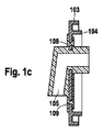
図1cにはセンサハウジングカバーが断面図で示されている。ベースカバーは間隔の狭い斜めのハッチングで示されており、このハッチングは左下から右上に向かって引かれており、これに対してシリコンは、射出被覆もしくは包埋射出成形のために射出されたプラスチックとして同様に斜めのハッチングで示されているが、しかしながらこのハッチングは、ベースカバーに比べて広い間隔をもって右下から左上に向かって引かれている。図1cにはさらに、シリコンによって規定もしくは定義された圧力流入通路105が示されている。このシリコンは図示の場合一体であり、貫通孔101,102と材料部分108,109とによって、ベースカバーとの形状結合部を形成している。符号103,104によって、さらにベースカバーのウェブが示されている。センサ内部への圧力流入通路の定義及びシール部材の定義も示されている。
FIG. 1c shows the sensor housing cover in cross-section. The base cover is shown with closely spaced diagonal hatches, which are drawn from the lower left to the upper right, whereas silicon is plastic injected for injection coating or embedded injection molding Similarly, the hatching is shown as oblique hatching, however, this hatching is drawn from the lower right to the upper left with a wider interval than the base cover. Also shown in FIG. 1c is a
図1dにはセンサハウジングカバーが平面図で示されている。この図1dにおいてもベースカバーのエレメントは実線で示され、シリコン部分は破線で示されている。形状結合部を形成するために孔102,101を貫通している、圧力流入管片又は通路105及び区分106,107も示されている。
FIG. 1d shows the sensor housing cover in plan view. Also in FIG. 1d, the elements of the base cover are indicated by solid lines and the silicon portion is indicated by broken lines. Also shown is a pressure inlet tube segment or
図2には、ドアねじ結合金属薄板及びセンサエレメントと組み合わせられた、本発明によるセンサハウジングカバーが、断面図で示されている。ドアねじ結合金属薄板はエレメント200,203によって示されており、シリコンは、図1におけるベースカバーと同様にハッチングで示されている。センサモジュール202は、幅の狭いハッチングで示されていて、圧力流入通路201を閉鎖している。シールもしくは圧着によって、シール面207,208が形成されている。形状結合は孔204,205を貫いて流れるシリコンの貫流によって達成される。圧力流入管片はここでは、ドアの湿潤室(Nassraum)内へと側方に引き出されて示されている。乾燥室内においては圧力流入通路206の別の部分が延びている。
FIG. 2 shows a sectional view of a sensor housing cover according to the invention in combination with a door screw-coupled sheet metal and a sensor element. The door screw-bonded sheet metal is indicated by
このような形状付与によって明らかなように、圧力流入通路206を通して第1のスライダが、かつ側方に引き出された部分201を通して第2のスライダが、内部に案内され、これによってこの圧力流入通路を射出コース方法(Spritzkursverfahren)において定義することができる。そして両方のスライダは次いで相応に、屈曲部の移行部において互いに出合う。
As is apparent from this shape formation, the first slider is guided through the
図3には、センサハウジングカバーを製造する方法がフローチャートで示されている。方法ステップ300において、少なくとも1つの貫通孔を備えたベースカバーが準備され、この準備というのは、製造をも意味することができる。図1及び図2に示されているように、良好な形状結合部の形成、つまりシリコンとベースカバーと良好な引っ掛かり(Verkrallen)を可能にするために、2つ以上の貫通孔を設けることが可能である。
FIG. 3 is a flowchart showing a method for manufacturing the sensor housing cover. In
方法ステップ301において、ベースカバーは、2部分から成る型、つまり上型と下型とによって取り囲まれる。これらの型は密にシール作用をもって閉鎖される。これらの型は、射出コースにおけるようにシリコンのようなエレメントを規定したいように形成するために、必要である。
In
方法ステップ302において、圧力流入通路201,206の定義を可能にするために、スライドエレメントが互いに接触させられる。このことは例えば上に述べたように行うことができる。
In
方法ステップ303において、シリコンの射出注入が行われる。
In
方法ステップ304において初めに、射出注入の後の冷却が行われ、次いでスライドエレメント又はスライダが引き戻される。その後で型は開放され、センサハウジングカバーは完成する。
Initially in
Claims (13)
- 圧力流入通路のための少なくとも1つの貫通孔と、形状結合のための少なくとも1つの別の貫通孔(101,102)とを備えたベースカバーの準備、
- 1つの型によるベースカバーの取り囲み、
- センサハウジングカバーの少なくとも1つのエレメントの製造を目的とした、型内へのプラスチックの射出、という方法ステップを有していて、射出されたプラスチックを、前記別の貫通孔(101,102)を介してベースカバーと形状結合式に結合させることを特徴とする、センサハウジングカバーを製造する方法。 A method of manufacturing a sensor housing cover comprising the following method steps:
- at least one through-hole, ready for base cover and at least one further through-hole for the form-fitting (101, 102) for the pressure inlet passage,
-Surrounding the base cover with one mold,
-Having the method step of injection of plastic into the mold for the purpose of producing at least one element of the sensor housing cover, the injected plastic being passed through said further through-holes (101, 102) A method of manufacturing a sensor housing cover, characterized in that the sensor housing cover is coupled to the base cover in a shape coupling manner.
Applications Claiming Priority (3)
| Application Number | Priority Date | Filing Date | Title |
|---|---|---|---|
| DE102008040155.2 | 2008-07-03 | ||
| DE102008040155A DE102008040155A1 (en) | 2008-07-03 | 2008-07-03 | Sensor housing cover and method of making such a sensor housing cover |
| PCT/EP2009/055373 WO2010000526A1 (en) | 2008-07-03 | 2009-05-05 | Sensor housing cover and method for producing such a sensor housing cover |
Publications (2)
| Publication Number | Publication Date |
|---|---|
| JP2011526363A JP2011526363A (en) | 2011-10-06 |
| JP5449338B2 true JP5449338B2 (en) | 2014-03-19 |
Family
ID=41305331
Family Applications (1)
| Application Number | Title | Priority Date | Filing Date |
|---|---|---|---|
| JP2011515263A Expired - Fee Related JP5449338B2 (en) | 2008-07-03 | 2009-05-05 | Sensor housing cover and method of manufacturing sensor housing cover |
Country Status (6)
| Country | Link |
|---|---|
| US (1) | US8707783B2 (en) |
| EP (1) | EP2307858A1 (en) |
| JP (1) | JP5449338B2 (en) |
| CN (1) | CN102084222B (en) |
| DE (1) | DE102008040155A1 (en) |
| WO (1) | WO2010000526A1 (en) |
Cited By (1)
| Publication number | Priority date | Publication date | Assignee | Title |
|---|---|---|---|---|
| JP2016506522A (en) * | 2012-12-27 | 2016-03-03 | ローベルト ボッシュ ゲゼルシャフト ミット ベシュレンクテル ハフツング | Detection device and method for manufacturing the detection device |
Families Citing this family (9)
| Publication number | Priority date | Publication date | Assignee | Title |
|---|---|---|---|---|
| DE102008054743A1 (en) * | 2008-12-16 | 2010-06-17 | Robert Bosch Gmbh | Apparatus and method for manufacturing a device |
| US10591124B2 (en) | 2012-08-30 | 2020-03-17 | Sabic Global Technologies B.V. | Heat dissipating system for a light, headlamp assembly comprising the same, and method of dissipating heat |
| DE102013208534A1 (en) * | 2012-12-27 | 2014-07-03 | Robert Bosch Gmbh | Method for producing a sensor housing and corresponding sensor housing |
| DE102013208545A1 (en) | 2012-12-27 | 2014-07-03 | Robert Bosch Gmbh | Detection device and method for producing a detection device |
| JP6237457B2 (en) * | 2014-05-14 | 2017-11-29 | 株式会社デンソー | Pressure sensor |
| US10352796B2 (en) * | 2014-07-28 | 2019-07-16 | Ford Global Technologies, Llc | Protective cover for pressure sensor nozzle |
| US9470595B2 (en) * | 2014-08-29 | 2016-10-18 | Trw Automotive U.S. Llc | Apparatus for dry side mounting a crash pressure sensor |
| US10605686B2 (en) * | 2017-10-19 | 2020-03-31 | Veoneer Us, Inc. | Dual wet and dry combination mounting |
| US11808098B2 (en) | 2018-08-20 | 2023-11-07 | DynaEnergetics Europe GmbH | System and method to deploy and control autonomous devices |
Family Cites Families (15)
| Publication number | Priority date | Publication date | Assignee | Title |
|---|---|---|---|---|
| US3266312A (en) * | 1964-02-17 | 1966-08-16 | Gen Motors Corp | Level indicator sending unit |
| US4312123A (en) * | 1979-03-12 | 1982-01-26 | Interpace Corporation | Methods of making high voltage electrical insulators and oil-less bushings |
| JPH02107416A (en) * | 1988-10-17 | 1990-04-19 | Three Bond Co Ltd | Molding method for composite article |
| CZ194096A3 (en) * | 1995-07-03 | 1998-09-16 | Robert Bosch Gmbh | Vibration pick-up with pressure casing |
| US5700360A (en) * | 1995-10-31 | 1997-12-23 | Chiron Diagnostics Corporation | Fluoroelastomer gasket for blood sensors |
| DE19923985B4 (en) * | 1999-05-25 | 2006-12-28 | Siemens Ag | Sensor assembly with a wall mountable housing |
| IT1313816B1 (en) * | 1999-11-03 | 2002-09-23 | Gefran Sensori S R L | HIGH PRECISION PRESSURE SENSOR DEVICE |
| DE10022124B4 (en) * | 2000-05-06 | 2010-01-14 | Wabco Gmbh | Electronic control unit |
| PL1664165T3 (en) * | 2003-09-05 | 2014-04-30 | Dow Global Technologies Llc | Improved resin compositions for extrusion coating |
| DE102004018869B4 (en) * | 2004-04-19 | 2008-05-08 | Siemens Ag | Device for detecting the movement of a movable component |
| JP4564775B2 (en) * | 2004-04-26 | 2010-10-20 | 日立オートモティブシステムズ株式会社 | Pressure detector for liquid and gas |
| JP2007064837A (en) | 2005-08-31 | 2007-03-15 | Denso Corp | Pressure sensor |
| DE102006018031B4 (en) | 2006-04-19 | 2019-07-11 | Robert Bosch Gmbh | Sensor arrangement and method for triggering a restraint device |
| DE102006058301B4 (en) * | 2006-12-11 | 2016-12-29 | Robert Bosch Gmbh | Air pressure sensor for side impact detection |
| US7380458B1 (en) * | 2007-03-02 | 2008-06-03 | Autoliv Asp, Inc. | Pressure sensor port |
-
2008
- 2008-07-03 DE DE102008040155A patent/DE102008040155A1/en not_active Withdrawn
-
2009
- 2009-05-05 EP EP09772226A patent/EP2307858A1/en not_active Withdrawn
- 2009-05-05 US US13/002,130 patent/US8707783B2/en not_active Expired - Fee Related
- 2009-05-05 WO PCT/EP2009/055373 patent/WO2010000526A1/en active Application Filing
- 2009-05-05 CN CN2009801256046A patent/CN102084222B/en not_active Expired - Fee Related
- 2009-05-05 JP JP2011515263A patent/JP5449338B2/en not_active Expired - Fee Related
Cited By (1)
| Publication number | Priority date | Publication date | Assignee | Title |
|---|---|---|---|---|
| JP2016506522A (en) * | 2012-12-27 | 2016-03-03 | ローベルト ボッシュ ゲゼルシャフト ミット ベシュレンクテル ハフツング | Detection device and method for manufacturing the detection device |
Also Published As
| Publication number | Publication date |
|---|---|
| US20110174071A1 (en) | 2011-07-21 |
| JP2011526363A (en) | 2011-10-06 |
| CN102084222B (en) | 2013-03-06 |
| US8707783B2 (en) | 2014-04-29 |
| WO2010000526A1 (en) | 2010-01-07 |
| DE102008040155A1 (en) | 2010-01-07 |
| EP2307858A1 (en) | 2011-04-13 |
| CN102084222A (en) | 2011-06-01 |
Similar Documents
| Publication | Publication Date | Title |
|---|---|---|
| JP5449338B2 (en) | Sensor housing cover and method of manufacturing sensor housing cover | |
| JP4717618B2 (en) | Manufacturing method of casing component with ventilation filter and manufacturing method of casing with ventilation filter | |
| CN102414450B (en) | Plastic housing of radial flow compressor | |
| JP5093976B2 (en) | Structure of parts composed of a plurality of members and manufacturing method thereof | |
| US8966757B2 (en) | Plastic heat exchanger and method of manufacturing the same | |
| US7490812B2 (en) | Valve device having a valve control member formed by molding | |
| JP2010137570A (en) | Casing and method of manufacturing the same | |
| JP2007001535A (en) | Method for manufacturing window glass with decorated mold and window glass with decorated mold | |
| JP2005535470A (en) | Improved side sill trim parts and method of molding the parts | |
| JP4894763B2 (en) | Plastic molded product | |
| CA2373108A1 (en) | Plastic stop valve and method for the production thereof | |
| JP5242509B2 (en) | Hole plug | |
| JP2005334637A (en) | Plastic molding for ostomy device | |
| JP2006501082A (en) | Multilayer plastic part injection molding method and multilayer plastic part | |
| JP5971220B2 (en) | Method for manufacturing resin hollow body and air flow measuring device | |
| KR100733499B1 (en) | Manufacturing method of door trim for vehicle | |
| JP3562832B2 (en) | Resin hollow molded article and method for producing the same | |
| JPH04152123A (en) | Blow-molded product having fitting part and its manufacture | |
| JP2519481B2 (en) | Manufacturing method of pipe with flange | |
| JP2000326802A (en) | Weatherstrip and its manufacture | |
| JP3393542B2 (en) | Manufacturing method of resin intake manifold | |
| KR100792879B1 (en) | Manufacturing method of glass run channel for door frame | |
| CN115494256A (en) | Wheel speed sensor and method for manufacturing same | |
| JPH10128760A (en) | Production of elastic hollow member | |
| KR101031152B1 (en) | A brush holder assembly for a window lift motor |
Legal Events
| Date | Code | Title | Description |
|---|---|---|---|
| A977 | Report on retrieval |
Free format text: JAPANESE INTERMEDIATE CODE: A971007 Effective date: 20121119 |
|
| A131 | Notification of reasons for refusal |
Free format text: JAPANESE INTERMEDIATE CODE: A131 Effective date: 20121122 |
|
| A601 | Written request for extension of time |
Free format text: JAPANESE INTERMEDIATE CODE: A601 Effective date: 20130222 |
|
| A602 | Written permission of extension of time |
Free format text: JAPANESE INTERMEDIATE CODE: A602 Effective date: 20130301 |
|
| A521 | Written amendment |
Free format text: JAPANESE INTERMEDIATE CODE: A523 Effective date: 20130514 |
|
| A02 | Decision of refusal |
Free format text: JAPANESE INTERMEDIATE CODE: A02 Effective date: 20130610 |
|
| RD13 | Notification of appointment of power of sub attorney |
Free format text: JAPANESE INTERMEDIATE CODE: A7433 Effective date: 20131002 |
|
| A521 | Written amendment |
Free format text: JAPANESE INTERMEDIATE CODE: A523 Effective date: 20131010 |
|
| A521 | Written amendment |
Free format text: JAPANESE INTERMEDIATE CODE: A821 Effective date: 20131002 |
|
| A911 | Transfer to examiner for re-examination before appeal (zenchi) |
Free format text: JAPANESE INTERMEDIATE CODE: A911 Effective date: 20131030 |
|
| TRDD | Decision of grant or rejection written | ||
| A01 | Written decision to grant a patent or to grant a registration (utility model) |
Free format text: JAPANESE INTERMEDIATE CODE: A01 Effective date: 20131125 |
|
| A61 | First payment of annual fees (during grant procedure) |
Free format text: JAPANESE INTERMEDIATE CODE: A61 Effective date: 20131224 |
|
| R150 | Certificate of patent or registration of utility model |
Ref document number: 5449338 Country of ref document: JP Free format text: JAPANESE INTERMEDIATE CODE: R150 Free format text: JAPANESE INTERMEDIATE CODE: R150 |
|
| R250 | Receipt of annual fees |
Free format text: JAPANESE INTERMEDIATE CODE: R250 |
|
| R250 | Receipt of annual fees |
Free format text: JAPANESE INTERMEDIATE CODE: R250 |
|
| R250 | Receipt of annual fees |
Free format text: JAPANESE INTERMEDIATE CODE: R250 |
|
| R250 | Receipt of annual fees |
Free format text: JAPANESE INTERMEDIATE CODE: R250 |
|
| LAPS | Cancellation because of no payment of annual fees |