DE19923985B4 - Sensor assembly with a wall mountable housing - Google Patents
Sensor assembly with a wall mountable housing Download PDFInfo
- Publication number
- DE19923985B4 DE19923985B4 DE19923985A DE19923985A DE19923985B4 DE 19923985 B4 DE19923985 B4 DE 19923985B4 DE 19923985 A DE19923985 A DE 19923985A DE 19923985 A DE19923985 A DE 19923985A DE 19923985 B4 DE19923985 B4 DE 19923985B4
- Authority
- DE
- Germany
- Prior art keywords
- housing
- pipe socket
- sensor
- sealing
- sensor assembly
- Prior art date
- Legal status (The legal status is an assumption and is not a legal conclusion. Google has not performed a legal analysis and makes no representation as to the accuracy of the status listed.)
- Expired - Fee Related
Links
Classifications
-
- G—PHYSICS
- G01—MEASURING; TESTING
- G01L—MEASURING FORCE, STRESS, TORQUE, WORK, MECHANICAL POWER, MECHANICAL EFFICIENCY, OR FLUID PRESSURE
- G01L19/00—Details of, or accessories for, apparatus for measuring steady or quasi-steady pressure of a fluent medium insofar as such details or accessories are not special to particular types of pressure gauges
- G01L19/14—Housings
-
- G—PHYSICS
- G01—MEASURING; TESTING
- G01D—MEASURING NOT SPECIALLY ADAPTED FOR A SPECIFIC VARIABLE; ARRANGEMENTS FOR MEASURING TWO OR MORE VARIABLES NOT COVERED IN A SINGLE OTHER SUBCLASS; TARIFF METERING APPARATUS; MEASURING OR TESTING NOT OTHERWISE PROVIDED FOR
- G01D11/00—Component parts of measuring arrangements not specially adapted for a specific variable
- G01D11/24—Housings ; Casings for instruments
- G01D11/245—Housings for sensors
Abstract
Sensorbaugruppe
mit
einem an einer Wand (28) montierbaren Gehäuse (2)
einem
in dem Gehäuse
angeordneten Sensorelement (6),
einem eine Sensorfläche des
Sensorelements umgebenden Dichtkissen (20), welches mit einem die
Sensorfläche mit
der Umgebung verbindenden Durchgangskanal (22) ausgebildet ist und
den Innenraum des Gehäuses
zur Umgebung hin abdichtet, und
mit einem Rohrstutzen (14;
50; 54) dessen eines Ende dichtend an dem Dichtkissen anliegt und
der den Durchgangskanal unter Abdichtung gegenüber dem Innenraum des Gehäuses dicht
mit der Umgebung verbindet,
wobei der Rohrstutzen (50) bei
an der Wand angeordnetem Gehäuse
(2) den Durchgangskanal (22) durch eine Durchgangsöffnung (26)
der Wand hindurch mit der Umgebung verbindet und wobei zwischen
der Außenseite
des Rohrstutzens (50) und der Durchgangsöffnung (26) der Wand ein Dichtkörper (24;
52) vorgesehen ist,
dadurch gekennzeichnet, daß eine Endfläche des
Rohrstutzens (14; 50, 54) bei an dem Gehäuse (2) montierten Deckel (8)
das Dichtkissen...Sensor module with
a housing (2) mountable on a wall (28)
a sensor element (6) arranged in the housing,
a sealing pad (20) which surrounds a sensor surface of the sensor element and which is formed with a passage channel (22) which connects the sensor surface to the environment and seals the interior of the housing to the environment, and
with a pipe socket (14; 50; 54) whose one end bears sealingly against the sealing pad and which tightly connects the through-channel with the environment with respect to the interior of the housing,
wherein the pipe socket (50) connects the through channel (22) through a through opening (26) of the wall with the environment with wall mounted housing (2) and wherein between the outside of the pipe socket (50) and the through hole (26) of the Wall a sealing body (24, 52) is provided,
characterized in that an end surface of the pipe socket (14; 50, 54) when mounted on the housing (2) cover (8) the sealing pad ...
Description
Die Erfindung betrifft eine Sensorbaugruppe mit einem an einer Wand montierbaren Gehäuse gemäß dem Oberbegriff des Hauptanspruchs.The The invention relates to a sensor assembly having one on a wall mountable housing according to the generic term of the main claim.
Eine
gattungsmäßige Sensorbaugruppe
ist aus der
Eine
Sensorbaugruppe ist weiterhin aus der
Der Erfindung liegt die Aufgabe zugrunde, eine gattungsgemäße Sensorbaugruppe derart weiterzubilden, daß an die Wasser- und Schmutzdichtigkeit des Gehäuses verminderte Anforderungen gestellt werden, daß mit der Sensorbaugruppe aber dennoch in einem Feuchtigkeit, Verschmutzungen oder sonstigen harten Um gebungsbedingungen ausgesetzten Raum bestimmte Parameter sensiert werden können.Of the Invention is based on the object, a generic sensor assembly in such a way that at the water and dirt-tightness of the housing reduced requirements be put that with the sensor assembly but still in a moisture, dirt or certain other harsh environmental conditions Parameters can be sensed.
Diese Aufgabe wird mit den Merkmalen des Hauptanspruchs gelöst. Die erfindungsgemäße Sensorbaugruppe kann an einer Seite einer Wand angeordnet werden, die beispielsweise einen Feuchtraum von einem Trockenraum trennt, und den zu sensierenden Parameter durch die Wand hindurch erfassen, wobei sichergestellt ist, daß das Gehäuseinnere, das beispielsweise elektronische Schaltkreise und ähnliches aufnimmt, vor Einflüssen der jenseits der Wand vorhandenen schädlichen Umgebungsbedingungen geschützt ist. Das Sensorelement kann beispielsweise zum Sensieren von Temperaturen, Feuchtigkeiten, Druckschwankungen usw. geeignet sein.These Task is solved with the features of the main claim. The inventive sensor module can be placed on one side of a wall, for example separates a damp room from a drying room, and the one to be sensed Capture parameters through the wall, ensuring is that the Housing interior, for example, electronic circuits and the like absorbs, from influences the harmful environmental conditions beyond the wall protected is. The sensor element may be used, for example, to sense temperatures, humidities, Pressure fluctuations, etc. be suitable.
Die Unteransprüche 2 bis 7 sind auf vorteilhafte konstruktive Ausführungen und Weiterbildungen der erfindungsgemäßen Sensorbaugruppe gerichtet.The under claims 2 to 7 are advantageous structural designs and developments the sensor module according to the invention directed.
Die Unteransprüche 8 und 9 sind auf die Ausbildung der Sensorbaugruppe zum Sensieren von Druckschwankungen gerichtet, so daß die erfindungsgemäße Sensorbaugruppe beispielsweise mit Vorteil in Fahrzeugseitentüren verwendet werden kann, die mit einer in Fahrzeuglängsrichtung verlaufenden Trennwand versehen sind, die die Seitentüre in zwei Räume unterteilt. In einem Trockenraum ist die gesamte in der Fahrzeugtüre anzuordnende Elektronik, beispielsweise Fenstermotoren, Schließelektronik usw. angeordnet. Dieser Trockenraum ist durch die Trennwand gegenüber dem türaußenseitigen Feuchtraum, in den Feuchtigkeit, Schmutz usw. eindringt, abgetrennt. Bei der erfindungsgemäßen Sensorbaugruppe kann das Gehäuse an der Trennwand innerhalb des Trockenraums angeordnet werden. Dennoch kann der im Feuchtraum der Fahrzeugtüre herrschende Druck sensiert werden, was zwingend erforderlich ist, wenn aus vom Türaußenblech ausgehenden Druckschwankungen auf einen Seitenaufprall geschlossen werden soll. Auf diese Weise kann die erfindungsgemäße Sensorbaugruppe mit einem Gehäuse ausge bildet werden, an dessen Dichtigkeitsanforderungen verminderte Ansprüche gestellt werden und das deshalb kostengünstig herstellbar ist.The under claims 8 and 9 are directed to the formation of the sensor assembly for sensing Directed pressure fluctuations, so that the sensor assembly according to the invention for example, can be used with advantage in vehicle side doors, the one with in the vehicle longitudinal direction extending partition wall are provided, the side door in two Divided rooms. In a drying room, the entire electronics to be arranged in the vehicle door, For example, window motors, closing electronics, etc. arranged. This drying room is through the partition wall opposite the outside wet room, in the moisture, dirt, etc. penetrates, separated. In the sensor assembly according to the invention can the case be arranged on the partition wall within the drying room. Yet can the pressure prevailing in the dampening of the vehicle door pressure sensed which is mandatory when out of the outer door panel outgoing pressure fluctuations on a side impact closed shall be. In this way, the sensor assembly according to the invention with a housing be formed out of its impermeability requirements decreased claims be made and therefore inexpensive to produce.
Die Erfindung wird im folgenden anhand schematischer Zeichnungen beispielsweise und mit weiteren Einzelheiten erläutert.The The invention will be described below with reference to schematic drawings, for example and explained in more detail.
Es stellen dar:It represent:
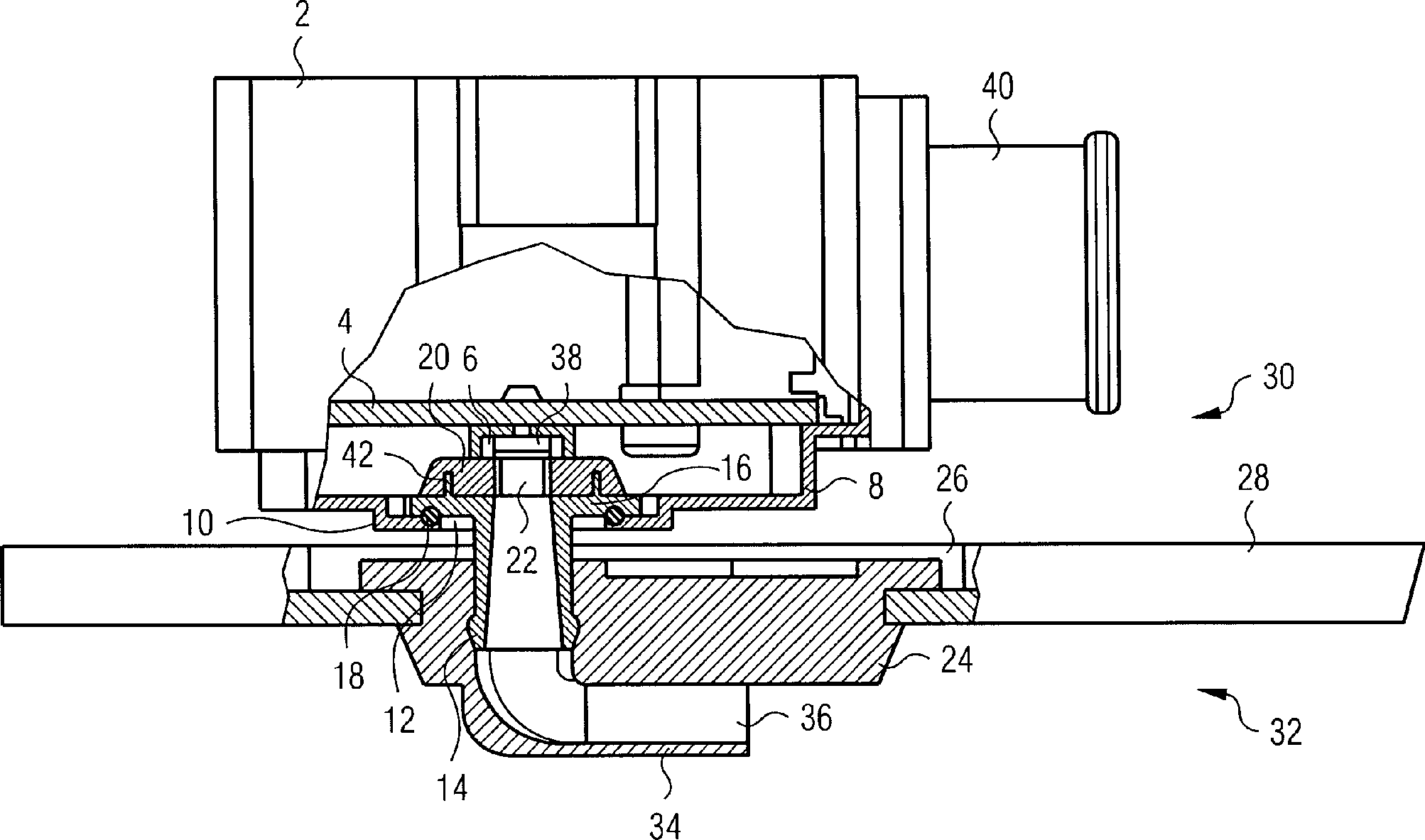
Gemäß
Durch
die Öffnung
Das
von dem Ringflansch
Die
Wand
Der
Dichtkörper
Wenn
erforderlich, ist zwischen der druckempfindlichen Fläche des
Drucksensors
Die
Montage der beschriebenen Baugruppe ist wie folgt:
In dem Gehäuse
In the case
Die
Leiterplatte
Es
versteht sich, daß das
Gehäuse
Der
Dichtkörper
Im
Unterschied zur Ausführungsform
der
Die
Funktion und der Zusammenbau der Baugruppe gemäß
Die
Montage geschieht bei der Ausführungsform
gemäß
Bei
abgenommenen Deckel
With the lid removed
Bei
der Ausführungsform
gemäß
Zur
Montage der Baugruppe gemäß
Es
versteht sich, daß die
beschriebenen Ausführungsformen
nur beispielhaft sind und vielfältige
Abwandlungen möglich
sind, mit denen die druckempfindliche Fläche des Drucksensors
Claims (9)
Priority Applications (5)
| Application Number | Priority Date | Filing Date | Title |
|---|---|---|---|
| DE19923985A DE19923985B4 (en) | 1999-05-25 | 1999-05-25 | Sensor assembly with a wall mountable housing |
| PCT/DE2000/001686 WO2000071978A1 (en) | 1999-05-25 | 2000-05-25 | Sensor module with a housing that can be mounted on a wall |
| DE50014895T DE50014895D1 (en) | 1999-05-25 | 2000-05-25 | SENSOR ASSEMBLY WITH A HOUSING MOUNTABLE ON A WALL |
| EP00943640A EP1181505B8 (en) | 1999-05-25 | 2000-05-25 | Sensor module with a housing that can be mounted on a wall |
| US09/994,204 US6647793B2 (en) | 1999-05-25 | 2001-11-26 | Sensor module having a housing which can be fitted on a wall |
Applications Claiming Priority (1)
| Application Number | Priority Date | Filing Date | Title |
|---|---|---|---|
| DE19923985A DE19923985B4 (en) | 1999-05-25 | 1999-05-25 | Sensor assembly with a wall mountable housing |
Publications (2)
| Publication Number | Publication Date |
|---|---|
| DE19923985A1 DE19923985A1 (en) | 2000-12-21 |
| DE19923985B4 true DE19923985B4 (en) | 2006-12-28 |
Family
ID=7909159
Family Applications (2)
| Application Number | Title | Priority Date | Filing Date |
|---|---|---|---|
| DE19923985A Expired - Fee Related DE19923985B4 (en) | 1999-05-25 | 1999-05-25 | Sensor assembly with a wall mountable housing |
| DE50014895T Expired - Fee Related DE50014895D1 (en) | 1999-05-25 | 2000-05-25 | SENSOR ASSEMBLY WITH A HOUSING MOUNTABLE ON A WALL |
Family Applications After (1)
| Application Number | Title | Priority Date | Filing Date |
|---|---|---|---|
| DE50014895T Expired - Fee Related DE50014895D1 (en) | 1999-05-25 | 2000-05-25 | SENSOR ASSEMBLY WITH A HOUSING MOUNTABLE ON A WALL |
Country Status (4)
| Country | Link |
|---|---|
| US (1) | US6647793B2 (en) |
| EP (1) | EP1181505B8 (en) |
| DE (2) | DE19923985B4 (en) |
| WO (1) | WO2000071978A1 (en) |
Cited By (2)
| Publication number | Priority date | Publication date | Assignee | Title |
|---|---|---|---|---|
| DE102007055114A1 (en) * | 2007-11-19 | 2009-05-20 | Volkswagen Ag | Method for securely attaching a sensor to a motor vehicle and correspondingly designed sensor and motor vehicle |
| DE102013114140A1 (en) * | 2013-12-16 | 2015-06-18 | Endress + Hauser Wetzer Gmbh + Co. Kg | Sensor housing and sensor arrangement with a sensor housing |
Families Citing this family (50)
| Publication number | Priority date | Publication date | Assignee | Title |
|---|---|---|---|---|
| DE10106311B4 (en) * | 2001-02-12 | 2006-06-22 | Siemens Ag | Device for attachment to a vehicle door |
| AUPR806801A0 (en) * | 2001-10-03 | 2001-10-25 | Davey Products Pty Ltd | Pump control system |
| DE10226258A1 (en) * | 2002-06-13 | 2003-12-24 | Bosch Gmbh Robert | sensor |
| DE20215283U1 (en) * | 2002-10-04 | 2003-11-13 | Brose Fahrzeugteile | Vehicle unit has sensor for pressure or pressure change caused by vehicle part deformation sending signal to control restraining unit |
| DE10333964A1 (en) * | 2003-07-25 | 2005-02-24 | Robert Bosch Gmbh | Cover for the housing of a sensor assembly with a pressure sensor |
| JP2006300774A (en) * | 2005-04-21 | 2006-11-02 | Denso Corp | Diaphragm type pressure detecting device |
| JP2006315525A (en) * | 2005-05-12 | 2006-11-24 | Denso Corp | Pressure sensor for collision detection |
| JP2007064837A (en) * | 2005-08-31 | 2007-03-15 | Denso Corp | Pressure sensor |
| JP2007078461A (en) | 2005-09-13 | 2007-03-29 | Denso Corp | Pressure sensor |
| DE102005048396A1 (en) * | 2005-10-10 | 2007-04-19 | Siemens Ag | sensor assembly |
| JP2007114001A (en) * | 2005-10-19 | 2007-05-10 | Denso Corp | Pressure sensor |
| JP4591306B2 (en) * | 2005-10-19 | 2010-12-01 | 株式会社デンソー | Collision detection system |
| DE102005053014B4 (en) * | 2005-11-07 | 2009-09-24 | Continental Automotive Gmbh | Pressure sensor housing and method for its manufacture |
| DE102006023464B4 (en) * | 2006-05-18 | 2010-04-15 | Continental Automotive Gmbh | Sensor assembly with a wall mountable housing |
| DE102006043323A1 (en) | 2006-09-15 | 2008-03-27 | Robert Bosch Gmbh | Pressure sensor for side impact sensing and method of forming a surface of a protective material for a pressure sensor |
| DE102006047397B4 (en) | 2006-10-06 | 2019-07-04 | Robert Bosch Gmbh | Air pressure sensor for a crash detection |
| US20090145249A1 (en) * | 2006-10-20 | 2009-06-11 | Dubbeldam Arthur J | Modular scanner assembly |
| DE102006057468A1 (en) * | 2006-12-06 | 2008-06-26 | Hydac Electronic Gmbh | Device for determining a state variable of a device to be examined |
| DE102006058301B4 (en) * | 2006-12-11 | 2016-12-29 | Robert Bosch Gmbh | Air pressure sensor for side impact detection |
| DE102007008862A1 (en) | 2007-02-23 | 2008-08-28 | Robert Bosch Gmbh | crash sensor |
| DE102007009692A1 (en) | 2007-02-28 | 2008-09-04 | Robert Bosch Gmbh | Accident sensor has fastening medium for fastening accident sensor to wall in vehicle, and hole is provided, which has bolt in elastically designed sleeve as fastening medium |
| DE102007009697A1 (en) | 2007-02-28 | 2008-09-04 | Robert Bosch Gmbh | Air-pressure sensor for sensing vehicle side impact, has fixing unit with structure in region of pressure inlet channel that runs through opening in vehicle door, where structure permits air-pressure sensor to be hooked onto vehicle wall |
| JP4375460B2 (en) * | 2007-08-08 | 2009-12-02 | 株式会社デンソー | Pressure sensor |
| US7981182B2 (en) * | 2007-12-31 | 2011-07-19 | Honda Motor Co., Ltd. | Labyrinth box structure and method |
| DE102008001393A1 (en) * | 2008-04-25 | 2009-10-29 | Robert Bosch Gmbh | Air pressure sensor for impact detection |
| DE102008040155A1 (en) * | 2008-07-03 | 2010-01-07 | Robert Bosch Gmbh | Sensor housing cover and method of making such a sensor housing cover |
| JP5179295B2 (en) * | 2008-08-27 | 2013-04-10 | 株式会社パイオラックス | Temperature sensor mounting device |
| DE102008048318A1 (en) | 2008-09-22 | 2010-09-23 | Audi Ag | Fastening device and method for fastening in an opening in a wall |
| CA2707540C (en) * | 2009-06-26 | 2016-06-21 | Jireh Industries Ltd. | Modular scanner apparatus and probe holding apparatus for inspection |
| DE102010020959A1 (en) * | 2010-04-30 | 2011-11-03 | Continental Automotive Gmbh | Fastening device for fastening an assembly in an opening of a wall of a vehicle |
| DE102010020961A1 (en) * | 2010-04-30 | 2011-11-03 | Continental Automotive Gmbh | Method and fastening device for fastening an assembly in an opening of a wall of a vehicle |
| DE112013003234T5 (en) * | 2012-06-26 | 2015-05-07 | Halla Visteon Climate Control Corporation | Infrared sensor arrangement for measuring the temperature in a motor vehicle |
| DE102012106142B4 (en) | 2012-07-09 | 2022-08-04 | Continental Automotive Gmbh | Fastening device for fastening an assembly in an opening in a wall of a vehicle |
| DE102012106733A1 (en) | 2012-07-24 | 2014-01-30 | Continental Automotive Gmbh | Fastening device for fixing component in opening of wall of vehicle, comprises molding provided towards wall, on which support lug contacts wall in inserted state into wall, where interference fit is formed between support lug and wall |
| DE102013208541A1 (en) * | 2012-12-27 | 2014-07-03 | Robert Bosch Gmbh | Detection device and method for producing a detection device |
| DE102013208534A1 (en) * | 2012-12-27 | 2014-07-03 | Robert Bosch Gmbh | Method for producing a sensor housing and corresponding sensor housing |
| DE102013213481A1 (en) | 2013-07-10 | 2015-01-15 | Continental Automotive Gmbh | Pressure sensor assembly with straight contacts and arranged perpendicular to the wall circuit carrier |
| DE102013213482A1 (en) * | 2013-07-10 | 2015-01-29 | Continental Automotive Gmbh | Pressure sensor assembly with labyrinth seal |
| US10663931B2 (en) | 2013-09-24 | 2020-05-26 | Rosemount Inc. | Process variable transmitter with dual compartment housing |
| US9642273B2 (en) * | 2013-09-25 | 2017-05-02 | Rosemount Inc. | Industrial process field device with humidity-sealed electronics module |
| CN115014412A (en) | 2013-09-30 | 2022-09-06 | 罗斯蒙特公司 | Process variable transmitter with dual compartment housing |
| US9260071B2 (en) | 2014-03-11 | 2016-02-16 | Trw Automotive U.S. Llc | Apparatus for snap mounting a crash sensor |
| JP2015184100A (en) * | 2014-03-24 | 2015-10-22 | セイコーエプソン株式会社 | Physical quantity sensor, manufacturing method of the same, pressure sensor, altimeter, electronic apparatus, and mobile body |
| US9470595B2 (en) * | 2014-08-29 | 2016-10-18 | Trw Automotive U.S. Llc | Apparatus for dry side mounting a crash pressure sensor |
| FR3027387B1 (en) | 2014-10-16 | 2018-02-16 | Senstronic | SENSOR DEVICE WITH MODULAR CONSTITUTION AND INDUSTRIAL EQUIPMENT COMPRISING SAME |
| DE102015101112B4 (en) * | 2015-01-27 | 2018-05-09 | Tdk Corporation | sensor |
| US10139707B2 (en) | 2015-01-28 | 2018-11-27 | Trw Automotive U.S. Llc | Camera bracket |
| JP6498965B2 (en) * | 2015-02-27 | 2019-04-10 | パナソニック デバイスSunx株式会社 | Pressure sensor |
| US10015899B2 (en) | 2015-06-29 | 2018-07-03 | Rosemount Inc. | Terminal block with sealed interconnect system |
| DE102021205213A1 (en) | 2021-05-20 | 2022-11-24 | Continental Automotive Technologies GmbH | Impact sensor unit consisting of two pressure sensors in a common housing and motor vehicle with such an impact sensor unit |
Citations (4)
| Publication number | Priority date | Publication date | Assignee | Title |
|---|---|---|---|---|
| DE4447513A1 (en) * | 1994-07-28 | 1996-02-01 | Siemens Ag | Watertight housing for protection of vehicle PCB electronic circuits |
| DE19737821A1 (en) * | 1996-08-30 | 1998-03-05 | Denso Corp | Flexible component for mounting sensor with its ground section at sensor reception |
| DE19718392A1 (en) * | 1997-04-30 | 1998-11-05 | Sick Ag | Housing component with rotatable section for reception of electrical cables |
| DE4442478C2 (en) * | 1993-11-30 | 1999-03-25 | Mitsubishi Electric Corp | Sensor with integrated connector |
Family Cites Families (4)
| Publication number | Priority date | Publication date | Assignee | Title |
|---|---|---|---|---|
| US5209495A (en) * | 1990-09-04 | 1993-05-11 | Palmour Harold H | Reciprocating rod pump seal assembly |
| US5386730A (en) * | 1992-06-25 | 1995-02-07 | Nippondenso Co., Ltd. | Pressure sensor having a sealed water-resistant construction |
| DE4426812A1 (en) * | 1994-07-28 | 1996-02-08 | Siemens Ag | Water-tight housing for electronic switching device |
| US5625156A (en) * | 1996-04-29 | 1997-04-29 | General Motors Corporation | Apparatus for sensing exhaust gas |
-
1999
- 1999-05-25 DE DE19923985A patent/DE19923985B4/en not_active Expired - Fee Related
-
2000
- 2000-05-25 DE DE50014895T patent/DE50014895D1/en not_active Expired - Fee Related
- 2000-05-25 EP EP00943640A patent/EP1181505B8/en not_active Expired - Lifetime
- 2000-05-25 WO PCT/DE2000/001686 patent/WO2000071978A1/en active IP Right Grant
-
2001
- 2001-11-26 US US09/994,204 patent/US6647793B2/en not_active Expired - Fee Related
Patent Citations (4)
| Publication number | Priority date | Publication date | Assignee | Title |
|---|---|---|---|---|
| DE4442478C2 (en) * | 1993-11-30 | 1999-03-25 | Mitsubishi Electric Corp | Sensor with integrated connector |
| DE4447513A1 (en) * | 1994-07-28 | 1996-02-01 | Siemens Ag | Watertight housing for protection of vehicle PCB electronic circuits |
| DE19737821A1 (en) * | 1996-08-30 | 1998-03-05 | Denso Corp | Flexible component for mounting sensor with its ground section at sensor reception |
| DE19718392A1 (en) * | 1997-04-30 | 1998-11-05 | Sick Ag | Housing component with rotatable section for reception of electrical cables |
Cited By (2)
| Publication number | Priority date | Publication date | Assignee | Title |
|---|---|---|---|---|
| DE102007055114A1 (en) * | 2007-11-19 | 2009-05-20 | Volkswagen Ag | Method for securely attaching a sensor to a motor vehicle and correspondingly designed sensor and motor vehicle |
| DE102013114140A1 (en) * | 2013-12-16 | 2015-06-18 | Endress + Hauser Wetzer Gmbh + Co. Kg | Sensor housing and sensor arrangement with a sensor housing |
Also Published As
| Publication number | Publication date |
|---|---|
| WO2000071978A1 (en) | 2000-11-30 |
| EP1181505B1 (en) | 2008-01-02 |
| US20020069700A1 (en) | 2002-06-13 |
| EP1181505B8 (en) | 2008-05-07 |
| EP1181505A1 (en) | 2002-02-27 |
| DE19923985A1 (en) | 2000-12-21 |
| US6647793B2 (en) | 2003-11-18 |
| DE50014895D1 (en) | 2008-02-14 |
Similar Documents
| Publication | Publication Date | Title |
|---|---|---|
| DE19923985B4 (en) | Sensor assembly with a wall mountable housing | |
| DE102006042680B4 (en) | pressure sensor | |
| DE19936300B4 (en) | Pressure detection device and pressure detection device arrangement hereby | |
| DE102005040844B4 (en) | Water resistant housing structure for electronic control device | |
| EP2025213B1 (en) | Sensor module with a housing which may be mounted on a wall | |
| DE112015003942T5 (en) | Device for mounting an impact pressure sensor on a dry side | |
| DE102006053114A1 (en) | Electronic circuit's i.e. controller circuit, housing, for vehicle i.e. motor vehicle, has pressure balancing element for balancing pressure of interior atmosphere of housing in relation to surroundings, arranged at plug connecting element | |
| EP0779170A2 (en) | Pollutant detector | |
| DE102005053014A1 (en) | Pressure sensor housing and method for its manufacture | |
| EP1969909B1 (en) | Control device module, especially in or for a motor vehicle | |
| DE102009026444A1 (en) | Control unit with pressure sensor | |
| WO2019228690A1 (en) | Charging station for charging an energy accumulator of a motor vehicle | |
| WO1993012562A1 (en) | Contact strip | |
| EP2862278B1 (en) | Approach detection device | |
| EP2186387B1 (en) | Housing for an electrical/electronic circuit | |
| EP2798921B1 (en) | Housing for receiving an electronic unit | |
| DE102005048396A1 (en) | sensor assembly | |
| DE10333964A1 (en) | Cover for the housing of a sensor assembly with a pressure sensor | |
| DE102013105788A1 (en) | Motor vehicle door outside handle | |
| DE10115153B4 (en) | Device for locking and unlocking a fuel filler flap, which closes a tank trough | |
| WO2008148652A2 (en) | Quick mount sensor housing for sensors with air contact | |
| EP1353160A1 (en) | Pressure sensor | |
| DE10057912A1 (en) | Electrical plug connector used in vehicle engine compartment, includes membrane vent admitting air, not water and pressure compensating element inserted in opening | |
| DE102005005897B3 (en) | Circuit module for gearshift control of motor vehicle, uses spray-on sealing substance to closely seal junction point between flexible PCB and contact element for protection against dirt or dust | |
| DE10216430C1 (en) | Fixing device attaching cladding panel to switchgear housing has screw fitted through aligned openings in opposing sides of cladding panel U-shaped edge and L-shaped edge of housing component |
Legal Events
| Date | Code | Title | Description |
|---|---|---|---|
| OP8 | Request for examination as to paragraph 44 patent law | ||
| 8364 | No opposition during term of opposition | ||
| 8327 | Change in the person/name/address of the patent owner |
Owner name: CONTINENTAL AUTOMOTIVE GMBH, 30165 HANNOVER, DE |
|
| 8339 | Ceased/non-payment of the annual fee |