JP4591306B2 - Collision detection system - Google Patents
Collision detection system Download PDFInfo
- Publication number
- JP4591306B2 JP4591306B2 JP2005304350A JP2005304350A JP4591306B2 JP 4591306 B2 JP4591306 B2 JP 4591306B2 JP 2005304350 A JP2005304350 A JP 2005304350A JP 2005304350 A JP2005304350 A JP 2005304350A JP 4591306 B2 JP4591306 B2 JP 4591306B2
- Authority
- JP
- Japan
- Prior art keywords
- pressure sensor
- vehicle
- detection system
- claw
- collision detection
- Prior art date
- Legal status (The legal status is an assumption and is not a legal conclusion. Google has not performed a legal analysis and makes no representation as to the accuracy of the status listed.)
- Expired - Fee Related
Links
- 238000001514 detection method Methods 0.000 title claims description 42
- 230000001133 acceleration Effects 0.000 claims description 4
- 239000004033 plastic Substances 0.000 claims description 3
- 210000000078 claw Anatomy 0.000 claims description 2
- 125000006850 spacer group Chemical group 0.000 description 6
- 239000000853 adhesive Substances 0.000 description 4
- 230000001070 adhesive effect Effects 0.000 description 4
- 239000002390 adhesive tape Substances 0.000 description 4
- 239000002184 metal Substances 0.000 description 4
- 238000000034 method Methods 0.000 description 3
- 241001247986 Calotropis procera Species 0.000 description 2
- 239000005357 flat glass Substances 0.000 description 2
- 230000035939 shock Effects 0.000 description 2
- 230000002238 attenuated effect Effects 0.000 description 1
- 238000013016 damping Methods 0.000 description 1
- 230000000694 effects Effects 0.000 description 1
- 239000013013 elastic material Substances 0.000 description 1
- 230000002093 peripheral effect Effects 0.000 description 1
Images


Classifications
-
- B—PERFORMING OPERATIONS; TRANSPORTING
- B60—VEHICLES IN GENERAL
- B60R—VEHICLES, VEHICLE FITTINGS, OR VEHICLE PARTS, NOT OTHERWISE PROVIDED FOR
- B60R21/00—Arrangements or fittings on vehicles for protecting or preventing injuries to occupants or pedestrians in case of accidents or other traffic risks
- B60R21/01—Electrical circuits for triggering passive safety arrangements, e.g. airbags, safety belt tighteners, in case of vehicle accidents or impending vehicle accidents
- B60R21/013—Electrical circuits for triggering passive safety arrangements, e.g. airbags, safety belt tighteners, in case of vehicle accidents or impending vehicle accidents including means for detecting collisions, impending collisions or roll-over
- B60R21/0136—Electrical circuits for triggering passive safety arrangements, e.g. airbags, safety belt tighteners, in case of vehicle accidents or impending vehicle accidents including means for detecting collisions, impending collisions or roll-over responsive to actual contact with an obstacle, e.g. to vehicle deformation, bumper displacement or bumper velocity relative to the vehicle
-
- B—PERFORMING OPERATIONS; TRANSPORTING
- B60—VEHICLES IN GENERAL
- B60R—VEHICLES, VEHICLE FITTINGS, OR VEHICLE PARTS, NOT OTHERWISE PROVIDED FOR
- B60R21/00—Arrangements or fittings on vehicles for protecting or preventing injuries to occupants or pedestrians in case of accidents or other traffic risks
- B60R21/01—Electrical circuits for triggering passive safety arrangements, e.g. airbags, safety belt tighteners, in case of vehicle accidents or impending vehicle accidents
- B60R2021/01006—Mounting of electrical components in vehicles
Description
本発明は、乗員保護装置等の作動・非作動を決定する衝突検知システムに関する。 The present invention relates to a collision detection system that determines operation / non-operation of an occupant protection device or the like.
車両には、衝突時に乗員を保護する乗員保護システムが搭載されている。乗員保護システムとしては、例えば、エアバッグを展開させることにより乗員の頭部を保護するエアバッグ装置や、シートベルトの弛みを巻き取るプリテンショナがある。このような乗員保護システムにおいて、エアバッグ装置やプリテンショナは制御装置(ECU)に制御される。ECUは、車両に設けられたセンサからの信号にもとづいて衝突の判定を行い、衝突と判定したときに動作させる。 The vehicle is equipped with an occupant protection system that protects the occupant during a collision. Examples of the occupant protection system include an airbag device that protects the occupant's head by deploying the airbag and a pretensioner that winds up slack in the seat belt. In such an occupant protection system, the airbag device and the pretensioner are controlled by a control device (ECU). The ECU determines a collision based on a signal from a sensor provided in the vehicle, and operates when it is determined as a collision.
近年の車両においては、車両の進行方向(前後方向)に対する衝突安全だけでなく、車両の側方から(幅方向)の衝突(側面衝突)に対する安全性も求められている。側面衝突に対して乗務員を保護するためのエアバッグ装置として、サイドエアバッグがある。サイドエアバッグを展開させるためのセンサには、車両のドアの内圧の変化を検出する圧力センサが用いられている。このようなサイドエアバッグ装置は、例えば、特許文献1に開示されている。
In recent vehicles, not only collision safety in the traveling direction (front-rear direction) of the vehicle but also safety against collision (side collision) from the side of the vehicle (width direction) is required. There is a side airbag as an airbag device for protecting a crew member against a side collision. As a sensor for deploying the side airbag, a pressure sensor that detects a change in the internal pressure of the door of the vehicle is used. Such a side airbag apparatus is disclosed by
衝突を検知するための圧力センサは、図10に示されるように、たとえば側面のドア2の密閉空間23における衝撃荷重などの圧力変動を検知するため、ドア2の内部の密閉空間23に取り付けられる。圧力センサは、図11及び図12に示されるように、圧力センサ3とドア2のインナーパネル21とに差し込まれたオネジ61とメネジ62とで固定される。
上記の圧力センサは、車両が悪路を走行したときに発生する振動や衝撃の加・減速度成分が圧力の検出部に伝達されてしまうことがある。特に、圧力センサがドアに強固に固定されている場合、ドアの強閉などにより発生する振動や衝撃が圧力の検出に影響を与える。 In the pressure sensor described above, vibration / shock acceleration / deceleration components generated when the vehicle travels on a rough road may be transmitted to the pressure detection unit. In particular, when the pressure sensor is firmly fixed to the door, vibrations and shocks generated by the strong closing of the door affect the pressure detection.
本発明は上記課題に鑑みてなされたもので、衝突以外の振動・衝撃の影響を受けにくい衝突検知システムを提供することを目的とする。 The present invention has been made in view of the above problems, and an object thereof is to provide a collision detection system that is not easily affected by vibrations and impacts other than collision.
本発明の衝突検知システムは、車両の外周部に閉鎖空間を形成する車両部材と該閉鎖空間内に保持された圧力センサとをもち、該車両が衝突したときに該車両部材の変形に伴う該閉鎖空間の容積の変化により生じる該閉鎖空間内の圧力の変化を該圧力センサで検知する衝突検知システムにおいて、
前記圧力センサは該圧力センサと前記車両部材との間に緩衝部材を介して保持されており、
前記緩衝部材は、前記圧力センサと前記車両部材とに挿入される軸部と、前記軸部の一端で前記車両部材とは反対方向の前記圧力センサの外側に位置する頭部と、前記軸部の他端で前記車両部材の車室側に位置する他端部と、前記車両部材及び前記圧力センサの間に爪状の板バネからなる爪状バネと、を有し、
前記圧力センサは、前記緩衝部材の前記頭部と前記他端部とで前記車両部材に保持されていることを特徴とする。
The collision detection system of the present invention has a vehicle member that forms a closed space on the outer periphery of a vehicle and a pressure sensor that is held in the closed space, and the vehicle member is deformed when the vehicle collides. In a collision detection system for detecting a change in pressure in the enclosed space caused by a change in volume of the enclosed space by the pressure sensor
The pressure sensor is held between the pressure sensor and the vehicle member via a buffer member,
The buffer member includes a shaft portion that is inserted into the pressure sensor and the vehicle member, a head portion that is positioned outside the pressure sensor in an opposite direction to the vehicle member at one end of the shaft portion, and the shaft portion. The other end of the other end of the vehicle member located on the vehicle compartment side, and a claw-shaped spring composed of a claw-shaped leaf spring between the vehicle member and the pressure sensor ,
The pressure sensor is held by the vehicle member at the head portion and the other end portion of the buffer member .
本発明の衝突検知システムでは、圧力センサが圧力センサと車両部材との間に緩衝部材を介して保持されることにより、緩衝部材が車両の衝突以外に車両部材に発生する振動や衝撃を吸収する。このため、車両部材に取り付けられた圧力センサには振動や衝撃が伝播しにくくなる。更に、圧力センサの検出部へ振動成分が伝播しにくくなるため、車両の閉鎖空間の圧力変動以外の振動や衝撃を圧力の変化として検出しにくくなる。 In the collision detection system of the present invention, the pressure sensor is held between the pressure sensor and the vehicle member via the buffer member, so that the buffer member absorbs vibration and impact generated in the vehicle member in addition to the vehicle collision. . For this reason, it is difficult for vibration and impact to propagate to the pressure sensor attached to the vehicle member. Furthermore, since it is difficult for vibration components to propagate to the detection part of the pressure sensor, it is difficult to detect vibrations and impacts other than pressure fluctuations in the closed space of the vehicle as changes in pressure.
本発明の衝突検知システムに用いられる緩衝部材は、ゴムブッシュまたはプラスチックであることが好ましい。緩衝部材にゴムブッシュやプラスチック等の弾性材料を使うことで、圧力センサが保持されている車両部材の振動や衝撃が緩衝部材に吸収され、圧力センサには大きな影響はない。 The buffer member used in the collision detection system of the present invention is preferably a rubber bush or plastic. By using an elastic material such as a rubber bush or plastic for the buffer member, the vibration and impact of the vehicle member holding the pressure sensor are absorbed by the buffer member, and the pressure sensor is not significantly affected.
本発明の衝突検知システムに用いられる緩衝部材は、爪状の板バネからなる爪状バネを有しており、圧力センサは圧力センサと車両部材とに挿入される軸部と軸部と圧力センサ及び車両部材との少なくとも一方間に設けられた爪状バネとにより保持されている。これにより、圧力センサは車両部材に工具不要で簡単にワンタッチで保持させることができ、その上、車両の衝突以外に車両部材に発生する振動や衝撃も吸収される。
本発明の衝突検知システムに用いられる緩衝部材の他端部は、爪状の板バネからなる小爪状バネであり、緩衝部材は車両部材を爪状バネと小爪状バネとで挟むことが好ましい。
本発明の衝突検知システムに用いられる緩衝部材の小爪状バネは、車両部材の貫通孔を通過する際は閉じる一方、通過後は爪状に広がって抜け止めをなすことが好ましい。
The shock-absorbing member used in the collision detection system of the present invention has a claw-shaped spring composed of a claw-shaped leaf spring, and the pressure sensor is inserted into the pressure sensor and the vehicle member, the shaft portion, the shaft portion, and the pressure sensor. And a claw-like spring provided between at least one of the vehicle member and the vehicle member. As a result, the pressure sensor can be easily held with one touch on the vehicle member without any tools, and vibrations and impacts generated on the vehicle member are also absorbed in addition to the collision of the vehicle.
The other end of the buffer member used in the collision detection system of the present invention is a small claw-shaped spring made of a claw-shaped leaf spring, and the buffer member can sandwich the vehicle member between the claw-shaped spring and the small claw-shaped spring. preferable.
The small claw-like spring of the buffer member used in the collision detection system of the present invention is preferably closed when passing through the through-hole of the vehicle member, but spreads in a claw-like shape after passing to prevent the spring.
本発明の衝突検知システムは、緩衝部材を介在させた場合の圧力センサの共振周波数が、車両部材上で発生する加・減速度周波数の1/10以下であることが好ましい。緩衝部材を介在させることにより、悪路走行及びドアの強閉時に車両部材上に発生する加・減速度周波数が圧力センサに1/10以下で伝播する。このため、圧力センサの共振レベルは、その減衰効果により、低くなり、更には、振動成分を圧力として検出するレベルが下がる。 In the collision detection system of the present invention, it is preferable that the resonance frequency of the pressure sensor when the buffer member is interposed is 1/10 or less of the acceleration / deceleration frequency generated on the vehicle member. By interposing the buffer member, the acceleration / deceleration frequency generated on the vehicle member when traveling on rough roads and when the door is strongly closed propagates to the pressure sensor at 1/10 or less. For this reason, the resonance level of the pressure sensor is lowered due to the damping effect, and further, the level at which the vibration component is detected as pressure is lowered.
本発明の衝突検知システムは、車両の外周部に形成されている閉鎖空間が車両の衝突で変形し、閉鎖空間の容積の変化により発生する圧力の変化を圧力センサで検知する。圧力センサは、車両の閉鎖空間内に閉鎖空間を形成する車両部材に緩衝部材を介して取り付けられる。車両が悪路を走行した場合や圧力センサが車両のドアに取り付けられ強閉した場合は、車両部材が振動し圧力センサに伝播してしまう。しかし、緩衝部材により振動成分をキャンセルあるいは抑えることにより圧力センサはその振動レベルが減衰され、車両の衝突時の振動や衝撃に伴う閉鎖空間の圧力変化以外を検出しにくくなる。 In the collision detection system of the present invention, a closed space formed in the outer periphery of the vehicle is deformed by the collision of the vehicle, and a change in pressure generated by a change in the volume of the closed space is detected by a pressure sensor. The pressure sensor is attached to a vehicle member that forms a closed space in the closed space of the vehicle via a buffer member. When the vehicle travels on a rough road or when the pressure sensor is attached to the door of the vehicle and closes tightly, the vehicle member vibrates and propagates to the pressure sensor. However, by canceling or suppressing the vibration component by the buffer member, the vibration level of the pressure sensor is attenuated, and it becomes difficult to detect other than the pressure change in the closed space due to the vibration or impact at the time of the collision of the vehicle.
本発明の衝突検知システムに用いられる緩衝部材は、圧力センサと車両部材との間に簡単に介在させることができ、圧力センサは狭い閉鎖空間であっても簡単に保持することができる。 The buffer member used in the collision detection system of the present invention can be easily interposed between the pressure sensor and the vehicle member, and the pressure sensor can be easily held even in a narrow closed space.
以下、実施例を用いて本発明を具体的に説明する。 Hereinafter, the present invention will be specifically described with reference to examples.
(実施例1)
本実施例1の衝突検知システムは、乗員保護装置の一部を構成することができ、より具体的には、側面衝突時に乗員を保護するサイドエアバッグを展開するための側面衝突を検知する。本実施例1の衝突検知システム1は、図1に示されているように、車両のドア2に設置される。
Example 1
The collision detection system of the first embodiment can constitute a part of the occupant protection device, and more specifically, detects a side collision for deploying a side airbag that protects the occupant during a side collision. The
車両のドア2は、車両の外周面の一部を形成するアウターパネル20と車両室内に面するインナーパネル21とウィンドガラス22とを有する。そして、アウターパネル20とインナーパネル21との間には、略密閉された閉鎖空間23が形成されている。この略密閉された閉鎖空間23は、ドア2の内部と外部とがわずかに連通して形成され、ドア2の外部の圧力が変化したときにはドア2の内部の空間23の圧力も変化するとともに、この空間23の内容積が急激に変化したときにはその内圧が上昇するように形成されている。
The
本実施例1の衝突検知システム1は、閉鎖空間23とインナーパネル21と圧力センサ3と緩衝部材4とを有する。
The
圧力センサ3は、閉鎖空間23内に緩衝部材4を介してインナーパネル21に取り付けられている。圧力センサ3はダイアフラム型の圧力センサよりなる。
The
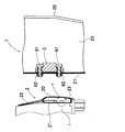
緩衝部材4は、図2及び図3に示されるように、圧力センサ3の両側の取り付け部30とインナーパネル21とに挿入される軸部40と、軸部40の一端でインナーパネル21とは反対方向の圧力センサ3の外側に位置する頭部41と、軸部40の他端でインナーパネル21の車室側に位置する小爪状バネ42(他端部)と、圧力センサ3とインナーパネル21との間にあり軸部40に一体形成されている大爪状バネ43(爪状バネ)と、大爪状バネ43と圧力センサ3との間にあるナット44とからなる。
As shown in FIGS. 2 and 3, the
小爪状バネ42は、取り付け部30及びインナーパネル21の内部を通過する際は、閉じられており、インナーパネル21を通過後は広がり、通過したインナーパネル21から抜けない形状で安定する。圧力センサ3は、頭部41と小爪状バネ42とでインナーパネル21に保持される。
The small claw-
大爪状バネ43は、小爪状バネ42とでインナーパネル21を挟み、圧力センサ3をインナーパネル21に固定させる。大爪状バネ43及び小爪状バネ42は、弾性力によりインナーパネル21が振動してもその振動や衝撃を吸収する。
The large claw-
緩衝部材4は、上記形状に限定されるものではなく、圧力センサ3をインナーパネル21に固定し、圧力センサ3とインナーパネル2との間で弾性力によりインナーパネル21の振動を吸収することができるものであれば良い。好ましいのは、緩衝部材4がワンタッチで圧力センサ3をインナーパネル21に固定することができ、弾性力をもつものである。
The
(参考例1)
本参考例1の衝突検知システムは、実施例1と同様、乗員保護装置の一部を構成することができ、より具体的には、側面衝突時に乗員を保護するサイドエアバッグを展開するための側面衝突を検知する。
( Reference Example 1 )
The collision detection system of this reference example 1 can constitute a part of the occupant protection device as in the first embodiment, and more specifically, for deploying a side airbag that protects the occupant during a side collision. Detect side collisions.
参考例1は、緩衝部材4の構成と圧力センサ3をインナーパネル21に取り付ける方法が実施例1とは異なるだけであり、それ以外は実施例1と同じ構成のものである。よって、特に言及しない部材については、実施例1と同様の部材であり、詳細な説明を省略する。
The reference example 1 is different from the first embodiment only in the configuration of the
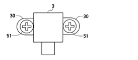
圧力センサ3は、図4及び図5に示すように、圧力センサ3の両側の取り付け部30とインナーパネル21とに挿入される軸部50と、軸部50の一端でインナーパネル21とは反対方向の圧力センサ3の外側に位置する頭部51と、軸部50の他端でインナーパネル21の車室側に位置するナット52とからなる金具5によりインナーパネル21に固定される。
As shown in FIGS. 4 and 5, the
緩衝部材4は、圧力センサ3とインナーパネル21とで挟まれる第1スペーサ45と、頭部51と圧力センサ3との間に位置する第2スペーサ46とを有する。第1スペーサ45及び第2スペーサ46とは、インナーパネル21が衝突以外の衝撃や振動を受けても吸収し、圧力センサ3に伝播するのを抑制することができる。
The
参考例1で利用される金具5は、従来の圧力センサ3を取り付けていた部材を利用することが可能であり、緩衝部材4を簡単に圧力センサ3との間に介在させることができる。
The
(参考例2)
本参考例2の衝突検知システムは、実施例1と同様、乗員保護装置の一部を構成することができ、より具体的には、側面衝突時に乗員を保護するサイドエアバッグを展開するための側面衝突を検知する。
( Reference Example 2 )
The collision detection system of the present reference example 2 can constitute a part of the occupant protection device as in the first embodiment, and more specifically, for deploying a side airbag that protects the occupant during a side collision. Detect side collisions.
参考例2は、緩衝部材4の構成と圧力センサ3をインナーパネル21に取り付ける方法が実施例1とは異なるだけであり、それ以外は実施例1と同じ構成のものである。よって、特に言及しない部材については、実施例1と同様の部材であり、詳細な説明を省略する。
The reference example 2 has the same configuration as that of the first embodiment except that the configuration of the
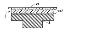
緩衝部材4は、図8及び図9に示されるように、ゴム弾性を持つ所定の厚さの一枚のシート状である。緩衝部材4は、両面に所定の大きさの粘着テープ48が貼り付けられ、緩衝部材4に貼り付けらた粘着テープ48の反対面をそれぞれ圧力センサ3及びインナーパネル21に貼り付ける。粘着テープ48は、緩衝部材4を介して圧力センサ3がインナーパネル21に十分に保持できるだけの粘着力と大きさであれば、緩衝部材4の全面に貼り付けるのではなく、例えば緩衝部材4の四辺に貼り付けても良い。
As shown in FIGS. 8 and 9, the
緩衝部材4は、上記に示された一枚のシート状に限定されるものではなく、弾性力を持つものであれば、2つ以上に分割されたもの、例えば圧力センサ3の両端あるいは上下に分割し接着されるものでも良い。そして、接着剤48も緩衝部材4の大きさに合わせた大きさであり、接着力が十分で圧力センサ3をインナーパネル21に保持できるものであれば良い。
The shock-absorbing
緩衝部材4は、インナーパネル21が衝突以外の衝撃や振動を受けても吸収し、圧力センサ3に伝播するのを抑制することができる。
The
(参考例3)
本参考例3の衝突検知システムは、実施例1と同様、乗員保護装置の一部を構成することができ、より具体的には、側面衝突時に乗員を保護するサイドエアバッグを展開するための側面衝突を検知する。
( Reference Example 3 )
As in the first embodiment, the collision detection system according to the third embodiment can constitute a part of the occupant protection device, and more specifically, for deploying a side airbag that protects the occupant during a side collision. Detect side collisions.
参考例3は、緩衝部材4の構成と圧力センサ3をインナーパネル21に取り付ける方法が実施例1とは異なるだけであり、それ以外は実施例1と同じ構成のものである。よって、特に言及しない部材については、実施例1と同様の部材であり、詳細な説明を省略する。
The reference example 3 has the same configuration as that of the first embodiment except that the configuration of the
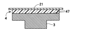
緩衝部材4は、図6及び図7に示されるように、ゴム弾性を持ち所定の厚さの一枚のシート状であり、対面する接着面47を持つ。圧力センサ3は接着面47の一方に接着され、他方の接着面47にインナーパネル21が接着され、緩衝部材4を介してインナーパネル21に保持される。
As shown in FIGS. 6 and 7, the
緩衝部材4は、インナーパネル21が衝突以外の衝撃や振動を受けても吸収し、圧力センサ3に伝播するのを抑制することができる。緩衝部材4は、上記に示された一枚のシート状に限定されるものではなく、圧力センサ3をインナーパネル21に固定することができ弾性力を持つものであれば、2つ以上に分割されたもの、つまり圧力センサ3の両端あるいは上下に分割して接着されるものでも良い。
The
以上、本発明の好適な実施例及び参考例について説明したが、本発明は上記実施例に限定されるものではない。例えば、圧力センサ3を固定する箇所が1箇所でも2箇所以上でも可能であり、車両の閉鎖空間23内に設置することができれば良い。
As mentioned above, although the suitable Example and reference example of this invention were described, this invention is not limited to the said Example. For example, the position where the
1:衝突検知システム
2:ドア
20:アウターパネル 21:インナーパネル
22:ウィンドガラス 23:閉鎖空間
3:圧力センサ
30:取り付け部
4:緩衝部材
40,50:軸部 41,51:頭部
42:小爪状バネ 43:大爪状バネ
44,52:ナット 45:第1スペーサ
46:第2スペーサ 47:接着面
48:粘着テープ
5:金具
60:金属ブッシュ 61:オネジ
62:メネジ
1: Collision detection system 2: Door 20: Outer panel 21: Inner panel 22: Window glass 23: Closed space 3: Pressure sensor 30: Mounting portion 4:
Claims (6)
前記圧力センサは該圧力センサと前記車両部材との間に緩衝部材を介して保持されており、
前記緩衝部材は、前記圧力センサと前記車両部材とに挿入される軸部と、前記軸部の一端で前記車両部材とは反対方向の前記圧力センサの外側に位置する頭部と、前記軸部の他端で前記車両部材の車室側に位置する他端部と、前記車両部材及び前記圧力センサの間に爪状の板バネからなる爪状バネと、を有し、
前記圧力センサは、前記緩衝部材の前記頭部と前記他端部とで前記車両部材に保持されていることを特徴とする衝突検知システム。 It has a vehicle member that forms a closed space in the outer periphery of the vehicle and a pressure sensor held in the closed space, and is generated by a change in volume of the closed space due to deformation of the vehicle member when the vehicle collides. In a collision detection system that detects a change in pressure in the enclosed space with the pressure sensor,
The pressure sensor is held between the pressure sensor and the vehicle member via a buffer member,
The buffer member includes a shaft portion that is inserted into the pressure sensor and the vehicle member, a head portion that is positioned outside the pressure sensor in an opposite direction to the vehicle member at one end of the shaft portion, and the shaft portion. The other end of the other end of the vehicle member located on the vehicle compartment side, and a claw-shaped spring formed of a claw-shaped leaf spring between the vehicle member and the pressure sensor ,
The said pressure sensor is hold | maintained at the said vehicle member by the said head and the said other end part of the said buffer member, The collision detection system characterized by the above-mentioned .
前記緩衝部材は、前記車両部材を爪状バネと小爪状バネとで挟む請求項1又は2に記載の衝突検知システム。 The collision detection system according to claim 1, wherein the buffer member sandwiches the vehicle member between a claw-shaped spring and a small claw-shaped spring.
前記爪状バネは、前記軸部に一体形成されている請求項1〜5の何れかに記載の衝突検知システム。The collision detection system according to claim 1, wherein the claw-shaped spring is integrally formed with the shaft portion.
Priority Applications (3)
| Application Number | Priority Date | Filing Date | Title |
|---|---|---|---|
| JP2005304350A JP4591306B2 (en) | 2005-10-19 | 2005-10-19 | Collision detection system |
| US11/581,710 US20070084663A1 (en) | 2005-10-19 | 2006-10-16 | Mounting structure of collision detection apparatus |
| DE102006049115A DE102006049115B4 (en) | 2005-10-19 | 2006-10-18 | Mounting construction for a collision detection device |
Applications Claiming Priority (1)
| Application Number | Priority Date | Filing Date | Title |
|---|---|---|---|
| JP2005304350A JP4591306B2 (en) | 2005-10-19 | 2005-10-19 | Collision detection system |
Publications (2)
| Publication Number | Publication Date |
|---|---|
| JP2007112241A JP2007112241A (en) | 2007-05-10 |
| JP4591306B2 true JP4591306B2 (en) | 2010-12-01 |
Family
ID=37913019
Family Applications (1)
| Application Number | Title | Priority Date | Filing Date |
|---|---|---|---|
| JP2005304350A Expired - Fee Related JP4591306B2 (en) | 2005-10-19 | 2005-10-19 | Collision detection system |
Country Status (3)
| Country | Link |
|---|---|
| US (1) | US20070084663A1 (en) |
| JP (1) | JP4591306B2 (en) |
| DE (1) | DE102006049115B4 (en) |
Families Citing this family (7)
| Publication number | Priority date | Publication date | Assignee | Title |
|---|---|---|---|---|
| DE202006016033U1 (en) * | 2006-05-17 | 2007-01-11 | Montaplast Gmbh | System protecting pedestrian in case of collision with vehicle, comprises vertical extension located at engine cover |
| JP2009300364A (en) * | 2008-06-17 | 2009-12-24 | Denso Corp | Side-impact detecting apparatus |
| DE102012017843A1 (en) * | 2012-02-25 | 2013-08-29 | Brose Fahrzeugteile Gmbh & Co. Kommanditgesellschaft, Hallstadt | Carrier for mounting electric or electronic component on motor vehicle, comprises a base structure which is flexibly adaptable to a space of motor vehicle, and one or more holding elements for mounting electric or electronic component |
| JP5888313B2 (en) * | 2013-12-13 | 2016-03-22 | 株式会社デンソー | Vehicle side collision detection device |
| DE102014225025A1 (en) * | 2014-12-05 | 2016-06-09 | Robert Bosch Gmbh | Component holder and component for a vehicle |
| CN108072576B (en) * | 2017-11-29 | 2020-05-08 | 重庆北金人防工程设备有限公司 | Civil air defense door testing device and manufacturing method thereof |
| CN108663077B (en) * | 2018-05-08 | 2021-07-09 | 陈卓琦 | Vehicle sensor device installed on track |
Citations (9)
| Publication number | Priority date | Publication date | Assignee | Title |
|---|---|---|---|---|
| JPH07508950A (en) * | 1992-11-11 | 1995-10-05 | シーメンス アクチエンゲゼルシヤフト | Control unit for vehicle occupant protection systems |
| JPH0814295A (en) * | 1994-06-27 | 1996-01-16 | Bridgestone Corp | Bush |
| JPH08324379A (en) * | 1995-05-30 | 1996-12-10 | Toyota Motor Corp | Side impact detecting device for vehicle |
| JPH10122914A (en) * | 1996-08-30 | 1998-05-15 | Denso Corp | Sensor mounting elastic member, sensor mounting structure using it and sensor mounting method |
| JP2000146512A (en) * | 1998-11-09 | 2000-05-26 | Toyota Motor Corp | Rotation detector |
| JP2003294978A (en) * | 2002-03-29 | 2003-10-15 | Okano Electric Wire Co Ltd | Fused fiber type optical coupler |
| JP2004101217A (en) * | 2002-09-05 | 2004-04-02 | Denso Corp | Mounting structure of sensor apparatus |
| JP2004132462A (en) * | 2002-10-10 | 2004-04-30 | Bridgestone Corp | Mounting structure for ea material |
| JP2005014646A (en) * | 2003-06-23 | 2005-01-20 | Honda Motor Co Ltd | Mounting structure of tire pneumatic sensing device |
Family Cites Families (22)
| Publication number | Priority date | Publication date | Assignee | Title |
|---|---|---|---|---|
| US3154281A (en) * | 1962-02-20 | 1964-10-27 | Frank Charles | Holder for electronic components |
| US3191135A (en) * | 1963-04-15 | 1965-06-22 | Honeywell Inc | Self-mounting electrical apparatus |
| US4687164A (en) * | 1983-12-01 | 1987-08-18 | Mechanical Products, Inc. | Snap-in bushing |
| US4681288A (en) * | 1985-09-04 | 1987-07-21 | Shinagawa Shoko Co., Ltd. | Fixing component |
| JP2987153B2 (en) * | 1989-03-24 | 1999-12-06 | マツダ株式会社 | Energy absorption structure on the side of the vehicle |
| JP2829132B2 (en) * | 1990-12-21 | 1998-11-25 | 北川工業株式会社 | Fixture |
| DE4307434A1 (en) * | 1993-03-09 | 1994-09-15 | United Carr Gmbh Trw | Holding element made of plastic |
| BR9608062A (en) * | 1995-04-28 | 1999-11-30 | Rosemount Inc | Mounting set for a pressure sensor on a pressure transmitter, and, process for connecting a pressure transmitter holder. |
| CN1066606C (en) * | 1995-08-21 | 2001-05-30 | 日幸工业株式会社 | Electrical parts retainer and fixing mechanism |
| US5921510A (en) * | 1996-11-21 | 1999-07-13 | Avery Dennison Corp. | Cable tie with christmas tree fastener |
| DE19811613B4 (en) * | 1998-03-17 | 2007-01-25 | Bayerische Motoren Werke Ag | Arrangement of a sensor in a vehicle |
| DE19830752C2 (en) * | 1998-07-09 | 2003-10-16 | Itw Ateco Gmbh | mounting clip |
| DE19923985B4 (en) * | 1999-05-25 | 2006-12-28 | Siemens Ag | Sensor assembly with a wall mountable housing |
| US6572317B2 (en) * | 2000-09-14 | 2003-06-03 | Piolax Inc. | Resilient fastener clip |
| US6719513B1 (en) * | 2000-09-19 | 2004-04-13 | Ford Global Technologies, Llc | Reverse bow retention push pin |
| US6496372B1 (en) * | 2001-09-26 | 2002-12-17 | Intel Corporation | Heat sink fastener for an electronic device |
| JP2004150949A (en) * | 2002-10-30 | 2004-05-27 | Denso Corp | Elastic member for attaching sensor, and sensor device using the same |
| JP2005042770A (en) * | 2003-07-24 | 2005-02-17 | Sumitomo Wiring Syst Ltd | Locking structure of clamp |
| DE10351146B4 (en) * | 2003-11-03 | 2007-05-10 | Bayerische Motoren Werke Ag | Fastening device for an acceleration-dependent sensor assembly in motor vehicles |
| US8028962B2 (en) * | 2004-04-30 | 2011-10-04 | Hellermanntyton Corporation | Fir tree mount for cable ties |
| JP2006300774A (en) * | 2005-04-21 | 2006-11-02 | Denso Corp | Diaphragm type pressure detecting device |
| US7503528B2 (en) * | 2006-08-11 | 2009-03-17 | Panduit Corp. | Cable mount |
-
2005
- 2005-10-19 JP JP2005304350A patent/JP4591306B2/en not_active Expired - Fee Related
-
2006
- 2006-10-16 US US11/581,710 patent/US20070084663A1/en not_active Abandoned
- 2006-10-18 DE DE102006049115A patent/DE102006049115B4/en not_active Expired - Fee Related
Patent Citations (9)
| Publication number | Priority date | Publication date | Assignee | Title |
|---|---|---|---|---|
| JPH07508950A (en) * | 1992-11-11 | 1995-10-05 | シーメンス アクチエンゲゼルシヤフト | Control unit for vehicle occupant protection systems |
| JPH0814295A (en) * | 1994-06-27 | 1996-01-16 | Bridgestone Corp | Bush |
| JPH08324379A (en) * | 1995-05-30 | 1996-12-10 | Toyota Motor Corp | Side impact detecting device for vehicle |
| JPH10122914A (en) * | 1996-08-30 | 1998-05-15 | Denso Corp | Sensor mounting elastic member, sensor mounting structure using it and sensor mounting method |
| JP2000146512A (en) * | 1998-11-09 | 2000-05-26 | Toyota Motor Corp | Rotation detector |
| JP2003294978A (en) * | 2002-03-29 | 2003-10-15 | Okano Electric Wire Co Ltd | Fused fiber type optical coupler |
| JP2004101217A (en) * | 2002-09-05 | 2004-04-02 | Denso Corp | Mounting structure of sensor apparatus |
| JP2004132462A (en) * | 2002-10-10 | 2004-04-30 | Bridgestone Corp | Mounting structure for ea material |
| JP2005014646A (en) * | 2003-06-23 | 2005-01-20 | Honda Motor Co Ltd | Mounting structure of tire pneumatic sensing device |
Also Published As
| Publication number | Publication date |
|---|---|
| DE102006049115A1 (en) | 2007-05-03 |
| US20070084663A1 (en) | 2007-04-19 |
| JP2007112241A (en) | 2007-05-10 |
| DE102006049115B4 (en) | 2012-04-26 |
Similar Documents
| Publication | Publication Date | Title |
|---|---|---|
| JP4591306B2 (en) | Collision detection system | |
| CN108698549B (en) | Collision detection device for vehicle | |
| JP4852940B2 (en) | Collision detection system | |
| JP3553617B2 (en) | Shock detector | |
| US8350685B2 (en) | Collision detecting device | |
| JP6162317B2 (en) | Compression sensor packaging method | |
| US20100042296A1 (en) | Method and device for triggering a personal protection means for a vehicle | |
| JP6042305B2 (en) | Vehicle collision determination device | |
| JP2005351898A (en) | Compound impact sensor | |
| JP5962435B2 (en) | Bumper for vehicle equipped with pedestrian collision detection device | |
| JP4479629B2 (en) | Collision detection system | |
| JP3972937B2 (en) | Shock absorption pad mounting structure for automobiles | |
| US8473188B2 (en) | Vehicle collision detecting system | |
| JP2016165977A (en) | Collision detection device | |
| EP2234846B1 (en) | A vehicle sensor system | |
| US20050066724A1 (en) | Acceleration sensor unit | |
| JP6512692B2 (en) | Collision detection device | |
| KR100398240B1 (en) | door structure for a automotive vehicle | |
| JPH09277832A (en) | Door structure for vehicle | |
| JP2007331637A (en) | Interior component for automobile | |
| JP2010083158A (en) | Airbag sensor mounting structure | |
| KR101593404B1 (en) | Assembly device of air bag | |
| JP2006056470A (en) | Windshield mounting part structure | |
| JP6485246B2 (en) | Vehicle door | |
| KR100187362B1 (en) | Structure for reinforcing the lower part of rear door of a car |
Legal Events
| Date | Code | Title | Description |
|---|---|---|---|
| A621 | Written request for application examination |
Free format text: JAPANESE INTERMEDIATE CODE: A621 Effective date: 20071102 |
|
| A977 | Report on retrieval |
Free format text: JAPANESE INTERMEDIATE CODE: A971007 Effective date: 20100224 |
|
| A131 | Notification of reasons for refusal |
Free format text: JAPANESE INTERMEDIATE CODE: A131 Effective date: 20100304 |
|
| A521 | Request for written amendment filed |
Free format text: JAPANESE INTERMEDIATE CODE: A523 Effective date: 20100428 |
|
| A131 | Notification of reasons for refusal |
Free format text: JAPANESE INTERMEDIATE CODE: A131 Effective date: 20100601 |
|
| A521 | Request for written amendment filed |
Free format text: JAPANESE INTERMEDIATE CODE: A523 Effective date: 20100720 |
|
| TRDD | Decision of grant or rejection written | ||
| A01 | Written decision to grant a patent or to grant a registration (utility model) |
Free format text: JAPANESE INTERMEDIATE CODE: A01 Effective date: 20100817 |
|
| A01 | Written decision to grant a patent or to grant a registration (utility model) |
Free format text: JAPANESE INTERMEDIATE CODE: A01 |
|
| A61 | First payment of annual fees (during grant procedure) |
Free format text: JAPANESE INTERMEDIATE CODE: A61 Effective date: 20100830 |
|
| FPAY | Renewal fee payment (event date is renewal date of database) |
Free format text: PAYMENT UNTIL: 20130924 Year of fee payment: 3 |
|
| R151 | Written notification of patent or utility model registration |
Ref document number: 4591306 Country of ref document: JP Free format text: JAPANESE INTERMEDIATE CODE: R151 |
|
| FPAY | Renewal fee payment (event date is renewal date of database) |
Free format text: PAYMENT UNTIL: 20130924 Year of fee payment: 3 |
|
| R250 | Receipt of annual fees |
Free format text: JAPANESE INTERMEDIATE CODE: R250 |
|
| R250 | Receipt of annual fees |
Free format text: JAPANESE INTERMEDIATE CODE: R250 |
|
| R250 | Receipt of annual fees |
Free format text: JAPANESE INTERMEDIATE CODE: R250 |
|
| R250 | Receipt of annual fees |
Free format text: JAPANESE INTERMEDIATE CODE: R250 |
|
| R250 | Receipt of annual fees |
Free format text: JAPANESE INTERMEDIATE CODE: R250 |
|
| R250 | Receipt of annual fees |
Free format text: JAPANESE INTERMEDIATE CODE: R250 |
|
| R250 | Receipt of annual fees |
Free format text: JAPANESE INTERMEDIATE CODE: R250 |
|
| LAPS | Cancellation because of no payment of annual fees |