JP5448872B2 - Fuel system for direct injection internal combustion engine - Google Patents
Fuel system for direct injection internal combustion engine Download PDFInfo
- Publication number
- JP5448872B2 JP5448872B2 JP2010010544A JP2010010544A JP5448872B2 JP 5448872 B2 JP5448872 B2 JP 5448872B2 JP 2010010544 A JP2010010544 A JP 2010010544A JP 2010010544 A JP2010010544 A JP 2010010544A JP 5448872 B2 JP5448872 B2 JP 5448872B2
- Authority
- JP
- Japan
- Prior art keywords
- fuel rail
- fuel
- clamp
- internal combustion
- direct injection
- Prior art date
- Legal status (The legal status is an assumption and is not a legal conclusion. Google has not performed a legal analysis and makes no representation as to the accuracy of the status listed.)
- Active
Links
Images


Classifications
-
- F—MECHANICAL ENGINEERING; LIGHTING; HEATING; WEAPONS; BLASTING
- F02—COMBUSTION ENGINES; HOT-GAS OR COMBUSTION-PRODUCT ENGINE PLANTS
- F02M—SUPPLYING COMBUSTION ENGINES IN GENERAL WITH COMBUSTIBLE MIXTURES OR CONSTITUENTS THEREOF
- F02M55/00—Fuel-injection apparatus characterised by their fuel conduits or their venting means; Arrangements of conduits between fuel tank and pump F02M37/00
- F02M55/02—Conduits between injection pumps and injectors, e.g. conduits between pump and common-rail or conduits between common-rail and injectors
- F02M55/025—Common rails
-
- F—MECHANICAL ENGINEERING; LIGHTING; HEATING; WEAPONS; BLASTING
- F02—COMBUSTION ENGINES; HOT-GAS OR COMBUSTION-PRODUCT ENGINE PLANTS
- F02M—SUPPLYING COMBUSTION ENGINES IN GENERAL WITH COMBUSTIBLE MIXTURES OR CONSTITUENTS THEREOF
- F02M63/00—Other fuel-injection apparatus having pertinent characteristics not provided for in groups F02M39/00 - F02M57/00 or F02M67/00; Details, component parts, or accessories of fuel-injection apparatus, not provided for in, or of interest apart from, the apparatus of groups F02M39/00 - F02M61/00 or F02M67/00; Combination of fuel pump with other devices, e.g. lubricating oil pump
- F02M63/02—Fuel-injection apparatus having several injectors fed by a common pumping element, or having several pumping elements feeding a common injector; Fuel-injection apparatus having provisions for cutting-out pumps, pumping elements, or injectors; Fuel-injection apparatus having provisions for variably interconnecting pumping elements and injectors alternatively
- F02M63/0225—Fuel-injection apparatus having a common rail feeding several injectors ; Means for varying pressure in common rails; Pumps feeding common rails
- F02M63/0275—Arrangement of common rails
- F02M63/0285—Arrangement of common rails having more than one common rail
-
- F—MECHANICAL ENGINEERING; LIGHTING; HEATING; WEAPONS; BLASTING
- F02—COMBUSTION ENGINES; HOT-GAS OR COMBUSTION-PRODUCT ENGINE PLANTS
- F02M—SUPPLYING COMBUSTION ENGINES IN GENERAL WITH COMBUSTIBLE MIXTURES OR CONSTITUENTS THEREOF
- F02M2200/00—Details of fuel-injection apparatus, not otherwise provided for
- F02M2200/30—Fuel-injection apparatus having mechanical parts, the movement of which is damped
- F02M2200/306—Fuel-injection apparatus having mechanical parts, the movement of which is damped using mechanical means
Description
本発明は直噴内燃エンジンに関し、特に内燃室に燃料を供給する燃料システムの構成部品に加わる応力を低減する直噴内燃エンジンの燃料システムに関するものである。 The present invention relates to a direct injection internal combustion engine, and more particularly to a fuel system for a direct injection internal combustion engine that reduces stress applied to components of the fuel system that supplies fuel to an internal combustion chamber.
自動車産業において直噴内燃エンジンは一般的になりつつあるが、その大きな原因は直噴内燃エンジンの効率が高く燃費が良いことによる。直噴内燃エンジンは、エンジンブロック内において、内燃室に直接開口する穴に少なくとも1つの燃料噴射器が取り付けられている。燃料噴射器には高圧燃料レールが連結されており、エンジン制御装置の制御により高圧燃料レールが開かれると燃料を直噴内燃エンジン内へ直接噴射するようになっている。 Direct injection internal combustion engines are becoming common in the automobile industry, but the major cause is that the efficiency of direct injection internal combustion engines is high and fuel consumption is good. In a direct injection internal combustion engine, at least one fuel injector is attached to a hole that directly opens into an internal combustion chamber in an engine block. A high pressure fuel rail is connected to the fuel injector, and when the high pressure fuel rail is opened under the control of the engine control device, fuel is directly injected into the direct injection internal combustion engine.
直噴内燃エンジンでは上記のように燃料噴射器が内燃室へ直接開口しているため、燃料レールの燃料を比較的高い圧力で維持しなければならない。従って、通常はカム駆動ピストンポンプ等の加圧ポンプを使用して燃料レール内部を加圧する。 In a direct injection internal combustion engine, since the fuel injector opens directly to the internal combustion chamber as described above, the fuel on the fuel rail must be maintained at a relatively high pressure. Therefore, normally, the inside of the fuel rail is pressurized using a pressurizing pump such as a cam drive piston pump.
しかし、直噴内燃エンジンは燃料噴射器や加圧ポンプが高圧で振動するため、燃料システムの構成部品が互いに連動して運動するという欠点がある。このため燃料システムの構成部品へ応力が次々に伝わり、亀裂やその他の構成部品の不具合が生じる可能性がある。 However, the direct-injection internal combustion engine has a drawback that the components of the fuel system move in conjunction with each other because the fuel injector and the pressure pump vibrate at high pressure. For this reason, stress is successively transmitted to the components of the fuel system, which may cause cracks and other component failures.
従来、これら振動を防ぐために、例えば特許文献1に示すように、燃料噴射器をシリンダハウジングに所定締め付け荷重で取付けるという構成が知られている。
Conventionally, in order to prevent these vibrations, for example, as shown in
しかし、特許文献1に示す構成によっても、発生する振動を十分に抑制することは困難であった。本発明は直噴燃料エンジンにおける燃料レールの運動を減らし、それによってそれら構成部品への機械的応力を低減する直噴内燃エンジンの燃料システムおよび応力低減装置を提供するものである。
However, even with the configuration shown in
本発明では燃料システムにおける燃料レールの運動を減らすために幾つかの異なる構成を提案している。本発明の一実施例では、隣り合う燃料レールの両方にクランプを伸ばして固定している。それらのレールを共にクランプで固定することにより、燃料システムのその他の構成部品に連動したレールの運動が低減される。また、燃料レールはクランプで堅固に固定してもよいが、エラストマー部材を用いて共に弾性的に固定してもよい。 The present invention proposes several different configurations to reduce fuel rail motion in the fuel system. In one embodiment of the invention, clamps are extended and secured to both adjacent fuel rails. By clamping the rails together, the rail motion associated with the other components of the fuel system is reduced. The fuel rail may be firmly fixed by a clamp, but may be elastically fixed together using an elastomer member.
本発明の別の実施例では、弾性部材を用いて運動質量を燃料レールに取り付けている。このため、運動質量の運動がレールのあらゆる運動に対抗し、よって燃料システムの作動中にレールの運動が効果的に打ち消される。 In another embodiment of the invention, the kinetic mass is attached to the fuel rail using an elastic member. Thus, the motion of the kinetic mass counteracts any motion of the rail and thus effectively cancels the motion of the rail during operation of the fuel system.
本発明の更に別の実施例では、可塑性のある流体管で燃料レールを燃料噴射器に接続している。この可塑性のある流体管によって、燃料噴射器の運動に起因する燃料レールの運動を低減もしくは、完全に抑制している。 In yet another embodiment of the invention, the fuel rail is connected to the fuel injector by a plastic fluid line. By this plastic fluid pipe, the movement of the fuel rail caused by the movement of the fuel injector is reduced or completely suppressed.
本発明は、少なくとも2つの燃料レールを有する直噴内燃エンジンにおいて、第1燃料レール及び第2燃料レールの一端に配置されたクランプに弾性部材を介して設けられた運動質量を有することにより、前記直噴内燃エンジンに連動した前記燃料レールの運動を低減することができる。
また、第1燃料レール及び第2燃料レールの一端に渡って固定され、第1燃料レール及び第2燃料レールの一端にそれぞれ嵌合する凹部を有する剛体からなるクランプにより、簡潔な構成で確実にクランプを燃料レールに固定することができる。
In the direct injection internal combustion engine having at least two fuel rails, the present invention has a moving mass provided via an elastic member on a clamp disposed at one end of the first fuel rail and the second fuel rail. The movement of the fuel rail in conjunction with the direct injection internal combustion engine can be reduced.
In addition, the clamp is made of a rigid body that is fixed over one end of the first fuel rail and the second fuel rail, and has a concave portion that fits to one end of each of the first fuel rail and the second fuel rail. The clamp can be fixed to the fuel rail.
図1には従来技術の直噴内燃エンジン20の一部が示されている。エンジン20には複数のエンジン燃焼室24を有するエンジンブロック22があり、エンジン燃焼室24にはピストン(図示せず)が相互に取り付けられている。
FIG. 1 shows a portion of a prior art direct injection
各燃焼室24には少なくとも1つの燃料噴射器26が設けられている。各燃料噴射器26は、エンジンブロック22内に設けられ、燃焼室24に開口する燃料噴射器穴28内に配置される。さらに各燃料噴射器26は、燃料レール室32を有する燃料レール30に流体的に連結されている。高圧燃料ポンプ(図示せず)によって加圧燃料が燃料レール室32に供給され、次々に燃料噴射器26に供給される。また、図1に示す燃料噴射器は、燃料レール30が互いに2つ並んで配置されたV型エンジン用の燃料噴射器である。
Each
一般的に燃料噴射器26は、燃料レール30に堅固に固定されている。燃料が噴射される度に燃料噴射器26が反動で燃焼室24から離れる方向に若干運動し、それによって、連関する燃料レール30が同方向に運動する。燃料レール30が上記のように運動すると、燃料システムの構成部品に次々に機械的応力が加わる。上記の運動は連続的に反復して発生し実質的に振動が発生する。
In general, the
図2および図3には本発明の実施例1が示されている。エンジンブロックに連動した燃料レール30の運動を減らすために、V字形のクランプ40を各燃料レール30間に伸ばし、止め具42で各燃料レール30に取り付けている。クランプ40を燃料レール30に固定するには、どのような止め具42を用いてもよい。あるいは、クランプ40は溶接や類似の方法で燃料レール30に固定して取り付けてもよい。
2 and 3
また、弾性部材46を用いて運動質量44をクランプ40に固定する。弾性部材46によって運動質量44がクランプ40と連動して運動し、従って燃料レール30と連動して運動する。弾性部材46はそれ自体弾性をもつゴム、プラスチック、バネ等を用いる。
Further, the moving
本発明において運動質量とは、運動する物体に取付けられて弾性部材を介して、運動する物体の運動速度や加速度を抑制する動的なおもりをいう。 In the present invention, the moving mass refers to a dynamic weight that is attached to a moving object and suppresses the moving speed and acceleration of the moving object via an elastic member.
作動中の燃料噴射器26から燃料レール30に運動が伝わると、運動質量44が共に運動し、燃料レール30の運動が効果的に打ち消される。さらに、クランプ40は単体でも内燃エンジンの作動中に燃料レール30の運動を低減する。
When motion is transferred from the
図2および図3には燃料レール30が2つ表示されているが、運動質量44はもちろん各燃料レール毎に使用してもよい。そのようなシステムでは、運動質量44によってエンジン作動中の各燃料レールの運動がより効果的に低減されまたは打ち消される。
Although two
図4および図5には、本発明の実施例2が示されている。ここではクランプ50を両方の燃料レール30の周囲に伸ばし、各燃料レール30を共に固定して運動に対抗させている。クランプ50はどのような形状でもよいが、図示のクランプ50には上部クランプ52および下部クランプ54があり、それらを合わせて燃料レール30を取り囲むようにしている。これらの上部クランプ52および下部クランプ54は止め具56で共に固定されているが、止め具56はボルトとナットのような従来のいかなる止め具でもよい。
4 and 5 show a second embodiment of the present invention. Here, the
実際上、クランプ50は燃料レール30を共に堅固に固定することによって燃料レール30の運動を減らし、またその運動で生じる燃料システムの構成部品への機械的応力を低減している。
In effect, the
図6および図7には、本発明の実施例3が示されている。ここではバンド状クランプ60の一端62が、はんだ付けなどの従来方法で一方の燃料レール30に堅固に固定されている。更にバンド状クランプ60の他端64が他方の燃料レール30に止め具66で固定され、止め具66と燃料レール30の間にはエラストマー部材68が挟まれている。エラストマー部材68によって燃料レール30の運動や振動が抑制される。
6 and 7 show a third embodiment of the present invention. Here, one
図8および図9には本発明の実施例4が図示されている。ここでは細長い管状のゴム等からなるエラストマー部材70を2つの燃料レール30の間に伸ばしている。止め具72でエラストマー部材70の一端を一方の燃料レール30に固定し、第2の止め具74でエラストマー部材70の他端を他方の燃料レール30に固定する。例えば、止め具72はエラストマー部材70を貫通するボルトで構成してもよく、第2の止め具74は止め具72を螺合するナットで構成してもよい。また、止め具72は各燃料レール30に取り付けられたボルトストップ76を貫通している。
8 and 9 show a fourth embodiment of the present invention. Here, an
実際上、エラストマー部材70は図9の矢印78で示す横方向への燃料レール30の振動を抑制する。燃料レール30の互いに連動する相対運動を抑制することにより、エラストマー部材70は燃料レール30の運動を効果的に減らし、同じくその運動から生じる構成部品への応力を低減する。
Actually, the
図10から図12には本発明の実施例5が示されている。ここでは剛体からなる上部クランプ82および下部クランプ84を有するクランプ80を用いて燃料レール30の運動を最小化している。上部クランプ82および下部クランプ84は、燃料レール30の端部88の一部に対応する形状の凹部86をそれぞれ有する。
10 to 12 show a fifth embodiment of the present invention. Here, the movement of the
したがって、図10および図12で良く分かるように、燃料レール30の端部88の周囲に上部クランプ82および下部クランプ84を配置した状態で、止め具90で燃料レール30の端部88の周囲に上部クランプ82および下部クランプ84を押し付けて、上部クランプ82および下部クランプ84を共に固定している。これにより、燃料レール30を共に堅固に固定して運動に対抗させ、よって燃料システムの構成部品への機械的応力を低減している。
Accordingly, as can be clearly seen in FIGS. 10 and 12, with the
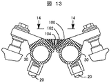
図13および図14には、本発明の実施例6が示されている。ここでは断面略V字型のクランプ100を両方の燃料レール30に延して固定している。クランプ100を燃料レール30に堅固に固定するには、止め具、はんだ、または同様のいかなる従来手段を用いてもよい。
A sixth embodiment of the present invention is shown in FIGS. Here, a
エラストマー部材102はゴム、プラスチック等の可撓性材料で構成することが望ましく、クランプ100の上部に渡って配置される。そして、エラストマー部材102が運動質量104とクランプ100の間に挟まれるように、運動質量104が弾性部材102の範囲内に配置される。
The
エラストマー部材102によって、エンジンの作動中に運動質量104が燃料レール30に連動して若干運動する。運動質量104はその運動でレール30の運動を抑制し、構成部品への応力を低減している。
The
図15および図16には、本発明の実施例7が示されている。ここでは可撓性をもつ流体管110を用いて、燃料噴射器26が燃料レール30に流体的に接続されている。流体管110は可撓性のベローズでもよいし、あるいは他の形状を用いてもよい。作動中、燃料噴射器26の燃料噴射に反応して燃料噴射器26が動いても、単に流体管110が曲がるに過ぎないため、燃料噴射器26の振動が燃料レール30から隔離される。これにより、燃料レール30の運動が皆無にはならないにせよ大きく低減され、燃料レール30の運動に起因する燃料システムの機械的応力が低減される。
15 and 16 show a seventh embodiment of the present invention. Here, the
また、図15および図16では燃料噴射器26は燃料レール30に堅固に接続されていないため、燃料噴射器26をエンジンブロック22に固定してその運動に対応させることが望ましい。燃料噴射器26をエンジンブロック22に固定するには様々な手段を利用できるが、図15に示すように、固定部材120がエンジンブロック22の外側に外部ねじ部125によりネジ止めされており、さらに固定部材120には半径方向に内部に突出したリブ122がある。
15 and 16, since the
固定部材120は非金属材料で構成し、燃料噴射器26とエンジンブロック22の間の金属間接触をなくして雑音を抑制することが望ましい。燃料噴射器26をエンジンブロックの燃料噴射器穴28内に配置すると、固定部材120のリブ122が燃料噴射器26の固定部材溝124と一致するようになっている。固定部材のリブ122と固定部材溝124の共同作用によって固定部材120に連動した燃料噴射器26の回転またはねじれ等の運動が抑制される。
The fixing
固定部材120をエンジンブロックに固定させるため、燃料噴射器穴28は内部ネジ部126を外端に有する。よって、固定部材120をエンジンブロック22にネジ止めで固定することにより、燃料噴射器26を簡単かつ効率的に固定して、エンジンブロック22に連動した軸方向運動に対抗させている。
In order to fix the fixing
あるいは、燃料噴射器26自体を非金属材料で構成してネジを設け、その燃料噴射器26に一体化された内部ネジ部126をエンジンブロック22に係合させることも可能である。
Alternatively, the
以上により、本発明はエンジンブロックに連動した燃料レールの運動を低減し、または完全に抑制する装置を幾つか提供する。これにより直噴内燃エンジンの作動中に、エンジンブロックに連動した燃料レールの運動から生じる燃料システムの構成部品への応力が大幅に減少する。 As described above, the present invention provides several devices that reduce or completely suppress the movement of the fuel rail in conjunction with the engine block. This greatly reduces the stress on the fuel system components resulting from the movement of the fuel rail in conjunction with the engine block during operation of the direct injection internal combustion engine.
また、本発明の特許請求の範囲から逸脱することなく、本発明に関する数多くの改良がなされることは、発明が属する技術分野の当業者において明らかである。 Also, it will be apparent to those skilled in the art to which the invention pertains that numerous modifications can be made to the invention without departing from the scope of the claims.
20:直噴内燃エンジン
26:燃料噴射器
28:燃料噴射器穴
44、104:運動質量
46:弾性部材
30:燃料レール
32:燃料室
40、50、80、100:クランプ
60:バンド状クランプ
70:エラストマー部材
110:流体管
120:固定部材
122:リブ
124:固定部材溝
125:外部ネジ部
126:内部ネジ部
20: direct injection internal combustion engine 26: fuel injector 28:
Claims (4)
前記エンジンブロックに取り付けられた第1燃料レール及び第2燃料レールと、前記エンジンブロックに連動した前記第1燃料レール及び第2燃料レールの運動を低減させる運動低減手段とを有し、前記運動低減手段は前記第1燃料レール及び第2燃料レールの少なくとも一部の周囲又は前記第1燃料レール及び第2燃料レールの一端に配置されたクランプを有し、前記クランプは前記第1燃料レール及び第2燃料レールに渡って延び、前記第1燃料レール及び第2燃料レールの周囲に堅固に固定され、前記クランプに弾性部材を介して設けられた運動質量を有することを特徴とする直噴内燃エンジンの応力低減装置。 In a stress reduction device for reducing mechanical stress applied to a fuel system of a direct injection internal combustion engine having an engine block,
Possess a first fuel rail and a second fuel rail attached to said engine block, and a motion reduction means for reducing the movement of the first fuel rail and a second fuel rail linked to the engine block, the motion reduction The means includes a clamp disposed around at least a portion of the first fuel rail and the second fuel rail or at one end of the first fuel rail and the second fuel rail, the clamp including the first fuel rail and the first fuel rail. A direct injection internal combustion engine having a moving mass extending over two fuel rails, firmly fixed around the first fuel rail and the second fuel rail, and provided to the clamp via an elastic member Stress reduction device.
前記エンジンブロックに取り付けられた第1燃料レール及び第2燃料レールと、前記エンジンブロックに連動した前記第1燃料レール及び第2燃料レールの運動を低減させる運動低減手段とを有し、前記運動低減手段は前記第1燃料レール及び第2燃料レールの少なくとも一部の周囲又は前記第1燃料レール及び第2燃料レールの一端に配置されたクランプを有し、前記第1燃料レール及び第2燃料レールは細長く互いに並んで配置されており、且つ、前記クランプは前記第1燃料レール及び第2燃料レールの一端にそれぞれ嵌合する凹部を有する剛体からなることを特徴とする直噴内燃エンジンの応力低減装置。 In a stress reduction device for reducing mechanical stress applied to a fuel system of a direct injection internal combustion engine having an engine block,
A first fuel rail and a second fuel rail attached to the engine block; and a motion reduction means for reducing the motion of the first fuel rail and the second fuel rail interlocked with the engine block. The means includes a clamp disposed around at least a portion of the first fuel rail and the second fuel rail or at one end of the first fuel rail and the second fuel rail , the first fuel rail and the second fuel rail. Are arranged side by side, and the clamp is made of a rigid body having a recess fitted to one end of each of the first fuel rail and the second fuel rail. apparatus.
Applications Claiming Priority (2)
| Application Number | Priority Date | Filing Date | Title |
|---|---|---|---|
| US12/414,151 | 2009-03-30 | ||
| US12/414,151 US7980226B2 (en) | 2009-03-30 | 2009-03-30 | Fuel system for a direct injection engine |
Publications (3)
| Publication Number | Publication Date |
|---|---|
| JP2010236535A JP2010236535A (en) | 2010-10-21 |
| JP2010236535A5 JP2010236535A5 (en) | 2012-10-04 |
| JP5448872B2 true JP5448872B2 (en) | 2014-03-19 |
Family
ID=42333447
Family Applications (1)
| Application Number | Title | Priority Date | Filing Date |
|---|---|---|---|
| JP2010010544A Active JP5448872B2 (en) | 2009-03-30 | 2010-01-21 | Fuel system for direct injection internal combustion engine |
Country Status (4)
| Country | Link |
|---|---|
| US (1) | US7980226B2 (en) |
| EP (1) | EP2236808B1 (en) |
| JP (1) | JP5448872B2 (en) |
| CN (1) | CN101852154B (en) |
Families Citing this family (6)
| Publication number | Priority date | Publication date | Assignee | Title |
|---|---|---|---|---|
| DE102012206931A1 (en) * | 2012-04-26 | 2013-10-31 | Robert Bosch Gmbh | Arrangement with a fuel distributor and a holder |
| DE102012206937A1 (en) * | 2012-04-26 | 2013-10-31 | Robert Bosch Gmbh | Arrangement with a fuel distributor and a holder |
| US9644753B2 (en) | 2013-07-17 | 2017-05-09 | Norgren Limited | Flapper exhaust diverter valve |
| US10220700B2 (en) * | 2015-02-09 | 2019-03-05 | Toyota Motor Engineering & Manufacturing North America, Inc. | Protection and support for vehicle engine components |
| US10208723B2 (en) | 2016-05-25 | 2019-02-19 | Hi-Vol Products | Threaded fuel rails |
| CN107524520B (en) * | 2017-08-18 | 2022-05-03 | 奇瑞汽车股份有限公司 | Noise reduction structure of oil sprayer |
Family Cites Families (29)
| Publication number | Priority date | Publication date | Assignee | Title |
|---|---|---|---|---|
| JPS51146514U (en) * | 1975-05-20 | 1976-11-25 | ||
| DE2829057A1 (en) | 1978-07-01 | 1980-01-10 | Bosch Gmbh Robert | FUEL INJECTION SYSTEM |
| JPS6034562U (en) * | 1983-08-17 | 1985-03-09 | 三菱重工業株式会社 | pipe clamp |
| JPS63115572U (en) * | 1987-01-21 | 1988-07-26 | ||
| US4766405A (en) * | 1987-04-14 | 1988-08-23 | Allied Corporation | Dynamic energy absorber |
| JPH0188065U (en) * | 1987-12-03 | 1989-06-09 | ||
| US4878650A (en) * | 1988-04-29 | 1989-11-07 | Allied-Signal Inc. | Armature with shear stress damper |
| JPH01176750U (en) * | 1988-06-02 | 1989-12-18 | ||
| DE4310408C1 (en) | 1993-03-31 | 1994-06-09 | Freudenberg Carl Fa | Fuel supply for multi-cylinder internal combustion engine - involves fuel quantity distributor with tubular distributor housing, fuel forward feed connection and fuel back flow connection |
| JP4194002B2 (en) * | 1998-05-13 | 2008-12-10 | ヤマハマリン株式会社 | In-cylinder fuel injection engine |
| US6009856A (en) * | 1998-05-27 | 2000-01-04 | Caterpillar Inc. | Fuel injector isolation |
| US6409102B1 (en) * | 1999-03-15 | 2002-06-25 | Aerosance, Inc. | Fuel injector assembly |
| AT4632U1 (en) * | 2000-05-25 | 2001-09-25 | Avl List Gmbh | INJECTION SYSTEM FOR AN INTERNAL COMBUSTION ENGINE |
| JP4428607B2 (en) * | 2000-10-25 | 2010-03-10 | 臼井国際産業株式会社 | Fuel injection pipe for common rail diesel engine |
| JP4240835B2 (en) * | 2001-03-29 | 2009-03-18 | 株式会社日本自動車部品総合研究所 | Fuel injection device for internal combustion engine |
| US6901964B2 (en) * | 2001-03-30 | 2005-06-07 | Saturn Electronics & Engineering, Inc. | Vehicle fuel pulse damper |
| JP4006956B2 (en) * | 2001-05-24 | 2007-11-14 | 日産自動車株式会社 | Fuel piping structure of V-type engine |
| DE10157010A1 (en) * | 2001-11-21 | 2003-06-05 | Bosch Gmbh Robert | fuel injection system |
| JP4152294B2 (en) * | 2003-10-22 | 2008-09-17 | 臼井国際産業株式会社 | Fuel delivery pipe |
| FR2861433B1 (en) * | 2003-10-24 | 2007-08-24 | Renault Sa | PRESSURIZED FUEL INJECTION DEVICE HAVING ANTI-VIBRATION MEANS |
| FR2875863B1 (en) * | 2004-09-30 | 2009-05-01 | Peugeot Citroen Automobiles Sa | INJECTION DEVICE WITH REDUCED ACCOUSTIC RADIATION |
| US7028688B1 (en) * | 2005-04-05 | 2006-04-18 | The United States Of America As Represented By The Secretary Of The Army | Operationally adaptable chemical-biological mask |
| DE102005029842A1 (en) * | 2005-06-27 | 2007-01-04 | Robert Bosch Gmbh | Fuel storage of a fuel injection system of a motor vehicle |
| US7293550B2 (en) * | 2006-01-31 | 2007-11-13 | Gm Global Technology Operations, Inc. | Fuel injector isolation seat |
| ATE416308T1 (en) * | 2006-03-23 | 2008-12-15 | Delphi Tech Inc | FASTENING ARRANGEMENT FOR AN INJECTOR |
| US7334571B1 (en) * | 2006-08-31 | 2008-02-26 | Gm Global Technology Operations, Inc. | Isolation system for high pressure spark ignition direct injection fuel delivery components |
| FR2909420B1 (en) * | 2006-11-30 | 2012-01-27 | Renault Sas | BARRIER DAMPING THE VIBRATION OF INJECTION PIPES ON AN INTERNAL COMBUSTION ENGINE |
| US7406946B1 (en) * | 2007-04-02 | 2008-08-05 | Hitachi, Ltd. | Method and apparatus for attenuating fuel pump noise in a direct injection internal combustion chamber |
| US7793639B2 (en) * | 2008-09-25 | 2010-09-14 | Hitachi, Ltd. | Apparatus for reducing the transmission for noise from the fuel rail in a direct injection engine |
-
2009
- 2009-03-30 US US12/414,151 patent/US7980226B2/en active Active
-
2010
- 2010-01-21 JP JP2010010544A patent/JP5448872B2/en active Active
- 2010-02-08 CN CN201010113789.3A patent/CN101852154B/en active Active
- 2010-02-17 EP EP10153878.3A patent/EP2236808B1/en active Active
Also Published As
| Publication number | Publication date |
|---|---|
| CN101852154A (en) | 2010-10-06 |
| CN101852154B (en) | 2013-05-01 |
| EP2236808B1 (en) | 2014-11-12 |
| EP2236808A3 (en) | 2011-03-09 |
| US20100242916A1 (en) | 2010-09-30 |
| EP2236808A2 (en) | 2010-10-06 |
| US7980226B2 (en) | 2011-07-19 |
| JP2010236535A (en) | 2010-10-21 |
Similar Documents
| Publication | Publication Date | Title |
|---|---|---|
| JP5448872B2 (en) | Fuel system for direct injection internal combustion engine | |
| JP5426899B2 (en) | Vibration propagation reducing device for fuel rail in direct injection internal combustion engine | |
| US8875681B2 (en) | Fuel rail mounting arrangement | |
| KR102075333B1 (en) | Holder for securing a component to an internal combustion engine | |
| JP2008132846A (en) | Engine mount structure | |
| US8844502B2 (en) | Fuel rail mount | |
| US10612507B2 (en) | Mounting structure of fuel rail | |
| KR102074655B1 (en) | Retainer for mounting a fuel distributor on an internal combustion engine and fuel injection system with such a retainer | |
| JP4724614B2 (en) | Vibration isolator | |
| JP5811760B2 (en) | Fuel pump mounting structure | |
| JP2001221127A (en) | Fuel injection system for internal combustion engine | |
| JP4235017B2 (en) | Anti-vibration rubber and anti-vibration device | |
| JP2015068219A (en) | Engine fuel injection device | |
| JP7464809B2 (en) | Fuel injection system | |
| JP2001227407A (en) | Mounting structure of common rail for internal combustion engine | |
| JP6466562B2 (en) | FUEL INJECTION DEVICE, SUSPENSION MEMBER, AND FUEL INJECTION SYSTEM HAVING THE SAME | |
| JP4671916B2 (en) | Vibration isolator | |
| JP2010121576A (en) | Supporting structure for fuel pump | |
| KR20240031707A (en) | Fuel rail cylinder head coupling structure | |
| KR20220012614A (en) | Fuel rail system | |
| KR101637780B1 (en) | Slip preventing coupling braket for multi stage turbo housing/cylinder block and engin exhaust structure for vehicle having the same | |
| JPH0755309Y2 (en) | Oil pan mounting structure | |
| US20150020517A1 (en) | High-pressure hose vibration suppressor | |
| CN110397516A (en) | Valve mechanism cover | |
| KR20090014888A (en) | Engine mount unit for vehicle |
Legal Events
| Date | Code | Title | Description |
|---|---|---|---|
| A521 | Request for written amendment filed |
Free format text: JAPANESE INTERMEDIATE CODE: A523 Effective date: 20120820 |
|
| A621 | Written request for application examination |
Free format text: JAPANESE INTERMEDIATE CODE: A621 Effective date: 20120820 |
|
| A977 | Report on retrieval |
Free format text: JAPANESE INTERMEDIATE CODE: A971007 Effective date: 20130828 |
|
| A131 | Notification of reasons for refusal |
Free format text: JAPANESE INTERMEDIATE CODE: A131 Effective date: 20130910 |
|
| A521 | Request for written amendment filed |
Free format text: JAPANESE INTERMEDIATE CODE: A523 Effective date: 20131106 |
|
| TRDD | Decision of grant or rejection written | ||
| A01 | Written decision to grant a patent or to grant a registration (utility model) |
Free format text: JAPANESE INTERMEDIATE CODE: A01 Effective date: 20131203 |
|
| A61 | First payment of annual fees (during grant procedure) |
Free format text: JAPANESE INTERMEDIATE CODE: A61 Effective date: 20131224 |
|
| R150 | Certificate of patent or registration of utility model |
Ref document number: 5448872 Country of ref document: JP Free format text: JAPANESE INTERMEDIATE CODE: R150 Free format text: JAPANESE INTERMEDIATE CODE: R150 |