JP5448233B2 - Package with liquid leakage prevention switch - Google Patents
Package with liquid leakage prevention switch Download PDFInfo
- Publication number
- JP5448233B2 JP5448233B2 JP2011527384A JP2011527384A JP5448233B2 JP 5448233 B2 JP5448233 B2 JP 5448233B2 JP 2011527384 A JP2011527384 A JP 2011527384A JP 2011527384 A JP2011527384 A JP 2011527384A JP 5448233 B2 JP5448233 B2 JP 5448233B2
- Authority
- JP
- Japan
- Prior art keywords
- package
- plate
- cover
- arm
- snap
- Prior art date
- Legal status (The legal status is an assumption and is not a legal conclusion. Google has not performed a legal analysis and makes no representation as to the accuracy of the status listed.)
- Expired - Fee Related
Links
Images


Classifications
-
- B—PERFORMING OPERATIONS; TRANSPORTING
- B65—CONVEYING; PACKING; STORING; HANDLING THIN OR FILAMENTARY MATERIAL
- B65D—CONTAINERS FOR STORAGE OR TRANSPORT OF ARTICLES OR MATERIALS, e.g. BAGS, BARRELS, BOTTLES, BOXES, CANS, CARTONS, CRATES, DRUMS, JARS, TANKS, HOPPERS, FORWARDING CONTAINERS; ACCESSORIES, CLOSURES, OR FITTINGS THEREFOR; PACKAGING ELEMENTS; PACKAGES
- B65D51/00—Closures not otherwise provided for
- B65D51/18—Arrangements of closures with protective outer cap-like covers or of two or more co-operating closures
-
- B—PERFORMING OPERATIONS; TRANSPORTING
- B65—CONVEYING; PACKING; STORING; HANDLING THIN OR FILAMENTARY MATERIAL
- B65D—CONTAINERS FOR STORAGE OR TRANSPORT OF ARTICLES OR MATERIALS, e.g. BAGS, BARRELS, BOTTLES, BOXES, CANS, CARTONS, CRATES, DRUMS, JARS, TANKS, HOPPERS, FORWARDING CONTAINERS; ACCESSORIES, CLOSURES, OR FITTINGS THEREFOR; PACKAGING ELEMENTS; PACKAGES
- B65D17/00—Rigid or semi-rigid containers specially constructed to be opened by cutting or piercing, or by tearing of frangible members or portions
- B65D17/50—Non-integral frangible members applied to, or inserted in, preformed openings, e.g. tearable strips or plastic plugs
- B65D17/506—Rigid or semi-rigid members, e.g. plugs
-
- B—PERFORMING OPERATIONS; TRANSPORTING
- B65—CONVEYING; PACKING; STORING; HANDLING THIN OR FILAMENTARY MATERIAL
- B65D—CONTAINERS FOR STORAGE OR TRANSPORT OF ARTICLES OR MATERIALS, e.g. BAGS, BARRELS, BOTTLES, BOXES, CANS, CARTONS, CRATES, DRUMS, JARS, TANKS, HOPPERS, FORWARDING CONTAINERS; ACCESSORIES, CLOSURES, OR FITTINGS THEREFOR; PACKAGING ELEMENTS; PACKAGES
- B65D2543/00—Lids or covers essentially for box-like containers
- B65D2543/00009—Details of lids or covers for rigid or semi-rigid containers
- B65D2543/00018—Overall construction of the lid
- B65D2543/00046—Drinking-through lids
-
- B—PERFORMING OPERATIONS; TRANSPORTING
- B65—CONVEYING; PACKING; STORING; HANDLING THIN OR FILAMENTARY MATERIAL
- B65D—CONTAINERS FOR STORAGE OR TRANSPORT OF ARTICLES OR MATERIALS, e.g. BAGS, BARRELS, BOTTLES, BOXES, CANS, CARTONS, CRATES, DRUMS, JARS, TANKS, HOPPERS, FORWARDING CONTAINERS; ACCESSORIES, CLOSURES, OR FITTINGS THEREFOR; PACKAGING ELEMENTS; PACKAGES
- B65D2543/00—Lids or covers essentially for box-like containers
- B65D2543/00009—Details of lids or covers for rigid or semi-rigid containers
- B65D2543/00018—Overall construction of the lid
- B65D2543/00259—Materials used
- B65D2543/00296—Plastic
Description
本発明は、実質的に平坦な平面壁を備えオリフィスを設けた消耗品用パッケージに関し、具体的にはこのようなパッケージ用の開閉具に関する。 The present invention relates to a consumable package having a substantially flat planar wall and provided with an orifice, and more particularly to an open / close device for such a package.
このようなパッケージは例えば金属缶であって、殆どの場合、2回圧延のスチール又はアルミニウムで作製され、液体飲料のような消耗品を収容するように構成された、実質的に円筒状の容器である。以下の説明において、「内側」及び「外側」とは、それぞれ、パッケージに向けられた部品の部分又はパッケージ内に位置する部品の部分と、パッケージに向けられた部品の部分又はパッケージ外に位置する部品の部分とを指す。金属缶は従来技術及び本発明におけるパッケージの一例として用いている。また液体飲料は消耗品の一例として用いている。 Such a package is, for example, a metal can, a substantially cylindrical container made of twice-rolled steel or aluminum and configured to contain consumables such as liquid beverages. It is. In the following description, “inside” and “outside” are respectively a part of a component directed to a package or a part of a component located in the package and a part of a component directed to the package or outside the package. Refers to parts. The metal can is used as an example of the package in the prior art and the present invention. Liquid beverages are used as an example of consumables.
金属缶の下端は閉塞されて、上面はカップとなっている。このカップの平坦部分は、蓋材と、蓋材の近傍に位置する取付位置によってカップに取り付けられている舌片とを備えている。この取付位置に対する梃子の運動を通じて舌片が蓋材を押圧して、事前に切り込みを入れた蓋材周縁のプレカット部分を破断させる。この切り込み部分が破断されると、蓋材がオリフィスを形成し、このオリフィスを通じて金属缶内の液体が、例えば消費のために流出可能となる。次に蓋材は金属缶内へ折り返されるが、カップ周縁の破断されていない部分によってカップに付着した状態で保持されている。 The lower end of the metal can is closed and the upper surface is a cup. The flat portion of the cup includes a lid member and a tongue piece attached to the cup by an attachment position located in the vicinity of the lid member. The tongue piece presses the lid material through the movement of the lever with respect to the attachment position, and the precut portion at the periphery of the lid material that has been cut in advance is broken. When the cut is broken, the lid forms an orifice through which the liquid in the metal can can flow, for example, for consumption. Next, the lid member is folded back into the metal can, but is held in a state where it is attached to the cup by an unbroken portion of the periphery of the cup.
このような金属缶の欠点は、金属缶が一旦開封されると再度閉塞できないことである。このため、金属缶が横転すると液体は金属缶から流出してしまう。また異物(虫、埃)がカップのオリフィスを通じて侵入することで液体を汚染させてしまう。さらにまた、液体がガスを含有するものであれば、数時間後には飲料内からガスが抜けてしまう。このような欠点のため、利用者は金属缶を開封したら直ぐに金属缶の内容物を全部使い切らざるを得なくなる。 The disadvantage of such a metal can is that once the metal can is opened, it cannot be closed again. For this reason, when the metal can rolls over, the liquid flows out of the metal can. In addition, foreign matters (insects, dust) enter through the orifices of the cup and contaminate the liquid. Furthermore, if the liquid contains gas, the gas will escape from the beverage after several hours. Due to such drawbacks, the user is forced to use up the entire contents of the metal can as soon as the metal can is opened.
一方でカップのリムに被せる樹脂製カバーが知られている。しかしながら、このようなカバーでは、金属缶からカップとカバー間の隙間へ液体が逃げてしまい、カバーを開けたときに不都合なことになる。またこのようなカバーは、ガス圧がカバーをカップから押し上げてしまうことがあるので、水密性が十分とは言えない。 On the other hand, a resin cover that covers the rim of the cup is known. However, with such a cover, the liquid escapes from the metal can to the gap between the cup and the cover, which is inconvenient when the cover is opened. Further, such a cover is not sufficiently watertight because the gas pressure may push the cover up from the cup.
また米国特許出願公開第2009/032531号明細書(特許文献1)に記載されるような回転型のカバーも知られている。この樹脂製カバーは金属缶のリム部分に被さり、カップの上面に対接して平坦にされ、金属缶の中心軸周りで旋回可能であり、蓋材を開封することにより作られたオリフィスを開閉するものである。しかしながら、いずれのカバーも水密性が十分とは言えない。 Also known is a rotary cover as described in US Patent Application Publication No. 2009/032531 (Patent Document 1). This resin cover covers the rim of the metal can, is flattened against the upper surface of the cup, can be rotated around the central axis of the metal can, and opens and closes the orifice made by opening the lid. Is. However, none of the covers is sufficiently watertight.
本発明の目的は、開閉具を備え、この開閉具によって開封され容易に再閉塞可能なパッケージであって、完全に水密性を有し、利用者が簡単に取り扱えるパッケージを提供することにある。 SUMMARY OF THE INVENTION An object of the present invention is to provide a package that includes an opening / closing tool, is openable by the opening / closing tool and can be easily re-closed, and is completely watertight and can be easily handled by a user.
上記目的は、実質的に平坦な平面壁を備え、かつオリフィスが設けられた消耗品用パッケージに開閉具を備えることで達成される。この開閉具は、成型材で作製され前記平面壁に固定された一体成型の本体部であって、前記オリフィスと対向して配置された孔が形成されており、平面壁の前記オリフィスの縁部に水密の態様で固定されたプレートを有する本体部と、パッケージの内部に向かって開口するこのプレートに連接され、前記孔を水密の態様で閉塞できる揚蓋と、を備えている。さらに開閉具は、前記揚蓋に連結されたアームであって、所定の位置でアームの移動を阻止する阻止手段と協働し、この阻止手段が前記揚蓋を水密の閉塞位置に維持し、アームが前記阻止手段から離れると揚蓋が前記パッケージの内部に向かって旋回して揚蓋を開放するアームを備えることを特徴とする。さらにまた開閉具は、前記本体部及び前記アームとは別個のカバーであって、前記揚蓋を初回に開封する際に必然的に破壊されるセキュリティ用蓋材を備えており、このセキュリティ用蓋材が破損していなければ、パッケージが事前に開封されていないことを保証でき、この蓋材は前記阻止手段の一部を形成し、前記カバーは前記プレートと連結するための手段を備え、前記カバーが前記プレートに連結されたとき前記パッケージの外部に位置しているので、前記平面壁の領域が前記カバーと前記プレート間に挟まれてなることを特徴とする。 The object is achieved by providing the opening / closing tool in a consumable package having a substantially flat plane wall and provided with an orifice. The opening / closing tool is an integrally molded main body portion made of a molding material and fixed to the planar wall, and has a hole disposed so as to face the orifice, and the edge of the orifice of the planar wall A main body having a plate fixed in a watertight manner, and a lifting lid connected to the plate that opens toward the inside of the package and capable of closing the hole in a watertight manner. Further closing member is an arm connected to said Agefuta cooperates with blocking means for preventing movement of the arm in place, maintaining the blocking means is the Agefuta watertight closed position, When the arm is separated from the blocking means, the lifting lid is provided with an arm that pivots toward the inside of the package and opens the lifting lid. Furthermore closing member, said the body portion and the arm be a separate cover is provided with a security lid material is necessarily destroyed upon opening the Agefuta the first time, the security lid If the material is not damaged, it can be assured that the package has not been pre-opened, this lid material forms part of the blocking means, and the cover comprises means for coupling with the plate, Since the cover is located outside the package when connected to the plate, the planar wall region is sandwiched between the cover and the plate.
これらの構成により、本パッケージは開封し、所望の回数だけ開閉できる。阻止手段によってアームが閉位置に停止されたままの状態であることで、揚蓋も水密な態様で閉塞される。 With these configurations, the package can be opened and opened and closed as many times as desired. Since the arm remains stopped at the closed position by the blocking means, the lifting lid is also closed in a watertight manner.
好適には、プレートはスナップロックすることによって平面壁におけるオリフィスの縁部に固定される。 Preferably, the plate is secured to the edge of the orifice in the planar wall by snap locking.
これにより、開閉具を平面壁に取り付けて固定することが特に容易となり、また密封性も強化される。 Accordingly, it is particularly easy to attach and fix the opening / closing tool to the flat wall, and the sealing performance is enhanced.
好適には、プレートは実質的に平面壁の内面に対接して支持される。 Preferably, the plate is supported substantially against the inner surface of the planar wall.
揚蓋をパッケージの内部に向かって開ける場合は、パッケージ内に僅かなガスが存在しても、揚蓋が閉位置にあるとき、この揚蓋を開閉具の本体部におけるプレートの内面に対してさらに押圧する方向に作用する。これによりガス漏れを防止し、パッケージの密封を確実にすることに貢献する。 When opening the lifting lid toward the inside of the package, even if there is a slight amount of gas in the package, when the lifting lid is in the closed position, the lifting lid is placed against the inner surface of the plate in the main body of the opening / closing tool. Furthermore, it acts in the pressing direction. This prevents gas leakage and contributes to ensuring the sealing of the package.
本発明は、以下の本発明を限定するものでない実施例で示す実施形態に関する詳細な説明から、良く理解でき、また本発明の利点がさらに明確なものとなるであろう。以下の添付図面を参照しながら説明する。 The invention will be better understood and the advantages of the invention will become more apparent from the detailed description of the embodiments given in the following non-limiting examples. This will be described with reference to the accompanying drawings.
以下に、金属缶に適用した例を参照しながら、本発明について説明する。ただ本発明は、実質的に平坦な平面壁を備え、かつオリフィスが設けられたパッケージであれば、他のものにも適用できる。 Below, this invention is demonstrated, referring the example applied to the metal can. However, the present invention can be applied to other packages as long as they have a substantially flat plane wall and are provided with orifices.
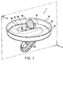
図1〜図4は、本発明に係る開閉具が金属缶(図示せず)のカップ10に載置されている状態を示している。このカップ10は実質的に円形であって、平面壁15は周縁リム12で包囲されている。カップにおける周縁リム12は、例えば金属缶の標準的なカップのリムと同一であり、開閉具1が取り付けられたカップ10は、あらゆる金属缶の製造過程で付加できる。カップ10の平面壁15は、内縁19で画成されたオリフィス13を設けている。このオリフィス13は楕円形とし、カップの中央からリム12近辺に半径方向に延在する。
1 to 4 show a state in which the opening / closing tool according to the present invention is placed on a
図1及び図2は、開閉具1が部分的に開位置にある状態を示している。開閉具1はプレート20を有する本体部2を備えており、このプレート20はプレート20の縁部25で画成された孔30を中央部に有する。本体部2は、図7及び図8にも示している。また本体部2は揚蓋40も備えており、本体部2と一体成型、すなわち揚蓋40がプレート20との連続体となっている。したがって、本体部2は一体成型で作製でき、これにより揚蓋40をプレート20とは個別に作製するよりも迅速かつ安価に利用できるという商業的な利点が得られる。本体部2は、例えばポリマーで作製される。
1 and 2 show a state in which the opening /
揚蓋40は可撓性を有するように成型された薄肉部41によってプレート20に連結され、プレート20の周囲に位置する。したがって、この薄肉部41はヒンジとなる。揚蓋40は周縁部47の底部42を備えており、この底部42の中央に円筒壁45が取り付けられる。
The lifting
揚蓋40が開位置にあるとき、この揚蓋40は金属缶内に入り込んでいる。
When the lifting
図4は揚蓋40が閉位置にある状態を示している。薄肉部41は完全に折り畳まれている。円筒壁45の半径方向における外面はプレート20の縁部25の半径方向における内面上に亘って閉じているので、円筒壁45は隙間無く実質的に孔30内に嵌入している。したがって、これにより密封性が得られ、金属缶内の液体を流出させないことに寄与している。
FIG. 4 shows a state where the lifting
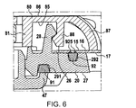
図5は図4の一部を拡大したものであり、揚蓋40とプレート20の嵌着状態を詳細に示している。このように嵌着しているとき、揚蓋40の周縁部47は孔30を取り囲むプレート20の金属缶の内部側へ指向する下面27に支えられている。これらの図に示すケースでは、実際には周縁部47は下面27の第一溝291内に入り込んだ第一ジョイント部91に支えられている。周縁部47とジョイント部91との間の接触帯域は孔30を完全に取り囲んでいる。これにより揚蓋40とプレート20間の密封性が得られ、金属缶内の液体を流出させないことに寄与している。また金属缶の内容物が発泡性・気泡性の液体である場合、このガスが揚蓋40をプレート20を押圧するのに寄与する。周縁部47によって第一ジョイント部91に印加される圧力が上昇し、このことは揚蓋40とプレート20間の密封性を向上させるのに寄与する。
FIG. 5 is an enlarged view of a part of FIG. 4, and shows a state where the lifting
あるいは、プレート20の一部を断面で示した図13に示すように、第一ジョイント部91は、孔30を囲い込むプレート20の縁部25と共に第一溝291も覆っている。第一ジョイント部91は、縁部25の半径方向における内面上に亘って延在し、この半径方向における内面の縁部全体をその高さの一部に亘って覆っている。
Alternatively, as shown in FIG. 13 showing a part of the
第一ジョイント部91は第一溝291の底部と側部を埋めているが、この第一溝291の中央領域を完全に埋めているわけではないので、第一ジョイント部91の上面が全周に亘って環状の凹部915を有している。この環状の凹部915は、第一ジョイント部91の外壁916によって半径方向における外側で界接され、その頂部は下面27と実質的に面一となっており、プレート20の縁部25を覆う第一ジョイント部91の部分によって形成された内壁914によって半径方向における内側で界接されている。
The first
したがって、この環状の凹部915はスロートとなり、ここに揚蓋40の周縁部47が入り込んで、揚蓋40とプレート20間の良好な密封を可能にしている。
Therefore, the
さらに、円筒壁45と周縁部47との間に位置しており、揚蓋40が再閉塞されたときプレート20の縁部25と対向する揚蓋40の環状領域が形成されるので、揚蓋40がプレート20の縁部25を覆う第一ジョイント部91の部分に亘って閉鎖する。このようにして、縁部25を覆う第一ジョイント部91の部分は、円筒壁45が孔30に係入するとき、円筒壁45と周縁部47との間に挟まれるので、揚蓋40とプレート20間の密封性が強化される。また揚蓋40が大きな表面に亘って第一ジョイント部91と接触するので、揚蓋40は金属缶内のガスによる圧力の影響を受けても捻れが発生し難い。
Further, since the annular region of the lifting
以下、プレート20をカップ10に固定する構成を説明する。
Hereinafter, the structure which fixes the
プレート20は、上面26に第一タブ群29を備えており、これらのタブ群29は孔30の周りに位置し、上面26に対して直角に伸びている。第一タブ群29はオリフィス13と同一形状の配置に沿って位置し、オリフィス13よりも僅かに小さな寸法であるので、プレート20がカップ10における平面壁15上に配置されると、第一タブ群29はオリフィス13の中へ入り込む。
The
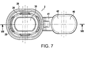
第一タブ群29の各個は、半径方向における最外面上において、これら第一タブ群29に沿って円周方向に延在するビード295を有している。第一タブ群29の配置とビード295の(半径方向の)厚さは、これら第一タブ群29がオリフィス13の中に強制的に入れ込まれるときに、平面壁15の内縁19がビード295を押し戻すと第一タブ群29がオリフィス13の中心に向かって半径方向に変形する態様で設定される。次にプレート20は、第一タブ群29によってスナップロックするので、カップ20上に固定される。図7に示すように、第一タブ群29はオリフィス13の全周に亘ってプレート20上に分布しているので、このような全周に亘って前述のスナップロックが実質的に均一に分布している。プレート20の(下面27に対向する)上面26とビード295間の距離は平面壁15の厚さに等しいので、前述のスナップロックした後で上面26はビード295によって平面壁15の内面17に支えられた状態で維持される。
Each of the
上面26は全周に亘って、第一タブ群29を取り囲む第二溝292を備えている。
The
上面26における第二溝292に第二ジョイント部92が入れ込まれ、この第二ジョイント部92の部分925が第二溝から突出しているので、部分925は、プレート20がカップ10に固定すると、内面17に接触するようになる。内面17と、この面に対接して支えられるジョイント部92との間の接触帯域は完全にオリフィス13を囲い込む。これにより、平面壁15とプレート20間の密封性が得られ、金属缶内の液体の流出を防止されることに寄与している。さらに、金属缶の内容物がガスを含有する液体である場合、このガスは平面壁15の内面17に向かってプレート20を押圧するのに寄与する。内面17によって第二ジョイント部92に印加された圧力が増大し、これはプレート20と平面壁15との間の密封性が向上するのに寄与する。
Since the second
第二ジョイント部92における部分925は、例えば2つの全周性突出物であって、これらは、図5及び図6に示すように、内面17に対向した第二ジョイント部92の(上)面上に延在する。これらの突出物は、プレート20がカップ10に固定されると、内面17に対して押し付けられ、密封を確実なものとする。
The
あるいは図12に示すように、第二ジョイント部92は横断面を実質的にV字型としたリングであっても良い。このV字における二叉の端部はそれぞれリップ(第一リップ921及び第二リップ922)を形成し、これら2つのリップは第二ジョイント部92の部分925をなし、この部分925が溝292から突出している。第二ジョイント部92は図13にも示している。
Alternatively, as shown in FIG. 12, the second
また溝292は、第二ジョイント部92のない状態で図11に示している。
Further, the
プレート20がカップ10に固定されると、リップ921及び922は、互いに離れるにつれて、内面17に対して押し付けられる。このような押し付けの最中に、第二ジョイント部92の中央部、すなわち第一リップ921と第二リップ922間の空間に存在する空気がこの空間から排出されるので、第二ジョイント部92が内面17に対する吸盤として作用する。このような吸盤効果が第二ジョイント部92を内壁17に対して一層強く付着させることに寄与しているので、プレート20と平面壁15間の密封性が強化される。
When the
上述のようにV字型の横断面を有する環状のジョイント部が平坦な表面に押し付けられると、2つのリップで吸盤として作用できるので、ジョイント部は、以下に説明するカバーを備えずとも、本発明の目的を達成するシステムとは異なる構成の開閉システムとして、密封を確実にするために利用できる。 As described above, when the annular joint portion having the V-shaped cross section is pressed against the flat surface, the two lips can act as a suction cup. As an opening / closing system having a configuration different from that of the system for achieving the object of the invention, it can be used for ensuring sealing.
好適には、本体部2、第一ジョイント部91、第二ジョイント部92で構成される構体は、本体部2を構成する硬質ポリマーと、前記ジョイント部91及び92を構成する可撓性エラストマーを同時に射出成型することにより作製できる。
Preferably, the structure composed of the main body 2, the first joint 91, and the second joint 92 is made of a hard polymer that constitutes the main body 2 and a flexible elastomer that constitutes the
この開閉具1は、図1、図2、図3、図4、図9、図10に示すように、アーム50も備える。
As shown in FIGS. 1, 2, 3, 4, 9, and 10, the opening /
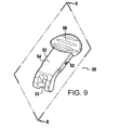
このアーム50は、一端においてグリップ56で終端し、他端において円形のロッド53を有するバー54を備えている。揚蓋40は、揚蓋40の底部42から直角に延在し、円筒壁45によって取り囲まれたクリップ43を備えている。ロッド53はクリップ43においてスナップロックし、薄肉部41によって形成されるヒンジの旋回軸に平行な軸に沿って旋回連接部を形成する。アーム50のバー54の幅(この中心軸の方向に沿った寸法)はプレート20における孔30の幅に満たないので、バー54は孔30を自在に通過できる。なおグリップ56の幅は孔30の幅よりも大きくしている。
The
アーム50は射出成型により例えばポリマーで作製されるので、単位当りの製造コストが最小限度に抑えられる。
Since the
また開閉具1は、本体部2及びアーム50とは別個のものとしてカバー80を備えている。このカバー80は、凹面85及び凸面86を有する、内側に湾曲した殻の形状である。カバー80はリム87によって界接され、また凹面85に対して実質的に直角で凹面85から延在するタブ88を備えている。カバー80は、カップ10の平面壁15の外面上に位置決めされ、オリフィス13を介してプレート20の上面26から延在する、プレート20における第二タブ28にスナップロックするタブ88を使ってプレート20上に組み立てられる。第二タブ28へのタブ88のスナップロックは、歯形を有するこれらのタブの端部の高さで実行される(図6)。したがってタブ88は、カバー80をプレート20に連結させるための手段となる。
The opening /
図7に示すように、第一タブ群29及び第二タブ群28は、プレート20上で孔30の周囲に交互に分布しており、第二タブ群28のこのような分布により、確実にカバー80とプレート20間のスナップロックが孔30の外縁全体に亘って実質的に均一に分布することになる。
As shown in FIG. 7, the
タブ群88はリム87の高さよりも低いので、タブ群88と第二タブ群28がスナップロックされると、リム87がカップ10の上面16を押し付け、カバー80と本体部20の組み合わせをロックして安定させる。したがってカップ10における平面壁15の(オリフィス13周囲における)領域がカバー80とプレート20間に挟まれる。
Since the
カバー80はU字型としている。したがってカバー80の中心部は一方側で開放したU字型の有底・非貫通の穴である。この穴は、凹面85を超えて凸面86から実質的に凹面85と直角に延在する中央スリーブ81によって画成されている。この中央スリーブ81の幅は、プレート20の孔30の幅と実質的に等しく、カバー80とプレート20が組み立てられると、中央スリーブ81は、中央スリーブ81が開放となっている側を例外として、孔30の縁部25と実質的に心合した状態で位置している。この開放側は薄肉部41が位置しているよりも上方の側である。したがって、開閉具1が再閉塞されると、アーム50は揚蓋40の部分と薄肉部41の部分よりも上方で折り返され、次いでカップ10における平面壁15の一部がアーム50と揚蓋40間に位置する。アーム50は、アーム50の上面がカバー80の凸面86と心合し、U字の頂部を例外として(図4に示すように)カバー80の中心部の空間を満たすまで、折り返すことができる。したがって、開閉具1の部分はカップ10のリム12よりも上に突出することが一切ないので、金属缶に対する容積の追加分は最低限度に抑えられる。
The
またカバー80は成型によって例えばポリマーで作製されるので、単位当りの製造コストを最低限度に抑えられる。
Further, since the
変形例として、プレート20をカップ10上にまたカバー80をプレート20上にスナップロックして組み立てることは以下に説明するように実施できる。
As a modification, assembling the
図11及び図12に示すように、プレート20の上面26における第一タブ群29(前述の説明を参照)は、繋がった状態になるよう互いの方向に拡大してスナップロック用のビード129を形成する。カバー80と共にスナップロックする作用を奏するプレート20の第二タブ群28は不要とできる。スナップロック用のビード129は、カバー80の中央スリーブ81が開放されている側を除き、実質的に孔30の全周に亘って円周状に延在している。プレート20がカップ10の平面壁15に配置されると、壁部29はオリフィス13の中に入れ込まれる。
As shown in FIGS. 11 and 12, the first tab group 29 (see the above description) on the
スナップロック用のビード129は、半径方向における最外面に、このスナップロック用のビード129全体に沿って円周状に延在する第一ビード295を備えている。スナップロック用のビード129の配置と第一ビード295の(半径方向における)厚さは、スナップロック用のビード129がオリフィス13の中に入れ込まれると平面壁15の内縁19が第一ビード295を押し戻すのでスナップロック用のビード129がオリフィス13の中心部に向かって半径方向に変形するような態様で、設定される。このため、スナップロック用のビード129を介してスナップロックすることによってプレート20はカップ10上に固定される。スナップロック用のビード129が実質的に内縁19の全周に沿って延在していることにより、プレート20をカップ10上に堅固に組み立てることが可能となる。
The snap-
スナップロック用のビード129は、上面26に対して直角に第一ビード295を超えて、第二ビード298を備える延長部の分だけ延在しており、スナップロックのビードは孔30周りにおけるこの延長部の実質的に全長に亘って延在している。この延長部は、スナップロック用のビード129の基部よりも僅かに孔30寄りに位置しているので、スナップロック用のビード129を自在にオリフィス13の中に入れ込むことができる(図13)。
The snap-
カバー80はタブ88を有し、これらのタブ88は、カバー80の凹面85に対して実質的に直角に凹面85から延在している。タブ88の端部は半径方向における内面上に溝888を有しており、カバー80がプレート20に固定されると溝888が第二ビード298とスナップロックとなるので、カバー80がプレート20に連結される(図13及び図14)。タブ88は略繋がった状態になるよう互いの方向へ拡大されているので、カバーがプレート20とさらに堅固に連結する。
次に開閉具1の機能に関して、図1、図2、図3、図4を参照して以下に説明する。
Next, the function of the opening /
開閉具1を初めて開ける前に、アーム50は上述のとおり折り畳まれている。カバー80には、初めて開ける前の状態の開閉具1を示す図3及び図4において示される舌片100が付属している。この舌片100は実質的にカバー80の凸面86の延長部内に位置しており、アーム50のバー54を覆い、グリップ56は覆っていない。舌片100は部分的又は全体的に中央スリーブ81(すなわちカバー80における中央のU字型の領域)を覆っている。舌片100はフックシステムでカバー80に連結されている。このフックシステムは、初めて開閉具1を開ける際に破壊されて、元通りに復帰できない構成としている。フックシステムは、舌片100の周縁に亘って分布する4つのリンク104を備えており、それぞれのリンクは舌100の縁部と、舌100の縁部が僅かなスペース分だけ離れている中央スリーブ81との間のブリッジを形成している。
Before opening the opening /
舌片100及び4つのリンク104は、カバー80と共に一体成型することにより、例えばポリマーで作製されるので、単位当りの生産コストを最小限度に抑えることができる。
Since the
舌片100、この舌片とカバー80を連結するリンク104、及びフックシステムはセキュリティ用蓋材を形成しており、この蓋材が破損していない状態であれば、金属缶は事前に開封されていないことが保証される。このセキュリティ用蓋材は閉塞位置におけるアーム50の阻止手段の一部を形成している。
The
また、セキュリティ用蓋材に関する他の構成も実施可能である。 Other configurations for the security lid can also be implemented.
開閉具1を初めて開いて金属缶の内容物を消費するために、アーム50がグリップ56で引き上げられ、これと同時にリンク104が破損されて舌片100が引き上げられ、以降は無効となる。
In order to open the opening /
次にアーム50を引き上げる。アーム50のバー54は、このバー54から横方向に延在する2つのピン52(図9に示す)を備えている。これらのピン52は、中央スリーブ81に沿った凸面86から(この面に対して直角に)延在する、本体80の溝82内に挿入される構造である。ピン52が溝82内に挿入されると、アーム50のグリップ56が凸面86に対して支持され、揚蓋40は開位置で停止される。したがって溝82及びピン52は、開位置におけるアーム50を停止する阻止手段を構成している。なお開位置においてアーム50を停止する他の手段も実施可能である。
Next, the
アーム50のグリップ56の幅(薄肉部41で形成されるヒンジの旋回軸方向の寸法)は中央スリーブ81の幅よりも広くしているので、アーム50が金属缶内に落下しないようにし、後で金属缶を閉めやすくしている。溝82は、ピン52が溝82内に入れ込まれるとアーム50がプレート20に対して実質的に直角となる態様で位置しているので、揚蓋40の最大開口が保証される(例えば、溝82はU字(中央スリーブ81の穴)の頂部に最も近い距離の3分の1の箇所に位置している)。このため、スリーブ81を通過する液体の流量は最適なものとなる。
Since the width of the
孔30は楕円形としており、カップ10におけるオリフィス13の形状と実質的に同一となっているが、これよりも小さめの寸法としている。このような形状のため、アーム50が開位置にあるときにアーム50の前(U字型の中央スリーブ81の頂部の領域、すなわちカップのリム12に最接近した箇所)で中央スリーブ81のうち十分な部分が離れて、利用者が消費するのに好都合な流量で金属缶内の液体が流出できるようになる。
The
開閉具1を再閉塞するために、ピン52は溝82から離され、U字の中央領域において、アーム50はカップ10の平面壁15における外面16に対接するように折り返される。次にカバー80はアーム50を離れたままにしておく。中央スリーブ81は両面(U字の両側)に2つの鋸歯状の切込み812を備えており、これらの切込み812は中央スリーブ81を僅かに超えて互いの方向へ延在している。これらの切込み812は凸面86の近傍に位置している(図2及び図3)ので、上述したように又は最初の開放前にアーム50が折り返されるとき(図3及び図4)、中央スリーブ81の幅よりも僅かに小さな幅であるバー54は切込み812を超えて(下方に)位置して切込み812とスナップロックされる。切込み812は、例えばU字の開放側(薄肉部41の上方)に極力接近して位置しているので、アーム50を切込み812から離すのに必要とされる作用は最高のものとなる。揚蓋40及びアーム50は、カバー80に連結された切込み812によって水密の閉塞位置に閉塞され、これらの切込み812はアーム50を水密の閉塞位置で保持する手段を構成している。またこれらの阻止手段は、開閉具1を最初に開く前(上記を参照)でもセキュリティ用蓋材と共に使用される。
In order to reclose the opening /
カバー80に連結された状態のアーム50を閉位置に保持する他の手段も実施可能である。
Other means of holding the
あるいは阻止手段を本体2及びアーム50にのみ位置させることもできる。
Alternatively, the blocking means can be positioned only on the main body 2 and the
プレート20に関する、また図11ないし図14に示しかつ先に説明したカバー80に関する変形の実施形態では、カバー80の中央スリーブ81が開放している側を例外として、スナップロック用のビード129は実質的に孔30の全周に亘って延在しており、アーム50が折り畳まれる(開閉具が閉位置にある)とアーム50のバー54の通過が可能となる。
In an alternative embodiment with respect to the
カバー80がプレート20に連結されると、中央スリーブ81によって形成されたU字の二叉(図14)における半径方向の外面は、スナップロック用のビード129の端部を形成する2つの面127(図12)上に静止する。これらの端面127は互いに対向して、すなわち中央スリーブ81の両側かつ外側に位置しているので、中央スリーブ81のU字の二叉を所定の位置に保持するのに寄与している。
When the
したがって、アーム50が中央スリーブ81における2つの切込み812内にスナップロックすると、中央スリーブはこのスナップロックに対する強力な耐性を示す。これは、端面127に静止している中央スリーブ81のU字型の二叉が離れるのをスナップロック用のビード129が防止しているからである。このため、本発明に係る開閉具1を閉位置にロックすれば、さらに効果的なものとなる。
Thus, when the
閉位置における開閉具1の密封は、アーム50におけるこれらの阻止手段によって保証される。また円筒壁45とプレート20の縁部25における内面と間の密着をなす密封手段並びにジョイント部91及び92によっても保証される(既述)。
The sealing of the opening /
また密封手段については他の構成も採用できる。 Also, other configurations can be adopted for the sealing means.
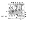
例えば、揚蓋40の周縁部47全体は、孔30を取り囲むプレート20における下面27に対接して支持される、可撓性を有する素材(例えばエラストマー)で作製された円周状の舌片で構成される。揚蓋40の残部はより剛性のあるポリマーで作製される。この構成では、第一ジョイント部91及び第一溝291は、可撓性を有する周縁部47が内面27の平坦な部分に接して支持され、揚蓋40とプレート20間のさらに良好な密封性を確実なものとする態様で、省略されている(図15)。
For example, the entire
本発明に係る開閉具1のために、水密の態様で所望の回数だけ金属缶を開閉できるので、金属缶の内容物の損失を回避し、消費していない間に物性を失うこともなく何度もこの内容物を消費することができる。
Since the metal can can be opened and closed a desired number of times in a watertight manner for the opening /
開閉具1を構成する3つの要素(本体2、アーム50、カバー80)は簡単に連続してスナップロックすることによって組み立てられる。すなわち、本体2のプレート20はカップ10のオリフィス13における内縁19に対してスナップロックする。次いで、本体2の揚蓋40がプレート20の方へ折り返されると、アーム50は、アーム50のバー54をプレート20の孔30に通すことによって揚蓋40に対してスナップロックする。アーム50がカップ10の外面16に対接するように折り返されると、カバー80はプレート20に対してスナップロックし、アーム50はカバー80によってU字型の中央に位置している。
The three elements (the main body 2, the
開閉具1は容易に、しかも最低限のコストで金属缶に作製され組み立てられ得る。
The opening /
同様に、開閉具1は、本発明に係るパッケージを構成するために、任意のパッケージの平面壁に作製され組み立てられ得る。
Similarly, the opening /
1…開閉具1 ... Opening and closing tool
2…本体部2 ... Main body
10…カップ10 ... Cup
12…リム12 ... Rim
13…オリフィス13 ... Orifice
15…平面壁15 ... plane wall
16…外面16 ... Outer surface
17…内面17 ... Inside
19…内縁19 ... Inner edge
20…プレート20 ... Plate
25…縁部25 ... Edge
26…上面26 ... top surface
27…下面27 ... Bottom surface
28…第二タブ群28 ... Second tab group
29…第一タブ群29 ... First tab group
30…孔30 ... hole
40…揚蓋40 ... Lifting lid
41…可撓性を有して成型された薄肉部41 ... Thin part molded with flexibility
42…底部42 ... Bottom
43…クリップ43 ... Clip
45…円筒壁45 ... Cylinder wall
47…周縁部47 ... Rim
50…アーム50 ... arm
52…ピン52 ... pin
53…ロッド53 ... Rod
54…バー54 ... Bar
56…グリップ56 ... Grip
80…カバー80 ... Cover
81…中央スリーブ81 ... Central sleeve
82…溝82 ... Groove
85…凹面85 ... concave surface
86…凸面86 ... Convex surface
87…リム87 ... Rim
88…タブ88 ... Tab
91…第一ジョイント部91 ... First joint part
92…第二ジョイント部92 ... Second joint part
100…舌片100 ... tongue
104…リンク104 ... Link
127…端面127 ... end face
129…スナップロック用のビード129 ... Bead for snap lock
291…第一溝291 ... 1st groove
292…第二溝292 ... Second groove
295…第一ビード295 ... 1st bead
298…第二ビード298 ... second bead
812…切込み812 ... Incision
888…溝888 ... groove
914…内壁914 ... Inner wall
915…環状の凹部915 ... annular recess
916…外壁916 ... Outer wall
921…リップ921 ... Lip
925…第二ジョイント部の部分925 ... Second joint part
Claims (15)
前記パッケージには開閉具(1)が備えられており、前記開閉具(1)は、
成型材で一体成形に構成されて前記平面壁(15)に固定された本体部(2)であって、オリフィス(13)と対向して配置された孔(30)が形成され、平面壁(15)のオリフィス(13)の縁部(19)に水密の態様で固定されたプレート(20)を有する本体部(2)と、
パッケージの内部に向かって開口する前記プレート(20)に連接され、前記孔(30)を水密の態様で閉塞できる揚蓋(40)と
を備えており、
前記開閉具(1)はさらに、前記揚蓋(40)に連結されたアーム(50)を備えており、
該アーム(50)は所定の位置で移動を阻止する阻止手段と協働することにより、該阻止手段が前記揚蓋(40)を水密の閉塞位置に維持し、アーム(50)が阻止手段から離れると揚蓋(40)が前記パッケージの内部に向かって旋回して揚蓋(40)を解放するよう構成されており、
さらにまた開閉具1は、前記本体部(2)及び前記アーム(50)とは別個のカバー(80)を備えており、
該カバー(80)は、前記揚蓋(40)を初めて開封する際に必然的に破壊されるセキュリティ用蓋材(100、104)を備えることで、該セキュリティ用蓋材(100、104)が破損していなければ、パッケージが事前に開封されていないことが保証され、前記蓋材が前記阻止手段の一部を形成し、
前記カバー(80)は前記プレート(20)と連結するための手段を備え、前記カバー(80)が前記プレートに連結されたとき前記パッケージの外部に位置しているので、前記平面壁(15)の領域が前記カバー(80)と前記プレート(20)間に挟まれてなることを特徴とするパッケージ。 A consumable package comprising a substantially flat planar wall (15) and provided with an orifice (13),
The package is provided with an opening / closing tool (1), the opening / closing tool (1),
A body part (2) configured to be integrally molded with a molding material and fixed to the planar wall (15), and formed with a hole (30) disposed opposite to the orifice (13) to form a planar wall ( A body (2) having a plate (20) secured in a watertight manner to the edge (19) of the orifice (13) of 15);
It is connected to the plate (20) that opens toward the inside of the package, and includes a lifting lid (40) that can close the hole (30) in a watertight manner.
The opening / closing tool (1) further includes an arm (50) connected to the lifting lid (40),
By the arm (50) which cooperates with the blocking means for preventing movement at a predetermined position, said blocking means to maintain the Agefuta (40) in watertight closed position, the blocking means arm (50) When lifted , the lifting lid (40) is configured to pivot toward the inside of the package to release the lifting lid (40),
Furthermore, the opening / closing tool 1 includes a cover (80) separate from the main body (2) and the arm (50),
The cover (80) includes a security lid (100, 104) that is inevitably destroyed when the lifting lid (40) is opened for the first time, so that the security lid (100, 104) If not damaged, it is guaranteed that the package has not been previously opened, the lid material forms part of the blocking means,
The cover (80) comprises means for connecting to the plate (20), and is located outside the package when the cover (80) is connected to the plate, so that the planar wall (15) The package is characterized by being sandwiched between the cover (80) and the plate (20).
Applications Claiming Priority (7)
| Application Number | Priority Date | Filing Date | Title |
|---|---|---|---|
| FR0805175A FR2936227B3 (en) | 2008-09-22 | 2008-09-22 | INTEGRATED OPENING AND REFERRING DEVICE FOR ALL TYPES OF GASEOUS OR NON-DRINKING CANISTERS |
| FR08/05175 | 2008-09-22 | ||
| FR09/00799 | 2009-02-23 | ||
| FR0900799A FR2936228A1 (en) | 2008-09-22 | 2009-02-23 | INTEGRATED OPENING AND REFERRING DEVICE FOR ALL TYPES OF GASEOUS OR NON-DRINKING CANISTERS |
| FR0953920A FR2946626A1 (en) | 2009-06-12 | 2009-06-12 | Package i.e. beverage can, for packaging liquid beverage, has arm engaged with immobilization unit in position so as to maintain door in sealed-shut position, and cover provided with safety relief device partly forming immobilization unit |
| FR0953920 | 2009-06-12 | ||
| PCT/FR2009/051763 WO2010031975A1 (en) | 2008-09-22 | 2009-09-18 | Package provided with a leaktight opening and closing device |
Publications (3)
| Publication Number | Publication Date |
|---|---|
| JP2012502856A JP2012502856A (en) | 2012-02-02 |
| JP2012502856A5 JP2012502856A5 (en) | 2014-01-09 |
| JP5448233B2 true JP5448233B2 (en) | 2014-03-19 |
Family
ID=41510996
Family Applications (1)
| Application Number | Title | Priority Date | Filing Date |
|---|---|---|---|
| JP2011527384A Expired - Fee Related JP5448233B2 (en) | 2008-09-22 | 2009-09-18 | Package with liquid leakage prevention switch |
Country Status (9)
| Country | Link |
|---|---|
| US (1) | US8783493B2 (en) |
| EP (1) | EP2326560B1 (en) |
| JP (1) | JP5448233B2 (en) |
| KR (1) | KR101337013B1 (en) |
| CN (1) | CN102216165B (en) |
| BR (1) | BRPI0919011A2 (en) |
| CA (1) | CA2738097A1 (en) |
| ES (1) | ES2483997T3 (en) |
| WO (1) | WO2010031975A1 (en) |
Families Citing this family (17)
| Publication number | Priority date | Publication date | Assignee | Title |
|---|---|---|---|---|
| US8857644B2 (en) | 2008-11-26 | 2014-10-14 | B.E. Inventive, Llc | Container |
| US9463910B2 (en) | 2010-04-06 | 2016-10-11 | c2c Beteiligungs—GmbH | Container closure device and container having such a closure device |
| FR2970239B1 (en) | 2011-01-10 | 2013-02-08 | 3L Distrib | PACKAGE EQUIPPED WITH A SEALED OPENING AND CLOSING DEVICE |
| KR200469736Y1 (en) * | 2012-08-21 | 2013-11-06 | 허홍 | Bottle cap capable open and shut using the lever |
| US9113698B2 (en) | 2013-03-15 | 2015-08-25 | Camelbak Products, Llc | Drink containers and cap assemblies |
| WO2015095326A1 (en) * | 2013-12-18 | 2015-06-25 | Ignite Usa, Llc | Sealing mechanism for beverage container |
| USD732337S1 (en) | 2013-12-18 | 2015-06-23 | Ignite Usa, Llc | Lid for beverage container |
| USD774827S1 (en) | 2015-01-16 | 2016-12-27 | Ignite Usa, Llc | Beverage container |
| USD773250S1 (en) | 2015-01-16 | 2016-12-06 | Ignite Usa, Llc | Beverage container |
| USD774828S1 (en) | 2015-01-16 | 2016-12-27 | Ignite Usa, Llc | Beverage container |
| DE102015000914B3 (en) * | 2015-01-26 | 2015-09-24 | Euro-Cap Gmbh | Can closure, especially for a milk can |
| DE102015110773A1 (en) | 2015-06-05 | 2016-12-08 | Can2Close Gmbh | Container closure device and container |
| AU2017226178A1 (en) | 2016-03-04 | 2018-09-20 | Cool Gear International, Llc | Resealable container |
| US10336513B2 (en) | 2017-02-24 | 2019-07-02 | Ignite Usa, Llc | Lid having a pre-venting lid lever and a seal arm assembly |
| EP3584191A1 (en) * | 2018-06-19 | 2019-12-25 | Top Cap Holding GmbH | Metallic can lid |
| WO2020047730A1 (en) * | 2018-09-04 | 2020-03-12 | 石榴进化有限公司 | Leak-proof container cover and storage device |
| DE102021106977B4 (en) * | 2021-03-22 | 2024-03-07 | Ardagh Metal Packaging Europe Gmbh | Closure arrangement for a beverage container and method for repeatably closing a beverage container with a closure arrangement |
Family Cites Families (11)
| Publication number | Priority date | Publication date | Assignee | Title |
|---|---|---|---|---|
| FR2170298A6 (en) * | 1971-11-22 | 1973-09-14 | Lutzker Robert | |
| JPH0460866U (en) * | 1990-10-04 | 1992-05-25 | ||
| JPH0614056U (en) * | 1992-07-30 | 1994-02-22 | 広浜金属工業株式会社 | Cap unit |
| CN2403697Y (en) * | 2000-01-17 | 2000-11-01 | 常州市赫利来塑料有限公司 | Full-sealing antifake plastic package bucket |
| US20040159665A1 (en) * | 2003-02-13 | 2004-08-19 | Gloria Morrissey | Easy opening venting and resealable container closure |
| DE60328856D1 (en) * | 2003-05-22 | 2009-10-01 | Agilent Technologies Inc | Septum with flap |
| EP1767464A1 (en) * | 2005-09-23 | 2007-03-28 | Crown Packaging Technology, Inc | Sealing device for a container |
| US20070164026A1 (en) * | 2006-01-04 | 2007-07-19 | Morrissey Brian J | Automatic opening, venting, and closing re-sealable container closure |
| JO2803B1 (en) * | 2006-05-10 | 2014-03-15 | كراون باكيجنج تكنولوجي،انك. | Opening Device |
| US8240498B2 (en) * | 2006-10-31 | 2012-08-14 | Crown Packaging Technology, Inc. | Resealable closure |
| EP2755529B1 (en) * | 2011-09-13 | 2018-11-14 | Ignite USA, LLC | Seal mechanism for beverage container |
-
2009
- 2009-09-18 EP EP09748412.5A patent/EP2326560B1/en not_active Not-in-force
- 2009-09-18 CA CA2738097A patent/CA2738097A1/en not_active Abandoned
- 2009-09-18 JP JP2011527384A patent/JP5448233B2/en not_active Expired - Fee Related
- 2009-09-18 CN CN200980143386.9A patent/CN102216165B/en not_active Expired - Fee Related
- 2009-09-18 ES ES09748412.5T patent/ES2483997T3/en active Active
- 2009-09-18 US US13/120,405 patent/US8783493B2/en not_active Expired - Fee Related
- 2009-09-18 WO PCT/FR2009/051763 patent/WO2010031975A1/en active Application Filing
- 2009-09-18 BR BRPI0919011A patent/BRPI0919011A2/en active Search and Examination
- 2009-09-18 KR KR1020117008821A patent/KR101337013B1/en not_active IP Right Cessation
Also Published As
| Publication number | Publication date |
|---|---|
| US8783493B2 (en) | 2014-07-22 |
| CA2738097A1 (en) | 2010-03-25 |
| US20120103987A1 (en) | 2012-05-03 |
| KR101337013B1 (en) | 2013-12-05 |
| EP2326560A1 (en) | 2011-06-01 |
| CN102216165A (en) | 2011-10-12 |
| KR20110059648A (en) | 2011-06-02 |
| CN102216165B (en) | 2014-05-07 |
| WO2010031975A1 (en) | 2010-03-25 |
| BRPI0919011A2 (en) | 2016-08-09 |
| JP2012502856A (en) | 2012-02-02 |
| ES2483997T3 (en) | 2014-08-08 |
| EP2326560B1 (en) | 2014-05-14 |
Similar Documents
| Publication | Publication Date | Title |
|---|---|---|
| JP5448233B2 (en) | Package with liquid leakage prevention switch | |
| JP2012502856A5 (en) | ||
| AU2006276269B2 (en) | Dispensing closure, package and method of manufacture | |
| EP1842789B1 (en) | System including a closure and a container attachment | |
| US7717307B2 (en) | Closure assembly having a spout with a memory band for spout directing | |
| TWI439396B (en) | Can end lid for a can, drink can comprising said lid, and manufacturing process for a can | |
| US20130320012A1 (en) | Packaging provided with a sealed opening and closing device | |
| CZ2003922A3 (en) | Closure lid and resealable closure system | |
| JPH09183455A (en) | Lid made of plastic | |
| US20140305942A1 (en) | Closing Element and Container Provided with Such a Closing Element | |
| US6776301B2 (en) | Cap with one-way de-gas feature | |
| JP2009508778A (en) | Cap for neck of container, container with plug, and method of assembling the plug | |
| US20070284398A1 (en) | Container closure assembly with extendable spout and tamper-evident portion | |
| JP6086743B2 (en) | Refill container | |
| JP5997978B2 (en) | Cup container with lid | |
| JP4627063B2 (en) | Container cap structure | |
| JP7157996B2 (en) | cap | |
| JP5380330B2 (en) | container | |
| JP2008285187A (en) | Lid with spouting cylinder |
Legal Events
| Date | Code | Title | Description |
|---|---|---|---|
| A621 | Written request for application examination |
Free format text: JAPANESE INTERMEDIATE CODE: A621 Effective date: 20120814 |
|
| A977 | Report on retrieval |
Free format text: JAPANESE INTERMEDIATE CODE: A971007 Effective date: 20130729 |
|
| A131 | Notification of reasons for refusal |
Free format text: JAPANESE INTERMEDIATE CODE: A131 Effective date: 20130806 |
|
| A601 | Written request for extension of time |
Free format text: JAPANESE INTERMEDIATE CODE: A601 Effective date: 20131105 |
|
| A521 | Request for written amendment filed |
Free format text: JAPANESE INTERMEDIATE CODE: A821 Effective date: 20131106 |
|
| A524 | Written submission of copy of amendment under article 19 pct |
Free format text: JAPANESE INTERMEDIATE CODE: A524 Effective date: 20131106 |
|
| A602 | Written permission of extension of time |
Free format text: JAPANESE INTERMEDIATE CODE: A602 Effective date: 20131112 |
|
| TRDD | Decision of grant or rejection written | ||
| A01 | Written decision to grant a patent or to grant a registration (utility model) |
Free format text: JAPANESE INTERMEDIATE CODE: A01 Effective date: 20131203 |
|
| A61 | First payment of annual fees (during grant procedure) |
Free format text: JAPANESE INTERMEDIATE CODE: A61 Effective date: 20131221 |
|
| R150 | Certificate of patent or registration of utility model |
Free format text: JAPANESE INTERMEDIATE CODE: R150 |
|
| LAPS | Cancellation because of no payment of annual fees |