JP5445216B2 - Planetary gear mechanism - Google Patents
Planetary gear mechanism Download PDFInfo
- Publication number
- JP5445216B2 JP5445216B2 JP2010038737A JP2010038737A JP5445216B2 JP 5445216 B2 JP5445216 B2 JP 5445216B2 JP 2010038737 A JP2010038737 A JP 2010038737A JP 2010038737 A JP2010038737 A JP 2010038737A JP 5445216 B2 JP5445216 B2 JP 5445216B2
- Authority
- JP
- Japan
- Prior art keywords
- gear
- shaft
- input
- internal gear
- output
- Prior art date
- Legal status (The legal status is an assumption and is not a legal conclusion. Google has not performed a legal analysis and makes no representation as to the accuracy of the status listed.)
- Expired - Fee Related
Links
- 230000007246 mechanism Effects 0.000 title claims description 115
- 230000009467 reduction Effects 0.000 claims description 73
- 230000002093 peripheral effect Effects 0.000 claims description 27
- 238000005520 cutting process Methods 0.000 description 11
- 230000000694 effects Effects 0.000 description 10
- 238000004519 manufacturing process Methods 0.000 description 9
- 239000003638 chemical reducing agent Substances 0.000 description 7
- 238000003780 insertion Methods 0.000 description 6
- 230000037431 insertion Effects 0.000 description 6
- 230000013011 mating Effects 0.000 description 6
- 238000003754 machining Methods 0.000 description 4
- 239000000284 extract Substances 0.000 description 3
- 230000004048 modification Effects 0.000 description 3
- 238000012986 modification Methods 0.000 description 3
- 230000008859 change Effects 0.000 description 2
- 238000010586 diagram Methods 0.000 description 2
- 230000004323 axial length Effects 0.000 description 1
- 238000009434 installation Methods 0.000 description 1
- 238000000034 method Methods 0.000 description 1
- 230000000149 penetrating effect Effects 0.000 description 1
- 230000008569 process Effects 0.000 description 1
- 238000005549 size reduction Methods 0.000 description 1
Images


Classifications
-
- F—MECHANICAL ENGINEERING; LIGHTING; HEATING; WEAPONS; BLASTING
- F16—ENGINEERING ELEMENTS AND UNITS; GENERAL MEASURES FOR PRODUCING AND MAINTAINING EFFECTIVE FUNCTIONING OF MACHINES OR INSTALLATIONS; THERMAL INSULATION IN GENERAL
- F16H—GEARING
- F16H1/00—Toothed gearings for conveying rotary motion
- F16H1/28—Toothed gearings for conveying rotary motion with gears having orbital motion
- F16H1/32—Toothed gearings for conveying rotary motion with gears having orbital motion in which the central axis of the gearing lies inside the periphery of an orbital gear
Landscapes
- Engineering & Computer Science (AREA)
- General Engineering & Computer Science (AREA)
- Mechanical Engineering (AREA)
- Retarders (AREA)
Description
本発明は、遊星歯車機構に関する。 The present invention relates to a planetary gear mechanism.
モータの回転等を減速するために、遊星歯車機構をもつ減速機が用いられている。この遊星歯車機構としては、第1軸と、第1軸に設けた偏心体を介してこの第1軸に対して偏心回転可能な状態で取付けられた外歯歯車と、外歯歯車が内接噛合する内歯歯車と、外歯歯車に外歯歯車の自転成分のみを伝達する手段を介して連結された第2軸と、を備えた遊星歯車機構が広く知られている。そして、この遊星歯車機構の具体的な例として、サイクロイド差動遊星歯車機構が知られている。 A reduction gear having a planetary gear mechanism is used to reduce the rotation of the motor and the like. The planetary gear mechanism includes a first shaft, an external gear attached in an eccentrically rotatable manner to the first shaft via an eccentric body provided on the first shaft, and an external gear. A planetary gear mechanism including an internal gear that meshes and a second shaft that is connected to the external gear via a means that transmits only the rotation component of the external gear is widely known. A cycloid differential planetary gear mechanism is known as a specific example of this planetary gear mechanism.
サイクロイド差動遊星歯車機構を用いた減速機は、一般的な歯車のインボリュート歯形の遊星減速機構に比べて、一段で高い減速比がとれるうえ、噛み合い率が高く高効率が得られる反面、偏心揺動回転から出力を取り出すため機構が複雑となり、高コストとなる傾向があった。 The speed reducer using the cycloid differential planetary gear mechanism can achieve a high reduction ratio in one stage and a high meshing rate and high efficiency compared to a general gear involute planetary speed reduction mechanism, but it is eccentric. Since the output is extracted from the dynamic rotation, the mechanism tends to be complicated and expensive.
一般的なサイクロイド差動遊星歯車機構は、ピン歯車を内歯車としてエピトロコイド外歯歯車を内接偏心揺動させ、内ピンを介して出力を得ている。そして、偏心によるアンバランスを打ち消すために、偏心の位相と逆の位相に同じ構造の外歯歯車を追加したり、偏心方向を120°ずらした状態の位相の同じ構造の2枚の外歯歯車を追加している(特許文献1参照)。 In a general cycloid differential planetary gear mechanism, an epitrochoid external gear is inscribed eccentrically and an output is obtained via an internal pin with a pin gear as an internal gear. In order to cancel the unbalance due to eccentricity, an external gear having the same structure is added to the phase opposite to the eccentric phase, or two external gears having the same phase with the eccentric direction shifted by 120 °. Is added (see Patent Document 1).
しかしながら、従来のサイクロイド差動遊星歯車機構は、高い変速比(減速比)が得られないという問題があった。このため、従来の機構を有する減速機でより高い減速比(例えば100以上)を実現するためには、入力軸の前又は出力軸の後にもう1段の減速機構又は減速ユニットを追加しなければならず、大幅なコストアップや設置スペースの増大を招いてしまった。 However, the conventional cycloid differential planetary gear mechanism has a problem that a high gear ratio (reduction ratio) cannot be obtained. For this reason, in order to achieve a higher reduction ratio (for example, 100 or more) with a reduction gear having a conventional mechanism, an additional reduction mechanism or reduction unit must be added before the input shaft or after the output shaft. This has led to a significant increase in cost and installation space.
具体的には、エピトロコイド歯車を構成するためには、内歯車を多数のピンで構成する必要がある。そして、内周に配置可能なピンの本数は、特に小型の減速機の場合、多くなる必要がある。しかし、ピンの本数を増やすためには、ピンの径を細くする必要がある。このような選択は現実的には無理があり、結果として高減速比の構造を実現出来なくなっていた。 Specifically, in order to configure an epitrochoid gear, it is necessary to configure the internal gear with a large number of pins. The number of pins that can be arranged on the inner periphery needs to be increased particularly in the case of a small reduction gear. However, in order to increase the number of pins, it is necessary to reduce the diameter of the pins. Such a selection is practically impossible, and as a result, a structure with a high reduction ratio cannot be realized.
本発明は上記実状に鑑みてなされたものであり、高い変速比を達成でき、かつ小型化が達成できる遊星歯車機構を提供することを本発明の課題とする。 This invention is made | formed in view of the said actual condition, and makes it the subject of this invention to provide the planetary gear mechanism which can achieve a high gear ratio and can achieve size reduction.
上記課題を解決するために本発明者等は、遊星歯車機構について検討を重ねた結果、本発明をなすに到った。 In order to solve the above-mentioned problems, the present inventors have studied the planetary gear mechanism, and as a result, have come to make the present invention.
すなわち、請求項1に係る本発明の遊星歯車機構は、内周面に第1内歯歯車が形成された第1部材と、内周面に第2内歯歯車が形成されるとともに、入出力軸線を中心に第1部材に対して相対回転可能な第2部材と、環状に形成され、外周面に第1内歯歯車と噛合可能な第1外歯歯車および第2内歯歯車と噛合可能な第2外歯歯車を備え、第1外歯歯車の歯数は第1内歯歯車の歯数よりも少なく、第2外歯歯車の歯数は第2内歯歯車の歯数よりも少なく形成されており、第1部材および第2部材に対して揺動することにより、第1外歯歯車の円周上の一部のみが第1内歯歯車と噛合し、第2外歯歯車の円周上の一部のみが第2内歯歯車と噛合するように形成された揺動部材と、入出力軸線に対して偏心した外周面を有する偏心部を備えるとともに、偏心部が揺動部材の内周面を支持し入出力軸線を中心に回転することによって揺動部材を揺動させる、または、揺動部材が揺動することにより入出力軸線を中心に回転させられる第3部材と、を備え、第3部材に駆動力を入力して揺動部材を揺動させるとともに回転させ、第1外歯歯車と第1内歯歯車とが噛合する円周上の位置および第2外歯歯車と第2内歯歯車とが噛合する円周上の位置を移動させることにより、第1部材および第2部材のうちの少なくとも一方に減速された駆動力を出力させる、または、第1部材および第2部材のうちの少なくとも一方に駆動力を入力して、第1外歯歯車と第1内歯歯車とが噛合する円周上の位置および第2外歯歯車と第2内歯歯車とが噛合する円周上の位置を移動させ、揺動部材を揺動させるとともに回転させることにより、第3部材に増速された駆動力を出力させ、第2部材は、その一部が第3部材の軸心部に内挿され、第3部材と、第2部材の第3部材に内挿された部分の間には、第2部材支持軸受けが配されていることを特徴とする。 That is, the planetary gear mechanism according to the first aspect of the present invention includes a first member having a first internal gear formed on the inner peripheral surface, a second internal gear formed on the inner peripheral surface, and an input / output A second member that can rotate relative to the first member around the axis, and an annular outer surface that can mesh with the first external gear and the second internal gear that can mesh with the first internal gear. A second external gear, the number of teeth of the first external gear is less than the number of teeth of the first internal gear, and the number of teeth of the second external gear is less than the number of teeth of the second internal gear. Formed and swings relative to the first member and the second member, so that only a part of the circumference of the first external gear meshes with the first internal gear, and the second external gear A swinging member formed so that only a part of the circumference meshes with the second internal gear, and an eccentric portion having an outer peripheral surface eccentric with respect to the input / output axis. Further, the eccentric portion supports the inner peripheral surface of the swing member and rotates about the input / output axis, thereby swinging the swing member, or the swing member swings about the input / output axis. A third member that is rotated, and a driving force is input to the third member to cause the swinging member to swing and rotate so that the first external gear and the first internal gear mesh with each other. And the position on the circumference where the second external gear and the second internal gear mesh with each other, the reduced driving force is output to at least one of the first member and the second member. Alternatively, the driving force is input to at least one of the first member and the second member, and the position on the circumference where the first external gear and the first internal gear mesh with each other and the second external gear, The position on the circumference where the second internal gear meshes is moved, and the swing member is swung. By rotating together, the third member is caused to output the increased driving force, and a part of the second member is inserted into the axial center of the third member, and the third member and the second member Between the part inserted in the 3rd member, the 2nd member support bearing is distribute | arranged, It is characterized by the above-mentioned.
請求項2に係る本発明の遊星歯車機構は、請求項1において、第1外歯歯車と第1内歯歯車の一方は、入出力軸線方向に伸びる第1ピンよりなることを特徴とする。 A planetary gear mechanism according to a second aspect of the present invention is characterized in that, in the first aspect, one of the first external gear and the first internal gear includes a first pin extending in the input / output axis direction.
請求項3に係る本発明の遊星歯車機構は、請求項1〜2の何れか1項において、第2外歯歯車と第2内歯歯車の一方は、入出力軸線方向に伸びる第2ピンよりなることを特徴とする。 The planetary gear mechanism according to a third aspect of the present invention is the planetary gear mechanism according to the first or second aspect, wherein one of the second external gear and the second internal gear is from a second pin extending in the input / output axis direction. It is characterized by becoming.
請求項4に係る本発明の遊星歯車機構は、請求項2〜3の何れか1項において、各外歯歯車と各内歯歯車の他方は、トロコイド歯形で形成されていることを特徴とする。 A planetary gear mechanism according to a fourth aspect of the present invention is the planetary gear mechanism according to any one of the second to third aspects, wherein the other of the external gears and the internal gears is formed with a trochoidal tooth profile. .
請求項5に係る本発明の遊星歯車機構は、請求項1〜4の何れか1項において、第1外歯歯車の中心軸と第2外歯歯車の中心軸は、同軸に設けられていることを特徴とする。
The planetary gear mechanism of the present invention according to
請求項6に係る本発明の遊星歯車機構は、請求項2において、第1ピンは、ピン本体と、ピン本体に回転可能な状態で外装されたカラーと、を有することを特徴とする。 The planetary gear mechanism according to a sixth aspect of the present invention is characterized in that, in the second aspect, the first pin has a pin main body and a collar that is rotatably mounted on the pin main body.
請求項7に係る本発明の遊星歯車機構は、請求項3において、第2ピンは、ピン本体と、ピン本体に回転可能な状態で外装されたカラーと、を有することを特徴とする。 The planetary gear mechanism according to a seventh aspect of the present invention is the planetary gear mechanism according to the third aspect, wherein the second pin has a pin main body and a collar that is rotatably mounted on the pin main body.
請求項8に係る本発明の遊星歯車機構は、請求項1〜7の何れか1項において、偏心部と揺動部材との間には揺動部材支持軸受けが配されていることを特徴とする。 The planetary gear mechanism according to an eighth aspect of the present invention is the planetary gear mechanism according to any one of the first to seventh aspects, wherein a swinging member support bearing is disposed between the eccentric portion and the swinging member. To do.
請求項9に係る本発明の遊星歯車機構は、請求項1〜8において、第2部材支持軸受けは、第3部材の偏心部と、第2部材の第3部材に内挿された部分の間に配されていることを特徴とする。 The planetary gear mechanism of the present invention according to claim 9 is the planetary gear mechanism according to claim 1, wherein the second member support bearing is between the eccentric portion of the third member and the portion inserted into the third member of the second member. It is arranged in.
請求項10に係る本発明の遊星歯車機構は、請求項1〜9の何れか1項において、第3部材を入力軸とし、第2部材を出力軸とする減速機構であることを特徴とする。 A planetary gear mechanism according to a tenth aspect of the present invention is the speed reduction mechanism according to any one of the first to ninth aspects, wherein the third member is an input shaft and the second member is an output shaft. .
請求項11に係る本発明の遊星歯車機構は、請求項2および3において、第1部材は、第2部材および第3部材を回転可能に支持するハウジングであって、第2部材は、第3部材に入力された駆動力を減速して出力する出力軸であり、第1内歯歯車は第1部材から突出した第1ピンにより形成され、第2外歯歯車は揺動部材から突出した第2ピンにより形成されたことを特徴とする。 According to an eleventh aspect of the planetary gear mechanism of the present invention, in the second and third aspects, the first member is a housing that rotatably supports the second member and the third member, and the second member is the third member. An output shaft that decelerates and outputs a driving force input to the member, the first internal gear is formed by a first pin protruding from the first member, and the second external gear is a first pin protruding from the swing member. It is formed by two pins.
請求項12に係る本発明の遊星歯車機構は、請求項2および3において、第1部材は、第2部材および第3部材を回転可能に支持するハウジングであって、第2部材は、第3部材に入力された駆動力を減速して出力する出力軸であり、第1外歯歯車は揺動部材から突出した第1ピンにより形成され、第2内歯歯車は第2部材から突出した第2ピンにより形成されたことを特徴とする。 A planetary gear mechanism according to a twelfth aspect of the present invention is the planetary gear mechanism according to the twelfth aspect of the present invention, wherein the first member is a housing that rotatably supports the second member and the third member, and the second member is the third member. An output shaft that decelerates and outputs the driving force input to the member, the first external gear is formed by a first pin protruding from the swing member, and the second internal gear is a first pin protruding from the second member. It is formed by two pins.
請求項13に係る本発明の遊星歯車機構は、請求項1〜12の何れか1項において、第3部材は、偏心部のアンバランス回転を打ち消すカウンターバランサを有することを特徴とする。 A planetary gear mechanism according to a thirteenth aspect of the present invention is characterized in that, in any one of the first to twelfth aspects, the third member has a counter balancer that cancels unbalanced rotation of the eccentric portion.
請求項14に係る本発明の遊星歯車機構は、請求項13において、カウンターバランサは、第3部材を部分的に刳り抜いた軽量孔であることを特徴とする。 A planetary gear mechanism according to a fourteenth aspect of the present invention is the planetary gear mechanism according to the thirteenth aspect, characterized in that the counter balancer is a lightweight hole partially hollowed out from the third member.
請求項15に係る本発明の遊星歯車機構は、請求項1〜14の何れか1項において、第2部材は出力軸支持軸受けを介して、第1部材により回転可能に支持されており、出力軸支持軸受けの内輪を第2部材と一体に形成したことを特徴とする。 The planetary gear mechanism of the present invention according to claim 15, in any one of claims 1 to 14, the second member through the output shaft support bearing, is rotatably supported by the first member, the output The inner ring of the shaft support bearing is formed integrally with the second member.
請求項16に係る本発明の遊星歯車機構は、請求項1〜15の何れか一項において、第3部材は、電動モータにより駆動され、電動モータのケースは、第1部材または第2部材と一体的に形成され、電動モータの出力軸と第3部材とが一体的に形成されたことを特徴とする。 A planetary gear mechanism according to a sixteenth aspect of the present invention is the planetary gear mechanism according to any one of the first to fifteenth aspects, wherein the third member is driven by an electric motor, and the case of the electric motor includes the first member or the second member. It is formed integrally, and the output shaft of the electric motor and the third member are formed integrally.
請求項17に係る本発明の遊星歯車機構は、共通の入出力軸線を中心として、入力軸および出力軸を回転可能に支持する固定されたハウジングと、入力軸および出力軸のうちの一方であって、入出力軸線に対して偏心した偏心軸を中心とする偏心部を有する第1軸と、入力軸および出力軸のうちの他方であって、第2内歯歯車が設けられた第2軸と、偏心部に支持される筒状部と、ハウジングに形成された入出力軸線を中心とする第1内歯歯車に係合する第1外歯歯車と、第2内歯歯車と係合する第2外歯歯車と、が形成され、第1外歯歯車の歯数は第1内歯歯車の歯数よりも少なく、第2外歯歯車の歯数は第2内歯歯車の歯数よりも少なく形成されており、偏心軸に対して回転するとともに、ハウジングおよび第2軸に対して揺動することにより、第1外歯歯車の円周上の一部のみが第1内歯歯車と噛合し、第2外歯歯車の円周上の一部のみが第2内歯歯車と噛合するように形成された揺動部材と、を備えた遊星歯車機構において、第1内歯歯車は、ハウジングから突出し入出力軸線方向に伸びる第1ピンよりなり、第2外歯歯車は、揺動部材から突出し入出力軸線方向に伸びる第2ピンよりなり、第1軸に駆動力を入力して揺動部材を揺動させるとともに回転させ、第1外歯歯車と第1内歯歯車とが噛合する円周上の位置および第2外歯歯車と第2内歯歯車とが噛合する円周上の位置を移動させることにより、第2軸に減速された駆動力を出力させる、または、第2軸に駆動力を入力して、第1外歯歯車と第1内歯歯車とが噛合する円周上の位置および第2外歯歯車と第2内歯歯車とが噛合する円周上の位置を移動させ、揺動部材を揺動させるとともに回転させることにより、第1軸に増速された駆動力を出力させ、第2軸は、その一部が第1軸の軸心部に内挿され、第1軸と、第2軸の第1軸に内挿された部分の間には、第2部材支持軸受けが配されていることを特徴とする。 The planetary gear mechanism according to the seventeenth aspect of the present invention is one of a fixed housing that rotatably supports an input shaft and an output shaft around a common input / output axis, and one of the input shaft and the output shaft. A first shaft having an eccentric portion centered on an eccentric shaft that is eccentric with respect to the input / output axis, and a second shaft that is the other of the input shaft and the output shaft and is provided with a second internal gear. A cylindrical portion supported by the eccentric portion, a first external gear engaged with a first internal gear centered on an input / output axis formed in the housing, and a second internal gear A second external gear, wherein the number of teeth of the first external gear is less than the number of teeth of the first internal gear, and the number of teeth of the second external gear is greater than the number of teeth of the second internal gear. Is formed so that it rotates with respect to the eccentric shaft and swings with respect to the housing and the second shaft. Accordingly, only a part of the circumference of the first external gear meshes with the first internal gear, and only a part of the circumference of the second external gear meshes with the second internal gear. The first internal gear includes a first pin that protrudes from the housing and extends in the input / output axis direction, and the second external gear protrudes from the swing member. It consists of a second pin extending in the direction of the output axis, and a driving force is input to the first shaft to swing and rotate the swinging member so that the first external gear and the first internal gear mesh with each other. , And a position on the circumference where the second external gear and the second internal gear mesh with each other, the decelerated driving force is output to the second shaft, or the driving force is applied to the second shaft. , The position on the circumference where the first external gear and the first internal gear mesh, and the second external gear and the second internal gear By moving a position on the circumference where the vehicle meshes, and swinging and rotating the swinging member, the driving force increased in speed is output to the first shaft. A second member support bearing is disposed between the first shaft and the portion of the second shaft that is inserted into the shaft center portion of the first shaft. .
請求項18に係る本発明の遊星歯車機構は、共通の入出力軸線を中心として、入力軸および出力軸を回転可能に支持する固定されたハウジングと、入力軸および出力軸のうちの一方であって、入出力軸線に対して偏心した偏心軸を中心とする偏心部を有する第1軸と、入力軸および出力軸のうちの他方であって、第2内歯歯車が設けられた第2軸と、偏心部に支持される筒状部と、ハウジングに形成された入出力軸線を中心とする第1内歯歯車に係合する第1外歯歯車と、第2内歯歯車と係合する第2外歯歯車と、が形成され、第1外歯歯車の歯数は第1内歯歯車の歯数よりも少なく、第2外歯歯車の歯数は第2内歯歯車の歯数よりも少なく形成されており、偏心軸に対して回転するとともに、ハウジングおよび第2軸に対して揺動することにより、第1外歯歯車の円周上の一部のみが第1内歯歯車と噛合し、第2外歯歯車の円周上の一部のみが第2内歯歯車と噛合するように形成された揺動部材と、を備えた遊星歯車機構において、第1外歯歯車は、揺動部材から突出し入出力軸線方向に伸びる第1ピンよりなり、第2内歯歯車は、第2軸から突出し入出力軸線方向に伸びる第2ピンよりなり、第1軸に駆動力を入力して揺動部材を揺動させるとともに回転させ、第1外歯歯車と第1内歯歯車とが噛合する円周上の位置および第2外歯歯車と第2内歯歯車とが噛合する円周上の位置を移動させることにより、第2軸に減速された駆動力を出力させる、または、第2軸に駆動力を入力して、第1外歯歯車と第1内歯歯車とが噛合する円周上の位置および第2外歯歯車と第2内歯歯車とが噛合する円周上の位置を移動させ、揺動部材を揺動させるとともに回転させることにより、第1軸に増速された駆動力を出力させ、第2軸は、その一部が第1軸の軸心部に内挿され、第1軸と、第2軸の第1軸に内挿された部分の間には、第2部材支持軸受けが配されていることを特徴とする。 The planetary gear mechanism according to the eighteenth aspect of the present invention is one of a fixed housing that rotatably supports an input shaft and an output shaft about a common input / output axis, and one of the input shaft and the output shaft. A first shaft having an eccentric portion centered on an eccentric shaft that is eccentric with respect to the input / output axis, and a second shaft that is the other of the input shaft and the output shaft and is provided with a second internal gear. A cylindrical portion supported by the eccentric portion, a first external gear engaged with a first internal gear centered on an input / output axis formed in the housing, and a second internal gear A second external gear, wherein the number of teeth of the first external gear is less than the number of teeth of the first internal gear, and the number of teeth of the second external gear is greater than the number of teeth of the second internal gear. Is formed so that it rotates with respect to the eccentric shaft and swings with respect to the housing and the second shaft. Accordingly, only a part of the circumference of the first external gear meshes with the first internal gear, and only a part of the circumference of the second external gear meshes with the second internal gear. In the planetary gear mechanism provided with the oscillating member, the first external gear includes a first pin that protrudes from the oscillating member and extends in the input / output axis direction, and the second internal gear includes the second shaft from the second shaft. A second pin that protrudes and extends in the direction of the input / output axis, inputs a driving force to the first shaft, swings and rotates the swing member, and engages the first external gear and the first internal gear. By moving the position on the circumference and the position on the circumference where the second external gear and the second internal gear mesh with each other, the reduced driving force is output to the second axis, or the second axis is The position on the circumference where the driving force is input and the first external gear and the first internal gear mesh with each other, and the second external gear and the second internal gear. Is moved, the rocking member is swung and rotated to output the driving force increased in speed to the first shaft, and the second shaft has a part of the first shaft. A second member support bearing is disposed between a portion of the first shaft and the first shaft of the second shaft that is inserted in the shaft center portion of the shaft.
請求項1に係る本発明の遊星歯車機構は、入出力軸の一方である第3部材が回転すると、第3部材に設けられた偏心部を介して揺動部材が偏心揺動するとともに、偏心軸を中心に回転運動を生じる。そして、揺動部材には第1部材に形成された第1内歯歯車と係合(外接噛合)する第1外歯歯車が形成されており、第1外歯歯車と第1内歯歯車の歯数により決定される変速比に応じた速度に、入出力軸線(第3部材の中心軸)を中心とした回転運動の回転速度が変速される。 In the planetary gear mechanism according to the first aspect of the present invention, when the third member, which is one of the input / output shafts, rotates, the swing member swings eccentrically via the eccentric portion provided on the third member, and the eccentric member A rotational movement is generated around the axis. The swing member is formed with a first external gear that engages (externally meshes) with the first internal gear formed on the first member. The first external gear and the first internal gear The rotational speed of the rotational motion about the input / output axis (the central axis of the third member) is shifted to a speed corresponding to the speed ratio determined by the number of teeth.
そして、揺動部材には、入出力軸の他方である第2部材に設けられた第2内歯歯車と係合(外接噛合)する第2外歯歯車も形成されている。揺動部材は第1歯車群(第1外歯歯車と第1内歯歯車)により変速された速度で偏心揺動回転しており、この偏心揺動回転の回転速度は、第2外歯歯車と第2内歯歯車の歯数により決定される変速比に応じた速度に変速される。ここで、第2外歯歯車は、揺動部材に形成されており、第2歯車群(第2外歯歯車と第2内歯歯車)により変速された回転は、第2内歯歯車を介して第2部材に取り出される。このように、本発明の遊星歯車機構は、第3部材が回転したときに第1歯車群と第2歯車群の両歯車群で変速した回転速度を第2部材から取り出す。揺動部材は、第3部材とは反対方向に回転し、第2部材は揺動部材とは反対方向に回転する。また、本発明の遊星歯車機構では、第2部材の回転を第3部材に変速して出力することもできる。その場合には、第2部材、第2内歯歯車、第2外歯歯車、第1内歯歯車、第1外歯歯車、揺動部材、第3部材の順に回転が伝達され変速される。 The swing member is also formed with a second external gear that engages (externally meshes) with a second internal gear provided on the second member that is the other of the input / output shafts. The oscillating member is eccentrically oscillated and rotated at a speed changed by the first gear group (the first external gear and the first internal gear). The rotational speed of the eccentric oscillating rotation is the second external gear. And the speed is changed according to the speed ratio determined by the number of teeth of the second internal gear. Here, the second external gear is formed on the swing member, and the rotation changed by the second gear group (the second external gear and the second internal gear) is transmitted via the second internal gear. To be taken out by the second member. Thus, the planetary gear mechanism of the present invention extracts from the second member the rotational speed changed by both the first gear group and the second gear group when the third member rotates. The swing member rotates in the opposite direction to the third member, and the second member rotates in the opposite direction to the swing member. In the planetary gear mechanism of the present invention, the rotation of the second member can be shifted to the third member and output. In that case, the rotation is transmitted and shifted in the order of the second member, the second internal gear, the second external gear, the first internal gear, the first external gear, the swing member, and the third member.
このように、本発明の遊星歯車機構は、第1と第2の一方の歯車群で変速した回転速度を、他方の歯車群でさらに変速する構成となっている。このことから、第1歯車群と第2歯車群の変速比を調節することで、高い変速比を得られる。なお、各歯車群のそれぞれを構成する外歯歯車と内歯歯車の歯数を調節することで、それぞれの歯車群における変速比(減速比)を決定することができる。 Thus, the planetary gear mechanism of the present invention has a configuration in which the rotational speed changed by one of the first and second gear groups is further changed by the other gear group. From this, a high gear ratio can be obtained by adjusting the gear ratio of the first gear group and the second gear group. In addition, the gear ratio (reduction ratio) in each gear group can be determined by adjusting the number of teeth of the external gear and the internal gear constituting each gear group.
また、本発明の遊星歯車機構は、変速を行う二つの歯車群を一体に有する構成となっており、小型でも高トルクで高減速比の減速機を実現でき、装置の小型化に貢献することができる効果を発揮する。特に、第1と第2の外歯歯車が揺動部材に一体に形成されたことで、揺動部材の軸方向の長さを短くすることができ、遊星歯車機構の体格を小さくできる効果を発揮する。 In addition, the planetary gear mechanism of the present invention has a structure that integrally has two gear groups that perform gear shifting, and can achieve a reduction gear having a high reduction ratio with a high torque even if it is small, contributing to downsizing of the device. Demonstrate the effect that can. In particular, since the first and second external gears are formed integrally with the swing member, the axial length of the swing member can be shortened, and the size of the planetary gear mechanism can be reduced. Demonstrate.
本発明の遊星歯車機構は、揺動部材にもうけられた第1と第2の外歯歯車とそれぞれが係合する内歯歯車の係合面(歯車の噛み合う噛合面)のみに高い加工精度が要求される。換言すると、それ以外の部材に高い加工精度が要求されなくなっている。このように、本発明の遊星歯車機構は、コストを低減できる効果を発揮する。 The planetary gear mechanism of the present invention has high machining accuracy only on the engagement surface of the internal gear (the meshing surface that meshes with the gear) that engages the first and second external gears provided on the swing member. Required. In other words, high processing accuracy is not required for other members. Thus, the planetary gear mechanism of the present invention exhibits the effect of reducing the cost.
さらに、従来の遊星歯車機構では外歯歯車に内ピンを貫通する内ピン穴が必要となっており、外歯歯車自身の外径の縮径に限界があったが、本発明の遊星歯車機構は揺動部材(外歯歯車と同等に機能する)に二つの外歯歯車を設けることで、内ピン穴のような大きなスペースを要求する部品を用いなくなっている。この結果、外径を小型化できる効果を発揮する。
また、第3部材と第2部材との軸方向位置が重なり合い、両者の間に第2部材支持軸受けが配されることで、第1及び第2外歯歯車が、噛合する第1及び第2内歯歯車から受ける径方向内方へ向かう応力(噛み合い時の反力)が、揺動部材、第3部材の偏心部及び第2部材支持軸受けを介して第2部材に伝達される。第2部材は、伝達された応力(反力)を受け止めることで、各歯車群における回転の伝達がロスなく行われる。
Furthermore, in the conventional planetary gear mechanism, the external gear requires an inner pin hole that penetrates the inner pin, and there is a limit to the reduction in the outer diameter of the external gear itself. By providing two external gears on the swing member (which functions in the same way as an external gear), parts that require a large space such as an internal pin hole are no longer used. As a result, the effect of reducing the outer diameter is exhibited.
Moreover, the axial direction position of the 3rd member and the 2nd member overlaps, and the 1st and 2nd external gears mesh | engage by the 2nd member support bearing being distribute | arranged between both. A radially inward stress (reaction force at the time of meshing) received from the internal gear is transmitted to the second member via the swing member, the eccentric portion of the third member, and the second member support bearing . By receiving the transmitted stress (reaction force), the second member transmits rotation in each gear group without loss.
請求項2及び3に係る本発明の遊星歯車機構によると、一つの歯車群の一方の歯車をピンにより形成できる。これにより、一方の歯車を簡単に製造できる。さらに、ピンは、高精度の部品を低コストで製造できるため、本発明の遊星歯車機構は、コストを低減できる効果を発揮する。ここで、請求項2及び3において各ピンが、入出力軸線方向にのびることで、相手歯車と噛合することができるものとなる。各ピンは、揺動面に対して垂直な方向に伸びることがより好ましい。
According to the planetary gear mechanism of the present invention according to
請求項4に係る本発明の遊星歯車機構によると、一つの歯車群の他方の歯車をトロコイド歯形とすることで、歯車群を構成する外歯歯車と内歯歯車との噛み合いを大きくすることができる。なお、トロコイド歯形としては、外歯歯車はエピトロコイド歯形が好ましく、内歯歯車はハイポトロコイド歯形が好ましい。
According to the planetary gear mechanism of the present invention according to
請求項5に係る本発明の遊星歯車機構によると、二つの歯車群の二つの外歯歯車が同軸にもうけられることで、偏心揺動回転する揺動部材を二つの歯車群で共用することができ、部品点数の増加を抑えることができる。
According to the planetary gear mechanism of the present invention according to
請求項6及び7に係る本発明の遊星歯車機構によると、第1ピンと第2ピンのそれぞれが、ピン本体とカラーとから構成される。すなわち、ピンの相手歯車との噛合面をカラーの表面が形成する。そして、カラーは、ピン本体に対して回転可能な状態で配されることから、ピンと相手歯車とが噛合した時に、噛合面の滑りをカラーの回転により吸収することができ、高効率での噛み合いを達成できる。
According to the planetary gear mechanism of the present invention according to
さらに、カラーの外径を調節することで、噛み合いのバックラッシュを簡単に調節することができる。 Furthermore, the backlash of meshing can be easily adjusted by adjusting the outer diameter of the collar.
請求項8に係る本発明の遊星歯車機構によると、偏心部と揺動部材との間には揺動部材支持軸受けが配されていることで、偏心部の偏心回転を揺動部材の揺動回転に変換することができる。また、揺動部材に加わる径方向の応力を偏心部が受けることができる。 According to the planetary gear mechanism of the present invention according to claim 8, the swinging member support bearing is arranged between the eccentric part and the swinging member, so that the eccentric part is rotated eccentrically. Can be converted to rotation. Further, the eccentric portion can receive the radial stress applied to the swing member.
請求項9に係る本発明の遊星歯車機構によると、第3部材の偏心部と第2部材の間に第2部材支持軸受けが配されることで、偏心部が受ける径方向内方に向かう応力を、第2部材で受け止めることができる。 According to the planetary gear mechanism of the present invention according to claim 9, since the second member support bearing is disposed between the eccentric portion of the third member and the second member, the stress directed inward in the radial direction received by the eccentric portion. Can be received by the second member.
請求項10に係る本発明の遊星歯車機構によると、低コストかつ小型化された機構で変速をできることから、第3部材からの入力を第2部材に減速して出力する減速機構であることが好ましい。本発明の遊星歯車機構は、上記のように、低コストかつ小型化が可能であるため、ロボット等においてモータの出力を減速する減速機として用いることがより好ましい。
According to the planetary gear mechanism of the present invention according to
請求項11に係る本発明の遊星歯車機構によると、第1内歯歯車は第1部材から突出した第1ピンにより形成されたことにより、これと噛合する第1外歯歯車を揺動部材の外周端に切削により形成することができるため、第1外歯歯車を設ける場合に、揺動部材を貫通切削により容易に形成することができる。 According to the planetary gear mechanism of the present invention according to claim 11, the first internal gear is formed by the first pin protruding from the first member. Since the outer peripheral end can be formed by cutting, when the first external gear is provided, the swing member can be easily formed by through-cutting.
また、第2外歯歯車は揺動部材から突出した第2ピンにより形成されたことにより、第2外歯歯車が第1外歯歯車よりも小径であっても、切削加工により形成する場合と異なり、揺動部材を袋状に加工する必要がなく、その製造が容易となる。 In addition, since the second external gear is formed by the second pin protruding from the swing member, the second external gear may be formed by cutting even if the second external gear has a smaller diameter than the first external gear. Unlikely, the swinging member does not need to be processed into a bag shape, and its manufacture becomes easy.
請求項12に係る本発明の遊星歯車機構によると、第1外歯歯車は揺動部材から突出した第1ピンにより形成されたことにより、これと噛合する第1内歯歯車を第1部材に切削により形成することができるため、第1内歯歯車を設ける場合に、ハウジングとしての第1部材の壁を貫通切削することにより形成することができ、その製造が容易となる。 According to the planetary gear mechanism of the present invention according to claim 12, since the first external gear is formed by the first pin protruding from the swinging member, the first internal gear meshing with the first pin is used as the first member. Since it can form by cutting, when providing a 1st internal gear, it can form by penetrating and cutting the wall of the 1st member as a housing, and the manufacture becomes easy.
また、第2内歯歯車は第2部材から突出した第2ピンにより形成されたことにより、第2部材に第2内歯歯車を形成する場合に、第2部材を袋状に加工する必要がなく、その製造が容易となる。 In addition, since the second internal gear is formed by the second pin protruding from the second member, when the second internal gear is formed on the second member, it is necessary to process the second member into a bag shape. And its manufacture is facilitated.
請求項13に係る本発明の遊星歯車機構によると、第3部材が偏心部のアンバランス回転を打ち消すカウンターバランサを有することで、偏心部により生じたアンバランス回転を打ち消すことができ、遊星歯車機構の振動を抑えることができる。なお、カウンターバランサは、偏心部のアンバランス回転を打ち消すことができる形状、位置であれば、その構成が特に限定されるものではない。 According to the planetary gear mechanism of the present invention according to claim 13, since the third member has the counter balancer that cancels the unbalanced rotation of the eccentric part, the unbalanced rotation generated by the eccentric part can be canceled, and the planetary gear mechanism. Can suppress vibration. The configuration of the counter balancer is not particularly limited as long as the counter balancer has a shape and a position that can cancel the unbalanced rotation of the eccentric portion.
請求項14に係る本発明の遊星歯車機構によると、カウンターバランサが第3部材を部分的に刳り抜いた軽量孔であることにより、部品点数を増やすことなく、第3部材の偏心アンバランス荷重を解消することができる。 According to the planetary gear mechanism of the present invention according to claim 14, since the counter balancer is a lightweight hole partially hollowed out from the third member, the eccentric unbalance load of the third member can be increased without increasing the number of parts. Can be resolved.
請求項15に係る本発明の遊星歯車機構によると、出力軸支持軸受けの内輪を第2部材と一体に形成したことにより、部品点数を低減し、低コストの遊星歯車機構にすることができる。 According to the planetary gear mechanism of the present invention according to claim 15, since the inner ring of the output shaft support bearing is formed integrally with the second member, the number of parts can be reduced and a low-cost planetary gear mechanism can be obtained.
請求項16に係る本発明の遊星歯車機構によると、電動モータのケースは、第1部材または第2部材と一体的に形成され、電動モータの出力軸と第3部材とが一体的に形成されたことにより、部品点数を低減し、低コストの遊星歯車機構にすることができる。 According to the planetary gear mechanism of the present invention according to claim 16, the case of the electric motor is formed integrally with the first member or the second member, and the output shaft of the electric motor and the third member are formed integrally. As a result, the number of parts can be reduced and a low-cost planetary gear mechanism can be obtained.
請求項17に係る本発明の遊星歯車機構は、入出力軸の一方である第1軸が回転すると、第1軸に設けられた偏心部を介して揺動部材が偏心揺動するとともに、偏心軸を中心に回転運動を生じる。そして、揺動部材にはハウジングから突出した第1ピンにより形成された第1内歯歯車と係合(外接噛合)する第1外歯歯車が形成されており、第1外歯歯車と第1内歯歯車の歯数により決定される変速比に応じた速度に、入出力軸線(第1軸の中心軸)を中心とした回転運動の回転速度が変速される。 In the planetary gear mechanism according to the seventeenth aspect of the present invention, when the first shaft, which is one of the input and output shafts, rotates, the swing member swings eccentrically via the eccentric portion provided on the first shaft, and the eccentric A rotational movement is generated around the axis. The swing member is formed with a first external gear that engages (externally meshes) with a first internal gear formed by a first pin protruding from the housing. The rotational speed of the rotational motion about the input / output axis (the central axis of the first axis) is changed to a speed according to the speed ratio determined by the number of teeth of the internal gear.
そして、揺動部材には第2ピンが突出し、第2ピンにより、入出力軸の他方である第2軸に設けられた第2内歯歯車と係合(外接噛合)する第2外歯歯車も形成されている。揺動部材は第1歯車群(第1外歯歯車と第1内歯歯車)により変速された速度で偏心揺動回転しており、この偏心揺動回転の回転速度は、第2外歯歯車と第2内歯歯車の歯数により決定される変速比に応じた速度に変速される。ここで、第2外歯歯車は、揺動部材に形成されており、第2歯車群(第2外歯歯車と第2内歯歯車)により変速された回転は、第2内歯歯車を介して第2軸に取り出される。このように、本発明の遊星歯車機構は、第1軸が回転したときに第1歯車群と第2歯車群の両歯車群で変速した回転速度を第2軸から取り出す。揺動部材は、第1軸とは反対方向に回転し、第2軸は揺動部材とは反対方向に回転する。また、本発明の遊星歯車機構では、第2軸の回転を第1軸に変速して出力することもできる。その場合には、第2軸、第2内歯歯車、第2外歯歯車、第1内歯歯車、第1外歯歯車、揺動部材、第1軸の順に回転が伝達され変速される。 The second pin protrudes from the swing member, and the second external gear engages (externally meshes) with the second internal gear provided on the second shaft that is the other of the input / output shafts. Is also formed. The oscillating member is eccentrically oscillated and rotated at a speed changed by the first gear group (the first external gear and the first internal gear). The rotational speed of the eccentric oscillating rotation is the second external gear. And the speed is changed according to the speed ratio determined by the number of teeth of the second internal gear. Here, the second external gear is formed on the swing member, and the rotation changed by the second gear group (the second external gear and the second internal gear) is transmitted via the second internal gear. To the second shaft. Thus, the planetary gear mechanism of the present invention extracts from the second shaft the rotational speed changed by both the first gear group and the second gear group when the first shaft rotates. The swing member rotates in a direction opposite to the first shaft, and the second shaft rotates in a direction opposite to the swing member. In the planetary gear mechanism of the present invention, the rotation of the second shaft can be shifted to the first shaft and output. In that case, the rotation is transmitted and shifted in the order of the second shaft, the second internal gear, the second external gear, the first internal gear, the first external gear, the swing member, and the first shaft.
このように、本発明の遊星歯車機構は、第1と第2の一方の歯車群で変速した回転速度を、他方の歯車群でさらに変速する構成となっている。このことから、第1歯車群と第2歯車群の変速比を調節することで、高い変速比を得られる。なお、各歯車群のそれぞれを構成する外歯歯車と内歯歯車の歯数を調節することで、それぞれの歯車群における変速比(減速比)を決定することができる。 Thus, the planetary gear mechanism of the present invention has a configuration in which the rotational speed changed by one of the first and second gear groups is further changed by the other gear group. From this, a high gear ratio can be obtained by adjusting the gear ratio of the first gear group and the second gear group. In addition, the gear ratio (reduction ratio) in each gear group can be determined by adjusting the number of teeth of the external gear and the internal gear constituting each gear group.
また、第1内歯歯車はハウジングから突出した第1ピンにより形成されたことにより、これと噛合する第1外歯歯車を揺動部材の外周端に切削により形成することができるため、第1外歯歯車を設ける場合に、揺動部材を貫通切削により容易に形成することができる。 Further, since the first internal gear is formed by the first pin protruding from the housing, the first external gear meshing with the first pin can be formed by cutting the outer peripheral end of the swing member. When the external gear is provided, the swing member can be easily formed by through cutting.
また、第2外歯歯車は揺動部材から突出した第2ピンにより形成されたことにより、第2外歯歯車が第1外歯歯車よりも小径であっても、切削加工により形成する場合と異なり、揺動部材を袋状に加工する必要がなく、その製造が容易となる。
また、第1軸と第2軸との軸方向位置が重なり合い、両者の間に第2部材支持軸受けが配されることで、第1及び第2外歯歯車が、噛合する第1及び第2内歯歯車から受ける径方向内方へ向かう応力(噛み合い時の反力)が、揺動部材、第1軸の偏心部及び第2部材支持軸受けを介して第2軸に伝達される。第2軸は、伝達された応力(反力)を受け止めることで、各歯車群における回転の伝達がロスなく行われる。
In addition, since the second external gear is formed by the second pin protruding from the swing member, the second external gear may be formed by cutting even if the second external gear has a smaller diameter than the first external gear. Unlikely, the swinging member does not need to be processed into a bag shape, and its manufacture becomes easy.
Moreover, the axial direction position of a 1st axis | shaft and a 2nd axis | shaft overlaps, and the 1st and 2nd external gear gears mesh | engage by the 2nd member support bearing being distribute | arranged between both. A radially inward stress (reaction force during meshing) received from the internal gear is transmitted to the second shaft via the swing member, the eccentric portion of the first shaft, and the second member support bearing . The second shaft receives the transmitted stress (reaction force), so that the rotation of each gear group is transmitted without loss.
請求項18に係る本発明の遊星歯車機構は、入出力軸の一方である第1軸が回転すると、第1軸に設けられた偏心部を介して揺動部材が偏心揺動するとともに、偏心軸を中心に回転運動を生じる。そして、揺動部材からは第1ピンが突出し、第1ピンにより、ハウジングに形成された第1内歯歯車と係合(外接噛合)する第1外歯歯車が形成されており、第1外歯歯車と第1内歯歯車の歯数により決定される変速比に応じた速度に、入出力軸線(第1軸の中心軸)を中心とした回転運動の回転速度が変速される。 In the planetary gear mechanism according to the eighteenth aspect of the present invention, when the first shaft that is one of the input and output shafts rotates, the swing member swings eccentrically via the eccentric portion provided on the first shaft, and the eccentric A rotational movement is generated around the axis. A first pin protrudes from the swing member, and a first external gear that engages (externally meshes) with the first internal gear formed on the housing is formed by the first pin. The rotational speed of the rotational motion about the input / output axis (the central axis of the first axis) is shifted to a speed according to the speed ratio determined by the number of teeth of the toothed gear and the first internal gear.
そして、揺動部材には、入出力軸の他方である第2軸から突出した第2ピンにより形成された第2内歯歯車と係合(外接噛合)する第2外歯歯車が形成されている。揺動部材は第1歯車群(第1外歯歯車と第1内歯歯車)により変速された速度で偏心揺動回転しており、この偏心揺動回転の回転速度は、第2外歯歯車と第2内歯歯車の歯数により決定される変速比に応じた速度に変速される。ここで、第2外歯歯車は、揺動部材に形成されており、第2歯車群(第2外歯歯車と第2内歯歯車)により変速された回転は、第2内歯歯車を介して第2軸に取り出される。このように、本発明の遊星歯車機構は、第1軸が回転したときに第1歯車群と第2歯車群の両歯車群で変速した回転速度を第2軸から取り出す。揺動部材は、第1軸とは反対方向に回転し、第2軸は揺動部材とは反対方向に回転する。また、本発明の遊星歯車機構では、第2軸の回転を第1軸に変速して出力することもできる。その場合には、第2軸、第2内歯歯車、第2外歯歯車、第1内歯歯車、第1外歯歯車、揺動部材、第1軸の順に回転が伝達され変速される。 The swinging member is formed with a second external gear that engages (externally meshes) with a second internal gear formed by a second pin protruding from the second shaft that is the other of the input and output shafts. Yes. The oscillating member is eccentrically oscillated and rotated at a speed changed by the first gear group (the first external gear and the first internal gear). The rotational speed of the eccentric oscillating rotation is the second external gear. And the speed is changed according to the speed ratio determined by the number of teeth of the second internal gear. Here, the second external gear is formed on the swing member, and the rotation changed by the second gear group (the second external gear and the second internal gear) is transmitted via the second internal gear. To the second shaft. Thus, the planetary gear mechanism of the present invention extracts from the second shaft the rotational speed changed by both the first gear group and the second gear group when the first shaft rotates. The swing member rotates in a direction opposite to the first shaft, and the second shaft rotates in a direction opposite to the swing member. In the planetary gear mechanism of the present invention, the rotation of the second shaft can be shifted to the first shaft and output. In that case, the rotation is transmitted and shifted in the order of the second shaft, the second internal gear, the second external gear, the first internal gear, the first external gear, the swing member, and the first shaft.
このように、本発明の遊星歯車機構は、第1と第2の一方の歯車群で変速した回転速度を、他方の歯車群でさらに変速する構成となっている。このことから、第1歯車群と第2歯車群の変速比を調節することで、高い変速比を得られる。なお、各歯車群のそれぞれを構成する外歯歯車と内歯歯車の歯数を調節することで、それぞれの歯車群における変速比(減速比)を決定することができる。 Thus, the planetary gear mechanism of the present invention has a configuration in which the rotational speed changed by one of the first and second gear groups is further changed by the other gear group. From this, a high gear ratio can be obtained by adjusting the gear ratio of the first gear group and the second gear group. In addition, the gear ratio (reduction ratio) in each gear group can be determined by adjusting the number of teeth of the external gear and the internal gear constituting each gear group.
また、第1外歯歯車は揺動部材から突出した第1ピンにより形成されたことにより、これと噛合する第1内歯歯車を設ける場合に、ハウジングを貫通切削することにより形成することができ、その製造が容易となる。 Further, since the first external gear is formed by the first pin protruding from the swing member, when the first internal gear that meshes with the first pin is provided, it can be formed by cutting through the housing. The manufacture becomes easy.
また、第2内歯歯車は第2軸から突出した第2ピンにより形成されたことにより、第2軸に第2内歯歯車を形成する場合に、第2軸を袋状に加工する必要がなく、その製造が容易となる。
また、第1軸と第2軸との軸方向位置が重なり合い、両者の間に第2部材支持軸受けが配されることで、第1及び第2外歯歯車が、噛合する第1及び第2内歯歯車から受ける径方向内方へ向かう応力(噛み合い時の反力)が、揺動部材、第1軸の偏心部及び第2部材支持軸受けを介して第2軸に伝達される。第2軸は、伝達された応力(反力)を受け止めることで、各歯車群における回転の伝達がロスなく行われる。
In addition, since the second internal gear is formed by the second pin protruding from the second shaft, the second shaft needs to be processed into a bag shape when the second internal gear is formed on the second shaft. And its manufacture is facilitated.
Moreover, the axial direction position of a 1st axis | shaft and a 2nd axis | shaft overlaps, and the 1st and 2nd external gear gears mesh | engage by the 2nd member support bearing being distribute | arranged between both. A radially inward stress (reaction force during meshing) received from the internal gear is transmitted to the second shaft via the swing member, the eccentric portion of the first shaft, and the second member support bearing . The second shaft receives the transmitted stress (reaction force), so that the rotation of each gear group is transmitted without loss.
<実施形態1>
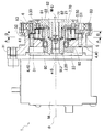
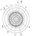
以下、図1乃至図5に基づき、実施形態1について説明する。図1に、本実施形態の遊星歯車機構が採用された減速装置を示す。本実施形態では、入力軸2に入力されたモータMの駆動力が、減速されて出力軸7に出力される減速装置1を示した。なお、入力軸の回転と歯車の位相を示すために、図1中のA−A断面を図2に、図1中のB−B断面を図3にそれぞれ示した。
<Embodiment 1>
The first embodiment will be described below with reference to FIGS. FIG. 1 shows a speed reducer employing the planetary gear mechanism of the present embodiment. In the present embodiment, the speed reduction device 1 in which the driving force of the motor M input to the
本実施形態の減速装置1は、モータM、ハウジングH、入力軸2、揺動面板3、第1ピン4、第2ピン5、内歯歯車6、出力軸7、を有する。
The speed reducer 1 of this embodiment includes a motor M, a housing H, an
モータM(本発明の電動モータに該当する)は、回転を出力する部材である。本実施形態においてモータMは、特に限定されるものではない。 The motor M (corresponding to the electric motor of the present invention) is a member that outputs rotation. In the present embodiment, the motor M is not particularly limited.
ハウジングH(本発明の第1部材に該当する)は、モータMに固定され、減速装置1の外周形状の一部を形成する部材である。また、ハウジングHは、モータMの回転軸MJ、入力軸2(本発明の第3部材および第1軸に該当する)、揺動面板3(本発明の揺動部材に該当する)、第1ピン4、第2ピン5、内歯歯車6、出力軸7(内歯歯車6を含んだ構成が、本発明の第2部材および第2軸に該当する)等の部材を、回転可能な状態で収容・支持する部材である。ハウジングHは、入力軸2と出力軸7とを、両軸線(入出力軸線であり図においてφにて示す)が一致して共通となる状態で回転可能に支持する。
The housing H (corresponding to the first member of the present invention) is a member that is fixed to the motor M and forms a part of the outer peripheral shape of the reduction gear 1. The housing H includes a rotating shaft MJ of the motor M, an input shaft 2 (corresponding to a third member and a first shaft of the present invention), a swinging face plate 3 (corresponding to a swinging member of the present invention), a first A state in which members such as the
入力軸2は、モータMの回転軸MJに固定された略筒状の部材である。入力軸2は、モータMの回転軸MJに外挿固定された縮径部20と、縮径部20の先端側に位置し縮径部20よりも内径と外径が拡径した筒状の拡径部21と、を有している。なお、縮径部20と拡径部21の径の変化は、図1に示したように、徐々に(階段状に)内径及び外径が変化するように形成されている。
The
縮径部20は、ハウジングHとの間に入力軸支持軸受け80を介して、回転可能な状態で配されている。
The reduced diameter portion 20 is disposed in a rotatable state between the housing H and the input
拡径部21は、径方向の外周面が、入力軸2の軸心に対して偏心した偏心形状をなす偏心部22を備えている。つまり、入力軸2が入出力軸線を中心に回転すると、偏心部22も入出力軸線を中心として回転をし、偏心部22の外周面を揺動させる。偏心部22の外周面は、入出力軸線に対して異なる位置にある偏心軸(図においてeφにて示す)を中心とした真円状に形成されている。
The
入力軸2は、縮径部20のハウジングHに支持された部分よりもモータMに近接した位置に、カウンターバランサ23が設けられている。カウンターバランサ23は、偏心部22により生じるアンバランス回転を打ち消すように配されている。具体的には、カウンターバランサ23は、図4に示したように、偏心部22の偏心形状と逆の位相となるように組み付けられている。なお、図4は、出力軸7側からモータM方向を見たときに、揺動面板3とカウンターバランサ23との位相差がわかるように示した概略図である。
The
揺動面板3は、揺動部材支持軸受け81を介して拡径部21(の偏心部22)に外挿された円盤状の部材である。本実施形態において、揺動面板3は、揺動部材支持軸受け81を介して拡径部21(の偏心部22)に外挿される筒状部30と、筒状部30のモータMに近接する側の端部で軸方向に垂直に広がる円盤状の円盤部31と、を有する。筒状部30、すなわち揺動面板3(揺動部材)は、揺動部材支持軸受け81を介して、偏心部22により支持されている。揺動面板3には、外周面において、ハウジングHに形成された入出力軸を中心とする第1内歯歯車に係合する第1外歯歯車32と、第2内歯歯車6と係合する第2外歯歯車と、が形成されている。揺動面板3は、偏心軸に対して回転すると共に、それぞれの内歯歯車と外歯歯車との係合により偏心軸が入出力軸線の回りを回転する。
The
揺動面板3の円盤部31の端部には、周方向に沿ってエピトロコイド型の外歯歯車32が、所定のピッチ(本実施形態では歯数が29)で形成されている。この外歯歯車32は、本発明の第1外歯歯車に相当する。
At the end of the
また、揺動面板3の円盤部31には、複数本(本実施形態では23本)の第2ピン5が等間隔(等ピッチ)で固定されている。第2ピン5は、揺動面板3の円盤部31の一方の表面に、モータMから離れる方向(入出力軸線方向)に突出して固定されている。このピン5により、本発明の第2外歯歯車に相当する外歯歯車が形成されている。
A plurality of (23 in this embodiment)
第2ピン5は、図1に示したように、揺動面板3に固定された円柱状のピン本体50と、ピン本体50に回転可能な状態で外挿された円筒状のカラー51と、から構成される。
As shown in FIG. 1, the
揺動面板3の円盤部31の外歯歯車32は、その円周上の一部のみが内歯歯車に噛合している。この内歯歯車は、本発明の第1内歯歯車に相当する。内歯歯車は、ハウジングHに固定された第1ピン4により内周面に形成される。第1ピン4は、入力軸2及び出力軸7の軸方向と平行(入出力軸線方向)にのびた状態で固定されている。第1ピン4は、複数本(本実施形態では、噛み合う外歯の歯数より1本多い30本)が、等間隔(等ピッチ)で固定されている。第1ピン4は、揺動面板3が揺動回転運動をしたときに、円盤部31の端部に形成された外歯歯車32と係合する(噛み合う)。外歯歯車32(第1外歯歯車)と第2ピン5による第2外歯歯車は、いずれも偏心軸を中心として形成され、互いに同軸上に設けられている。
As for the
第1ピン4は、図1に示したように、ハウジングHに固定された円柱状のピン本体40と、ピン本体40に回転可能な状態で外挿された円筒状のカラー41と、から構成される。
As shown in FIG. 1, the
揺動面板3の円盤部31に固定された第2ピン5の径方向外方(円盤部31の遠心方向)には、第2ピン5により形成された外歯歯車に、その円周上の一部のみが内接噛合する内歯歯車6が形成されている。内周面に歯を有する内歯歯車6は、本発明の第2内歯歯車に相当する。内歯歯車6は、出力軸7に固定されている。内歯歯車6は、ハイポトロコイド型の内歯が所定のピッチ(本実施形態では歯数が、噛み合う外歯の歯数より1本多い24)で形成されている。
On the outer side in the radial direction of the
出力軸7は、円盤状の円盤状部70と、円盤状部70からモータMに近接する方向に突出した入力軸2の拡径部21の軸心に挿入される挿入部71と、から構成される。出力軸7は、ハウジングHに、出力軸支持軸受け83により入出力軸線を中心に回転可能な状態で支持されている。
The
出力軸7(第2部材)は、挿入部71が入力軸2(第3部材)の拡径部21の軸心に挿入されているが、この挿入部71は、拡径部21の内周面に対して第2部材支持軸受け82を介して支持されている。
In the output shaft 7 (second member) , the
つづいて、本実施形態の減速装置1の動作を説明する。
まず、モータMを作動させる。モータMの回転軸MJを介して入力軸2が回転する。入力軸2が回転すると、入力軸2を構成する偏心部22が回転し、その外周面が揺動する(偏心回転)。このとき、入力軸2には、カウンターバランサ23が設けられているため、偏心部22が偏心回転により生じる回転のアンバランスが打ち消される。
Next, the operation of the reduction gear 1 according to the present embodiment will be described.
First, the motor M is operated. The
偏心部22の偏心回転は、揺動部材支持軸受け81を介して揺動面板3を偏心揺動させるとともに、偏心軸を中心に回転運動(偏心揺動運動)させる。このとき、揺動面板3は、円盤部31の外周にエピトロコイド型の外歯が形成されており、外歯歯車の円周上の一部のみが第1ピン4と噛合する。揺動面板3はハウジングHに対して揺動し、この外歯と、ハウジングHに固定された第1ピン4とが噛合する円周上の位置が移動することで、揺動面板3は、偏心軸を中心として入力軸2の回転方向とは反対方向に、減速されて回転される。なお、減速比は、噛み合う歯車の歯数により決定される。
The eccentric rotation of the
そして、回転が減速した揺動面板3には、第2ピン5が固定されており、それぞれの第2ピン5は、揺動面板3とともに偏心揺動回転する。第2ピン5は、内歯歯車6とその円周上の一部のみが噛み合っており、この第2ピン5と、内歯歯車6とが噛合する円周上の位置が移動することで、その歯数差により、回転速度が(相対的に)減速される。このことは、上記の第1外歯歯車と第1内歯歯車とからなる第1歯車群における減速と同様である。
And the
そして、第2ピン5が揺動面板3に固定されており、減速された回転は、内歯歯車6を入出力軸線を中心に揺動面板3の回転方向とは反対方向に回転させる。この回転は、内歯歯車6が固定された出力軸7に伝達され、出力軸7により揺動面板3の回転をさらに減速した、入力軸2の回転方向と同方向の回転として取り出される。
The
このように、本実施形態の減速装置1は、入力軸2の回転を二つの歯車群で変速し、出力軸7から取り出す。そして、二つの歯車群のそれぞれにおいて、高い減速比で減速でき、その結果として、より高い減速比で出力回転を得られる。すなわち、本発明の減速装置1は、小型で高トルクで高減速比の減速装置となっている。
Thus, the reduction gear 1 of the present embodiment shifts the rotation of the
本実施形態の減速装置1は、揺動面板3にもうけられた外歯歯車32と、内歯歯車の当接面を形成する第1ピン4と、揺動面板3に固定された第2ピン5と、内歯歯車6の噛合面のみに高い加工精度が要求される。すなわち、それ以外の部分に高い加工精度が要求されなくなっている。つまり、加工コストを低減できる効果を発揮する。
The speed reduction device 1 of the present embodiment includes an
さらに、従来の遊星歯車機構では外歯歯車に内ピンを貫通する内ピン穴が必要となっており、外歯歯車自身の外径の縮径に限界があったが、本発明の遊星歯車機構は揺動面板(外歯歯車と同等に機能する)に二つの外歯歯車を設けることで、内ピン穴のような大きなスペースを要求する部品を用いなくなっている。この結果、外径を小型化できる効果を発揮する。 Furthermore, in the conventional planetary gear mechanism, the external gear requires an inner pin hole that penetrates the inner pin, and there is a limit to the reduction in the outer diameter of the external gear itself. By providing two external gears on the rocking face plate (which functions in the same way as an external gear), parts that require a large space such as an internal pin hole are no longer used. As a result, the effect of reducing the outer diameter is exhibited.
本実施形態の減速装置1では、二つの外歯歯車が同軸な状態で一つの揺動面板3に形成されたことで、同じ偏心揺動回転を生じる。このため、簡単な構成とすることができ、部品点数の増加を抑えることができる効果を発揮する。
In the reduction gear 1 of the present embodiment, the two eccentric gears are coaxially formed on one oscillating
また、本実施形態の減速装置1の遊星歯車機構では、入力軸2がモータM側に偏心部22のアンバランス回転を打ち消すカウンターバランサ23を有したことで、偏心部22により生じたアンバランス回転をこのカウンターバランサ23で打ち消している。すなわち、本実施形態の減速装置1の遊星歯車機構では、減速装置1が振動することが抑えられている。さらに、本実施形態の減速装置1の遊星歯車機構では、簡単な形状のカウンターバランサ23を用いることができることから、加工コストを低減できる効果を発揮する。
Further, in the planetary gear mechanism of the reduction gear 1 of the present embodiment, the
また、本実施形態の減速装置1の遊星歯車機構では、第1ピン4,第2ピン5が、相手歯車32,6等の歯車と噛合う噛合面が、ピン本体40,50に外挿されたカラー41,51により形成されており、第1ピン4,第2ピン5と相手歯車32,6とが噛合した時に、歯面の滑りをカラー41,51の回転により吸収することができ、高効率での噛み合いを達成できる。
In the planetary gear mechanism of the speed reducer 1 according to the present embodiment, the meshing surfaces of the
さらに、本実施形態の減速装置1の遊星歯車機構では、カラー41,51の外径を調節することで、噛み合いのバックラッシュを簡単に調節することができる。つまり、加工コストを低減できる効果を発揮する。
Furthermore, in the planetary gear mechanism of the reduction gear 1 of the present embodiment, the mesh backlash can be easily adjusted by adjusting the outer diameters of the
加えて、本実施形態の減速装置1の遊星歯車機構では、二つの歯車群において、それぞれの内歯歯車が噛合する相手歯車から受ける径方向内方に向かう反力は、揺動面板3,揺動部材支持軸受け81,入力軸2の拡径部21,第2部材支持軸受け82を介して出力軸7の挿入部71にかかる。つまり、各歯車群において内歯歯車4,6と外歯歯車32,5とが噛み合う力がロスなく用いられる。
In addition, in the planetary gear mechanism of the reduction gear 1 according to the present embodiment, in the two gear groups, the reaction force directed inward in the radial direction from the mating gear with which the respective internal gear meshes is generated by the rocking
(減速比)
第1実施形態においては、第1外歯歯車(揺動面板3の円盤部31の外周の歯車32)、第1内歯歯車(ピン4により形成される歯車)、第2外歯歯車(ピン5により形成される歯車)、第2内歯歯車(内歯歯車6)のそれぞれの歯数は、表1に示した通りである。

In the first embodiment, the first external gear (the
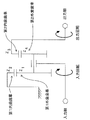
第1実施形態の減速装置1の減速機構を模式的に示すと、図5に示した通りとなる。そして、それぞれの歯数から減速比を求めると、下記数式の通りとなる。 A speed reduction mechanism of the speed reduction device 1 according to the first embodiment is schematically shown in FIG. And if the reduction ratio is calculated | required from each number of teeth, it will become as the following numerical formula.
なお、z2は第1内歯歯車の歯数、z1は第1外歯歯車の歯数、z4は第2外歯歯車の歯数、z3は第2内歯歯車の歯数である。また、ninは入力軸2の回転数、noutは出力軸7の回転数である。
Here, z2 is the number of teeth of the first internal gear, z1 is the number of teeth of the first external gear, z4 is the number of teeth of the second external gear, and z3 is the number of teeth of the second internal gear. Further, n in is the rotational speed of the
第1実施形態の減速装置1は、表1に示したそれぞれの歯車の歯数から116.00と高い減速比でモータMの回転を減速できることが確認できる。 It can be confirmed that the reduction gear 1 of the first embodiment can reduce the rotation of the motor M at a high reduction ratio of 116.00 from the number of teeth of each gear shown in Table 1.
第1実施形態の減速装置1において、第2外歯歯車と第2内歯歯車の歯数をそれぞれ一つずつ大きなものとすると(z3を25に、z4を24にすると)、減速比は145.00と、第1実施形態の場合よりも更に大きくなる。表1に第1変形形態例として併せて示した。 In the reduction gear 1 of the first embodiment, if the number of teeth of each of the second external gear and the second internal gear is increased by one (when z3 is 25 and z4 is 24), the reduction ratio is 145. .00, which is larger than that of the first embodiment. Table 1 also shows the first modified embodiment.
また、第1変形形態例から、第1外歯歯車と第1内歯歯車の歯数をそれぞれ一つずつ小さなものに替えるとともに、第2外歯歯車と第2内歯歯車の歯数をそれぞれ一つずつ大きなものとすると(z1を28に、z2を29に、z3を26に、z4を25にすると)、減速比は242.67と、更に大きくなる。表1に第2変形形態例として併せて示した。 In addition, from the first modification, the number of teeth of the first external gear and the first internal gear is changed to a smaller one each, and the number of teeth of the second external gear and the second internal gear is respectively changed. If it is made larger one by one (when z1 is 28, z2 is 29, z3 is 26, and z4 is 25), the reduction ratio is further increased to 242.67. Table 1 also shows a second modified example.
上記のように、本実施形態の減速装置1の遊星歯車機構では、各歯車の歯数を変更することで、簡単に減速比を調節することができる。すなわち、簡単な構成でありながら、高い減速比を達成できる効果を発揮できる。 As described above, in the planetary gear mechanism of the reduction gear 1 of the present embodiment, the reduction ratio can be easily adjusted by changing the number of teeth of each gear. That is, the effect of achieving a high reduction ratio can be exhibited with a simple configuration.
なお、各歯車群を構成する各歯車のそれぞれの歯数は、特に限定されるものではなく、減速装置1において求められている減速比が得られる歯数の組み合わせを適宜選択できる。 The number of teeth of each gear constituting each gear group is not particularly limited, and a combination of the number of teeth capable of obtaining the reduction ratio required in the reduction gear device 1 can be appropriately selected.
<実施形態1の変形形態>
上記の実施形態においては、第1外歯歯車及び第2内歯歯車をトロコイド型の歯車で、第1内歯歯車及び第2外歯歯車をピンにより形成していたが、各歯車のそれぞれにおいては、ピンとトロコイド型の歯車とが噛み合う組み合わせならば、下記表2に示した組み合わせのいずれでもよい。
In the above embodiment, the first external gear and the second internal gear are formed by trochoid gears, and the first internal gear and the second external gear are formed by pins. As long as the pin and the trochoidal gear mesh with each other, any of the combinations shown in Table 2 below may be used.
上記したように、各実施形態の減速装置1は、モータMの回転を体格が小さな装置で減速している。すなわち、本発明の遊星歯車機構は、特に、小型のロボット等において用いることが好ましい。 As described above, in the speed reduction device 1 of each embodiment, the rotation of the motor M is reduced by a device having a small physique. That is, the planetary gear mechanism of the present invention is particularly preferably used in a small robot or the like.
<実施形態1の別の変形形態>
上記の実施形態においては、本発明の歯車機構を、入力軸2に入力されたモータMの駆動力が、減速されて出力軸7に出力される減速装置1に適用した例を示したが、出力軸7に入力された駆動力が、増速されて入力軸2に出力される増速装置に適用してもよい。
<Another Variation of Embodiment 1>
In the above embodiment, the gear mechanism of the present invention is applied to the reduction gear 1 in which the driving force of the motor M input to the
<実施形態2>
次に、図6乃至図9に基づき、実施形態2による減速装置1Kについて、上述した減速装置1との相違点のみを説明する。図6に示すように、モータM1(本発明の電動モータに該当する)のケースC1(本発明の第1部材に該当する)は、減速装置1Kのハウジングと一体的に形成されている。ケースC1は、減速装置1Kのハウジングを兼ねており、出力軸支持軸受け803を介して出力軸700(本発明の第2部材に該当する)を回転可能に支持している。出力軸支持軸受け803の内輪は、出力軸700と一体的に形成されている。
<
Next, based on FIG. 6 thru | or FIG. 9, only the difference with the reduction gear 1 mentioned above about the
また、モータM1からはアウトプットシャフト200(本発明の第3部材および電動モータの出力軸に該当する)が突出しており、アウトプットシャフト200は減速装置1Kの入力軸を兼ねるべく、入力軸と一体的に形成されている。アウトプットシャフト200の先端部には、入出力軸線(図においてφにて示す)に対して外周面が偏心した偏心部202が形成されている。偏心部202の半径方向内方部には、出力軸700(第2部材)の挿入部701が挿入されており、偏心部202の内周面と挿入部701との間には第2部材支持軸受け802が介装されている。
Further, an output shaft 200 (corresponding to the third member of the present invention and the output shaft of the electric motor) protrudes from the motor M1, and the
アウトプットシャフト200には、アウトプットシャフト200の偏心部202により生じたアンバランス回転を打ち消すために、カウンターバランサ203が形成されている。カウンターバランサ203は、アウトプットシャフト200を部分的に刳り抜いた軽量孔により形成されている。軽量孔は、偏心部202において、外周面が入出力軸線を中心として外方へ突出しているため重量が大きい部位と、同じ円周上の位置に形成されている(図7示)。
A
アウトプットシャフト200の偏心部202の外周面には、揺動部材支持軸受け801を介して揺動面板300が支持されている。揺動面板300(本発明の揺動部材に該当する)は、入出力軸線を中心としたアウトプットシャフト200の回転により、偏心部202とともに揺動可能に形成されている。
A rocking
揺動面板300の外周部の一側の側面からは、23個の第1ピン400がモータM1に向けて入出力軸線方向に突出している。第1ピン400の先端部にはカラー401が装着されている。第1ピン400の先端部は、実施形態1のものと同様の第1外歯歯車を形成している(図8示)。
From the side surface on one side of the outer peripheral portion of the
モータM1のケースC1には、半径方向内方へと延びた支持部C1aが形成され、支持部C1aの内周面には、実施形態1のものと同様の内歯歯車C1bが設けられている。内歯歯車C1bは、第1外歯歯車よりも1歯多い24の歯を備えており、実施形態1のものと同様のハイポトロコイド型の第1内歯歯車を形成している。内歯歯車C1bの円周上の一部は、カラー401を介して、第1ピン400の先端部と噛合している(第1歯車群を形成している)。
A support portion C1a extending radially inward is formed in the case C1 of the motor M1, and an internal gear C1b similar to that of the first embodiment is provided on the inner peripheral surface of the support portion C1a. . The internal gear C1b includes 24 teeth, one more than the first external gear, and forms a hypotrochoid first internal gear similar to that of the first embodiment. A part of the circumference of the internal gear C1b meshes with the tip of the
一方、出力軸700の一側の側面からは、30個の第2ピン500がモータM1に向けて入出力軸線方向に突出している。第2ピン500の先端部にはカラー501が装着されている。第2ピン500の先端部は、半径方向において、揺動面板300の外周端と対向するように位置しており、実施形態1のものと同様の第2内歯歯車を形成している(図9示)。
On the other hand, from the side surface on one side of the
また、揺動面板300の外周面には、実施形態1のものと同様のエピトロコイド型の外歯歯車302が設けられている。外歯歯車302は、第2内歯歯車よりも1歯少ない29個の歯を備えており、実施形態1のものと同様の第2外歯歯車を形成している。外歯歯車302の円周上の一部は、カラー501を介して、第2ピン500の先端部と噛合している(第2歯車群を形成している)。
An epitrochoid
その他の構成については、実施形態1による減速装置1と同様であるため、これ以上の説明は省略する。 Since other configurations are the same as those of the reduction gear 1 according to the first embodiment, further description thereof is omitted.
次に、減速装置1Kの動作を説明する。モータM1を作動させると、アウトプットシャフト200が回転する。アウトプットシャフト200が回転すると、アウトプットシャフト200を構成する偏心部202が偏心回転する。偏心部202の偏心回転は、揺動部材支持軸受け801を介して揺動面板300を揺動運動(偏心揺動運動)させるとともに、偏心軸を中心に揺動面板300を回転させる。
Next, the operation of the
揺動面板300が揺動しながら回転運動すると、揺動面板300にもうけられた第1外歯歯車および第2外歯歯車も揺動しながら回転運動する。このとき、第1ピン400(第1外歯歯車)の円周上の一部のみが内歯歯車C1b(第1内歯歯車)と噛合しており、揺動面板300の揺動および回転運動により、第1外歯歯車と第1内歯歯車とが噛合する円周上の位置が移動することで、揺動面板300が偏心軸を中心に回転する回転速度が減速される。揺動面板300は、アウトプットシャフト200とは反対方向に回転する。なお、減速比は、第1外歯歯車と第1内歯歯車とが噛み合う歯車の歯数により決定される。
When the swinging
そして、回転が減速した揺動面板300には、外歯歯車302(第2外歯歯車)が形成されており、揺動面板300とともに偏心揺動回転する。外歯歯車302は第2ピン500(第2内歯歯車)と噛合しており、この第2ピン500と、外歯歯車302とが噛合する円周上の位置が移動することで、その歯数差により、第2ピン500が設けられた出力軸700の回転速度が(相対的に)減速される。このことは、上記の第1外歯歯車と第1内歯歯車とからなる第1歯車群における減速と同様である。出力軸700は、揺動面板300とは反対方向に回転する。この結果、出力軸700において、入出力軸線を中心としてさらに減速された回転が取り出される。
An external gear 302 (second external gear) is formed on the
実施形態2によれば、第1外歯歯車は揺動面板300から突出した第1ピン400により形成されたことにより、これと噛合する第1内歯歯車をケースC1に切削により形成することができるため、第1内歯歯車を設ける場合に、ハウジングとしてのケースC1の壁(支持部C1a)を貫通切削することにより形成することができ、その製造が容易となる。
According to the second embodiment, since the first external gear is formed by the
また、第2内歯歯車は出力軸700から突出した第2ピン500により形成されたことにより、出力軸700に第2内歯歯車を形成する場合に、出力軸700を袋状に加工する必要がなく、その製造が容易となる。
Further, since the second internal gear is formed by the
また、カウンターバランサ203がアウトプットシャフト200を部分的に刳り抜いた軽量孔であることにより、部品点数を増やすことなく、アウトプットシャフト200の偏心アンバランス荷重を解消することができる。
Further, since the
また、出力軸支持軸受け803の内輪を出力軸700と一体に形成したことにより、部品点数を低減し、低コストの遊星歯車機構にすることができる。
Further, since the inner ring of the output shaft support bearing 803 is formed integrally with the
また、モータM1のケースC1が減速装置1Kのハウジングと一体的に形成され、モータM1のアウトプットシャフト200と減速装置1Kの入力軸とが一体的に形成されたことにより、実施形態1に示した入力軸支持軸受け80を廃止することができ、部品点数を低減し、低コストの減速装置1Kにすることができる。
In addition, the case C1 of the motor M1 is formed integrally with the housing of the
<実施形態2の変形形態>
出力軸支持軸受け803の内輪は、必ずしも出力軸700と一体的に形成する必要はなく、出力軸700に対して独立して内輪を設けてもよい。
<Modification of
The inner ring of the output shaft support bearing 803 is not necessarily formed integrally with the
減速装置1Kにおいて、出力軸700を回転不能に固定するとともに、ケースC1を入出力軸線を中心に回転可能にしてもよい。また、出力軸700およびケースC1をともに入出力軸線を中心に回転可能にし、それぞれに所定の比率で減速回転を出力してもよい。
In the
実施形態1による減速装置1において、入力軸2にカウンターバランサ23としての軽量孔を設けてもよい。
In the reduction gear 1 according to the first embodiment, the
実施形態1による減速装置1において、出力軸支持軸受け83の内輪を出力軸7と一体的に形成してもよい。
In the reduction gear 1 according to the first embodiment, the inner ring of the output shaft support bearing 83 may be formed integrally with the
実施形態1による減速装置1において、入力軸2をモータMの回転軸MJと一体に形成し、ハウジングHをモータMのケースと一体に形成してもよい。
In the reduction gear 1 according to the first embodiment, the
1,1K:減速装置
2:入力軸 20:縮径部
21:拡径部 22,202:偏心部
23,203:カウンターバランサ
3,300:揺動面板 30:筒状部
31:円盤部 32,302:外歯歯車
4,400:第1ピン 40:ピン本体
41,401:カラー
5,500:第2ピン 50:ピン本体
51,501:カラー
6,C1b:内歯歯車
7,700:出力軸 70:円盤状部
71,701:挿入部
80:入力軸支持軸受け 81,801:揺動部材支持軸受け
82,802:第2部材支持軸受け
83,803:出力軸支持軸受け
200:アウトプットシャフト
C1:ケース
M,M1:モータ
φ:入出力軸線 eφ:偏心軸
1, 1K: Deceleration device 2: Input shaft 20: Reduced diameter portion 21:
Claims (18)
内周面に第2内歯歯車が形成されるとともに、入出力軸線を中心に前記第1部材に対して相対回転可能な第2部材と、
環状に形成され、外周面に前記第1内歯歯車と噛合可能な第1外歯歯車および前記第2内歯歯車と噛合可能な第2外歯歯車を備え、前記第1外歯歯車の歯数は前記第1内歯歯車の歯数よりも少なく、前記第2外歯歯車の歯数は前記第2内歯歯車の歯数よりも少なく形成されており、前記第1部材および前記第2部材に対して揺動することにより、前記第1外歯歯車の円周上の一部のみが前記第1内歯歯車と噛合し、前記第2外歯歯車の円周上の一部のみが前記第2内歯歯車と噛合するように形成された揺動部材と、
前記入出力軸線に対して偏心した外周面を有する偏心部を備えるとともに、前記偏心部が前記揺動部材の内周面を支持し前記入出力軸線を中心に回転することによって前記揺動部材を揺動させる、または、前記揺動部材が揺動することにより前記入出力軸線を中心に回転させられる第3部材と、
を備え、
前記第3部材に駆動力を入力して前記揺動部材を揺動させるとともに回転させ、前記第1外歯歯車と前記第1内歯歯車とが噛合する円周上の位置および前記第2外歯歯車と前記第2内歯歯車とが噛合する円周上の位置を移動させることにより、前記第1部材および前記第2部材のうちの少なくとも一方に減速された駆動力を出力させる、
または、
前記第1部材および前記第2部材のうちの少なくとも一方に駆動力を入力して、前記第1外歯歯車と前記第1内歯歯車とが噛合する円周上の位置および前記第2外歯歯車と前記第2内歯歯車とが噛合する円周上の位置を移動させ、前記揺動部材を揺動させるとともに回転させることにより、前記第3部材に増速された駆動力を出力させ、
前記第2部材は、その一部が前記第3部材の軸心部に内挿され、
該第3部材と、該第2部材の該第3部材に内挿された部分の間には、第2部材支持軸受けが配されていることを特徴とする遊星歯車機構。 A first member having a first internal gear formed on the inner peripheral surface;
A second internal gear is formed on the inner peripheral surface, and a second member rotatable relative to the first member around the input / output axis;
A first external gear that is formed in an annular shape and that can mesh with the first internal gear and a second external gear that can mesh with the second internal gear are provided on the outer peripheral surface, and the teeth of the first external gear The number of teeth is smaller than the number of teeth of the first internal gear, the number of teeth of the second external gear is smaller than the number of teeth of the second internal gear, and the first member and the second By swinging with respect to the member, only a part on the circumference of the first external gear meshes with the first internal gear, and only a part on the circumference of the second external gear. A swinging member formed to mesh with the second internal gear;
An eccentric portion having an outer peripheral surface that is eccentric with respect to the input / output axis is provided, and the eccentric portion supports an inner peripheral surface of the swing member and rotates about the input / output axis to thereby rotate the swing member. A third member that is swung or rotated about the input / output axis when the swinging member swings;
With
A driving force is input to the third member to cause the swinging member to swing and rotate so that the first external gear and the first internal gear mesh with each other on the circumference and the second external gear. By moving a circumferential position where the toothed gear and the second internal gear mesh with each other, to output a reduced driving force to at least one of the first member and the second member;
Or
A driving force is input to at least one of the first member and the second member, and a position on the circumference where the first external gear and the first internal gear mesh with each other, and the second external tooth By moving a position on the circumference where the gear and the second internal gear mesh with each other, and swinging and rotating the swing member, the driving force increased in speed is output to the third member,
A part of the second member is inserted into the axial center of the third member,
A planetary gear mechanism, wherein a second member support bearing is disposed between the third member and a portion of the second member inserted into the third member.
前記第1外歯歯車と前記第1内歯歯車の一方は、前記入出力軸線方向に伸びる第1ピンよりなることを特徴とする遊星歯車機構。 In claim 1,
One of the first external gear and the first internal gear comprises a first pin extending in the input / output axis direction, and a planetary gear mechanism.
前記第2外歯歯車と前記第2内歯歯車の一方は、前記入出力軸線方向に伸びる第2ピンよりなることを特徴とする遊星歯車機構。 In any one of Claims 1-2,
One of said 2nd external gear and said 2nd internal gear consists of the 2nd pin extended in the said input-output axial direction, The planetary gear mechanism characterized by the above-mentioned.
各前記外歯歯車と各前記内歯歯車の他方は、トロコイド歯形で形成されていることを特徴とする遊星歯車機構。 In any one of Claims 2-3,
The planetary gear mechanism characterized in that the other of the external gears and the other of the internal gears are formed in a trochoidal tooth profile.
前記第1外歯歯車の中心軸と前記第2外歯歯車の中心軸は、同軸に設けられていることを特徴とする遊星歯車機構。 In any one of Claims 1-4,
The planetary gear mechanism characterized in that the central axis of the first external gear and the central axis of the second external gear are provided coaxially.
前記第1ピンは、ピン本体と、該ピン本体に回転可能な状態で外装されたカラーと、を有することを特徴とする遊星歯車機構。 In claim 2,
The first pin includes a pin main body and a collar that is rotatably mounted on the pin main body.
前記第2ピンは、ピン本体と、該ピン本体に回転可能な状態で外装されたカラーと、を有することを特徴とする遊星歯車機構。 In claim 3,
The planetary gear mechanism, wherein the second pin has a pin main body and a collar that is rotatably mounted on the pin main body.
前記偏心部と前記揺動部材との間には揺動部材支持軸受けが配されていることを特徴とする遊星歯車機構。 In any one of Claims 1-7,
A planetary gear mechanism, wherein a swinging member support bearing is disposed between the eccentric portion and the swinging member.
前記第2部材支持軸受けは、前記第3部材の前記偏心部と、前記第2部材の該第3部材に内挿された部分の間に配されていることを特徴とする遊星歯車機構。 In any one of Claims 1-8,
The planetary gear mechanism, wherein the second member support bearing is disposed between the eccentric portion of the third member and a portion of the second member inserted into the third member.
前記第3部材を入力軸とし、前記第2部材を出力軸とする減速機構であることを特徴とする遊星歯車機構。 In any one of Claims 1-9,
A planetary gear mechanism, wherein the planetary gear mechanism is a speed reduction mechanism having the third member as an input shaft and the second member as an output shaft.
前記第1部材は、前記第2部材および前記第3部材を回転可能に支持するハウジングであって、
前記第2部材は、前記第3部材に入力された駆動力を減速して出力する出力軸であり、
前記第1内歯歯車は前記第1部材から突出した前記第1ピンにより形成され、前記第2外歯歯車は前記揺動部材から突出した前記第2ピンにより形成されたことを特徴とする遊星歯車機構。 In claims 2 and 3,
The first member is a housing that rotatably supports the second member and the third member,
The second member is an output shaft that decelerates and outputs the driving force input to the third member,
The first internal gear is formed by the first pin protruding from the first member, and the second external gear is formed by the second pin protruding from the swing member. Gear mechanism.
前記第1部材は、前記第2部材および前記第3部材を回転可能に支持するハウジングであって、
前記第2部材は、前記第3部材に入力された駆動力を減速して出力する出力軸であり、
前記第1外歯歯車は前記揺動部材から突出した前記第1ピンにより形成され、前記第2内歯歯車は前記第2部材から突出した前記第2ピンにより形成されたことを特徴とする遊星歯車機構。 In claims 2 and 3,
The first member is a housing that rotatably supports the second member and the third member,
The second member is an output shaft that decelerates and outputs the driving force input to the third member,
The first external gear is formed by the first pin protruding from the swing member, and the second internal gear is formed by the second pin protruding from the second member. Gear mechanism.
前記第3部材は、前記偏心部のアンバランス回転を打ち消すカウンターバランサを有することを特徴とする遊星歯車機構。 In any one of Claims 1-12,
The planetary gear mechanism, wherein the third member includes a counter balancer that cancels unbalanced rotation of the eccentric portion.
前記カウンターバランサは、前記第3部材を部分的に刳り抜いた軽量孔であることを特徴とする遊星歯車機構。 In claim 13,
The counter balancer is a lightweight hole in which the third member is partially hollowed out.
前記第2部材は出力軸支持軸受けを介して、前記第1部材により回転可能に支持されており、
前記出力軸支持軸受けの内輪を前記第2部材と一体に形成したことを特徴とする遊星歯車機構。 In any one of Claims 1-14,
The second member is rotatably supported by the first member via an output shaft support bearing ,
A planetary gear mechanism characterized in that an inner ring of the output shaft support bearing is formed integrally with the second member.
前記第3部材は、電動モータにより駆動され、
前記電動モータのケースは、前記第1部材または前記第2部材と一体的に形成され、
前記電動モータの出力軸と前記第3部材とが一体的に形成されたことを特徴とする遊星歯車機構。 In any one of Claims 1-15,
The third member is driven by an electric motor;
The case of the electric motor is formed integrally with the first member or the second member,
A planetary gear mechanism, wherein an output shaft of the electric motor and the third member are integrally formed.
前記入力軸および前記出力軸のうちの一方であって、前記入出力軸線に対して偏心した偏心軸を中心とする偏心部を有する第1軸と、
前記入力軸および前記出力軸のうちの他方であって、第2内歯歯車が設けられた第2軸と、
前記偏心部に支持される筒状部と、前記ハウジングに形成された前記入出力軸線を中心とする第1内歯歯車に係合する第1外歯歯車と、前記第2内歯歯車と係合する第2外歯歯車と、が形成され、前記第1外歯歯車の歯数は前記第1内歯歯車の歯数よりも少なく、前記第2外歯歯車の歯数は前記第2内歯歯車の歯数よりも少なく形成されており、前記偏心軸に対して回転するとともに、前記ハウジングおよび前記第2軸に対して揺動することにより、前記第1外歯歯車の円周上の一部のみが前記第1内歯歯車と噛合し、前記第2外歯歯車の円周上の一部のみが前記第2内歯歯車と噛合するように形成された揺動部材と、
を備えた遊星歯車機構において、
前記第1内歯歯車は、前記ハウジングから突出し前記入出力軸線方向に伸びる第1ピンよりなり、
前記第2外歯歯車は、前記揺動部材から突出し前記入出力軸線方向に伸びる第2ピンよりなり、
前記第1軸に駆動力を入力して前記揺動部材を揺動させるとともに回転させ、前記第1外歯歯車と前記第1内歯歯車とが噛合する円周上の位置および前記第2外歯歯車と前記第2内歯歯車とが噛合する円周上の位置を移動させることにより、前記第2軸に減速された駆動力を出力させる、
または、
前記第2軸に駆動力を入力して、前記第1外歯歯車と前記第1内歯歯車とが噛合する円周上の位置および前記第2外歯歯車と前記第2内歯歯車とが噛合する円周上の位置を移動させ、前記揺動部材を揺動させるとともに回転させることにより、前記第1軸に増速された駆動力を出力させ、
前記第2軸は、その一部が前記第1軸の軸心部に内挿され、
該第1軸と、該第2軸の該第1軸に内挿された部分の間には、第2部材支持軸受けが配されていることを特徴とする遊星歯車機構。 A fixed housing that rotatably supports the input shaft and the output shaft around a common input / output axis;
A first shaft having an eccentric portion centered on an eccentric shaft that is one of the input shaft and the output shaft and is eccentric with respect to the input / output axis;
A second shaft provided with a second internal gear, which is the other of the input shaft and the output shaft;
A cylindrical portion supported by the eccentric portion, a first external gear engaged with a first internal gear centered on the input / output axis formed in the housing, and a second internal gear A second external gear to be coupled, wherein the number of teeth of the first external gear is smaller than the number of teeth of the first internal gear, and the number of teeth of the second external gear is the second internal gear. The number of teeth is smaller than the number of teeth of the toothed gear, and rotates with respect to the eccentric shaft and swings with respect to the housing and the second shaft. A swinging member formed so that only a part thereof meshes with the first internal gear and only a part of the circumference of the second external gear meshes with the second internal gear;
In a planetary gear mechanism with
The first internal gear includes a first pin protruding from the housing and extending in the input / output axis direction,
The second external gear includes a second pin protruding from the swing member and extending in the input / output axis direction,
A driving force is input to the first shaft to cause the swinging member to swing and rotate, and a position on the circumference where the first external gear and the first internal gear mesh with each other and the second outer gear. By moving a position on the circumference where the toothed gear and the second internal gear mesh with each other, to output a reduced driving force to the second shaft,
Or
When a driving force is input to the second shaft, the circumferential position where the first external gear and the first internal gear mesh with each other, and the second external gear and the second internal gear are By moving the meshing position on the circumference and swinging and rotating the rocking member, the increased driving force is output to the first shaft,
A part of the second axis is inserted into the axial center of the first axis,
A planetary gear mechanism, wherein a second member support bearing is disposed between the first shaft and a portion of the second shaft that is inserted into the first shaft.
前記入力軸および前記出力軸のうちの一方であって、前記入出力軸線に対して偏心した偏心軸を中心とする偏心部を有する第1軸と、
前記入力軸および前記出力軸のうちの他方であって、第2内歯歯車が設けられた第2軸と、
前記偏心部に支持される筒状部と、前記ハウジングに形成された前記入出力軸線を中心とする第1内歯歯車に係合する第1外歯歯車と、前記第2内歯歯車と係合する第2外歯歯車と、が形成され、前記第1外歯歯車の歯数は前記第1内歯歯車の歯数よりも少なく、前記第2外歯歯車の歯数は前記第2内歯歯車の歯数よりも少なく形成されており、前記偏心軸に対して回転するとともに、前記ハウジングおよび前記第2軸に対して揺動することにより、前記第1外歯歯車の円周上の一部のみが前記第1内歯歯車と噛合し、前記第2外歯歯車の円周上の一部のみが前記第2内歯歯車と噛合するように形成された揺動部材と、
を備えた遊星歯車機構において、
前記第1外歯歯車は、前記揺動部材から突出し前記入出力軸線方向に伸びる第1ピンよりなり、
前記第2内歯歯車は、前記第2軸から突出し前記入出力軸線方向に伸びる第2ピンよりなり、
前記第1軸に駆動力を入力して前記揺動部材を揺動させるとともに回転させ、前記第1外歯歯車と前記第1内歯歯車とが噛合する円周上の位置および前記第2外歯歯車と前記第2内歯歯車とが噛合する円周上の位置を移動させることにより、前記第2軸に減速された駆動力を出力させる、
または、
前記第2軸に駆動力を入力して、前記第1外歯歯車と前記第1内歯歯車とが噛合する円周上の位置および前記第2外歯歯車と前記第2内歯歯車とが噛合する円周上の位置を移動させ、前記揺動部材を揺動させるとともに回転させることにより、前記第1軸に増速された駆動力を出力させ、
前記第2軸は、その一部が前記第1軸の軸心部に内挿され、
該第1軸と、該第2軸の該第1軸に内挿された部分の間には、第2部材支持軸受けが配されていることを特徴とする遊星歯車機構。 A fixed housing that rotatably supports the input shaft and the output shaft around a common input / output axis;
A first shaft having an eccentric portion centered on an eccentric shaft that is one of the input shaft and the output shaft and is eccentric with respect to the input / output axis;
A second shaft provided with a second internal gear, which is the other of the input shaft and the output shaft;
A cylindrical portion supported by the eccentric portion, a first external gear engaged with a first internal gear centered on the input / output axis formed in the housing, and a second internal gear A second external gear to be coupled, wherein the number of teeth of the first external gear is smaller than the number of teeth of the first internal gear, and the number of teeth of the second external gear is the second internal gear. The number of teeth is smaller than the number of teeth of the toothed gear, and rotates with respect to the eccentric shaft and swings with respect to the housing and the second shaft. A swinging member formed so that only a part thereof meshes with the first internal gear and only a part of the circumference of the second external gear meshes with the second internal gear;
In a planetary gear mechanism with
The first external gear includes a first pin that protrudes from the swing member and extends in the input / output axis direction.
The second internal gear includes a second pin protruding from the second shaft and extending in the input / output axis direction,
A driving force is input to the first shaft to cause the swinging member to swing and rotate, and a position on the circumference where the first external gear and the first internal gear mesh with each other and the second outer gear. By moving a position on the circumference where the toothed gear and the second internal gear mesh with each other, to output a reduced driving force to the second shaft,
Or
When a driving force is input to the second shaft, the circumferential position where the first external gear and the first internal gear mesh with each other, and the second external gear and the second internal gear are By moving the meshing position on the circumference and swinging and rotating the rocking member, the increased driving force is output to the first shaft,
A part of the second axis is inserted into the axial center of the first axis,
A planetary gear mechanism, wherein a second member support bearing is disposed between the first shaft and a portion of the second shaft that is inserted into the first shaft.
Priority Applications (5)
| Application Number | Priority Date | Filing Date | Title |
|---|---|---|---|
| JP2010038737A JP5445216B2 (en) | 2009-06-30 | 2010-02-24 | Planetary gear mechanism |
| CN201080029022.0A CN102472367B (en) | 2009-06-30 | 2010-06-09 | Planetary gear mechanism |
| EP10793972.0A EP2450596B1 (en) | 2009-06-30 | 2010-06-09 | Planetary gear mechanism |
| PCT/JP2010/059776 WO2011001802A1 (en) | 2009-06-30 | 2010-06-09 | Planetary gear mechanism |
| US13/379,244 US8517878B2 (en) | 2009-06-30 | 2010-06-09 | Planetary gear mechanism |
Applications Claiming Priority (3)
| Application Number | Priority Date | Filing Date | Title |
|---|---|---|---|
| JP2009155812 | 2009-06-30 | ||
| JP2009155812 | 2009-06-30 | ||
| JP2010038737A JP5445216B2 (en) | 2009-06-30 | 2010-02-24 | Planetary gear mechanism |
Publications (3)
| Publication Number | Publication Date |
|---|---|
| JP2011027254A JP2011027254A (en) | 2011-02-10 |
| JP2011027254A5 JP2011027254A5 (en) | 2013-03-28 |
| JP5445216B2 true JP5445216B2 (en) | 2014-03-19 |
Family
ID=43410882
Family Applications (1)
| Application Number | Title | Priority Date | Filing Date |
|---|---|---|---|
| JP2010038737A Expired - Fee Related JP5445216B2 (en) | 2009-06-30 | 2010-02-24 | Planetary gear mechanism |
Country Status (5)
| Country | Link |
|---|---|
| US (1) | US8517878B2 (en) |
| EP (1) | EP2450596B1 (en) |
| JP (1) | JP5445216B2 (en) |
| CN (1) | CN102472367B (en) |
| WO (1) | WO2011001802A1 (en) |
Families Citing this family (23)
| Publication number | Priority date | Publication date | Assignee | Title |
|---|---|---|---|---|
| WO2014134765A1 (en) * | 2013-03-02 | 2014-09-12 | 浙江恒丰泰减速机制造有限公司 | Rigid internally and peripherally meshed speed reducer |
| KR101449392B1 (en) * | 2013-08-12 | 2014-10-08 | 삼보모터스주식회사 | Reducer |
| JP6079618B2 (en) * | 2013-12-27 | 2017-02-15 | 株式会社デンソー | Rotation drive |
| JP2016031080A (en) * | 2014-07-25 | 2016-03-07 | 武蔵精密工業株式会社 | Differential arrangement |
| US9476484B2 (en) * | 2014-11-07 | 2016-10-25 | Andrew Duerner | Oscillatory gearbox |
| JP6463212B2 (en) * | 2015-04-30 | 2019-01-30 | 国立大学法人東京工業大学 | Planetary roller drive type inscribed planetary gear reduction device |
| JP6461719B2 (en) * | 2015-06-08 | 2019-01-30 | 武蔵精密工業株式会社 | Transmission |
| US10371257B2 (en) * | 2015-11-30 | 2019-08-06 | Denso Corporation | Rotational drive apparatus and shift-by-wire system having the same |
| CN105508584A (en) * | 2016-02-01 | 2016-04-20 | 上海奇步机器人有限公司 | Planetary gear transmission with embedded bearing mechanism |
| DE112017000935B4 (en) * | 2017-05-12 | 2023-07-06 | Kunshan Quanta Machinery Co., Ltd. | Pin tooth cycloidal reducers and industrial robots |
| EP3483473A1 (en) * | 2017-11-14 | 2019-05-15 | Kimex Group s.r.o. | Gearbox |
| JP7211753B2 (en) * | 2017-12-08 | 2023-01-24 | ナブテスコ株式会社 | Gear unit and its assembly method |
| FR3085651B1 (en) * | 2018-09-10 | 2023-10-27 | Valeo Systemes Dessuyage | MECHANICAL REDUCER AND ASSOCIATED MOTOR-REDUCER |
| JP6815361B2 (en) * | 2018-10-10 | 2021-01-20 | 株式会社オリジン | Transmission combined with inscribed planetary gear mechanism |
| JP2020139535A (en) * | 2019-02-27 | 2020-09-03 | 日本電産シンポ株式会社 | Eccentric oscillation type transmission |
| CN113544393B (en) * | 2019-03-18 | 2024-09-10 | Ntn株式会社 | Electric actuator |
| JP7080339B2 (en) * | 2019-08-02 | 2022-06-03 | 株式会社Nittan | Decelerator |
| CN212509376U (en) * | 2020-02-27 | 2021-02-09 | 宁波瀚晟传动技术有限公司 | Transmission mechanism |
| CN113008549B (en) * | 2021-04-12 | 2023-07-21 | 宁波大学 | Variable-size RV reducer planetary gear stress measurement device and method |
| CN113883233B (en) * | 2021-10-15 | 2023-06-09 | 北京航空航天大学 | Planetary reducer based on flexible mechanism |
| CN114151514B (en) * | 2021-12-03 | 2023-07-21 | 广东博智林机器人有限公司 | Eccentric speed reducer and screw pump |
| CN114278705A (en) * | 2021-12-20 | 2022-04-05 | 宁波瀚晟传动技术有限公司 | Transmission mechanism |
| WO2024055866A1 (en) * | 2022-09-16 | 2024-03-21 | 美的集团股份有限公司 | Internally-meshing planetary gear device |
Family Cites Families (23)
| Publication number | Priority date | Publication date | Assignee | Title |
|---|---|---|---|---|
| US724663A (en) | 1901-01-18 | 1903-04-07 | Cahill & Hall Elevator Company | Elevator driving mechanism. |
| FR537465A (en) | 1920-11-30 | 1922-05-24 | Reduction device | |
| FR613071A (en) | 1925-07-07 | 1926-11-08 | Improvements to a speed reducer mounted directly on one of the bearings of an electric motor | |
| BE466957A (en) | 1945-09-03 | 1946-08-31 | Francesco Cicogna | Single-satellite epicyclic angular speed change |
| BE770716A (en) * | 1971-07-30 | 1971-12-01 | Soudure Autogene Elect | FRICTION FREE SPEED REDUCER WITH LARGE REDUCTION RATIO. |
| JPS4993765A (en) * | 1973-01-12 | 1974-09-06 | ||
| JPS5139299B2 (en) * | 1973-03-08 | 1976-10-27 | ||
| SE7904433L (en) * | 1979-05-21 | 1980-11-22 | Forenade Fabriksverken Ab | CYCLOID GEAR WITH NON-LAYING CURVES |
| US4604916A (en) * | 1984-02-10 | 1986-08-12 | Advanced Energy Concepts '81 Ltd. | Epicyclic transmission having cam driven roller retainer |
| JPS61136041A (en) * | 1984-12-03 | 1986-06-23 | Ntn Toyo Bearing Co Ltd | Speed reduction unit using trochoid tooth gear |
| JP3088990B2 (en) * | 1988-03-05 | 2000-09-18 | 帝人製機株式会社 | Driving device for rotating object |
| JPH0874947A (en) * | 1994-09-08 | 1996-03-19 | Tsubakimoto Chain Co | Planetary gear device |
| JPH0993765A (en) * | 1995-09-19 | 1997-04-04 | Sumitomo Wiring Syst Ltd | Clamp structure of a variety of equipment to bracket |
| SE515763C2 (en) * | 2000-02-22 | 2001-10-08 | Scandrive Control Ab | eccentric |
| JP4702505B2 (en) | 2000-05-25 | 2011-06-15 | ミネベア株式会社 | Gear device |
| JP2001336587A (en) | 2000-05-25 | 2001-12-07 | Minebea Co Ltd | Electro-motive actuator |
| JP4610108B2 (en) | 2001-03-08 | 2011-01-12 | 住友重機械工業株式会社 | Swing intermeshing planetary gear mechanism and angle transmission error reduction method |
| JP4818535B2 (en) | 2001-06-21 | 2011-11-16 | 住友重機械工業株式会社 | A transmission employing an eccentric oscillating internal meshing planetary gear structure |
| JP2003021198A (en) * | 2001-07-06 | 2003-01-24 | Sumitomo Heavy Ind Ltd | Transmission using epicyclic gear structure |
| KR200341272Y1 (en) * | 2003-09-08 | 2004-02-11 | 천기수 | A planetary gear reducer |
| JP2005254440A (en) * | 2004-02-13 | 2005-09-22 | Fanuc Ltd | Joint structure of industrial robot |
| EP2476931A1 (en) * | 2005-08-18 | 2012-07-18 | NTN Corporation | Power trasmission device |
| JP4993765B2 (en) | 2008-09-17 | 2012-08-08 | 日本アビオニクス株式会社 | Method and apparatus for soldering coated wire |
-
2010
- 2010-02-24 JP JP2010038737A patent/JP5445216B2/en not_active Expired - Fee Related
- 2010-06-09 WO PCT/JP2010/059776 patent/WO2011001802A1/en active Application Filing
- 2010-06-09 US US13/379,244 patent/US8517878B2/en not_active Expired - Fee Related
- 2010-06-09 CN CN201080029022.0A patent/CN102472367B/en not_active Expired - Fee Related
- 2010-06-09 EP EP10793972.0A patent/EP2450596B1/en not_active Not-in-force
Also Published As
| Publication number | Publication date |
|---|---|
| US20120100949A1 (en) | 2012-04-26 |
| EP2450596A1 (en) | 2012-05-09 |
| US8517878B2 (en) | 2013-08-27 |
| EP2450596B1 (en) | 2014-04-23 |
| JP2011027254A (en) | 2011-02-10 |
| CN102472367A (en) | 2012-05-23 |
| EP2450596A4 (en) | 2012-06-13 |
| CN102472367B (en) | 2015-05-20 |
| WO2011001802A1 (en) | 2011-01-06 |
Similar Documents
| Publication | Publication Date | Title |
|---|---|---|
| JP5445216B2 (en) | Planetary gear mechanism | |
| JP5477044B2 (en) | Planetary gear mechanism | |
| JP5533194B2 (en) | Transmission gear unit | |
| JP4267950B2 (en) | Internal gear swing type intermeshing planetary gear unit | |
| JP5828321B2 (en) | Transmission gear unit | |
| JP2011027254A5 (en) | ||
| JP2011027253A5 (en) | ||
| JP2001221298A (en) | Eccentric rotary reduction gear | |
| JPWO2008026571A1 (en) | Reduction gear | |
| JP2011212839A (en) | Structure of turning part of industrial robot using eccentric oscillation type reduction gear | |
| JP2018059556A (en) | Cycloid speed reducer reduced in backlash | |
| JP2023184669A (en) | gear unit | |
| JP2004286044A (en) | Internal gear swing type inner mesh planetary gear | |
| JP2015175380A (en) | Speed reducer and actuator | |
| JP2014005900A (en) | Eccentric rocking gear device | |
| WO2021171085A1 (en) | Transmission mechanism | |
| JP2011231801A (en) | Speed change gear | |
| JP2000280125A (en) | Manufacture of internal-tooth oscillating body of internal-tooth oscillating inscribed-meshing planetary gear | |
| JP2012246946A (en) | Rocking difference reduction gear | |
| WO2023238401A1 (en) | Planetary gear reducer | |
| JP6175298B2 (en) | Balance weight device | |
| JP7476070B2 (en) | Reduction gear and drive gear | |
| JP2016142402A (en) | Power transmission device | |
| JP2006297558A (en) | Pivoting part structure for industrial robot | |
| JP2018040381A (en) | Hypocycloid gear speed reduction device |
Legal Events
| Date | Code | Title | Description |
|---|---|---|---|
| A621 | Written request for application examination |
Free format text: JAPANESE INTERMEDIATE CODE: A621 Effective date: 20130122 |
|
| A521 | Request for written amendment filed |
Free format text: JAPANESE INTERMEDIATE CODE: A523 Effective date: 20130206 |
|
| A131 | Notification of reasons for refusal |
Free format text: JAPANESE INTERMEDIATE CODE: A131 Effective date: 20130924 |
|
| A521 | Request for written amendment filed |
Free format text: JAPANESE INTERMEDIATE CODE: A523 Effective date: 20131016 |
|
| TRDD | Decision of grant or rejection written | ||
| A01 | Written decision to grant a patent or to grant a registration (utility model) |
Free format text: JAPANESE INTERMEDIATE CODE: A01 Effective date: 20131126 |
|
| A61 | First payment of annual fees (during grant procedure) |
Free format text: JAPANESE INTERMEDIATE CODE: A61 Effective date: 20131209 |
|
| R150 | Certificate of patent or registration of utility model |
Free format text: JAPANESE INTERMEDIATE CODE: R150 |
|
| LAPS | Cancellation because of no payment of annual fees |