JP5437222B2 - Fuel cell stack - Google Patents
Fuel cell stack Download PDFInfo
- Publication number
- JP5437222B2 JP5437222B2 JP2010267952A JP2010267952A JP5437222B2 JP 5437222 B2 JP5437222 B2 JP 5437222B2 JP 2010267952 A JP2010267952 A JP 2010267952A JP 2010267952 A JP2010267952 A JP 2010267952A JP 5437222 B2 JP5437222 B2 JP 5437222B2
- Authority
- JP
- Japan
- Prior art keywords
- fuel cell
- cell stack
- stacking direction
- fuel
- gas supply
- Prior art date
- Legal status (The legal status is an assumption and is not a legal conclusion. Google has not performed a legal analysis and makes no representation as to the accuracy of the status listed.)
- Expired - Fee Related
Links
- 239000000446 fuel Substances 0.000 title claims description 153
- 239000002737 fuel gas Substances 0.000 claims description 75
- 239000007789 gas Substances 0.000 claims description 67
- 230000001590 oxidative effect Effects 0.000 claims description 52
- 239000007800 oxidant agent Substances 0.000 claims description 49
- PNEYBMLMFCGWSK-UHFFFAOYSA-N aluminium oxide Inorganic materials [O-2].[O-2].[O-2].[Al+3].[Al+3] PNEYBMLMFCGWSK-UHFFFAOYSA-N 0.000 claims description 48
- 239000003792 electrolyte Substances 0.000 claims description 42
- 239000007787 solid Substances 0.000 claims description 40
- 239000002131 composite material Substances 0.000 claims description 35
- 239000000835 fiber Substances 0.000 claims description 20
- 239000010455 vermiculite Substances 0.000 claims description 15
- 229910052902 vermiculite Inorganic materials 0.000 claims description 15
- 235000019354 vermiculite Nutrition 0.000 claims description 15
- 239000012495 reaction gas Substances 0.000 claims description 12
- 238000010248 power generation Methods 0.000 description 13
- 239000000463 material Substances 0.000 description 10
- 229910052751 metal Inorganic materials 0.000 description 9
- 239000002184 metal Substances 0.000 description 9
- 238000009413 insulation Methods 0.000 description 8
- 230000007246 mechanism Effects 0.000 description 6
- 230000008859 change Effects 0.000 description 5
- 230000006835 compression Effects 0.000 description 5
- 238000007906 compression Methods 0.000 description 5
- 239000011810 insulating material Substances 0.000 description 5
- 230000002093 peripheral effect Effects 0.000 description 5
- PXHVJJICTQNCMI-UHFFFAOYSA-N Nickel Chemical compound [Ni] PXHVJJICTQNCMI-UHFFFAOYSA-N 0.000 description 4
- 229910045601 alloy Inorganic materials 0.000 description 4
- 239000000956 alloy Substances 0.000 description 4
- 230000017525 heat dissipation Effects 0.000 description 4
- 239000010445 mica Substances 0.000 description 4
- 229910052618 mica group Inorganic materials 0.000 description 4
- 238000007789 sealing Methods 0.000 description 4
- UFHFLCQGNIYNRP-UHFFFAOYSA-N Hydrogen Chemical compound [H][H] UFHFLCQGNIYNRP-UHFFFAOYSA-N 0.000 description 3
- 229910010293 ceramic material Inorganic materials 0.000 description 3
- 238000006243 chemical reaction Methods 0.000 description 3
- 230000000694 effects Effects 0.000 description 3
- XUIMIQQOPSSXEZ-UHFFFAOYSA-N Silicon Chemical compound [Si] XUIMIQQOPSSXEZ-UHFFFAOYSA-N 0.000 description 2
- 230000000712 assembly Effects 0.000 description 2
- 238000000429 assembly Methods 0.000 description 2
- 239000011230 binding agent Substances 0.000 description 2
- 239000004927 clay Substances 0.000 description 2
- 239000011521 glass Substances 0.000 description 2
- 239000010416 ion conductor Substances 0.000 description 2
- 238000003475 lamination Methods 0.000 description 2
- VNWKTOKETHGBQD-UHFFFAOYSA-N methane Chemical compound C VNWKTOKETHGBQD-UHFFFAOYSA-N 0.000 description 2
- 229910052759 nickel Inorganic materials 0.000 description 2
- AHKZTVQIVOEVFO-UHFFFAOYSA-N oxide(2-) Chemical compound [O-2] AHKZTVQIVOEVFO-UHFFFAOYSA-N 0.000 description 2
- 230000005855 radiation Effects 0.000 description 2
- 229910052710 silicon Inorganic materials 0.000 description 2
- 239000010703 silicon Substances 0.000 description 2
- 229910002076 stabilized zirconia Inorganic materials 0.000 description 2
- 229910001220 stainless steel Inorganic materials 0.000 description 2
- UGFAIRIUMAVXCW-UHFFFAOYSA-N Carbon monoxide Chemical compound [O+]#[C-] UGFAIRIUMAVXCW-UHFFFAOYSA-N 0.000 description 1
- 229910052581 Si3N4 Inorganic materials 0.000 description 1
- 230000009471 action Effects 0.000 description 1
- 230000004888 barrier function Effects 0.000 description 1
- 229910002091 carbon monoxide Inorganic materials 0.000 description 1
- 239000000919 ceramic Substances 0.000 description 1
- 238000009792 diffusion process Methods 0.000 description 1
- 238000007599 discharging Methods 0.000 description 1
- 238000001035 drying Methods 0.000 description 1
- 230000005611 electricity Effects 0.000 description 1
- 238000003487 electrochemical reaction Methods 0.000 description 1
- 230000002349 favourable effect Effects 0.000 description 1
- 239000006260 foam Substances 0.000 description 1
- -1 for example Substances 0.000 description 1
- 230000020169 heat generation Effects 0.000 description 1
- 229910052739 hydrogen Inorganic materials 0.000 description 1
- 239000001257 hydrogen Substances 0.000 description 1
- 150000002500 ions Chemical class 0.000 description 1
- 238000010030 laminating Methods 0.000 description 1
- 238000012423 maintenance Methods 0.000 description 1
- NJPPVKZQTLUDBO-UHFFFAOYSA-N novaluron Chemical compound C1=C(Cl)C(OC(F)(F)C(OC(F)(F)F)F)=CC=C1NC(=O)NC(=O)C1=C(F)C=CC=C1F NJPPVKZQTLUDBO-UHFFFAOYSA-N 0.000 description 1
- 239000002245 particle Substances 0.000 description 1
- 239000002861 polymer material Substances 0.000 description 1
- 230000009467 reduction Effects 0.000 description 1
- 239000011347 resin Substances 0.000 description 1
- 229920005989 resin Polymers 0.000 description 1
- HQVNEWCFYHHQES-UHFFFAOYSA-N silicon nitride Chemical compound N12[Si]34N5[Si]62N3[Si]51N64 HQVNEWCFYHHQES-UHFFFAOYSA-N 0.000 description 1
- 239000002002 slurry Substances 0.000 description 1
- 239000002904 solvent Substances 0.000 description 1
Images


Classifications
-
- H—ELECTRICITY
- H01—ELECTRIC ELEMENTS
- H01M—PROCESSES OR MEANS, e.g. BATTERIES, FOR THE DIRECT CONVERSION OF CHEMICAL ENERGY INTO ELECTRICAL ENERGY
- H01M8/00—Fuel cells; Manufacture thereof
- H01M8/02—Details
- H01M8/0271—Sealing or supporting means around electrodes, matrices or membranes
- H01M8/0273—Sealing or supporting means around electrodes, matrices or membranes with sealing or supporting means in the form of a frame
-
- H—ELECTRICITY
- H01—ELECTRIC ELEMENTS
- H01M—PROCESSES OR MEANS, e.g. BATTERIES, FOR THE DIRECT CONVERSION OF CHEMICAL ENERGY INTO ELECTRICAL ENERGY
- H01M8/00—Fuel cells; Manufacture thereof
- H01M8/02—Details
- H01M8/0271—Sealing or supporting means around electrodes, matrices or membranes
- H01M8/028—Sealing means characterised by their material
- H01M8/0282—Inorganic material
-
- H—ELECTRICITY
- H01—ELECTRIC ELEMENTS
- H01M—PROCESSES OR MEANS, e.g. BATTERIES, FOR THE DIRECT CONVERSION OF CHEMICAL ENERGY INTO ELECTRICAL ENERGY
- H01M8/00—Fuel cells; Manufacture thereof
- H01M8/10—Fuel cells with solid electrolytes
- H01M8/12—Fuel cells with solid electrolytes operating at high temperature, e.g. with stabilised ZrO2 electrolyte
- H01M8/1213—Fuel cells with solid electrolytes operating at high temperature, e.g. with stabilised ZrO2 electrolyte characterised by the electrode/electrolyte combination or the supporting material
- H01M8/1226—Fuel cells with solid electrolytes operating at high temperature, e.g. with stabilised ZrO2 electrolyte characterised by the electrode/electrolyte combination or the supporting material characterised by the supporting layer
-
- H—ELECTRICITY
- H01—ELECTRIC ELEMENTS
- H01M—PROCESSES OR MEANS, e.g. BATTERIES, FOR THE DIRECT CONVERSION OF CHEMICAL ENERGY INTO ELECTRICAL ENERGY
- H01M8/00—Fuel cells; Manufacture thereof
- H01M8/24—Grouping of fuel cells, e.g. stacking of fuel cells
- H01M8/2465—Details of groupings of fuel cells
- H01M8/247—Arrangements for tightening a stack, for accommodation of a stack in a tank or for assembling different tanks
-
- H—ELECTRICITY
- H01—ELECTRIC ELEMENTS
- H01M—PROCESSES OR MEANS, e.g. BATTERIES, FOR THE DIRECT CONVERSION OF CHEMICAL ENERGY INTO ELECTRICAL ENERGY
- H01M8/00—Fuel cells; Manufacture thereof
- H01M8/24—Grouping of fuel cells, e.g. stacking of fuel cells
- H01M8/2465—Details of groupings of fuel cells
- H01M8/2483—Details of groupings of fuel cells characterised by internal manifolds
-
- H—ELECTRICITY
- H01—ELECTRIC ELEMENTS
- H01M—PROCESSES OR MEANS, e.g. BATTERIES, FOR THE DIRECT CONVERSION OF CHEMICAL ENERGY INTO ELECTRICAL ENERGY
- H01M8/00—Fuel cells; Manufacture thereof
- H01M8/10—Fuel cells with solid electrolytes
-
- H—ELECTRICITY
- H01—ELECTRIC ELEMENTS
- H01M—PROCESSES OR MEANS, e.g. BATTERIES, FOR THE DIRECT CONVERSION OF CHEMICAL ENERGY INTO ELECTRICAL ENERGY
- H01M8/00—Fuel cells; Manufacture thereof
- H01M8/24—Grouping of fuel cells, e.g. stacking of fuel cells
- H01M8/2465—Details of groupings of fuel cells
- H01M8/247—Arrangements for tightening a stack, for accommodation of a stack in a tank or for assembling different tanks
- H01M8/2475—Enclosures, casings or containers of fuel cell stacks
-
- Y—GENERAL TAGGING OF NEW TECHNOLOGICAL DEVELOPMENTS; GENERAL TAGGING OF CROSS-SECTIONAL TECHNOLOGIES SPANNING OVER SEVERAL SECTIONS OF THE IPC; TECHNICAL SUBJECTS COVERED BY FORMER USPC CROSS-REFERENCE ART COLLECTIONS [XRACs] AND DIGESTS
- Y02—TECHNOLOGIES OR APPLICATIONS FOR MITIGATION OR ADAPTATION AGAINST CLIMATE CHANGE
- Y02E—REDUCTION OF GREENHOUSE GAS [GHG] EMISSIONS, RELATED TO ENERGY GENERATION, TRANSMISSION OR DISTRIBUTION
- Y02E60/00—Enabling technologies; Technologies with a potential or indirect contribution to GHG emissions mitigation
- Y02E60/30—Hydrogen technology
- Y02E60/50—Fuel cells
Landscapes
- Chemical & Material Sciences (AREA)
- Life Sciences & Earth Sciences (AREA)
- Engineering & Computer Science (AREA)
- Manufacturing & Machinery (AREA)
- Sustainable Development (AREA)
- Sustainable Energy (AREA)
- Chemical Kinetics & Catalysis (AREA)
- Electrochemistry (AREA)
- General Chemical & Material Sciences (AREA)
- Inorganic Chemistry (AREA)
- Fuel Cell (AREA)
Description
本発明は、電解質をアノード電極とカソード電極とで挟んで構成される電解質・電極接合体が、セパレータ間に積層される固体酸化物形燃料電池を備え、複数の前記固体酸化物形燃料電池が積層される積層体を有する燃料電池スタックに関する。 The present invention includes a solid oxide fuel cell in which an electrolyte / electrode assembly constituted by sandwiching an electrolyte between an anode electrode and a cathode electrode is laminated between separators, and a plurality of the solid oxide fuel cells are provided. The present invention relates to a fuel cell stack having a stacked body to be stacked.
通常、固体酸化物形燃料電池(SOFC)は、電解質に酸化物イオン導電体、例えば、安定化ジルコニアを用いており、この電解質の両側にアノード電極及びカソード電極を配設した電解質・電極接合体(MEA)を、セパレータ(バイポーラ板)によって挟持している。この燃料電池は、通常、電解質・電極接合体とセパレータとが所定数だけ積層された燃料電池スタックとして使用されている。 Usually, a solid oxide fuel cell (SOFC) uses an oxide ion conductor, for example, stabilized zirconia, as an electrolyte, and an electrolyte / electrode assembly in which an anode electrode and a cathode electrode are disposed on both sides of the electrolyte. (MEA) is sandwiched between separators (bipolar plates). This fuel cell is normally used as a fuel cell stack in which a predetermined number of electrolyte / electrode assemblies and separators are laminated.
この種の燃料電池スタックでは、効率的に出力電圧を得るために、燃料電池同士を所望の加圧状態で積層させる必要がある。さらに、反応ガス、例えば、燃料ガス及び空気の漏れを可及的に阻止するために、積層方向に加圧して反応ガスマニホールドを確実にシールする必要がある。 In this type of fuel cell stack, it is necessary to stack the fuel cells in a desired pressurized state in order to obtain an output voltage efficiently. Furthermore, in order to prevent leakage of reaction gases such as fuel gas and air as much as possible, it is necessary to pressurize in the stacking direction to securely seal the reaction gas manifold.
このため、例えば、特許文献1に開示されている平板型固体酸化物形燃料電池では、図11に示すように、セルスタック1aと、前記セルスタック1aの周囲に配設され、各単セル2aに対して燃料ガス、酸化剤ガスの給排気を行う4つのマニホールドM1〜M4とを備えている。
For this reason, for example, in the flat solid oxide fuel cell disclosed in
セルスタック1aは、第1の加圧機構3aによって加圧される一方、各マニホールドM1〜M4は、第2の加圧機構4aによって加圧されるように構成されている。第一の加圧機構3aは、加圧手段としての圧縮ばね5aを備えるとともに、第2の加圧機構4aは、加圧手段としての圧縮ばね6aを備えている。
The cell stack 1a is pressurized by the
また、特許文献2に開示されている燃料電池は、図12に示すように、発電セル1bを一対のセパレータ2bにより挟持したユニット3bが、多数積層されるとともに、積層方向両端(上下両端)には、上締付板4bと下締付板5bとが配設されている。上締付板4bの中央部には、発電セル1bの外形よりも大きな丸孔6bが設けられており、この丸孔6bには、錘7bが載置されている。
In addition, as shown in FIG. 12, the fuel cell disclosed in
上締付板4bと下締付板5bとは、複数のボルト8bにより締め付けられて、ユニット3bには、積層方向の締め付け荷重が付与されている。一方、錘7bによる荷重により、ユニット3bを構成する複数の発電要素は、互いに密着されている。
The
さらにまた、特許文献3に開示されているセルスタックは、導電性ボルトに接続される第1のエンドプレートと、別の導電性ボルトに接続される第2のエンドプレートとの間に配置される少なくとも1つの電気化学セルを有するセルスタックである。 Furthermore, the cell stack disclosed in Patent Document 3 is disposed between a first end plate connected to a conductive bolt and a second end plate connected to another conductive bolt. A cell stack having at least one electrochemical cell.
このセルスタックは、ハウジングと、該セルスタックをこのハウジングに固定して支持する手段と、セルスタック全体に一定の機械的荷重を保持する手段とを有している。そして、一定の荷重を保持する手段は、セルスタックとハウジング壁との間にある空間に挿入される少なくとも1つの弾性パッドを備えている。弾性パッドは、例えば、シリコンパッドであり、絶縁性を有している。 The cell stack has a housing, means for fixing and supporting the cell stack to the housing, and means for holding a constant mechanical load throughout the cell stack. The means for holding a constant load includes at least one elastic pad inserted into a space between the cell stack and the housing wall. The elastic pad is, for example, a silicon pad and has an insulating property.
上記の特許文献1では、燃料電池の運転温度が相当に高温である。従って、セルスタック1aを加圧する第1の加圧機構3aを構成する圧縮ばね5aは、高温に耐えるセラミックス材料、例えば、窒化けい素を使用する必要がある。このため、第1の加圧機構3aのコストが高騰するという問題がある。
In
しかも、圧縮ばね5aとしてセラミックスばねが用いられるため、破損等が惹起し易くなるというおそれがあるとともに、スタック上部からの放熱が大きくなり、熱自立が促進されないという問題がある。
In addition, since a ceramic spring is used as the
また、上記の特許文献2では、上締付板4bの中央部に形成された丸孔6bに錘7bが配置されて、積層方向の荷重を増やすように構成される。これにより、燃料電池全体が相当に大型化且つ重量物化してしまう。
Moreover, in said
しかも、錘7bの熱容量が大きく、燃料電池の起動時や負荷変動時の追従性が低下し、迅速に対応することができないという不具合がある。さらに、錘7bは、熱伝導の大きな金属であり、熱引きによって燃料電池上部からの放熱が大きくなるという問題がある。
Moreover, there is a problem that the heat capacity of the
さらにまた、上記の特許文献3では、弾性パッドは、シリコンや高分子材料等の樹脂系材料で形成されるため、材料の耐熱性が低下してしまう。これにより、特に、高温作動の固体酸化物形燃料電池には、良好に適用することができないという問題がある。 Furthermore, in Patent Document 3 described above, since the elastic pad is formed of a resin-based material such as silicon or a polymer material, the heat resistance of the material is reduced. As a result, there is a problem that the solid oxide fuel cell operating at high temperature cannot be applied satisfactorily.
本発明はこの種の問題を解決するものであり、簡単且つコンパクトな構成で、固体酸化物形燃料電池に所望の締め付け荷重を確実に付与するとともに、放熱を抑制して高効率な発電が遂行可能な燃料電池スタックを提供することを目的とする。 The present invention solves this type of problem, and with a simple and compact configuration, a desired tightening load is reliably applied to a solid oxide fuel cell, and heat generation is suppressed and highly efficient power generation is performed. An object is to provide a possible fuel cell stack.
本発明は、電解質をアノード電極とカソード電極とで挟んで構成される電解質・電極接合体が、セパレータ間に積層される固体酸化物形燃料電池を備え、複数の前記固体酸化物形燃料電池が積層される積層体を有する燃料電池スタックに関するものである。 The present invention includes a solid oxide fuel cell in which an electrolyte / electrode assembly constituted by sandwiching an electrolyte between an anode electrode and a cathode electrode is laminated between separators, and a plurality of the solid oxide fuel cells are provided. The present invention relates to a fuel cell stack having a stacked body to be stacked.
この燃料電池スタックは、積層体の積層方向一端に配置される基台部と、前記積層体の積層方向他端に配置され、該積層体に積層方向に沿って荷重を付与する架台部と、前記架台部と前記積層体との間に配置され、アルミナ繊維とバーミキュライトとの複合材を有する燃料電池保持部とを備えている。 The fuel cell stack includes a base portion disposed at one end in the stacking direction of the stack, a base portion disposed at the other end of the stack in the stacking direction, and applying a load to the stack along the stacking direction; A fuel cell holding part is provided between the gantry part and the laminate, and has a composite material of alumina fibers and vermiculite.
また、この燃料電池スタックでは、燃料電池保持部は、アルミナ繊維により構成されるアルミナ層と、前記複合材により構成される複合層とを備えるとともに、前記アルミナ層は、積層体側に配置され且つ前記複合層は、架台部側に配置されることが好ましい。 Further, in this fuel cell stack, the fuel cell holding unit includes an alumina layer composed of alumina fibers and a composite layer composed of the composite material, and the alumina layer is disposed on the laminate side and The composite layer is preferably disposed on the gantry part side.
アルミナ繊維は、弾性を有するとともに、高温における耐久性に優れる。しかも、アルミナ繊維は、断熱性及び絶縁性を有しており、アルミナ層は、高温で運転される積層体の端部に良好に配置可能となる。一方、バーミキュライトは、アルミナ繊維に比べて高温耐久性が低いものの、高温時の熱膨張率が大きい。 Alumina fibers have elasticity and excellent durability at high temperatures. Moreover, the alumina fiber has heat insulation and insulation, and the alumina layer can be satisfactorily disposed at the end of the laminate operated at a high temperature. On the other hand, vermiculite has a high thermal expansion coefficient at high temperatures, although it has lower high-temperature durability than alumina fibers.
このため、複合層は、架台部側に配置されることにより、バーミキュライトが積層体からの温度に直接曝されることがない。しかも、バーミキュライトが熱膨張することにより、複合層は、燃料電池スタックの温度変化に容易に追従して、積層体に所望の締め付け荷重を確実に付与することができる。 For this reason, a composite layer is arrange | positioned at the mount part side, and a vermiculite is not directly exposed to the temperature from a laminated body. In addition, the thermal expansion of the vermiculite allows the composite layer to easily follow the temperature change of the fuel cell stack and reliably apply a desired tightening load to the laminate.
さらに、この燃料電池スタックでは、架台部は、基台部と平行に配置されるプレート部材であり、前記プレート部材と前記基台部とは、複数のボルトを介して積層方向に締め付け保持されることが好ましい。 Further, in this fuel cell stack, the pedestal portion is a plate member arranged in parallel with the base portion, and the plate member and the base portion are clamped and held in the stacking direction via a plurality of bolts. It is preferable.
従って、積層方向に長尺なボルト自体が、高温時に軸方向に伸びても、複合層が膨張して各固体酸化物形燃料電池に所望の締め付け荷重を確実に付与することが可能になる。これにより、燃料電池スタック全体の発電性能の向上が容易に図られる。 Therefore, even if the bolts that are long in the stacking direction extend in the axial direction at high temperatures, the composite layer expands and it is possible to reliably apply a desired tightening load to each solid oxide fuel cell. Thereby, the power generation performance of the entire fuel cell stack can be easily improved.
さらにまた、この燃料電池スタックでは、架台部は、積層体を収容するボックスの底部により構成されるとともに、前記ボックスの開口側端部は、基台部に隣接して複数のボルトを介し積層方向に締め付け保持されることが好ましい。 Furthermore, in this fuel cell stack, the gantry part is configured by the bottom part of the box that accommodates the stacked body, and the opening side end part of the box is adjacent to the base part via a plurality of bolts in the stacking direction. It is preferable to be held tightly.
このため、ボックス自体が、高温時に積層方向に伸びても、複合層が膨張して各固体酸化物形燃料電池に所望の締め付け荷重を確実に付与することができる。従って、燃料電池スタック全体の発電性能の向上が容易に図られる。 For this reason, even if the box itself extends in the stacking direction at a high temperature, the composite layer expands and a desired clamping load can be reliably applied to each solid oxide fuel cell. Therefore, the power generation performance of the entire fuel cell stack can be easily improved.
また、この燃料電池スタックでは、セパレータは、電解質・電極接合体を挟持するとともに、アノード電極の電極面に沿って燃料ガスを供給する燃料ガス通路及びカソード電極の電極面に沿って酸化剤ガスを供給する酸化剤ガス通路が個別に設けられる挟持部と、前記挟持部に連結され、前記燃料ガスを前記燃料ガス通路に又は前記酸化剤ガスを前記酸化剤ガス通路に供給するための反応ガス供給通路が形成される橋架部と、前記橋架部に連結され、前記燃料ガス又は前記酸化剤ガスを前記反応ガス供給通路に供給するための反応ガス供給連通孔が積層方向に形成される反応ガス供給部とを備えている。 In this fuel cell stack, the separator sandwiches the electrolyte / electrode assembly, and supplies the fuel gas along the electrode surface of the anode electrode and the oxidant gas along the electrode surface of the cathode electrode. A holding portion in which an oxidizing gas passage to be supplied is provided separately, and a reactive gas supply connected to the holding portion to supply the fuel gas to the fuel gas passage or the oxidizing gas to the oxidizing gas passage A reaction gas supply in which a bridge portion in which a passage is formed and a reaction gas supply communication hole connected to the bridge portion for supplying the fuel gas or the oxidant gas to the reaction gas supply passage is formed in the stacking direction Department.
燃料電池保持部は、反応ガス供給部に積層方向に荷重を付与する第1燃料電池保持部と、挟持部に電解質・電極接合体に対応して前記積層方向に荷重を付与する第2燃料電池保持部とを有し、前記第1燃料電池保持部は、前記第2燃料電池保持部よりも前記積層方向に大きな荷重を付与することが好ましい。 The fuel cell holding unit includes a first fuel cell holding unit that applies a load to the reaction gas supply unit in the stacking direction, and a second fuel cell that applies a load to the sandwiching unit in the stacking direction corresponding to the electrolyte / electrode assembly. It is preferable that the first fuel cell holding unit applies a larger load in the stacking direction than the second fuel cell holding unit.
これにより、反応ガス供給部には、比較的大きな荷重が付与されるため、前記反応ガス供給部のシール性を良好に維持することが可能になる。一方、電解質・電極接合体には、挟持部との密着性を高める程度の比較的小さな荷重を付与することができる。従って、電解質・電極接合体の損傷を可及的に阻止するとともに、効率的な発電及び集電が遂行される。 Accordingly, since a relatively large load is applied to the reaction gas supply unit, it becomes possible to maintain a good sealing property of the reaction gas supply unit. On the other hand, a relatively small load can be applied to the electrolyte / electrode assembly so as to enhance the adhesion to the sandwiching portion. Accordingly, damage to the electrolyte / electrode assembly is prevented as much as possible, and efficient power generation and current collection are performed.
さらに、この燃料電池スタックでは、固体酸化物形燃料電池は、平板積層型固体酸化物形燃料電池であることが好ましい。これにより、特に、平板型SOFC(固体酸化物形燃料電池)のような高温型燃料電池に好適に適用することが可能になる。 Further, in this fuel cell stack, the solid oxide fuel cell is preferably a flat plate stacked solid oxide fuel cell. Thereby, in particular, it can be suitably applied to a high temperature fuel cell such as a flat plate type SOFC (solid oxide fuel cell).
本発明によれば、アルミナ繊維は、弾性を有するとともに、高温における耐久性に優れる。しかも、断熱性及び絶縁性を有している。一方、バーミキュライトは、高温時の膨張率が大きい。このため、複合層は、耐熱性、断熱性及び熱膨張性に優れ、燃料電池スタックの温度変化に容易に追従して、積層体に所望の締め付け荷重を確実に付与することができる。従って、燃料電池スタックの積層荷重が一定化され、発電性能の向上が図られる。さらに、燃料電池スタックからの放熱を良好に抑制することが可能になるとともに、熱自立の促進が図られる。ここで、熱自立とは、外部から熱を付与することなく、自ら発生する熱により良好な運転が可能になる状態をいう。 According to the present invention, the alumina fiber has elasticity and excellent durability at high temperatures. And it has heat insulation and insulation. On the other hand, vermiculite has a large expansion coefficient at high temperatures. For this reason, the composite layer is excellent in heat resistance, heat insulation, and thermal expansibility, and can easily follow the temperature change of the fuel cell stack and reliably apply a desired tightening load to the laminate. Accordingly, the stack load of the fuel cell stack is made constant, and the power generation performance is improved. In addition, heat dissipation from the fuel cell stack can be satisfactorily suppressed, and thermal independence can be promoted. Here, the heat self-sustained means a state in which a favorable operation can be performed by the heat generated by itself without applying heat from the outside.
これにより、簡単且つコンパクトな構成で、固体酸化物形燃料電池に所望の締め付け荷重を確実に付与するとともに、放熱を抑制して高効率な燃料電池スタックを提供することができる。 Thereby, with a simple and compact configuration, a desired tightening load can be reliably applied to the solid oxide fuel cell, and heat dissipation can be suppressed to provide a highly efficient fuel cell stack.
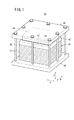
図1及び図2に示すように、本発明の第1の実施形態に係る燃料電池スタック10は、複数の固体酸化物形燃料電池12を矢印C方向(鉛直方向)に積層して構成される。この燃料電池スタック10は、定置用の他、車載用等の種々の用途に用いられている。固体酸化物形燃料電池12は、燃料ガス(水素含有ガス、例えば、水素ガスにメタン、一酸化炭素が混合した気体)と酸化剤ガス(空気)との電気化学反応により発電する。
As shown in FIGS. 1 and 2, the
固体酸化物形燃料電池12は、図3に示すように、例えば、安定化ジルコニア等の酸化物イオン導電体で構成される電解質(電解質板)14の両面に、カソード電極16及びアノード電極18が設けられた電解質・電極接合体(MEA)20を備える。カソード電極16は、アノード電極18及び電解質14よりも小さな表面積に設定されるとともに、前記カソード電極16には、集電体19が積層される。集電体19は、カソード電極16と略同一の寸法に設定され、例えば、ニッケル等の金属からなる発泡金属や金属メッシュ等により構成される。
As shown in FIG. 3, the solid
電解質・電極接合体20は、矩形状(長方形状又は正方形状)に形成されるとともに、少なくとも外周端面部には、酸化剤ガス及び燃料ガスの進入や排出を阻止するためにバリアー層(図示せず)が設けられている。
The electrolyte /
固体酸化物形燃料電池12は、一対のセパレータ(インターコネクタ)22間に、シール部材24a、24b及び金属プレート25を介装して単一の電解質・電極接合体20を挟んで構成される。セパレータ22は、例えば、ステンレス合金等の板金で構成される一方、シール部材24a、24bは、例えば、マイカ材やセラミック材等の地殻成分系素材、ガラス系素材、粘土とプラスチックの複合素材で形成される。金属プレート25は、フレーム形状を有し、内部に形成される開口部25aは、カソード電極16よりも大きく且つ電解質14よりも小さく構成される。金属プレート25は、開口部25aの周壁部が、電解質14の周縁部に積層されることにより、カソード側とアノード側との間におけるガスシール機能を有する。
The solid
セパレータ22は、長方形状(又は正方形状)を有しており、長辺方向(矢印A方向)一端側には、複数、例えば、3つの酸化剤ガス供給連通孔26aが短辺方向(矢印B方向)に配列して形成される。セパレータ22の長辺方向他端側には、矢印B方向に配列して、例えば、3つの酸化剤ガス排出連通孔26bが形成される。
The
セパレータ22の短辺方向(矢印B方向)一端側には、例えば、3つの燃料ガス供給連通孔28aが矢印A方向に配列して形成される。セパレータ22の短辺方向他端側には、例えば、3つの燃料ガス排出連通孔28bが矢印A方向に配列して形成される。
On one end side of the
セパレータ22において、電解質・電極接合体20のカソード電極16に対向する面22aに、前記カソード電極16の電極面に沿って酸化剤ガスを供給するための酸化剤ガス通路30が形成される。酸化剤ガス通路30は、矢印A方向に延在する複数本の流路溝により構成されるとともに、両端が酸化剤ガス供給連通孔26a及び酸化剤ガス排出連通孔26bの近傍で終端する。
In the
セパレータ22において、電解質・電極接合体20を構成するアノード電極18に対向する面22bには、前記アノード電極18の電極面に沿って燃料ガスを供給するための燃料ガス通路32が形成される。
In the
燃料ガス通路32は、矢印B方向に延在する複数の流路溝により構成されるとともに、両端が、燃料ガス供給連通孔28a及び燃料ガス排出連通孔28bに連通する。
The
シール部材24a、24bには、酸化剤ガス供給連通孔26a、酸化剤ガス排出連通孔26b、燃料ガス供給連通孔28a及び燃料ガス排出連通孔28bが形成される。シール部材24aには、各酸化剤ガス供給連通孔26aと酸化剤ガス通路30とを連通するための入口連結路34aと、各酸化剤ガス排出連通孔26bと前記酸化剤ガス通路30とを連通する出口連結路34bとが形成される。
An oxidant gas
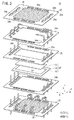
図1及び図2に示すように、複数の固体酸化物形燃料電池12は、矢印C方向に積層されることにより、積層体36が構成される。積層体36は、前記積層体36の積層方向下端(一端)に配置される下部エンドプレート(基台部)38上に載置される。
As shown in FIGS. 1 and 2, the plurality of solid
下部エンドプレート38は、矢印A方向及び矢印B方向の寸法が、積層体36の各寸法よりも大きな寸法に設定されるとともに、酸化剤ガス供給連通孔26a、酸化剤ガス排出連通孔26b、燃料ガス供給連通孔28a及び燃料ガス排出連通孔28bが形成される(図2参照)。
The
下部エンドプレート38には、周辺部に沿って複数のねじ孔40が形成される。ねじ孔40は、例えば、下部エンドプレート38の四隅近傍及び各辺の略中央部に形成される。なお、下部エンドプレート38には、図示しないが、酸化剤ガス及び燃料ガスの供給及び排出を行うためのマニホールドが装着される。
A plurality of screw holes 40 are formed in the
積層体36の積層方向上端(他端)には、上部エンドプレート42が配置される。上部エンドプレート42の矢印A方向及び矢印B方向の寸法は、積層体36の各寸法と同寸法に設定されるとともに、前記上部エンドプレート42は、長方形状(又は正方形状)の平板で構成される。
An
上部エンドプレート42上には、燃料電池保持部44と荷重プレート(架台部)46とが積層される。荷重プレート46の周縁部に孔部48が形成され、前記孔部48にボルト50が挿入されるとともに、前記ボルト50は、下部エンドプレート38のねじ孔40にねじ込まれる。
On the
燃料電池保持部44は、アルミナ層52と複合層54とを備える。アルミナ層52は、積層体36側、すなわち、上部エンドプレート42に隣接して配置される一方、複合層54は、荷重プレート46に隣接して配置される。
The fuel
アルミナ層52は、アルミナ繊維により構成される。このアルミナ層52は、具体的には、結晶質アルミナ繊維に有機バインダーを含浸させて厚さ方向に圧縮し、前記有機バインダーの溶媒部を乾燥により除去することにより形成される。アルミナ層52は、アルミナ繊維により弾性を有するとともに、高温における耐久性に優れ、しかも断熱性及び絶縁性を有している。
The
複合層54は、アルミナ繊維とバーミキュライトとの複合材を有する。この複合層54は、具体的には、バーミキュライトの粒子を、結晶質アルミナ繊維を含むスラリー中に分散させるとともに、上記のアルミナ層と同様に製造される。
The
電解質・電極接合体20は、ボルト50に比べて比較的熱膨張率の小さな材料が使用される。このため、高温時にボルト50が軸方向に伸びても、アルミナ層52自体の弾性によって積層体36の締め付け荷重が低下することを抑制する機能を有する。
The electrolyte /
さらに、バーミキュライトは、高温で比較的大きく膨張する性質を有している。このバーミキュライトの膨張率は、ボルト50の膨張率よりも大きいため、高温時における積層体36の締め付け荷重の低下を一層確実に抑制する機能を有する。
Furthermore, vermiculite has the property of expanding relatively large at high temperatures. Since the expansion coefficient of this vermiculite is larger than the expansion coefficient of the
燃料電池スタック10を組み立てる際には、下部エンドプレート38上に積層体36が載置された後、この積層体36上には、上部エンドプレート42が配置される。上部エンドプレート42上には、アルミナ層52及び複合層54が、それぞれ所定の厚さずつ載置された後、荷重プレート46が配置される。
When the
次いで、複数のボルト50が、荷重プレート46の各孔部48に挿入され、先端部が、下部エンドプレート38の各ねじ孔40にねじ込まれる。このため、積層体36に積層方向の荷重が付与されるとともに、燃料電池保持部44に圧縮荷重が付与される。
Next, a plurality of
燃料電池保持部44では、アルミナ層52及び複合層54が圧縮される。そして、燃料電池保持部44により、積層体36に必要な面圧を発生させる締め付け荷重が得られた際に、ボルト50の締め付けが終了され、燃料電池スタック10の組み立て作業が完了する。
In the fuel
このように構成される燃料電池スタック10の動作について、以下に説明する。
The operation of the
図2に示すように、燃料電池スタック10を構成する下部エンドプレート38には、図示しないマニホールドを介して燃料ガス(例えば、水素ガス)と酸化剤ガスである、例えば、空気とが供給される。空気は、酸化剤ガス供給連通孔26aに沿って鉛直上方向に移動する。
As shown in FIG. 2, the
各固体酸化物形燃料電池12では、図3に示すように、シール部材24aの酸化剤ガス供給連通孔26aに連通する入口連結路34aを通って、セパレータ22の酸化剤ガス通路30に供給される。空気は、酸化剤ガス通路30を矢印A方向に移動しながら、電解質・電極接合体20のカソード電極16に供給された後、酸化剤ガス排出連通孔26bに排出される。
In each solid
一方、燃料ガスは、燃料ガス供給連通孔28aに沿って鉛直上方向に移動し、各固体酸化物形燃料電池12を構成するセパレータ22の燃料ガス通路32に供給される。燃料ガスは、燃料ガス通路32に沿って矢印B方向に移動しながら、電解質・電極接合体20のアノード電極18に供給された後、燃料ガス排出連通孔28bに排出される。
On the other hand, the fuel gas moves vertically upward along the fuel gas
従って、電解質・電極接合体20では、アノード電極18に燃料ガスが供給されるとともに、カソード電極16に空気が供給される。これにより、酸化物イオンが、電解質14を通ってアノード電極18に移動し、化学反応により発電が行われる。
Therefore, in the electrolyte /
この場合、第1の実施形態では、上部エンドプレート42と荷重プレート46との間に、燃料電池保持部44が配置されるとともに、前記燃料電池保持部44は、アルミナ層52と複合層54とを備えている。
In this case, in the first embodiment, the fuel
複合層54は、弾性を有し、高温における耐久性、断熱性及び絶縁性に優れるアルミナ繊維と、高温時の熱膨張率が大きいバーミキュライトとを有している。このため、複合層54は、耐熱性、断熱性及び熱膨張性に優れ、燃料電池スタック10の温度変化に容易に追従して、積層体36に所望の締め付け荷重を確実に付与することができる。従って、燃料電池スタック10の積層荷重が一定化され、発電性能の向上が図られる。
The
具体的には、ボルト50は、例えば、ニッケル系耐熱合金等の線膨張係数の大きな材料で構成されており、電解質・電極接合体20に比べて熱膨張が相当に大きい。従って、高温時には、積層体36の積層方向の伸びに対してボルト50の伸びが大きくなり、前記積層体36に付与される締め付け荷重が低下し易くなる。
Specifically, the
その際、バーミキュライトは、高温時の熱膨張がボルト50の軸方向の伸びよりも大きい。これにより、積層体36の締め付け荷重が低下をすることを、良好に抑制することが可能になる。
At that time, vermiculite has a thermal expansion at a high temperature larger than the axial extension of the
さらに、第1の実施形態では、アルミナ層52が、上部エンドプレート42に隣接して配置される一方、複合層54が、荷重プレート46に隣接して配置されている。アルミナ層52は、アルミナ繊維により構成されており、このアルミナ繊維は、弾性を有するとともに、高温における耐熱性に優れている。その上、アルミナ繊維は、断熱性及び絶縁性を有しており、アルミナ層52は、高温で運転される積層体36の端部に良好に配置可能になる。
Further, in the first embodiment, the
しかも、アルミナ層52は、断熱性を有するため、複合層54は、バーミキュライトが積層体36からの温度に直接曝されることがない。さらに、複合層54は、バーミキュライトが熱膨張することにより、燃料電池スタック10の温度変化に容易に追従し、積層体36に所望の締め付け荷重を確実に付与することができるという効果が得られる。
Moreover, since the
一方、アルミナ層52は、ヤング率が相当に小さく、締め付け代を大きく取ることが可能になる。このため、積層体36の温度による寸法変化を十分に吸収することができる。
On the other hand, the
アルミナ繊維は、常温から高温まで弾性を保持することが可能である。従って、燃料電池スタック10の組み立て時から、定常運転及び負荷変動運転時等の全ての温度域において、前記燃料電池スタック10の締め付け荷重を保持させることができる。
Alumina fibers can retain elasticity from room temperature to high temperatures. Therefore, the tightening load of the
しかも、アルミナ繊維は、断熱性が高いため、上部エンドプレート42に隣接して配置されることにより、燃料電池スタック10の断熱性が向上する。これにより、燃料電池スタック10からの放熱を良好に抑制するとともに、熱自立が促進され、スタック効率の向上が容易に図られるという利点が得られる。
In addition, since the alumina fibers have high heat insulating properties, the heat insulating properties of the
さらにまた、燃料電池スタック10では、固体酸化物形燃料電池12が、平板積層型固体酸化物形燃料電池である。このため、特に、平板型固体酸化物形燃料電池のような高温型燃料電池を有効に用いることができる。
Furthermore, in the
図5は、本発明の第2の実施形態に係る燃料電池スタック60の概略斜視説明図である。
FIG. 5 is a schematic perspective explanatory view of a
なお、第1の実施形態に係る燃料電池スタック10と同一の構成要素には、同一の参照符号を付して、その詳細な説明は省略する。また、以下に説明する第3の実施形態においても同様に、その詳細な説明は省略する。
The same components as those of the
燃料電池スタック60では、図4及び図5に示すように、第1の実施形態の荷重プレート46に変えてボックス62を備える。ボックス62は、例えば、フェライト系ステンレスで構成されており、開口側端部には、外方に突出するフランジ部64が設けられフランジ部64には、複数の孔部66が形成される。
As shown in FIGS. 4 and 5, the
下部エンドプレート38上には、シール部材68を介して載置される。シール部材68は、額縁状を有するとともに、複数の孔部70が、孔部66と同軸上に形成される。
It is placed on the
孔部66、70には、ボルト72が一体に挿入され、このボルト72が、下部エンドプレート38のねじ孔40にねじ込まれることにより、ボックス62の底部(架台部)62aが燃料電池保持部44を積層方向に押圧する。ボックス62内には、積層体36の外方を周回して断熱材74が配置される。断熱材74は、矩形状を有し、例えば、マイカ等により構成される。
このように構成される第2の実施形態では、複合層54を構成するバーミキュライトの熱膨張率は、ボックス62の熱膨張率よりも大きい。このため、特に、高温時におけるボックス62の伸びによる積層体36の締め付け荷重の低下を良好に阻止することができる。これにより、所望の締め付け荷重を確実に付与して、燃料電池スタック60全体の発電性能の向上が容易に図られる等、上記の第1に実施形態と同様の効果が得られる。
In the second embodiment configured as described above, the thermal expansion coefficient of the vermiculite constituting the
しかも、第2の実施形態では、ボックス62は、安価で且つ線膨張係数が小さいフェライト系ステンレスで構成されており、積層体36との熱膨張差を小さくすることが可能になる。従って、高温時の荷重低下を一層低減することが可能になる。その上、耐熱合金の使用量を少なくすることができ、燃料電池スタック60を経済的に構成することが可能になる。
Moreover, in the second embodiment, the
さらにまた、ボックス62内には、積層体36の側壁に沿って断熱材74が配置されている。このため、ボックス62を気密に構成すると同時に、積層体36からの放熱を抑制して、発電効率の向上が容易に図られる。
Furthermore, a
図6は、本発明の第3の実施形態に係る燃料電池スタック80の概略斜視説明図である。
FIG. 6 is a schematic perspective explanatory view of a
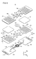
図6及び図7に示すように、燃料電池スタック80は、矢印C方向に積層される複数の固体酸化物形燃料電池82を備え、複数の前記固体酸化物形燃料電池82が積層されて積層体84が構成される。
6 and 7, the
固体酸化物形燃料電池82は、図8に示すように、同一平面状に2つの電解質・電極接合体20を挟持する一組のセパレータ86を備える。セパレータ86は、第1プレート88と第2プレート90とを備え、前記第1プレート88及び前記第2プレート90は、例えば、ステンレス合金等の板金で構成され、ろう付け、拡散接合やレーザ溶接等により互いに接合される。
As shown in FIG. 8, the solid
セパレータ86は、中央部に燃料ガス供給連通孔(反応ガス供給連通孔)92が形成される燃料ガス供給部(反応ガス供給部)94を有する。燃料ガス供給部94には、互いに反対方向に延在して一対の橋架部96A、96Bが連結されるとともに、一対の前記橋架部96A、96Bには、前記燃料ガス供給部94を中心に対称位置にそれぞれ挟持部98A、98Bが一体に設けられる。
The
第1プレート88は、燃料ガス供給連通孔92が形成される第1円板部100を有し、前記第1円板部100から互いに反対方向に延在して、第1長板部102A、102Bが一体に設けられる。第1及び第2長板部102A、102Bには、第1矩形状部104A、104Bが一体に設けられる。第1矩形状部104A、104Bの各カソード電極16に対向する面部には、複数の突起部106A、106Bを介して、それぞれ酸化剤ガス通路30A、30Bが形成される。
The first plate 88 includes a
第2プレート90は、中央に燃料ガス供給連通孔92が形成される第2円板部108を有し、前記第2円板部108には、互いに逆方向に延在して第2長板部110A、110Bが一体に設けられる。第2長板部110A、110Bには、それぞれ第2矩形状部112A、112Bが一体に設けられる。
The
各第2長板部110A、110Bから各第2矩形状部112A、112Bの途上に延在して、燃料ガス供給通路114A、114Bが形成されるとともに、前記燃料ガス供給通路114A、114Bの終端縁部には、燃料ガス供給孔116A、116Bが形成される。第2矩形状部112A、112Bには、燃料ガス供給通路114A、114Bが形成される面側に、それぞれ複数の燃料ガス排出孔117A、117Bが形成される。
Fuel
図9に示すように、第2矩形状部112A、112Bのアノード電極18に接触する面側には、複数の突起部118A、118Bを介して燃料ガス通路32A、32Bが形成される。燃料ガス通路32A、32Bは、外縁周回用凸部120A、120Bにより周回されるとともに、それぞれ燃料ガス排出孔117A、117Bに連通する貫通孔122A、122Bが形成される。燃料ガス供給孔116A、116Bと燃料ガス排出孔117A、117Bとの間には、V字状の迂回路形成用壁部124A、124Bが形成される。
As shown in FIG. 9,
図8に示すように、橋架部96A、96Bの両側には、酸化剤ガスを矢印C方向に流通させるための酸化剤ガス供給連通孔126が設けられる。酸化剤ガス供給連通孔126は、例えば、鉛直上方向に酸化剤ガスを流通させるとともに、各固体酸化物形燃料電池82を構成する酸化剤ガス通路30A、30Bに沿って、前記酸化剤ガスを矢印A方向に供給する。
As shown in FIG. 8, an oxidant gas
電解質・電極接合体20を挟んで配設される一対のセパレータ86において、各燃料ガス供給部94間には、燃料ガス供給連通孔92をシールするための絶縁シール128が設けられる。絶縁シール128は、例えば、マイカ材やセラミック材等の地殻成分系素材、ガラス系素材、粘土とプラスチックの複合素材で形成される。
In the pair of
各固体酸化物形燃料電池82には、挟持部98A、98Bの矢印A方向外方に位置して、排ガス排出連通孔130が形成される。この排ガス排出連通孔130は、電解質・電極接合体20に供給されて反応に使用された燃料ガス及び酸化剤ガスを排ガスとして積層方向に排出する。
Each solid
燃料電池スタック80は、図6及び図7に示すように、積層体84の積層方向下端(一端)に配置される下部エンドプレート132と、前記積層体84の積層方向上端(他端)に各挟持部98A、98Bに対応して配置される上部エンドプレート134A、134Bと、燃料ガス供給部94に対応して配置される燃料シールプレート136とを備える。
As shown in FIGS. 6 and 7, the
燃料シールプレート136には、第1燃料電池保持部138が配置されるとともに、上部エンドプレート134A、134B上には、第2燃料電池保持部140A、140Bが配置され、これらにより燃料電池保持部が構成される。
A first fuel
第1燃料電池保持部138は、燃料シールプレート136に隣接するアルミナ層142と、このアルミナ層142上に積層される複合層144とを有する。アルミナ層142及び複合層144は、燃料シールプレート136に対応して円板状に構成される。
The first fuel
第2燃料電池保持部140A、140Bは、上部エンドプレート134A、134B上に載置されるアルミナ層52A、52Bと、前記アルミナ層52A、52B上に積層される複合層54A、54Bとを備える。
The second fuel
アルミナ層142、52A及び52Bは、上記のアルミナ層52と同一に構成され、複合層144、54A及び54Bは、上記の複合層54と同様に構成される。
The alumina layers 142, 52A and 52B are configured the same as the
第1燃料電池保持部138は、第2燃料電池保持部140A、140Bよりも積層方向(矢印C方向)に大きな荷重を付与するように、例えば、アルミナ繊維の圧縮量を大きくとり、あるいは、密度を大きく設定する等により構成される。
The first fuel
燃料電池スタック80は、ボックス146を備える。このボックス146の開口部側端部にフランジ部148が形成されるとともに、このフランジ部148と下部エンドプレート132との間には、シール部材150が介装される。フランジ部148と下部エンドプレート132とは、複数本のボルト72を介して固定される。
The
下部エンドプレート132には、図10に示すように、酸化剤ガス供給連通孔126に連通するそれぞれ2つの空気用孔部152a、152bと、排ガス排出連通孔130に連通する2つの排ガス用孔部154a、154bとが形成される。下部エンドプレート132には、燃料ガス供給連通孔92に連通するひとつの燃料ガス用孔部155が形成される。
As shown in FIG. 10, the
図6、図7及び図10に示すように、積層体84とボックス146内との間には、挟持部98A、98Bの三面を囲ってそれぞれ3つの断熱部材156A、156Bが配置される。断熱部材156A、156Bは、例えば、マイカ等の断熱材で構成される。
As shown in FIGS. 6, 7, and 10, three heat insulating members 156 </ b> A and 156 </ b> B are disposed between the
このように構成される燃料電池スタック80の動作について、以下に説明する。
The operation of the
燃料ガスは、下部エンドプレート132の燃料ガス用孔部155から燃料電池スタック80の燃料ガス供給連通孔92に供給される。一方、空気は、下部エンドプレート132の空気用孔部152a、152bから燃料電池スタック80の酸化剤ガス供給連通孔126に供給される。
The fuel gas is supplied from the
図8に示すように、燃料ガス供給連通孔92に供給された燃料ガスは、各固体酸化物形燃料電池82を構成するセパレータ86において、橋架部96A、96Bに形成されている燃料ガス供給通路114A、114Bに導入される。燃料ガスは、燃料ガス供給通路114A、114Bから燃料ガス供給孔116A、116Bを通って燃料ガス通路32A、32Bに導入される。
As shown in FIG. 8, the fuel gas supplied to the fuel gas
図9に示すように、燃料ガス通路32A、32Bに導入された燃料ガスは、迂回路形成用壁部124A、124Bの案内作用下に、前記燃料ガス通路32A、32Bを通って電解質・電極接合体20のアノード電極18に供給された後、各燃料ガス排出孔117A、117Bを通って排ガス排出連通孔130に排出される。
As shown in FIG. 9, the fuel gas introduced into the
一方、酸化剤ガス供給連通孔126に供給された空気は、各電解質・電極接合体20のカソード電極16とセパレータ86との間に形成されている酸化剤ガス通路30A、30Bに導入される。酸化剤ガスは、酸化剤ガス通路30A、30Bを矢印A方向に移動しながら、電解質・電極接合体20のカソード電極16に供給された後、排ガス排出連通孔130に排出される。
On the other hand, the air supplied to the oxidant gas
この場合、第3の実施形態では、燃料ガス供給部94に積層方向に荷重を付与する第1燃料電池保持部138と、挟持部98A、98Bに電解質・電極接合体20に対応して、前記積層方向に荷重を付与する第2燃料電池保持部140A、140Bとを有している。
In this case, in the third embodiment, the first fuel
そして、第1燃料電池保持部138は、第2燃料電池保持部140A、140Bよりも積層方向に大きな荷重を付与している。これにより、燃料ガス供給部94には、比較的大きな荷重が付与されるため、前記燃料ガス供給部94のシール性を良好に維持することが可能になる。
The first fuel
一方、電解質・電極接合体20には、挟持部98A、98Bとの密着性を高める程度の比較的小さな荷重を付与することができる。従って、電解質・電極接合体20の損傷を可及的に阻止するとともに、効率的な発電及び集電が遂行されるという効果が得られる。
On the other hand, the electrolyte /
さらに、第3の実施形態では、上記の第1及び第2の実施形態と同様の効果が得られる。 Furthermore, in the third embodiment, the same effect as in the first and second embodiments can be obtained.
10、60、80…燃料電池スタック
12、82…固体酸化物形燃料電池
14…電解質
16…カソード電極 18…アノード電極
20…電解質・電極接合体 22、86…セパレータ
24a、24b…シール部材
26a、126…酸化剤ガス供給連通孔 26b…酸化剤ガス排出連通孔
28a、92…燃料ガス供給連通孔 28b…燃料ガス排出連通孔
30、30A、30B…酸化剤ガス通路
32、32A、32B…燃料ガス通路 36、84…積層体
38、132…下部エンドプレート
42、134A、134B…上部エンドプレート
44、138、140A、140B…燃料電池保持部
46…荷重プレート 50、72…ボルト
52、52A、142…アルミナ層 54、54A、144…複合層
62、146…ボックス 62a…底部
64、148…フランジ部 68、150…シール部材
74…断熱材 92…燃料ガス供給連通孔
94…燃料ガス供給部 96A、96B…橋架部
98A、98B…挟持部
10, 60, 80 ...
Claims (6)
前記積層体の積層方向一端に配置される基台部と、
前記積層体の積層方向他端に配置され、該積層体に積層方向に沿って荷重を付与する架台部と、
前記架台部と前記積層体との間に配置され、アルミナ繊維とバーミキュライトとの複合材を有する燃料電池保持部と、
を備えることを特徴とする燃料電池スタック。 A laminate in which an electrolyte / electrode assembly configured by sandwiching an electrolyte between an anode electrode and a cathode electrode includes a solid oxide fuel cell laminated between separators, and a plurality of the solid oxide fuel cells are laminated. A fuel cell stack having a body,
A base portion disposed at one end in the stacking direction of the stacked body;
A gantry part that is disposed at the other end in the stacking direction of the stack, and applies a load along the stacking direction to the stack,
A fuel cell holding part disposed between the gantry part and the laminate, and having a composite material of alumina fiber and vermiculite;
A fuel cell stack comprising:
前記複合材により構成される複合層と、
を備えるとともに、
前記アルミナ層は、前記積層体側に配置され且つ前記複合層は、前記架台部側に配置されることを特徴とする燃料電池スタック。 The fuel cell stack according to claim 1, wherein the fuel cell holding part includes an alumina layer composed of alumina fibers,
A composite layer composed of the composite material;
With
The fuel cell stack, wherein the alumina layer is disposed on the stacked body side, and the composite layer is disposed on the gantry side.
前記プレート部材と前記基台部とは、複数のボルトを介して前記積層方向に締め付け保持されることを特徴とする燃料電池スタック。 The fuel cell stack according to claim 1 or 2, wherein the gantry part is a plate member arranged in parallel with the base part,
The fuel cell stack, wherein the plate member and the base portion are clamped and held in the stacking direction via a plurality of bolts.
前記ボックスの開口側端部は、前記基台部に隣接して複数のボルトを介し前記積層方向に締め付け保持されることを特徴とする燃料電池スタック。 3. The fuel cell stack according to claim 1, wherein the gantry is configured by a bottom of a box that houses the stacked body,
An opening side end portion of the box is clamped and held in the stacking direction via a plurality of bolts adjacent to the base portion.
前記挟持部に連結され、前記燃料ガスを前記燃料ガス通路に又は前記酸化剤ガスを前記酸化剤ガス通路に供給するための反応ガス供給通路が形成される橋架部と、
前記橋架部に連結され、前記燃料ガス又は前記酸化剤ガスを前記反応ガス供給通路に供給するための反応ガス供給連通孔が積層方向に形成される反応ガス供給部と、
を備え、
前記燃料電池保持部は、前記反応ガス供給部に前記積層方向に荷重を付与する第1燃料電池保持部と、
前記挟持部に前記電解質・電極接合体に対応して前記積層方向に荷重を付与する第2燃料電池保持部と、
を有し、
前記第1燃料電池保持部は、前記第2燃料電池保持部よりも前記積層方向に大きな荷重を付与することを特徴とする燃料電池スタック。 5. The fuel cell stack according to claim 2, wherein the separator sandwiches the electrolyte-electrode assembly and supplies fuel gas along the electrode surface of the anode electrode. 6. And a sandwiching portion in which an oxidant gas passage for supplying an oxidant gas along the electrode surface of the cathode electrode is individually provided;
A bridge portion connected to the sandwiching portion and formed with a reaction gas supply passage for supplying the fuel gas to the fuel gas passage or the oxidant gas to the oxidant gas passage;
A reaction gas supply unit that is connected to the bridge part and has a reaction gas supply communication hole formed in the stacking direction for supplying the fuel gas or the oxidant gas to the reaction gas supply passage;
With
The fuel cell holding unit includes a first fuel cell holding unit that applies a load to the reaction gas supply unit in the stacking direction;
A second fuel cell holding part for applying a load in the stacking direction to the sandwiching part corresponding to the electrolyte / electrode assembly;
Have
The fuel cell stack, wherein the first fuel cell holding part applies a larger load in the stacking direction than the second fuel cell holding part.
Priority Applications (4)
| Application Number | Priority Date | Filing Date | Title |
|---|---|---|---|
| JP2010267952A JP5437222B2 (en) | 2010-12-01 | 2010-12-01 | Fuel cell stack |
| US13/824,245 US9054350B2 (en) | 2010-12-01 | 2011-10-26 | Fuel cell stack |
| PCT/JP2011/075232 WO2012073640A1 (en) | 2010-12-01 | 2011-10-26 | Fuel cell stack |
| EP11785799.5A EP2647076B1 (en) | 2010-12-01 | 2011-10-26 | Fuel cell stack |
Applications Claiming Priority (1)
| Application Number | Priority Date | Filing Date | Title |
|---|---|---|---|
| JP2010267952A JP5437222B2 (en) | 2010-12-01 | 2010-12-01 | Fuel cell stack |
Publications (2)
| Publication Number | Publication Date |
|---|---|
| JP2012119164A JP2012119164A (en) | 2012-06-21 |
| JP5437222B2 true JP5437222B2 (en) | 2014-03-12 |
Family
ID=45003018
Family Applications (1)
| Application Number | Title | Priority Date | Filing Date |
|---|---|---|---|
| JP2010267952A Expired - Fee Related JP5437222B2 (en) | 2010-12-01 | 2010-12-01 | Fuel cell stack |
Country Status (4)
| Country | Link |
|---|---|
| US (1) | US9054350B2 (en) |
| EP (1) | EP2647076B1 (en) |
| JP (1) | JP5437222B2 (en) |
| WO (1) | WO2012073640A1 (en) |
Families Citing this family (14)
| Publication number | Priority date | Publication date | Assignee | Title |
|---|---|---|---|---|
| JP5684665B2 (en) * | 2011-07-13 | 2015-03-18 | 本田技研工業株式会社 | Fuel cell stack |
| JP5684664B2 (en) * | 2011-07-13 | 2015-03-18 | 本田技研工業株式会社 | Fuel cell stack |
| US10075471B2 (en) | 2012-06-07 | 2018-09-11 | Amazon Technologies, Inc. | Data loss prevention techniques |
| CN105051959B (en) * | 2013-01-21 | 2017-07-07 | 福莱西投资公司 | For the pad of fuel cell |
| JP6175410B2 (en) * | 2013-06-28 | 2017-08-02 | 日本特殊陶業株式会社 | Fuel cell and manufacturing method thereof |
| JP6054912B2 (en) * | 2013-06-28 | 2016-12-27 | 日本特殊陶業株式会社 | Fuel cell and manufacturing method thereof |
| JP6290676B2 (en) * | 2014-03-25 | 2018-03-07 | 東京瓦斯株式会社 | Fuel cell |
| JP6628224B2 (en) * | 2015-12-07 | 2020-01-08 | パナソニックIpマネジメント株式会社 | High temperature operation fuel cell |
| FR3045215B1 (en) * | 2015-12-15 | 2023-03-03 | Commissariat Energie Atomique | AUTONOMOUS CLAMPING SYSTEM FOR A SOEC/SOFC TYPE SOLID OXIDE STACK AT HIGH TEMPERATURE |
| CA3062176C (en) | 2017-05-04 | 2024-01-23 | Versa Power Systems Ltd. | Compact high temperature electrochemical cell stack architecture |
| JP6596039B2 (en) * | 2017-05-25 | 2019-10-23 | 本田技研工業株式会社 | Fuel cell stack |
| JP7140590B2 (en) * | 2018-07-24 | 2022-09-21 | 株式会社東芝 | electrochemical cell stack |
| US20220328857A1 (en) * | 2019-10-04 | 2022-10-13 | Redflow R&D Pty Ltd | Welded flowing electrolyte battery cell stack |
| GB201917650D0 (en) | 2019-12-03 | 2020-01-15 | Ceres Ip Co Ltd | Cell unit and cell stack |
Family Cites Families (10)
| Publication number | Priority date | Publication date | Assignee | Title |
|---|---|---|---|---|
| JPH0636783A (en) * | 1992-07-17 | 1994-02-10 | Mitsubishi Heavy Ind Ltd | Fuel electrode current collector for flat type solid electrolyte fuel cell |
| JPH09139223A (en) | 1995-11-14 | 1997-05-27 | Tokyo Gas Co Ltd | Lamination compressing device for flat solid electrolytic fuel cell |
| JP4291299B2 (en) | 2005-06-02 | 2009-07-08 | 日本電信電話株式会社 | Flat type solid oxide fuel cell |
| NO20053220D0 (en) | 2005-06-29 | 2005-06-29 | Norsk Hydro As | Compression of a PEM cell stack in a pressure tank. |
| JP4892897B2 (en) | 2005-09-07 | 2012-03-07 | 三菱マテリアル株式会社 | Fuel cell |
| DE102006060809A1 (en) * | 2006-12-21 | 2008-06-26 | Enerday Gmbh | Insulating and bracing device for a high temperature fuel cell system component |
| US7858259B2 (en) * | 2007-01-26 | 2010-12-28 | Topsoe Fuel Cell A/S | Fuel cell stack clamping structure and solid oxide fuel cell stack |
| AU2008209059B2 (en) * | 2007-01-26 | 2011-11-24 | Haldor Topsoe A/S | Fuel cell stack clamping structure and solid oxide fuel cell stack |
| JP5383051B2 (en) * | 2008-01-21 | 2014-01-08 | 本田技研工業株式会社 | Fuel cell and fuel cell stack |
| JP5449411B2 (en) * | 2009-03-13 | 2014-03-19 | トプサー・フューエル・セル・アクチエゼルスカベット | COMPRESSION CASING FOR FUEL CELL STACK AND METHOD FOR PRODUCING COMPRESSION CASING FOR FUEL CELL STACK |
-
2010
- 2010-12-01 JP JP2010267952A patent/JP5437222B2/en not_active Expired - Fee Related
-
2011
- 2011-10-26 WO PCT/JP2011/075232 patent/WO2012073640A1/en active Application Filing
- 2011-10-26 EP EP11785799.5A patent/EP2647076B1/en not_active Not-in-force
- 2011-10-26 US US13/824,245 patent/US9054350B2/en active Active
Also Published As
| Publication number | Publication date |
|---|---|
| JP2012119164A (en) | 2012-06-21 |
| EP2647076B1 (en) | 2014-12-10 |
| WO2012073640A1 (en) | 2012-06-07 |
| EP2647076A1 (en) | 2013-10-09 |
| US9054350B2 (en) | 2015-06-09 |
| US20130177829A1 (en) | 2013-07-11 |
Similar Documents
| Publication | Publication Date | Title |
|---|---|---|
| JP5437222B2 (en) | Fuel cell stack | |
| JP5684664B2 (en) | Fuel cell stack | |
| JP5684665B2 (en) | Fuel cell stack | |
| JP6216283B2 (en) | Fuel cell stack | |
| JP5383051B2 (en) | Fuel cell and fuel cell stack | |
| JP2000331692A (en) | Plate type cell with retaining thin plate frame and fuel cell using same | |
| WO2006077762A1 (en) | Flat laminate type fuel cell and fuel cell stack | |
| JP5127389B2 (en) | Fuel cell and fuel cell stack | |
| KR100413397B1 (en) | Polymer electrolyte fuel cell and its usage | |
| JP5881594B2 (en) | Fuel cell stack and manufacturing method thereof | |
| WO2018154656A1 (en) | Flat plate type electrochemical cell stack | |
| JP6294134B2 (en) | Fuel cell stack | |
| JP4461949B2 (en) | Solid oxide fuel cell | |
| JP5756653B2 (en) | Fuel cell stack | |
| JP6389959B2 (en) | Fuel cell stack and fuel cell stack manufacturing method | |
| JP2020170631A (en) | Electrochemical reaction cell stack | |
| JP4083416B2 (en) | Fuel cell stack | |
| JP2012129134A (en) | Flat plate type solid oxide fuel cell stack | |
| JP5366626B2 (en) | Fuel cell module | |
| JP4664020B2 (en) | Manufacturing method of fuel cell stack | |
| JP2022066744A (en) | Electrochemical reaction cell stack | |
| JP2012182031A (en) | Fuel cell stack | |
| JP2017010721A (en) | Fuel cell stack | |
| JP2014026956A (en) | Solid oxide fuel cell | |
| JP2007134163A (en) | Polymer electrolyte fuel cell |
Legal Events
| Date | Code | Title | Description |
|---|---|---|---|
| A621 | Written request for application examination |
Free format text: JAPANESE INTERMEDIATE CODE: A621 Effective date: 20121127 |
|
| TRDD | Decision of grant or rejection written | ||
| A01 | Written decision to grant a patent or to grant a registration (utility model) |
Free format text: JAPANESE INTERMEDIATE CODE: A01 Effective date: 20131112 |
|
| A61 | First payment of annual fees (during grant procedure) |
Free format text: JAPANESE INTERMEDIATE CODE: A61 Effective date: 20131211 |
|
| R150 | Certificate of patent or registration of utility model |
Ref document number: 5437222 Country of ref document: JP Free format text: JAPANESE INTERMEDIATE CODE: R150 Free format text: JAPANESE INTERMEDIATE CODE: R150 |
|
| R250 | Receipt of annual fees |
Free format text: JAPANESE INTERMEDIATE CODE: R250 |
|
| LAPS | Cancellation because of no payment of annual fees |