EP2647076B1 - Fuel cell stack - Google Patents
Fuel cell stack Download PDFInfo
- Publication number
- EP2647076B1 EP2647076B1 EP11785799.5A EP11785799A EP2647076B1 EP 2647076 B1 EP2647076 B1 EP 2647076B1 EP 11785799 A EP11785799 A EP 11785799A EP 2647076 B1 EP2647076 B1 EP 2647076B1
- Authority
- EP
- European Patent Office
- Prior art keywords
- fuel cell
- fuel
- stack
- oxygen
- cell stack
- Prior art date
- Legal status (The legal status is an assumption and is not a legal conclusion. Google has not performed a legal analysis and makes no representation as to the accuracy of the status listed.)
- Not-in-force
Links
Images


Classifications
-
- H—ELECTRICITY
- H01—ELECTRIC ELEMENTS
- H01M—PROCESSES OR MEANS, e.g. BATTERIES, FOR THE DIRECT CONVERSION OF CHEMICAL ENERGY INTO ELECTRICAL ENERGY
- H01M8/00—Fuel cells; Manufacture thereof
- H01M8/02—Details
- H01M8/0271—Sealing or supporting means around electrodes, matrices or membranes
- H01M8/0273—Sealing or supporting means around electrodes, matrices or membranes with sealing or supporting means in the form of a frame
-
- H—ELECTRICITY
- H01—ELECTRIC ELEMENTS
- H01M—PROCESSES OR MEANS, e.g. BATTERIES, FOR THE DIRECT CONVERSION OF CHEMICAL ENERGY INTO ELECTRICAL ENERGY
- H01M8/00—Fuel cells; Manufacture thereof
- H01M8/02—Details
- H01M8/0271—Sealing or supporting means around electrodes, matrices or membranes
- H01M8/028—Sealing means characterised by their material
- H01M8/0282—Inorganic material
-
- H—ELECTRICITY
- H01—ELECTRIC ELEMENTS
- H01M—PROCESSES OR MEANS, e.g. BATTERIES, FOR THE DIRECT CONVERSION OF CHEMICAL ENERGY INTO ELECTRICAL ENERGY
- H01M8/00—Fuel cells; Manufacture thereof
- H01M8/10—Fuel cells with solid electrolytes
- H01M8/12—Fuel cells with solid electrolytes operating at high temperature, e.g. with stabilised ZrO2 electrolyte
- H01M8/1213—Fuel cells with solid electrolytes operating at high temperature, e.g. with stabilised ZrO2 electrolyte characterised by the electrode/electrolyte combination or the supporting material
- H01M8/1226—Fuel cells with solid electrolytes operating at high temperature, e.g. with stabilised ZrO2 electrolyte characterised by the electrode/electrolyte combination or the supporting material characterised by the supporting layer
-
- H—ELECTRICITY
- H01—ELECTRIC ELEMENTS
- H01M—PROCESSES OR MEANS, e.g. BATTERIES, FOR THE DIRECT CONVERSION OF CHEMICAL ENERGY INTO ELECTRICAL ENERGY
- H01M8/00—Fuel cells; Manufacture thereof
- H01M8/24—Grouping of fuel cells, e.g. stacking of fuel cells
- H01M8/2465—Details of groupings of fuel cells
- H01M8/247—Arrangements for tightening a stack, for accommodation of a stack in a tank or for assembling different tanks
-
- H—ELECTRICITY
- H01—ELECTRIC ELEMENTS
- H01M—PROCESSES OR MEANS, e.g. BATTERIES, FOR THE DIRECT CONVERSION OF CHEMICAL ENERGY INTO ELECTRICAL ENERGY
- H01M8/00—Fuel cells; Manufacture thereof
- H01M8/24—Grouping of fuel cells, e.g. stacking of fuel cells
- H01M8/2465—Details of groupings of fuel cells
- H01M8/2483—Details of groupings of fuel cells characterised by internal manifolds
-
- H—ELECTRICITY
- H01—ELECTRIC ELEMENTS
- H01M—PROCESSES OR MEANS, e.g. BATTERIES, FOR THE DIRECT CONVERSION OF CHEMICAL ENERGY INTO ELECTRICAL ENERGY
- H01M8/00—Fuel cells; Manufacture thereof
- H01M8/10—Fuel cells with solid electrolytes
-
- H—ELECTRICITY
- H01—ELECTRIC ELEMENTS
- H01M—PROCESSES OR MEANS, e.g. BATTERIES, FOR THE DIRECT CONVERSION OF CHEMICAL ENERGY INTO ELECTRICAL ENERGY
- H01M8/00—Fuel cells; Manufacture thereof
- H01M8/24—Grouping of fuel cells, e.g. stacking of fuel cells
- H01M8/2465—Details of groupings of fuel cells
- H01M8/247—Arrangements for tightening a stack, for accommodation of a stack in a tank or for assembling different tanks
- H01M8/2475—Enclosures, casings or containers of fuel cell stacks
-
- Y—GENERAL TAGGING OF NEW TECHNOLOGICAL DEVELOPMENTS; GENERAL TAGGING OF CROSS-SECTIONAL TECHNOLOGIES SPANNING OVER SEVERAL SECTIONS OF THE IPC; TECHNICAL SUBJECTS COVERED BY FORMER USPC CROSS-REFERENCE ART COLLECTIONS [XRACs] AND DIGESTS
- Y02—TECHNOLOGIES OR APPLICATIONS FOR MITIGATION OR ADAPTATION AGAINST CLIMATE CHANGE
- Y02E—REDUCTION OF GREENHOUSE GAS [GHG] EMISSIONS, RELATED TO ENERGY GENERATION, TRANSMISSION OR DISTRIBUTION
- Y02E60/00—Enabling technologies; Technologies with a potential or indirect contribution to GHG emissions mitigation
- Y02E60/30—Hydrogen technology
- Y02E60/50—Fuel cells
Definitions
- the present invention relates to a fuel cell stack including a stack body formed by stacking a plurality of solid oxide fuel cells. Each of the solid oxide fuel cells is formed by stacking an electrolyte electrode assembly between separators.
- the electrolyte electrode assembly includes an anode, a cathode, and an electrolyte interposed between the anode and the cathode.
- SOFC solid oxide fuel cells
- electrolyte of ion-conductive oxide such as stabilized zirconia
- MEA electrolyte electrode assembly
- the electrolyte electrode assembly is interposed between a pair of separators (bipolar plates).
- separators bipolar plates
- a predetermined numbers of the separators and the electrolyte electrode assemblies are stacked together to form a fuel cell stack.
- the fuel cells need to be stacked together under the desired pressure. Further, in order to prevent leakage of the reactant gas such as the fuel gas and the air as much as possible, reactant gas manifolds need to be sealed reliably by applying pressure to the reactant gas manifolds in the stacking direction.
- a flat plate type solid oxide fuel cell disclosed in Japanese Laid-Open Patent Publication No. 2006-339035 includes a cell stack 1a and four manifolds M1 to M4 provided around the cell stack 1a.
- a fuel gas and an oxygen-containing gas are supplied to, and discharged from each of unit cells 2a through the manifolds M1 to M4.
- a first pressure applying mechanism 3a applies pressure to the cell stack 1a, and a second pressure applying mechanism 4a applies pressure to the manifolds M1 to M4.
- the first pressure applying mechanism 3a includes a compression spring 5a as pressure applying means, and the second pressure applying mechanism 4a includes a compression spring 6a as pressure applying means.
- FIG. 12 a large number of units 3b each formed by sandwiching a power generation cell 1b between a pair of separators 2b are stacked together. At both ends (upper and lower ends) in the stacking direction of the fuel cell, an upper tightening plate 4b and a lower tightening plate 5b are provided. A large circular hole 6b is formed at the center of the upper tightening plate 4b. The circular hole 6b is larger than the outer shape of the power generation cell 1b, and a weight 7b is placed in the circular hole 6b.
- the upper tightening plate 4b and the lower tightening plate 5b are tightened together by a plurality of bolts 8b to apply a tightening load in the stacking direction to the units 3b.
- a load applied by the weight 7b a plurality of power generating elements of the units 3b tightly contact each other.
- a cell stack disclosed in Japanese Laid-Open Patent Publication No. 2009-500525 includes at least one electrochemical cell interposed between a first end plate connected to an electrically conductive bolt and a second end plate connected to another electrically conductive bolt.
- the cell stack includes a housing, means for fixing the cell stack to this housing to support the cell stack, and means for applying a mechanical load at a constant level to the entire fuel cell stack.
- the means for applying the load at the constant level includes at least one elastic pad inserted into a space between the cell stack and a wall of the housing.
- the elastic pad is a silicone pad, and has insulating property.
- an isolating end block is stacked between the upper mounting member and the fuel cell stack.
- the isolating end block includes alumina or vermiculite based blocks.
- JP 6036783 A discloses the use of alumina fibers and vermiculite for a fuel cell current collector.
- the operating temperature of the fuel cell is considerably high. Therefore, the compression spring 5a of the first pressure applying mechanism 3a for applying the pressure to the cell stack 1 a needs to be made of ceramics material having resistance to high temperature such as silicon nitride. Therefore, the cost for producing the first pressure applying mechanism 3a is high.
- the compression spring 5a since a ceramics spring is used as the compression spring 5a, for example, the compression spring 5a can be damaged easily. Also, heat radiation from an upper portion of the stack is large, and thermally self-sustaining operation cannot be facilitated.
- the weight 7b is provided in the circular hole 6b formed at the center of the upper tightening plate 4b.
- the fuel cell becomes considerably large and heavy as a whole.
- the heat capacitance of the weight 7b is large, load following capability during starting operation of the fuel cell, and during changes in the load for the fuel cell is poor. Therefore, such changes in the operation condition cannot be handled promptly.
- the weight 7b is made of metal having large heat conductivity, by heat transfer, heat radiation from an upper portion of the fuel cell is large.
- the elastic pad is made of resin material such as silicone or polymer material. Therefore, heat resistance property of the material of the elastic pad is poor.
- the techniques of Japanese Laid-Open Patent Publication No. 2009-500525 (PCT ) cannot be suitably applied to, especially, the solid oxide fuel cell operated at high temperature.
- the present invention has been made to solve the problems of this type, and an object of the present invention is to provide a fuel cell stack having simple and compact structure in which the desired tightening load is applied to a solid oxide fuel cell reliably, and in which heat radiation is suppressed to achieve highly efficient power generation.
- the present invention relates to a fuel cell stack including a stack body formed by stacking a plurality of solid oxide fuel cells in accordance with claim 1.
- the fuel cell stack includes a base member provided at one end of the stack body in a stacking direction, a mounting member provided at another end of the stack body in the stacking direction for applying a load to the stack body in the stacking direction, and a fuel cell support member positioned between the mounting member and the stack body.
- the fuel cell support member includes composite material of alumina fiber and vermiculite.
- the alumina fiber is elastic, and has good durability at high temperature, good heat insulating property and good electrically insulating property.
- Vermiculite has a high expansion coefficient at high temperature.
- the composite layer has good heat resistance property, good heat insulating property, and good heat expansion property, and it becomes possible to reliably apply the desired tightening load to the stack body because the tightening load can be easily adjusted in correspondence with the change in the temperature of the fuel cell stack.
- the stacking load applied to the fuel cell stack is stabilized, and improvement in the power generation performance is achieved.
- heat radiation from the fuel cell stack is suitably suppressed, and thermally self-sustaining operation can be facilitated.
- the thermally self-sustaining operation herein means suitable operation of the fuel cell only using the heat generated by the fuel cell itself, without requiring any heat supplied from the outside.
- a fuel cell stack 10 is formed by stacking a plurality of solid oxide fuel cells 12 in a vertical direction indicated by an arrow C.
- the fuel cell stack 10 is used in various applications, including stationary and mobile applications.
- the fuel cell stack 10 is mounted on a vehicle.
- the solid oxide fuel cell 12 performs power generation by electrochemical reactions of a fuel gas (hydrogen-containing gas such as a mixed gas of hydrogen gas, methane, and carbon monoxide) and an oxygen-containing gas (air).
- a solid oxide fuel cell 12 includes electrolyte electrode assemblies 20.
- Each of the electrolyte electrode assembly (MEA) 20 includes a cathode 16, an anode 18, and an electrolyte (electrolyte plate) 14 interposed between the cathode 16 and the anode 18.
- the electrolyte 14 is made of ion-conductive oxide such as stabilized zirconia.
- the surface area of the cathode 16 is smaller than the surface areas of the anode 18 and the electrolyte 14.
- a current collector 19 is stacked on the cathode 16.
- the current collector 19 has substantially the same size as the cathode 16.
- the current collector 19 is in the form of foamed metal or metal mesh containing metal such as nickel.
- the electrolyte electrode assembly 20 has a rectangular shape or a square shape, and a barrier layer (not shown) is provided at least at the outer edge of the electrolyte electrode assembly 20 for preventing the entry or discharge of the oxygen-containing gas and the fuel gas.
- the solid oxide fuel cell 12 includes a single electrolyte electrode assembly 20 sandwiched between a pair of separators (interconnectors) 22. Further, seal members 24a, 24b and a metal plate 25 are interposed between the separators 22 and the electrolyte electrode assembly 20.
- each of the separators 22 is a metal plate of, e.g., stainless alloy.
- mica material, ceramic material or the like, i.e., crustal component material, glass material, and composite material of clay and plastic may be used for the seal members 24a, 24b.
- the metal plate 25 has a frame shape. An opening 25a formed inside the metal plate 25 is larger than the cathode 16, and smaller than the electrolyte 14. A wall around the opening 25a of the metal plate 25 is stacked on a portion around the electrolyte 14 to have a gas sealing function between the cathode 16 and the anode 18.
- the separator 22 has a rectangular shape or a square shape. At one end of the separator 22 in a longitudinal direction indicated by an arrow A, a plurality of, e.g., three oxygen-containing gas supply passages 26a are arranged in a lateral direction indicated by an arrow B. At the other end of the separator 22 in the longitudinal direction indicated by the arrow A, a plurality of, e.g., three oxygen-containing gas discharge passages 26b are arranged in the direction indicated by the arrow B.
- three fuel gas supply passages 28a are arranged in the direction indicated by the arrow A.
- three fuel gas discharge passages 28b are arranged in the direction indicated by the arrow A.
- the separator 22 has an oxygen-containing gas channel 30 on its surface 22a facing the cathode 16 of the electrolyte electrode assembly 20 for supplying the oxygen-containing gas along the electrode surface of the cathode 16.
- the oxygen-containing gas channel 30 includes a plurality of flow grooves extending in the direction indicated by the arrow A. Both ends of the oxygen-containing gas channel 30 are terminated adjacent to the oxygen-containing gas supply passages 26a and the oxygen-containing gas discharge passages 26b.
- the separator 22 has a fuel gas channel 32 on its surface 22b facing the anode 18 of the electrolyte electrode assembly 20 for supplying a fuel gas along the electrode surface of the anode 18.
- the fuel gas channel 32 includes a plurality of flow grooves extending in the direction indicated by the arrow B. Both ends of the fuel gas channel 32 are connected to the fuel gas supply passages 28a and the fuel gas discharge passages 28b.
- the oxygen-containing gas supply passages 26a, the oxygen-containing gas discharge passages 26b, the fuel gas supply passages 28a, and the fuel gas discharge passages 28b are formed in the seal members 24a, 24b.
- Inlet connection channels 34a for connecting the oxygen-containing gas supply passage 26a and the oxygen-containing gas channel 30 and outlet connection channels 34b for connecting the oxygen-containing gas discharge passage 26b and the oxygen-containing gas channel 30 are formed in the seal member 24a, 24b.
- a plurality of the solid oxide fuel cells 12 are stacked together in the direction indicated by the arrow C to form a stack body 36.
- the stack body 36 is placed on a lower end plate (base member) 38 positioned at a lower end (one end) of the stack body 36 in the stacking direction indicated by the arrow C.
- the dimensions of the lower end plate 38 in the directions indicated by the arrows A and B are larger than the dimensions of the stack body 36 in the directions indicated by the arrows A and B.
- the oxygen-containing gas supply passages 26a, the oxygen-containing gas discharge passages 26b, the fuel gas supply passages 28a, and the fuel gas discharge passages 28b are formed in the lower end plate 38 (see FIG. 2 ).
- a plurality of screw holes 40 are formed along the marginal portion of the lower end plate 38.
- the screw holes 40 are formed adjacent four corners of the lower end plate 38, and substantially central positions of the respective sides.
- manifolds for supplying and discharging the oxygen-containing gas and the fuel gas are attached to the lower end plate 38.
- An upper end plate 42 is provided at an upper end (other end) of the stack body 36 in the stacking direction.
- the dimensions of the upper end plate 42 in the directions indicated by the arrows A and B are the same as the dimensions of the stack body 36 in the directions indicated by the arrows A and B.
- the upper end plate 42 is a flat rectangular or square plate.
- a fuel cell support member 44 and a load plate (mounting member) 46 are stacked on the upper end plate 42. Holes 48 are formed along the marginal portion of the load plate 46, and bolts 50 are inserted into the holes 48. The bolts 50 are screwed into the screw holes 40 of the lower end plate 38.
- the fuel cell support member 44 includes an alumina layer 52 and a composite layer 54.
- the alumina layer 52 is provided on the stack body 36 side, i.e., adjacent to the upper end plate 42, and the composite layer 54 is provided adjacent to the load plate 46.
- the alumina layer 52 is made of alumina fiber. Specifically, the alumina layer 52 is formed by impregnating crystalline alumina fiber with an organic binder for compression in the thickness direction, and removing solvent portion of the organic binder by drying.
- the alumina layer 52 containing the alumina fiber has elasticity, good durability at high temperature and heat insulating property and electrically insulating property.
- the composite layer 54 is made of composite material of alumina fiber and vermiculite. Specifically, the composite layer 54 is formed by dispersing vermiculite particles into slurry containing crystalline alumina fiber, and produced in the same manner as the above alumina layer.
- the electrolyte electrode assembly 20 is made of material having a relatively small heat expansion coefficient in comparison with the bolt 50. Therefore, even if the bolt 50 is expanded in the axial direction, the tightening load for tightening the stack body 36 does not become significantly small due to the elasticity of the alumina layer 52.
- vermiculite has property to expand to a relatively large extent at high temperature.
- the expansion coefficient of this vermiculite is larger than the expansion coefficient of the bolt 50. Therefore, in particular, at high temperature, the tightening load for tightening the stack body 36 does not become significantly small.
- the upper end plate 42 is stacked on the stack body 36.
- the load plate 46 is provided on the composite layer 54.
- the bolts 50 are inserted into the respective holes 48 of the load plate 46. Front ends of the bolts 50 are screwed into the screw holes 40 of the lower end plate 38.
- the load in the stacking direction is applied to the stack body 36, and a compression load is applied to the fuel cell support member 44.
- the alumina layer 52 and the composite layer 54 are compressed. After the fuel cell support member 44 applies a tightening load to generate a surface pressure required for the stack body 36, tightening of the bolts 50 is finished, and operation of assembling the fuel cell stack 10 is completed.
- a fuel gas e.g., hydrogen gas
- an oxygen-containing gas e.g., air
- the air flows through the inlet connection channels 34a of the seal member 24a connected to the oxygen-containing gas supply passages 26a, and then, the air is supplied to the oxygen-containing gas channel 30 of the separator 22.
- the air flows through the oxygen-containing gas channel 30 in the direction indicated by the arrow A, and the air is supplied to the cathode 16 of the electrolyte electrode assembly 20. Then, the air is discharged into the oxygen-containing gas discharge passage 26b.
- the fuel gas flows vertically upward along the fuel gas supply passages 28a, and the fuel gas is supplied to the fuel gas channel 32 of the separator 22 of each solid oxide fuel cell 12.
- the fuel gas flows in the direction indicated by the arrow B along the fuel gas channel 32, and the fuel gas is supplied to the anode 18 of the electrolyte electrode assembly 20. Then, the fuel gas is discharged to the fuel gas discharge passage 28b.
- the fuel gas is supplied to the anode 18, and the air is supplied to the cathode 16.
- oxide ions flow through the electrolyte 14 toward the anode 18 for generating electricity by electrochemical reactions.
- the fuel cell support member 44 is interposed between the upper end plate 42 and the load plate 46, and the fuel cell support member 44 includes the alumina layer 52 and the composite layer 54.
- the composite layer 54 includes alumina fiber with elasticity, having good durability, good heat insulating property, and good electrical insulating property at high temperature. Further, the composite layer 54 includes vermiculite having a high heat expansion coefficient at high temperature. Therefore, the composite layer 54 has good heat resistance property, good heat insulating property, and good heat expansion property, and it becomes possible to reliably apply the desired tightening load to the stack body 36 because the tightening load can be easily adjusted in correspondence with the change in the temperature of the fuel cell stack 10. Thus, the stacking load applied to the fuel cell stack 10 is stabilized, and improvement in the power generation performance is achieved.
- the bolt 50 is made of material having a large linear expansion coefficient such as nickel based heat resistant alloy.
- the heat expansion of the bolt 50 is considerably large in comparison with the electrolyte electrode assembly 20. Therefore, at high temperature, the bolt 50 is expanded in the stacking direction to a greater extent in comparison with the stack body 36. Therefore, the tightening load applied to the stack body 36 tends to be small.
- the alumina layer 52 is provided adjacent to the upper end plate 42, and the composite layer 54 is provided adjacent to the load plate 46.
- the alumina layer 52 is made of alumina fiber.
- the alumina fiber is elastic, and has good heat resistance at high temperature. Further, alumina fiber has good heat insulating property and good electrical insulating property. Therefore, the alumina layer 52 can be suitably provided at the end of the stack body 36 operated at high temperature.
- the alumina layer 52 has good heat insulating property, vermiculite of the composite layer 54 is not directly exposed to the heat from the stack body 36. Further, by heat expansion of the vermiculite, it becomes possible for the composite layer 54 to reliably apply the desired tightening load to the stack body 36, and the tightening load can be easily adjusted in correspondence with the change in the temperature of the fuel cell stack 10.
- the alumina layer 52 has a considerably small Young's modulus, a large dimensional allowance for tightening can be adopted. Therefore, the dimensional change due to the heat of the stack body 36 can be absorbed sufficiently.
- Elasticity of the alumina fiber can be maintained from normal temperature to hot temperature. Therefore, from the time of assembling the fuel cell stack 10, in the entire temperature range of operation such as steady operation and operation with load changes, the tightening load for tightening the fuel cell stack 10 can be maintained.
- the alumina fiber has good heat insulating property, by providing the alumina fiber adjacent to the upper end plate 42, heat insulating property of the fuel cell stack 10 is improved. Thus, heat radiation from the fuel cell stack 10 is suitably suppressed, thermally self-sustaining operation can be facilitated, and improvement in the stack efficiency is achieved easily.
- the fuel cell stack 10 is formed by stacking the solid oxide fuel cells 12 in the form of flat plates. Therefore, in particular, high temperature fuel cells such as the flat plate type solid oxide fuel cells can be used effectively.
- FIG. 5 is a perspective view schematically showing a fuel cell stack 60 according to a second embodiment of the present invention.
- constituent elements that are identical to those of the fuel cell stack 10 according to the first embodiment are labeled with the same reference numerals, and description thereof will be omitted. Also in a third embodiment as described later, the constituent elements that are identical to those of the fuel cell stack 10 according to the first embodiment are labeled with the same reference numerals, and description thereof will be omitted.
- the fuel cell stack 60 includes a box 62 instead of the load plate 46 according to the first embodiment.
- the box 62 is made of ferrite stainless material.
- a flange 64 protruding to the outside is provided, and a plurality of holes 66 are formed in the flange 64.
- a seal member 68 is provided on the lower end plate 38.
- the seal member 68 has a frame shape, and a plurality of holes 70 are formed in the seal member 68 coaxially with the holes 66.
- Bolts 72 are inserted into the holes 66, 70, and the bolts 72 are screwed into the screw holes 40 of the lower end plate 38 such that the bottom (mounting member) 62a of the box 62 presses the fuel cell support member 44 in the stacking direction.
- heat insulating member 74 is provided around the stack body 36.
- the heat insulating member 74 has a rectangular shape, and made of mica, for example.
- the heat expansion coefficient of vermiculite of the composite layer 54 is larger than the heat expansion coefficient of the box 62. Therefore, it becomes possible to suitably suppress reduction in the tightening load applied to the stack body 36 due to the expansion of the box 62 at high temperature.
- the same advantages as in the case of the first embodiment are obtained. For example, the desired tightening load is reliably applied to the stack body 36, and improvement in the power generation performance of the entire fuel cell stack 60 is achieved easily.
- the box 62 is made of ferrite stainless material.
- the ferrite stainless material is inexpensive, and has a small linear expansion coefficient. Therefore, the difference in the heat expansion between the box 62 and the stack body 36 becomes small, and further reduction in the load at high temperature is achieved. Moreover, the amount of heat resistant alloy used for the fuel cell stack 60 can be reduced, and the fuel cell stack 60 can be produced economically.
- the heat insulating member 74 is provided along side walls of the stack body 36.
- the box 62 has air-tight structure, and radiation of heat from the stack body 36 is suppressed, and improvement in the power generation efficiency is achieved easily.
- FIG. 6 is a perspective view schematically showing a fuel cell stack 80 according to a third embodiment of the present invention.
- the fuel cell stack 80 includes a plurality of solid oxide fuel cells 82 stacked in a direction indicated by an arrow C. A plurality of the solid oxide fuel cells 82 are stacked together to form a stack body 84.
- the solid oxide fuel cell 82 includes a pair of separators 86 sandwiching two electrolyte electrode assemblies 20 positioned in the same plane.
- the separator 86 includes a first plate 88 and a second plate 90.
- the first plate 88 and the second plate 90 are metal plates of stainless alloy or the like, and are joined to each other, e.g., by brazing, diffusion bonding, or laser welding.
- the separator 86 has a fuel gas supply section (reactant gas supply section) 94, and a fuel gas supply passage (reactant gas supply passage) 92 extends through the center of the fuel gas supply section 94.
- a pair of bridge sections 96A, 96B are connected to the fuel gas supply section 94, and the bridge sections 96A, 96B extend in directions opposite to each other.
- Sandwiching sections 98A, 98B are provided integrally with the pair of bridge sections 96A, 96B at symmetrical positions with respect to the fuel gas supply section 94 positioned at the center.
- the first plate 88 includes a first circular disk 100, and the fuel gas supply passage 92 extends through the first circular disk 100.
- First long plates 102A, 102B are provided integrally with the first circular disk 100.
- the first long plates 102A, 102B extend from the first circular disk 100 in directions opposite to each other.
- First rectangular sections 104A, 104B are provided integrally with the first long plates 102A, 102B.
- a plurality of protrusions 106A, 106B are formed on surfaces of the first rectangular sections 104A, 104B facing the cathodes 16. Oxygen-containing gas channels 30A, 30B are formed by the protrusions 106A, 106B, respectively.
- the second plate 90 has a second circular disk 108, and the fuel gas supply passage 92 extends through the center of the second circular disk 108.
- Second long plates 110A, 110B are provided integrally with the second circular disk 108, and the second long plates 110A, 110B extend from the second circular disk 108 in directions opposite to each other.
- Second rectangular sections 112A, 112B are provided integrally with the second long plates 110A, 110B, respectively.
- Fuel gas supply channels 114A, 114B are formed to extend from the second long plates 110A, 110B to the second rectangular sections 112A, 112B. Fuel gas inlets 116A, 116B are formed at positions where the fuel gas supply channels 114A, 114B are terminated. A plurality of fuel gas outlets 117A 117B are formed on surfaces of the second rectangular sections 112A, 112B where the fuel gas supply channels 114A, 114B are formed.
- a plurality of protrusions 118A, 118B are formed on surfaces of the second rectangular sections 112A, 112B which contact the anodes 18.
- Fuel gas channels 32A, 32B are formed by the protrusions 118A, 118B.
- the fuel gas channels 32A, 32B are surrounded by outer protrusions 120A, 120B, and through holes 122A, 122B connected to the fuel gas outlets 117A, 117B are formed in the fuel gas channels 32A, 32B.
- V-shaped detour path forming walls 124A, 124B are formed between the fuel gas inlets 116A, 116B and the fuel gas outlets 117A, 117B, respectively.
- oxygen-containing gas supply passages 126 are formed on both sides of the bridge sections 96A, 96B for supplying an oxygen-containing gas in the direction indicated by the arrow C.
- the oxygen-containing gas flows vertically upward, and the oxygen-containing gas is supplied along the oxygen-containing gas channels 30A, 30B of each solid oxide fuel cell 82 in the direction indicated by the arrow A.
- an insulating seal 128 for sealing the fuel gas supply passage 92 is provided in each space between the fuel gas supply sections 94.
- mica material, ceramic material or the like, i.e., crustal component material, glass material, and composite material of clay and plastic may be used for the insulating seal 128.
- exhaust gas discharge passages 130 are formed around the sandwiching sections 98A, 98B, on the outside in the direction indicated by the arrow A.
- the fuel gas and the oxygen-containing gas partially consumed in the reaction in the electrolyte electrode assembly 20 are discharged as the exhaust gas from the exhaust gas discharge passages 130 in the stacking direction.
- the fuel cell stack 80 includes a lower end plate 132 provided at a lower end (one end) in the stacking direction of the stack body 84, upper end plates 134A, 134B provided at positions corresponding to the sandwiching sections 98A, 98B, at an upper end (the other end) in the stacking direction of the stack body 84, and a fuel seal plate 136 provided at a position corresponding to the fuel gas supply section 94.
- a first fuel cell support member 138 is placed on the fuel seal plate 136, and second fuel cell support members 140A, 140B are positioned on the upper end plates 134A, 134B. These components form, the fuel cell support member as a whole.
- the first fuel cell support member 138 includes an alumina layer 142 adjacent to the fuel seal plate 136, and a composite layer 144 stacked on the alumina layer 142.
- the alumina layer 142 and the composite layer 144 have a circular disk shape corresponding to the fuel seal plate 136.
- the second fuel cell support members 140A, 140B include alumina layers 52A, 52B placed on the upper end plates 134A, 134B, and composite layers 54A, 54B stacked on the alumina layers 52A, 52B.
- the alumina layers 142, 52A, 52B have structure identical to that of the alumina layer 52.
- the composite layers 144, 54A, 54B have structure identical to that of the composite layer 54.
- the first fuel cell support member 138 includes alumina fiber having a large compression amount, or having a large density, for allowing a large load to be applied in the stacking direction indicated by the arrow C, in comparison with the second fuel cell support members 140A, 140B.
- the fuel cell stack 80 has a box 146, and a flange 148 is formed at an end of the opening of the box 146, and a seal member 150 is interposed between the flange 148 and the lower end plate 132.
- the flange 148 and the lower end plate 132 are fixed together using a plurality of bolts 72.
- two air holes 152a and two air holes 152b connected to the oxygen-containing gas supply passage 126, and two exhaust gas holes 154a, 154b connected to the exhaust gas discharge passages 130 are formed in the lower end plate 132. Further, one fuel gas hole 155 connected to the fuel gas supply passage 92 is formed in the lower end plate 132.
- three heat insulating members 156A and three heat insulating members 156B are placed around three sides of each of the sandwiching sections 98A, 98B, between the stack body 84 and the box 146.
- the heat insulating members 156A, 156B are made of heat insulating material such as mica.
- a fuel gas is supplied from the fuel gas hole 155 of the lower end plate 132 into the fuel gas supply passage 92 of the fuel cell stack 80.
- the air is supplied from the air holes 152a, 152b of the lower end plate 132 into the oxygen-containing gas supply passage 126 of the fuel cell stack 80.
- the fuel gas supplied to the fuel gas supply passage 92 is supplied into the fuel gas supply channels 114A, 114B formed in the bridge sections 96A, 96B.
- the fuel gas from the fuel gas supply channels 114A, 114B flows through the fuel gas inlets 116A, 116B into the fuel gas channels 32A, 32B.
- the fuel gas supplied to the fuel gas channels 32A, 32B flows through the fuel gas channels 32A, 32B, and the fuel gas is supplied to the anodes 18 of the electrolyte electrode assemblies 20. Then, the fuel gas is discharged into the exhaust gas discharge passages 130 through the fuel gas outlets 117A, 117B.
- the air supplied to the oxygen-containing gas supply passages 126 flows into the oxygen-containing gas channels 30A, 30B formed between the cathodes 16 of the electrolyte electrode assemblies 20 and the separator 86. Then, the oxygen-containing gas moves through the oxygen-containing gas channels 30A, 30B in the direction indicated by the arrow A, and supplied to the cathodes 16 of the electrolyte electrode assemblies 20. Then, the oxygen-containing gas is discharged into the exhaust gas discharge passage 130.
- the first fuel cell support member 138 for applying a load to the fuel gas supply section 94 in the stacking direction and the second fuel cell support members 140A, 140B for applying a load to each of the sandwiching sections 98A, 98B corresponding to the electrolyte electrode assemblies 20, in the stacking direction are provided.
- the first fuel cell support member 138 applies a large load in the stacking direction, in comparison with the second fuel cell support members 140A, 140B.
- the sealing performance of the fuel gas supply section 94 is maintained suitably.
Landscapes
- Chemical & Material Sciences (AREA)
- Life Sciences & Earth Sciences (AREA)
- Engineering & Computer Science (AREA)
- Manufacturing & Machinery (AREA)
- Sustainable Development (AREA)
- Sustainable Energy (AREA)
- Chemical Kinetics & Catalysis (AREA)
- Electrochemistry (AREA)
- General Chemical & Material Sciences (AREA)
- Inorganic Chemistry (AREA)
- Fuel Cell (AREA)
Description
- The present invention relates to a fuel cell stack including a stack body formed by stacking a plurality of solid oxide fuel cells. Each of the solid oxide fuel cells is formed by stacking an electrolyte electrode assembly between separators. The electrolyte electrode assembly includes an anode, a cathode, and an electrolyte interposed between the anode and the cathode.
- Typically, solid oxide fuel cells (SOFC) employ an electrolyte of ion-conductive oxide such as stabilized zirconia. The electrolyte is interposed between an anode and a cathode to form an electrolyte electrode assembly (MEA). The electrolyte electrode assembly is interposed between a pair of separators (bipolar plates). In use, generally, a predetermined numbers of the separators and the electrolyte electrode assemblies are stacked together to form a fuel cell stack.
- In this type of fuel cell stack, in order to obtain the output voltage efficiently, the fuel cells need to be stacked together under the desired pressure. Further, in order to prevent leakage of the reactant gas such as the fuel gas and the air as much as possible, reactant gas manifolds need to be sealed reliably by applying pressure to the reactant gas manifolds in the stacking direction.
- In this regard, for example, as shown in
FIG. 11 , a flat plate type solid oxide fuel cell disclosed in Japanese Laid-Open Patent Publication No.2006-339035 cell stack 1a and four manifolds M1 to M4 provided around thecell stack 1a. A fuel gas and an oxygen-containing gas are supplied to, and discharged from each ofunit cells 2a through the manifolds M1 to M4. - A first
pressure applying mechanism 3a applies pressure to thecell stack 1a, and a secondpressure applying mechanism 4a applies pressure to the manifolds M1 to M4. The firstpressure applying mechanism 3a includes acompression spring 5a as pressure applying means, and the secondpressure applying mechanism 4a includes acompression spring 6a as pressure applying means. - Further, in a fuel cell disclosed in Japanese Laid-Open Patent Publication No.
2007-073359 FIG. 12 , a large number ofunits 3b each formed by sandwiching apower generation cell 1b between a pair ofseparators 2b are stacked together. At both ends (upper and lower ends) in the stacking direction of the fuel cell, an upper tighteningplate 4b and alower tightening plate 5b are provided. A largecircular hole 6b is formed at the center of the upper tighteningplate 4b. Thecircular hole 6b is larger than the outer shape of thepower generation cell 1b, and aweight 7b is placed in thecircular hole 6b. - The upper tightening
plate 4b and thelower tightening plate 5b are tightened together by a plurality ofbolts 8b to apply a tightening load in the stacking direction to theunits 3b. By a load applied by theweight 7b, a plurality of power generating elements of theunits 3b tightly contact each other. - Further, a cell stack disclosed in Japanese Laid-Open Patent Publication No.
2009-500525 - The cell stack includes a housing, means for fixing the cell stack to this housing to support the cell stack, and means for applying a mechanical load at a constant level to the entire fuel cell stack. The means for applying the load at the constant level includes at least one elastic pad inserted into a space between the cell stack and a wall of the housing. For example, the elastic pad is a silicone pad, and has insulating property.
- In
US 2008/182152 A1 , on which the preamble ofclaim 1 is based, an isolating end block is stacked between the upper mounting member and the fuel cell stack. The isolating end block includes alumina or vermiculite based blocks. -
JP 6036783 A - In Japanese Laid-Open Patent Publication
NO. 2006-33035 compression spring 5a of the firstpressure applying mechanism 3a for applying the pressure to thecell stack 1 a needs to be made of ceramics material having resistance to high temperature such as silicon nitride. Therefore, the cost for producing the firstpressure applying mechanism 3a is high. - Further, since a ceramics spring is used as the
compression spring 5a, for example, thecompression spring 5a can be damaged easily. Also, heat radiation from an upper portion of the stack is large, and thermally self-sustaining operation cannot be facilitated. - Further, in Japanese Laid-Open Patent Publication No.
2007-073359 weight 7b is provided in thecircular hole 6b formed at the center of theupper tightening plate 4b. In the structure, the fuel cell becomes considerably large and heavy as a whole. - Further, since the heat capacitance of the
weight 7b is large, load following capability during starting operation of the fuel cell, and during changes in the load for the fuel cell is poor. Therefore, such changes in the operation condition cannot be handled promptly. Moreover, since theweight 7b is made of metal having large heat conductivity, by heat transfer, heat radiation from an upper portion of the fuel cell is large. - Further, in Japanese Laid-Open Patent Publication No.
2009-500525 (PCT 2009-500525 (PCT - The present invention has been made to solve the problems of this type, and an object of the present invention is to provide a fuel cell stack having simple and compact structure in which the desired tightening load is applied to a solid oxide fuel cell reliably, and in which heat radiation is suppressed to achieve highly efficient power generation.
- The present invention relates to a fuel cell stack including a stack body formed by stacking a plurality of solid oxide fuel cells in accordance with
claim 1. - The fuel cell stack includes a base member provided at one end of the stack body in a stacking direction, a mounting member provided at another end of the stack body in the stacking direction for applying a load to the stack body in the stacking direction, and a fuel cell support member positioned between the mounting member and the stack body. The fuel cell support member includes composite material of alumina fiber and vermiculite.
- According to the present invention, the alumina fiber is elastic, and has good durability at high temperature, good heat insulating property and good electrically insulating property. Vermiculite has a high expansion coefficient at high temperature. Thus, the composite layer has good heat resistance property, good heat insulating property, and good heat expansion property, and it becomes possible to reliably apply the desired tightening load to the stack body because the tightening load can be easily adjusted in correspondence with the change in the temperature of the fuel cell stack. Thus, the stacking load applied to the fuel cell stack is stabilized, and improvement in the power generation performance is achieved. Further, heat radiation from the fuel cell stack is suitably suppressed, and thermally self-sustaining operation can be facilitated. The thermally self-sustaining operation herein means suitable operation of the fuel cell only using the heat generated by the fuel cell itself, without requiring any heat supplied from the outside.
- Thus, it becomes possible to provide a fuel cell stack having simple and compact structure in which the desired tightening load is reliably applied to the solid oxide fuel cell, and heat radiation is suppressed to achieve the efficient operation.
-
-
FIG. 1 is a perspective view schematically showing a fuel cell stack according to a first embodiment of the present invention; -
FIG. 2 is a partially-exploded perspective view showing the fuel cell stack; -
FIG. 3 is an exploded perspective view showing a solid oxide fuel cell of the fuel cell stack; -
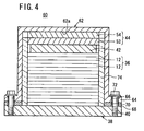
FIG. 4 is a cross sectional view showing a fuel cell stack according to a second embodiment of the present invention; -
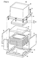
FIG. 5 is a partially-exploded perspective view showing the fuel cell stack; -
FIG. 6 is a perspective view schematically showing a fuel cell stack according to a third embodiment of the present invention; -
FIG. 7 is a partially-exploded perspective view showing the fuel cell stack; -
FIG. 8 is an exploded perspective view showing a solid oxide fuel cell of the fuel cell stack; -
FIG. 9 is a view showing a second plate of the solid oxide fuel cell; -
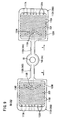
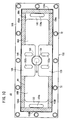
FIG. 10 is a plan view, partially in cross section, showing the fuel cell stack; -
FIG. 11 is a cross sectional view showing a flat plate type solid oxide fuel cell disclosed in Japanese Laid-Open Patent Publication No.2006-339035 -
FIG. 12 is a cross sectional view showing a fuel cell disclosed in Japanese Laid-Open Patent Publication No.2007-073359 - As shown in
FIGS. 1 and2 , afuel cell stack 10 according to a first embodiment of the present invention is formed by stacking a plurality of solidoxide fuel cells 12 in a vertical direction indicated by an arrow C. Thefuel cell stack 10 is used in various applications, including stationary and mobile applications. For example, thefuel cell stack 10 is mounted on a vehicle. The solidoxide fuel cell 12 performs power generation by electrochemical reactions of a fuel gas (hydrogen-containing gas such as a mixed gas of hydrogen gas, methane, and carbon monoxide) and an oxygen-containing gas (air). - As shown in
FIG. 3 , a solidoxide fuel cell 12 includeselectrolyte electrode assemblies 20. Each of the electrolyte electrode assembly (MEA) 20 includes acathode 16, ananode 18, and an electrolyte (electrolyte plate) 14 interposed between thecathode 16 and theanode 18. For example, the electrolyte 14 is made of ion-conductive oxide such as stabilized zirconia. The surface area of thecathode 16 is smaller than the surface areas of theanode 18 and the electrolyte 14. Acurrent collector 19 is stacked on thecathode 16. Thecurrent collector 19 has substantially the same size as thecathode 16. For example, thecurrent collector 19 is in the form of foamed metal or metal mesh containing metal such as nickel. - The
electrolyte electrode assembly 20 has a rectangular shape or a square shape, and a barrier layer (not shown) is provided at least at the outer edge of theelectrolyte electrode assembly 20 for preventing the entry or discharge of the oxygen-containing gas and the fuel gas. - The solid
oxide fuel cell 12 includes a singleelectrolyte electrode assembly 20 sandwiched between a pair of separators (interconnectors) 22. Further,seal members metal plate 25 are interposed between theseparators 22 and theelectrolyte electrode assembly 20. For example, each of theseparators 22 is a metal plate of, e.g., stainless alloy. For example, mica material, ceramic material or the like, i.e., crustal component material, glass material, and composite material of clay and plastic may be used for theseal members metal plate 25 has a frame shape. Anopening 25a formed inside themetal plate 25 is larger than thecathode 16, and smaller than the electrolyte 14. A wall around theopening 25a of themetal plate 25 is stacked on a portion around the electrolyte 14 to have a gas sealing function between thecathode 16 and theanode 18. - The
separator 22 has a rectangular shape or a square shape. At one end of theseparator 22 in a longitudinal direction indicated by an arrow A, a plurality of, e.g., three oxygen-containinggas supply passages 26a are arranged in a lateral direction indicated by an arrow B. At the other end of theseparator 22 in the longitudinal direction indicated by the arrow A, a plurality of, e.g., three oxygen-containinggas discharge passages 26b are arranged in the direction indicated by the arrow B. - At one end of the
separator 22 in the lateral direction indicated by the arrow B, for example, three fuelgas supply passages 28a are arranged in the direction indicated by the arrow A. At the other end of theseparator 22 in the lateral direction, for example, three fuelgas discharge passages 28b are arranged in the direction indicated by the arrow A. - The
separator 22 has an oxygen-containinggas channel 30 on itssurface 22a facing thecathode 16 of theelectrolyte electrode assembly 20 for supplying the oxygen-containing gas along the electrode surface of thecathode 16. The oxygen-containinggas channel 30 includes a plurality of flow grooves extending in the direction indicated by the arrow A. Both ends of the oxygen-containinggas channel 30 are terminated adjacent to the oxygen-containinggas supply passages 26a and the oxygen-containinggas discharge passages 26b. - The
separator 22 has afuel gas channel 32 on itssurface 22b facing theanode 18 of theelectrolyte electrode assembly 20 for supplying a fuel gas along the electrode surface of theanode 18. - The
fuel gas channel 32 includes a plurality of flow grooves extending in the direction indicated by the arrow B. Both ends of thefuel gas channel 32 are connected to the fuelgas supply passages 28a and the fuelgas discharge passages 28b. - The oxygen-containing
gas supply passages 26a, the oxygen-containinggas discharge passages 26b, the fuelgas supply passages 28a, and the fuelgas discharge passages 28b are formed in theseal members Inlet connection channels 34a for connecting the oxygen-containinggas supply passage 26a and the oxygen-containinggas channel 30 andoutlet connection channels 34b for connecting the oxygen-containinggas discharge passage 26b and the oxygen-containinggas channel 30 are formed in theseal member - As shown in
FIGS. 1 and2 , a plurality of the solidoxide fuel cells 12 are stacked together in the direction indicated by the arrow C to form astack body 36. Thestack body 36 is placed on a lower end plate (base member) 38 positioned at a lower end (one end) of thestack body 36 in the stacking direction indicated by the arrow C. - The dimensions of the
lower end plate 38 in the directions indicated by the arrows A and B are larger than the dimensions of thestack body 36 in the directions indicated by the arrows A and B. The oxygen-containinggas supply passages 26a, the oxygen-containinggas discharge passages 26b, the fuelgas supply passages 28a, and the fuelgas discharge passages 28b are formed in the lower end plate 38 (seeFIG. 2 ). - A plurality of screw holes 40 are formed along the marginal portion of the
lower end plate 38. For example, the screw holes 40 are formed adjacent four corners of thelower end plate 38, and substantially central positions of the respective sides. Though not shown, manifolds for supplying and discharging the oxygen-containing gas and the fuel gas are attached to thelower end plate 38. - An
upper end plate 42 is provided at an upper end (other end) of thestack body 36 in the stacking direction. The dimensions of theupper end plate 42 in the directions indicated by the arrows A and B are the same as the dimensions of thestack body 36 in the directions indicated by the arrows A and B. Theupper end plate 42 is a flat rectangular or square plate. - A fuel
cell support member 44 and a load plate (mounting member) 46 are stacked on theupper end plate 42.Holes 48 are formed along the marginal portion of theload plate 46, andbolts 50 are inserted into theholes 48. Thebolts 50 are screwed into the screw holes 40 of thelower end plate 38. - The fuel
cell support member 44 includes analumina layer 52 and acomposite layer 54. Thealumina layer 52 is provided on thestack body 36 side, i.e., adjacent to theupper end plate 42, and thecomposite layer 54 is provided adjacent to theload plate 46. - The
alumina layer 52 is made of alumina fiber. Specifically, thealumina layer 52 is formed by impregnating crystalline alumina fiber with an organic binder for compression in the thickness direction, and removing solvent portion of the organic binder by drying. Thealumina layer 52 containing the alumina fiber has elasticity, good durability at high temperature and heat insulating property and electrically insulating property. - The
composite layer 54 is made of composite material of alumina fiber and vermiculite. Specifically, thecomposite layer 54 is formed by dispersing vermiculite particles into slurry containing crystalline alumina fiber, and produced in the same manner as the above alumina layer. - The
electrolyte electrode assembly 20 is made of material having a relatively small heat expansion coefficient in comparison with thebolt 50. Therefore, even if thebolt 50 is expanded in the axial direction, the tightening load for tightening thestack body 36 does not become significantly small due to the elasticity of thealumina layer 52. - Further, vermiculite has property to expand to a relatively large extent at high temperature. The expansion coefficient of this vermiculite is larger than the expansion coefficient of the
bolt 50. Therefore, in particular, at high temperature, the tightening load for tightening thestack body 36 does not become significantly small. - At the time of assembling the
fuel cell stack 10, after thestack body 36 is stacked on thelower end plate 38, theupper end plate 42 is stacked on thestack body 36. After thealumina layer 52 having a predetermined thickness and thecomposite layer 54 having a predetermined thickness are placed on theupper end plate 42, theload plate 46 is provided on thecomposite layer 54. - Then, the
bolts 50 are inserted into therespective holes 48 of theload plate 46. Front ends of thebolts 50 are screwed into the screw holes 40 of thelower end plate 38. In the structure, the load in the stacking direction is applied to thestack body 36, and a compression load is applied to the fuelcell support member 44. - In the fuel
cell support member 44, thealumina layer 52 and thecomposite layer 54 are compressed. After the fuelcell support member 44 applies a tightening load to generate a surface pressure required for thestack body 36, tightening of thebolts 50 is finished, and operation of assembling thefuel cell stack 10 is completed. - Operation of the
fuel cell stack 10 will be described below. - As shown in
FIG. 2 , a fuel gas (e.g., hydrogen gas) and an oxygen-containing gas (e.g., air) are supplied to thelower end plate 38 of thefuel cell stack 10 through the manifolds (not shown). The air flows vertically upward along the oxygen-containinggas supply passages 26a. - In each of the solid
oxide fuel cells 12, as shown inFIG. 3 , the air flows through theinlet connection channels 34a of theseal member 24a connected to the oxygen-containinggas supply passages 26a, and then, the air is supplied to the oxygen-containinggas channel 30 of theseparator 22. The air flows through the oxygen-containinggas channel 30 in the direction indicated by the arrow A, and the air is supplied to thecathode 16 of theelectrolyte electrode assembly 20. Then, the air is discharged into the oxygen-containinggas discharge passage 26b. - The fuel gas flows vertically upward along the fuel
gas supply passages 28a, and the fuel gas is supplied to thefuel gas channel 32 of theseparator 22 of each solidoxide fuel cell 12. The fuel gas flows in the direction indicated by the arrow B along thefuel gas channel 32, and the fuel gas is supplied to theanode 18 of theelectrolyte electrode assembly 20. Then, the fuel gas is discharged to the fuelgas discharge passage 28b. - Thus, in the
electrolyte electrode assembly 20, the fuel gas is supplied to theanode 18, and the air is supplied to thecathode 16. Thus, oxide ions flow through the electrolyte 14 toward theanode 18 for generating electricity by electrochemical reactions. - In the first embodiment, the fuel
cell support member 44 is interposed between theupper end plate 42 and theload plate 46, and the fuelcell support member 44 includes thealumina layer 52 and thecomposite layer 54. - The
composite layer 54 includes alumina fiber with elasticity, having good durability, good heat insulating property, and good electrical insulating property at high temperature. Further, thecomposite layer 54 includes vermiculite having a high heat expansion coefficient at high temperature. Therefore, thecomposite layer 54 has good heat resistance property, good heat insulating property, and good heat expansion property, and it becomes possible to reliably apply the desired tightening load to thestack body 36 because the tightening load can be easily adjusted in correspondence with the change in the temperature of thefuel cell stack 10. Thus, the stacking load applied to thefuel cell stack 10 is stabilized, and improvement in the power generation performance is achieved. - Specifically, the
bolt 50 is made of material having a large linear expansion coefficient such as nickel based heat resistant alloy. The heat expansion of thebolt 50 is considerably large in comparison with theelectrolyte electrode assembly 20. Therefore, at high temperature, thebolt 50 is expanded in the stacking direction to a greater extent in comparison with thestack body 36. Therefore, the tightening load applied to thestack body 36 tends to be small. - At high temperature, heat expansion of vermiculite is large in comparison with the heat expansion of the
bolt 50 in the axial direction. Therefore, it becomes possible to suitably suppress reduction in the tightening load applied to thestack body 36. - Further, in the first embodiment, the
alumina layer 52 is provided adjacent to theupper end plate 42, and thecomposite layer 54 is provided adjacent to theload plate 46. Thealumina layer 52 is made of alumina fiber. The alumina fiber is elastic, and has good heat resistance at high temperature. Further, alumina fiber has good heat insulating property and good electrical insulating property. Therefore, thealumina layer 52 can be suitably provided at the end of thestack body 36 operated at high temperature. - Moreover, since the
alumina layer 52 has good heat insulating property, vermiculite of thecomposite layer 54 is not directly exposed to the heat from thestack body 36. Further, by heat expansion of the vermiculite, it becomes possible for thecomposite layer 54 to reliably apply the desired tightening load to thestack body 36, and the tightening load can be easily adjusted in correspondence with the change in the temperature of thefuel cell stack 10. - Since the
alumina layer 52 has a considerably small Young's modulus, a large dimensional allowance for tightening can be adopted. Therefore, the dimensional change due to the heat of thestack body 36 can be absorbed sufficiently. - Elasticity of the alumina fiber can be maintained from normal temperature to hot temperature. Therefore, from the time of assembling the
fuel cell stack 10, in the entire temperature range of operation such as steady operation and operation with load changes, the tightening load for tightening thefuel cell stack 10 can be maintained. - Further, since the alumina fiber has good heat insulating property, by providing the alumina fiber adjacent to the
upper end plate 42, heat insulating property of thefuel cell stack 10 is improved. Thus, heat radiation from thefuel cell stack 10 is suitably suppressed, thermally self-sustaining operation can be facilitated, and improvement in the stack efficiency is achieved easily. - The
fuel cell stack 10 is formed by stacking the solidoxide fuel cells 12 in the form of flat plates. Therefore, in particular, high temperature fuel cells such as the flat plate type solid oxide fuel cells can be used effectively. -
FIG. 5 is a perspective view schematically showing afuel cell stack 60 according to a second embodiment of the present invention. - The constituent elements that are identical to those of the
fuel cell stack 10 according to the first embodiment are labeled with the same reference numerals, and description thereof will be omitted. Also in a third embodiment as described later, the constituent elements that are identical to those of thefuel cell stack 10 according to the first embodiment are labeled with the same reference numerals, and description thereof will be omitted. - As shown in
FIGS. 4 and5 , thefuel cell stack 60 includes abox 62 instead of theload plate 46 according to the first embodiment. For example, thebox 62 is made of ferrite stainless material. At an end adjacent to the opening, aflange 64 protruding to the outside is provided, and a plurality ofholes 66 are formed in theflange 64. - A
seal member 68 is provided on thelower end plate 38. Theseal member 68 has a frame shape, and a plurality ofholes 70 are formed in theseal member 68 coaxially with theholes 66. -
Bolts 72 are inserted into theholes bolts 72 are screwed into the screw holes 40 of thelower end plate 38 such that the bottom (mounting member) 62a of thebox 62 presses the fuelcell support member 44 in the stacking direction. In thebox 62,heat insulating member 74 is provided around thestack body 36. For example, theheat insulating member 74 has a rectangular shape, and made of mica, for example. - In the second embodiment, the heat expansion coefficient of vermiculite of the
composite layer 54 is larger than the heat expansion coefficient of thebox 62. Therefore, it becomes possible to suitably suppress reduction in the tightening load applied to thestack body 36 due to the expansion of thebox 62 at high temperature. Thus, the same advantages as in the case of the first embodiment are obtained. For example, the desired tightening load is reliably applied to thestack body 36, and improvement in the power generation performance of the entirefuel cell stack 60 is achieved easily. - Further, in the second embodiment, the
box 62 is made of ferrite stainless material. The ferrite stainless material is inexpensive, and has a small linear expansion coefficient. Therefore, the difference in the heat expansion between thebox 62 and thestack body 36 becomes small, and further reduction in the load at high temperature is achieved. Moreover, the amount of heat resistant alloy used for thefuel cell stack 60 can be reduced, and thefuel cell stack 60 can be produced economically. - Further, in the
box 62, theheat insulating member 74 is provided along side walls of thestack body 36. Thus, thebox 62 has air-tight structure, and radiation of heat from thestack body 36 is suppressed, and improvement in the power generation efficiency is achieved easily. -
FIG. 6 is a perspective view schematically showing afuel cell stack 80 according to a third embodiment of the present invention. - As shown in
FIGS. 6 and7 , thefuel cell stack 80 includes a plurality of solidoxide fuel cells 82 stacked in a direction indicated by an arrow C. A plurality of the solidoxide fuel cells 82 are stacked together to form astack body 84. - As shown in
FIG. 8 , the solidoxide fuel cell 82 includes a pair ofseparators 86 sandwiching twoelectrolyte electrode assemblies 20 positioned in the same plane. Theseparator 86 includes afirst plate 88 and asecond plate 90. For example, thefirst plate 88 and thesecond plate 90 are metal plates of stainless alloy or the like, and are joined to each other, e.g., by brazing, diffusion bonding, or laser welding. - The
separator 86 has a fuel gas supply section (reactant gas supply section) 94, and a fuel gas supply passage (reactant gas supply passage) 92 extends through the center of the fuelgas supply section 94. A pair ofbridge sections gas supply section 94, and thebridge sections sections bridge sections gas supply section 94 positioned at the center. - The
first plate 88 includes a firstcircular disk 100, and the fuelgas supply passage 92 extends through the firstcircular disk 100. Firstlong plates circular disk 100. The firstlong plates circular disk 100 in directions opposite to each other. Firstrectangular sections long plates protrusions rectangular sections cathodes 16. Oxygen-containinggas channels protrusions - The
second plate 90 has a secondcircular disk 108, and the fuelgas supply passage 92 extends through the center of the secondcircular disk 108. Secondlong plates circular disk 108, and the secondlong plates circular disk 108 in directions opposite to each other. Secondrectangular sections long plates - Fuel
gas supply channels long plates rectangular sections Fuel gas inlets gas supply channels fuel 117B are formed on surfaces of the secondgas outlets 117Arectangular sections gas supply channels - As shown in
FIG. 9 , a plurality ofprotrusions rectangular sections anodes 18.Fuel gas channels protrusions fuel gas channels outer protrusions holes fuel gas outlets fuel gas channels path forming walls fuel gas inlets fuel gas outlets - As shown in
FIG. 8 , oxygen-containinggas supply passages 126 are formed on both sides of thebridge sections gas channels oxide fuel cell 82 in the direction indicated by the arrow A. - In a pair of
separators 86 sandwiching theelectrolyte electrode assemblies 20, an insulatingseal 128 for sealing the fuelgas supply passage 92 is provided in each space between the fuelgas supply sections 94. For example, mica material, ceramic material or the like, i.e., crustal component material, glass material, and composite material of clay and plastic may be used for the insulatingseal 128. - In each solid
oxide fuel cell 82, exhaustgas discharge passages 130 are formed around the sandwichingsections electrolyte electrode assembly 20 are discharged as the exhaust gas from the exhaustgas discharge passages 130 in the stacking direction. - As shown in
FIGS. 6 and7 , thefuel cell stack 80 includes alower end plate 132 provided at a lower end (one end) in the stacking direction of thestack body 84,upper end plates sections stack body 84, and afuel seal plate 136 provided at a position corresponding to the fuelgas supply section 94. - A first fuel
cell support member 138 is placed on thefuel seal plate 136, and second fuelcell support members upper end plates - The first fuel
cell support member 138 includes analumina layer 142 adjacent to thefuel seal plate 136, and acomposite layer 144 stacked on thealumina layer 142. Thealumina layer 142 and thecomposite layer 144 have a circular disk shape corresponding to thefuel seal plate 136. - The second fuel
cell support members alumina layers upper end plates composite layers - The alumina layers 142, 52A, 52B have structure identical to that of the
alumina layer 52. The composite layers 144, 54A, 54B have structure identical to that of thecomposite layer 54. - For example, the first fuel
cell support member 138 includes alumina fiber having a large compression amount, or having a large density, for allowing a large load to be applied in the stacking direction indicated by the arrow C, in comparison with the second fuelcell support members - The
fuel cell stack 80 has abox 146, and aflange 148 is formed at an end of the opening of thebox 146, and aseal member 150 is interposed between theflange 148 and thelower end plate 132. Theflange 148 and thelower end plate 132 are fixed together using a plurality ofbolts 72. - As shown in
FIG. 10 , twoair holes 152a and twoair holes 152b connected to the oxygen-containinggas supply passage 126, and twoexhaust gas holes gas discharge passages 130 are formed in thelower end plate 132. Further, onefuel gas hole 155 connected to the fuelgas supply passage 92 is formed in thelower end plate 132. - As shown in
FIGS. 6 ,7 , and10 , threeheat insulating members 156A and threeheat insulating members 156B are placed around three sides of each of the sandwichingsections stack body 84 and thebox 146. For example, theheat insulating members - Operation of the
fuel cell stack 80 will be described below. - A fuel gas is supplied from the
fuel gas hole 155 of thelower end plate 132 into the fuelgas supply passage 92 of thefuel cell stack 80. The air is supplied from theair holes lower end plate 132 into the oxygen-containinggas supply passage 126 of thefuel cell stack 80. - As shown in
FIG. 8 , in theseparator 86 of each solidoxide fuel cell 82, the fuel gas supplied to the fuelgas supply passage 92 is supplied into the fuelgas supply channels bridge sections gas supply channels fuel gas inlets fuel gas channels - As shown in
FIG. 9 , by the guidance of the detourpath forming walls fuel gas channels fuel gas channels anodes 18 of theelectrolyte electrode assemblies 20. Then, the fuel gas is discharged into the exhaustgas discharge passages 130 through thefuel gas outlets - The air supplied to the oxygen-containing
gas supply passages 126 flows into the oxygen-containinggas channels cathodes 16 of theelectrolyte electrode assemblies 20 and theseparator 86. Then, the oxygen-containing gas moves through the oxygen-containinggas channels cathodes 16 of theelectrolyte electrode assemblies 20. Then, the oxygen-containing gas is discharged into the exhaustgas discharge passage 130. - In the third embodiment, the first fuel
cell support member 138 for applying a load to the fuelgas supply section 94 in the stacking direction and the second fuelcell support members sections electrolyte electrode assemblies 20, in the stacking direction are provided. - The first fuel
cell support member 138 applies a large load in the stacking direction, in comparison with the second fuelcell support members gas supply section 94, the sealing performance of the fuelgas supply section 94 is maintained suitably. - In the meanwhile, a relatively small load enough to achieve tight contact between the
electrolyte electrode assemblies 20 and the sandwichingsections electrolyte electrode assemblies 20. Therefore, damages of theelectrolyte electrode assemblies 20 are prevented as much as possible, and power generation and current collection can be performed efficiently. Further, in the third embodiment, the same advantages as in the cases of the first and second embodiments are obtained.
Claims (5)
- A fuel cell stack (10) including a stack body (36) formed by stacking a plurality of solid oxide fuel cells (12), the solid oxide fuel cells (12) each formed by stacking an electrolyte electrode assembly (20) between separators (22), the electrolyte electrode assembly (20) including an anode (18), a cathode (16), and an electrolyte (14) interposed between the anode (18) and the cathode (16), the fuel cell stack (10) comprising:a base member (38) provided at one end of the stack body (36) in a stacking direction;a mounting member (46) provided at another end of the stack body (36) in the stacking direction for applying a load to the stack body (36) in the stacking direction; anda fuel cell support member (44) positioned between the mounting member (46) and the stack body (36),characterized in thatthe fuel cell support member (44) comprises an alumina layer (52) made of alumina fiber and a composite layer (54) made of a composite material of alumina fiber and vermiculite, andwherein the alumina layer (52) is provided adjacent to the stack body (36), and the composite layer (54) is provided adjacent to the mounting member.
- The fuel cell stack according to claim 1, wherein the mounting member is a plate member (46) provided in parallel with the base member (38); and
the plate member (46) and the base member (38) are tightened together in the stacking direction using a plurality of bolts (50). - The fuel cell stack according to claim 1, wherein the mounting member is formed by a bottom (62a) of a box (62) containing the stack body (36), and an end of an opening of the box (62) is tightened in the stacking direction using a plurality of bolts (72), adjacent to the base member (38).
- The fuel cell stack according to claim 1, wherein the separator (86) comprises:a sandwiching section (98A, 98B) sandwiching the electrolyte electrode assembly (20), a fuel gas channel (32A, 32B) for supplying a fuel gas along an electrode surface of the anode (18) and an oxygen-containing gas channel (30A, 30B) for supplying an oxygen-containing gas along an electrode surface of the cathode (16) being provided separately in the sandwiching section (98A, 98B);a bridge section (96A, 96B) connected to the sandwiching section (98A, 98B), a reactant gas supply channel (114A, 114B) for supplying the fuel gas to the fuel gas channel (32A, 32B) or supplying the oxygen-containing gas to the oxygen-containing gas channel (30A, 30B) being formed in the bridge section (96A, 96B); anda reactant gas supply section (94) connected to the bridge section (96A, 96B), a reactant gas supply passage (92) for supplying the fuel gas or the oxygen-containing gas to the reactant gas supply channel (114A, 114B) extending through the reactant gas supply section (94) in the stacking direction, andwherein the fuel cell support member includes a first fuel cell support member (138) for applying a load to the reactant gas supply section (94) in the stacking direction, and a second fuel cell support member (140A, 140B) for applying a load to the sandwiching section (98A, 98B) corresponding to the electrolyte electrode assembly (20), in the stacking direction; andthe load applied by the first fuel cell support member (138) is larger than the load applied by the second fuel cell support member (140A, 140B), in the stacking direction.
- The fuel cell stack according to claim 1, wherein the solid oxide fuel cell (12) is a flat plate stack type solid oxide fuel cell.
Applications Claiming Priority (2)
| Application Number | Priority Date | Filing Date | Title |
|---|---|---|---|
| JP2010267952A JP5437222B2 (en) | 2010-12-01 | 2010-12-01 | Fuel cell stack |
| PCT/JP2011/075232 WO2012073640A1 (en) | 2010-12-01 | 2011-10-26 | Fuel cell stack |
Publications (2)
| Publication Number | Publication Date |
|---|---|
| EP2647076A1 EP2647076A1 (en) | 2013-10-09 |
| EP2647076B1 true EP2647076B1 (en) | 2014-12-10 |
Family
ID=45003018
Family Applications (1)
| Application Number | Title | Priority Date | Filing Date |
|---|---|---|---|
| EP11785799.5A Not-in-force EP2647076B1 (en) | 2010-12-01 | 2011-10-26 | Fuel cell stack |
Country Status (4)
| Country | Link |
|---|---|
| US (1) | US9054350B2 (en) |
| EP (1) | EP2647076B1 (en) |
| JP (1) | JP5437222B2 (en) |
| WO (1) | WO2012073640A1 (en) |
Families Citing this family (14)
| Publication number | Priority date | Publication date | Assignee | Title |
|---|---|---|---|---|
| JP5684665B2 (en) * | 2011-07-13 | 2015-03-18 | 本田技研工業株式会社 | Fuel cell stack |
| JP5684664B2 (en) * | 2011-07-13 | 2015-03-18 | 本田技研工業株式会社 | Fuel cell stack |
| US10075471B2 (en) | 2012-06-07 | 2018-09-11 | Amazon Technologies, Inc. | Data loss prevention techniques |
| CA2897879C (en) * | 2013-01-21 | 2021-06-22 | Flexitallic Investments, Inc. | Gasket for fuel cells |
| JP6175410B2 (en) * | 2013-06-28 | 2017-08-02 | 日本特殊陶業株式会社 | Fuel cell and manufacturing method thereof |
| JP6054912B2 (en) * | 2013-06-28 | 2016-12-27 | 日本特殊陶業株式会社 | Fuel cell and manufacturing method thereof |
| JP6290676B2 (en) * | 2014-03-25 | 2018-03-07 | 東京瓦斯株式会社 | Fuel cell |
| JP6628224B2 (en) * | 2015-12-07 | 2020-01-08 | パナソニックIpマネジメント株式会社 | High temperature operation fuel cell |
| FR3045215B1 (en) * | 2015-12-15 | 2023-03-03 | Commissariat Energie Atomique | AUTONOMOUS CLAMPING SYSTEM FOR A SOEC/SOFC TYPE SOLID OXIDE STACK AT HIGH TEMPERATURE |
| KR20230088513A (en) | 2017-05-04 | 2023-06-19 | 버사 파워 시스템스 리미티드 | Compact high temperature electrochemical cell stack architecture |
| JP6596039B2 (en) * | 2017-05-25 | 2019-10-23 | 本田技研工業株式会社 | Fuel cell stack |
| JP7140590B2 (en) * | 2018-07-24 | 2022-09-21 | 株式会社東芝 | electrochemical cell stack |
| WO2021062465A1 (en) * | 2019-10-04 | 2021-04-08 | Redflow R&D Pty Ltd | Welded flowing electrolyte battery cell stack |
| GB201917650D0 (en) | 2019-12-03 | 2020-01-15 | Ceres Ip Co Ltd | Cell unit and cell stack |
Family Cites Families (10)
| Publication number | Priority date | Publication date | Assignee | Title |
|---|---|---|---|---|
| JPH0636783A (en) * | 1992-07-17 | 1994-02-10 | Mitsubishi Heavy Ind Ltd | Fuel electrode current collector for flat type solid electrolyte fuel cell |
| JPH09139223A (en) | 1995-11-14 | 1997-05-27 | Tokyo Gas Co Ltd | Lamination compressing device for flat solid electrolytic fuel cell |
| JP4291299B2 (en) | 2005-06-02 | 2009-07-08 | 日本電信電話株式会社 | Flat type solid oxide fuel cell |
| NO20053220D0 (en) | 2005-06-29 | 2005-06-29 | Norsk Hydro As | Compression of a PEM cell stack in a pressure tank. |
| JP4892897B2 (en) | 2005-09-07 | 2012-03-07 | 三菱マテリアル株式会社 | Fuel cell |
| DE102006060809A1 (en) * | 2006-12-21 | 2008-06-26 | Enerday Gmbh | Insulating and bracing device for a high temperature fuel cell system component |
| US7858259B2 (en) * | 2007-01-26 | 2010-12-28 | Topsoe Fuel Cell A/S | Fuel cell stack clamping structure and solid oxide fuel cell stack |
| DK2109912T3 (en) * | 2007-01-26 | 2011-01-10 | Topsoe Fuel Cell As | Clamp structure for fuel cell stack as well as solid oxide fuel cell stack |
| JP5383051B2 (en) * | 2008-01-21 | 2014-01-08 | 本田技研工業株式会社 | Fuel cell and fuel cell stack |
| JP5449411B2 (en) * | 2009-03-13 | 2014-03-19 | トプサー・フューエル・セル・アクチエゼルスカベット | COMPRESSION CASING FOR FUEL CELL STACK AND METHOD FOR PRODUCING COMPRESSION CASING FOR FUEL CELL STACK |
-
2010
- 2010-12-01 JP JP2010267952A patent/JP5437222B2/en not_active Expired - Fee Related
-
2011
- 2011-10-26 US US13/824,245 patent/US9054350B2/en active Active
- 2011-10-26 EP EP11785799.5A patent/EP2647076B1/en not_active Not-in-force
- 2011-10-26 WO PCT/JP2011/075232 patent/WO2012073640A1/en active Application Filing
Also Published As
| Publication number | Publication date |
|---|---|
| US9054350B2 (en) | 2015-06-09 |
| JP5437222B2 (en) | 2014-03-12 |
| US20130177829A1 (en) | 2013-07-11 |
| WO2012073640A1 (en) | 2012-06-07 |
| JP2012119164A (en) | 2012-06-21 |
| EP2647076A1 (en) | 2013-10-09 |
Similar Documents
| Publication | Publication Date | Title |
|---|---|---|
| EP2647076B1 (en) | Fuel cell stack | |
| US9318758B2 (en) | SOFC stack with temperature adapted compression force means | |
| US9252449B2 (en) | SOFC stack with temperature adapted compression force means | |
| US10297854B2 (en) | Fuel cell stack | |
| US8530107B2 (en) | Solid oxide fuel cell manifold and corresponding stack | |
| US7569301B2 (en) | Fuel cell | |
| US20190245236A1 (en) | Polymer electrolyte fuel cell stack | |
| US20080014492A1 (en) | Compression assembly, solid oxide fuel cell stack, a process for compression of the solid oxide fuel cell stack and its use | |
| EP1685621B1 (en) | Multi-cell fuel layer and system | |
| US7368199B2 (en) | Fuel cell stack | |
| JP6702585B2 (en) | Flat electrochemical cell stack | |
| WO2006090464A1 (en) | Solid polymer fuel cell and method for producing same | |
| KR101162669B1 (en) | Solid oxide fuel cell | |
| US8557467B2 (en) | Fuel cell and fuel cell stack | |
| KR100808028B1 (en) | Equivalent large-area fuel cell with a planar array of unit cells and compressive sealant therefor | |
| JP7082954B2 (en) | Electrochemical reaction cell stack | |
| JPWO2018167845A1 (en) | Flat plate type electrochemical cell stack | |
| JP6403569B2 (en) | Fuel cell hot module | |
| JP2007134163A (en) | Polymer electrolyte fuel cell |
Legal Events
| Date | Code | Title | Description |
|---|---|---|---|
| PUAI | Public reference made under article 153(3) epc to a published international application that has entered the european phase |
Free format text: ORIGINAL CODE: 0009012 |
|
| 17P | Request for examination filed |
Effective date: 20130318 |
|
| AK | Designated contracting states |
Kind code of ref document: A1 Designated state(s): AL AT BE BG CH CY CZ DE DK EE ES FI FR GB GR HR HU IE IS IT LI LT LU LV MC MK MT NL NO PL PT RO RS SE SI SK SM TR |
|
| DAX | Request for extension of the european patent (deleted) | ||
| GRAP | Despatch of communication of intention to grant a patent |
Free format text: ORIGINAL CODE: EPIDOSNIGR1 |
|
| INTG | Intention to grant announced |
Effective date: 20140724 |
|
| GRAS | Grant fee paid |
Free format text: ORIGINAL CODE: EPIDOSNIGR3 |
|
| GRAA | (expected) grant |
Free format text: ORIGINAL CODE: 0009210 |
|
| AK | Designated contracting states |
Kind code of ref document: B1 Designated state(s): AL AT BE BG CH CY CZ DE DK EE ES FI FR GB GR HR HU IE IS IT LI LT LU LV MC MK MT NL NO PL PT RO RS SE SI SK SM TR |
|
| REG | Reference to a national code |
Ref country code: GB Ref legal event code: FG4D |
|
| REG | Reference to a national code |
Ref country code: CH Ref legal event code: EP |
|
| REG | Reference to a national code |
Ref country code: IE Ref legal event code: FG4D |
|
| REG | Reference to a national code |
Ref country code: AT Ref legal event code: REF Ref document number: 701066 Country of ref document: AT Kind code of ref document: T Effective date: 20150115 |
|
| REG | Reference to a national code |
Ref country code: DE Ref legal event code: R096 Ref document number: 602011012195 Country of ref document: DE Effective date: 20150122 |
|
| REG | Reference to a national code |
Ref country code: AT Ref legal event code: MK05 Ref document number: 701066 Country of ref document: AT Kind code of ref document: T Effective date: 20141210 Ref country code: NL Ref legal event code: VDEP Effective date: 20141210 |
|
| REG | Reference to a national code |
Ref country code: NL Ref legal event code: VDEP Effective date: 20141210 |
|
| PG25 | Lapsed in a contracting state [announced via postgrant information from national office to epo] |
Ref country code: FI Free format text: LAPSE BECAUSE OF FAILURE TO SUBMIT A TRANSLATION OF THE DESCRIPTION OR TO PAY THE FEE WITHIN THE PRESCRIBED TIME-LIMIT Effective date: 20141210 Ref country code: LT Free format text: LAPSE BECAUSE OF FAILURE TO SUBMIT A TRANSLATION OF THE DESCRIPTION OR TO PAY THE FEE WITHIN THE PRESCRIBED TIME-LIMIT Effective date: 20141210 Ref country code: NO Free format text: LAPSE BECAUSE OF FAILURE TO SUBMIT A TRANSLATION OF THE DESCRIPTION OR TO PAY THE FEE WITHIN THE PRESCRIBED TIME-LIMIT Effective date: 20150310 Ref country code: ES Free format text: LAPSE BECAUSE OF FAILURE TO SUBMIT A TRANSLATION OF THE DESCRIPTION OR TO PAY THE FEE WITHIN THE PRESCRIBED TIME-LIMIT Effective date: 20141210 |
|
| REG | Reference to a national code |
Ref country code: LT Ref legal event code: MG4D |
|
| PG25 | Lapsed in a contracting state [announced via postgrant information from national office to epo] |
Ref country code: GR Free format text: LAPSE BECAUSE OF FAILURE TO SUBMIT A TRANSLATION OF THE DESCRIPTION OR TO PAY THE FEE WITHIN THE PRESCRIBED TIME-LIMIT Effective date: 20150311 Ref country code: LV Free format text: LAPSE BECAUSE OF FAILURE TO SUBMIT A TRANSLATION OF THE DESCRIPTION OR TO PAY THE FEE WITHIN THE PRESCRIBED TIME-LIMIT Effective date: 20141210 Ref country code: HR Free format text: LAPSE BECAUSE OF FAILURE TO SUBMIT A TRANSLATION OF THE DESCRIPTION OR TO PAY THE FEE WITHIN THE PRESCRIBED TIME-LIMIT Effective date: 20141210 Ref country code: AT Free format text: LAPSE BECAUSE OF FAILURE TO SUBMIT A TRANSLATION OF THE DESCRIPTION OR TO PAY THE FEE WITHIN THE PRESCRIBED TIME-LIMIT Effective date: 20141210 Ref country code: SE Free format text: LAPSE BECAUSE OF FAILURE TO SUBMIT A TRANSLATION OF THE DESCRIPTION OR TO PAY THE FEE WITHIN THE PRESCRIBED TIME-LIMIT Effective date: 20141210 Ref country code: RS Free format text: LAPSE BECAUSE OF FAILURE TO SUBMIT A TRANSLATION OF THE DESCRIPTION OR TO PAY THE FEE WITHIN THE PRESCRIBED TIME-LIMIT Effective date: 20141210 |
|
| PG25 | Lapsed in a contracting state [announced via postgrant information from national office to epo] |
Ref country code: NL Free format text: LAPSE BECAUSE OF FAILURE TO SUBMIT A TRANSLATION OF THE DESCRIPTION OR TO PAY THE FEE WITHIN THE PRESCRIBED TIME-LIMIT Effective date: 20141210 |
|
| PG25 | Lapsed in a contracting state [announced via postgrant information from national office to epo] |
Ref country code: PT Free format text: LAPSE BECAUSE OF FAILURE TO SUBMIT A TRANSLATION OF THE DESCRIPTION OR TO PAY THE FEE WITHIN THE PRESCRIBED TIME-LIMIT Effective date: 20150410 Ref country code: RO Free format text: LAPSE BECAUSE OF FAILURE TO SUBMIT A TRANSLATION OF THE DESCRIPTION OR TO PAY THE FEE WITHIN THE PRESCRIBED TIME-LIMIT Effective date: 20141210 Ref country code: EE Free format text: LAPSE BECAUSE OF FAILURE TO SUBMIT A TRANSLATION OF THE DESCRIPTION OR TO PAY THE FEE WITHIN THE PRESCRIBED TIME-LIMIT Effective date: 20141210 Ref country code: CZ Free format text: LAPSE BECAUSE OF FAILURE TO SUBMIT A TRANSLATION OF THE DESCRIPTION OR TO PAY THE FEE WITHIN THE PRESCRIBED TIME-LIMIT Effective date: 20141210 Ref country code: SK Free format text: LAPSE BECAUSE OF FAILURE TO SUBMIT A TRANSLATION OF THE DESCRIPTION OR TO PAY THE FEE WITHIN THE PRESCRIBED TIME-LIMIT Effective date: 20141210 |
|
| PG25 | Lapsed in a contracting state [announced via postgrant information from national office to epo] |
Ref country code: PL Free format text: LAPSE BECAUSE OF FAILURE TO SUBMIT A TRANSLATION OF THE DESCRIPTION OR TO PAY THE FEE WITHIN THE PRESCRIBED TIME-LIMIT Effective date: 20141210 Ref country code: IS Free format text: LAPSE BECAUSE OF FAILURE TO SUBMIT A TRANSLATION OF THE DESCRIPTION OR TO PAY THE FEE WITHIN THE PRESCRIBED TIME-LIMIT Effective date: 20150410 |
|
| REG | Reference to a national code |
Ref country code: DE Ref legal event code: R097 Ref document number: 602011012195 Country of ref document: DE |
|
| PLBE | No opposition filed within time limit |
Free format text: ORIGINAL CODE: 0009261 |
|
| STAA | Information on the status of an ep patent application or granted ep patent |
Free format text: STATUS: NO OPPOSITION FILED WITHIN TIME LIMIT |
|
| PG25 | Lapsed in a contracting state [announced via postgrant information from national office to epo] |
Ref country code: DK Free format text: LAPSE BECAUSE OF FAILURE TO SUBMIT A TRANSLATION OF THE DESCRIPTION OR TO PAY THE FEE WITHIN THE PRESCRIBED TIME-LIMIT Effective date: 20141210 |
|
| 26N | No opposition filed |
Effective date: 20150911 |
|
| PG25 | Lapsed in a contracting state [announced via postgrant information from national office to epo] |
Ref country code: IT Free format text: LAPSE BECAUSE OF FAILURE TO SUBMIT A TRANSLATION OF THE DESCRIPTION OR TO PAY THE FEE WITHIN THE PRESCRIBED TIME-LIMIT Effective date: 20141210 |
|
| PG25 | Lapsed in a contracting state [announced via postgrant information from national office to epo] |
Ref country code: SI Free format text: LAPSE BECAUSE OF FAILURE TO SUBMIT A TRANSLATION OF THE DESCRIPTION OR TO PAY THE FEE WITHIN THE PRESCRIBED TIME-LIMIT Effective date: 20141210 |
|
| PG25 | Lapsed in a contracting state [announced via postgrant information from national office to epo] |
Ref country code: BE Free format text: LAPSE BECAUSE OF FAILURE TO SUBMIT A TRANSLATION OF THE DESCRIPTION OR TO PAY THE FEE WITHIN THE PRESCRIBED TIME-LIMIT Effective date: 20141210 Ref country code: LU Free format text: LAPSE BECAUSE OF FAILURE TO SUBMIT A TRANSLATION OF THE DESCRIPTION OR TO PAY THE FEE WITHIN THE PRESCRIBED TIME-LIMIT Effective date: 20151026 |
|
| REG | Reference to a national code |
Ref country code: CH Ref legal event code: PL |
|
| PG25 | Lapsed in a contracting state [announced via postgrant information from national office to epo] |
Ref country code: MC Free format text: LAPSE BECAUSE OF FAILURE TO SUBMIT A TRANSLATION OF THE DESCRIPTION OR TO PAY THE FEE WITHIN THE PRESCRIBED TIME-LIMIT Effective date: 20141210 |
|
| REG | Reference to a national code |
Ref country code: IE Ref legal event code: MM4A |
|
| PG25 | Lapsed in a contracting state [announced via postgrant information from national office to epo] |
Ref country code: LI Free format text: LAPSE BECAUSE OF NON-PAYMENT OF DUE FEES Effective date: 20151031 Ref country code: CH Free format text: LAPSE BECAUSE OF NON-PAYMENT OF DUE FEES Effective date: 20151031 |
|
| REG | Reference to a national code |
Ref country code: FR Ref legal event code: ST Effective date: 20160630 |
|
| PG25 | Lapsed in a contracting state [announced via postgrant information from national office to epo] |
Ref country code: FR Free format text: LAPSE BECAUSE OF NON-PAYMENT OF DUE FEES Effective date: 20151102 |
|
| PG25 | Lapsed in a contracting state [announced via postgrant information from national office to epo] |
Ref country code: IE Free format text: LAPSE BECAUSE OF NON-PAYMENT OF DUE FEES Effective date: 20151026 |
|
| PG25 | Lapsed in a contracting state [announced via postgrant information from national office to epo] |
Ref country code: BG Free format text: LAPSE BECAUSE OF FAILURE TO SUBMIT A TRANSLATION OF THE DESCRIPTION OR TO PAY THE FEE WITHIN THE PRESCRIBED TIME-LIMIT Effective date: 20141210 Ref country code: SM Free format text: LAPSE BECAUSE OF FAILURE TO SUBMIT A TRANSLATION OF THE DESCRIPTION OR TO PAY THE FEE WITHIN THE PRESCRIBED TIME-LIMIT Effective date: 20141210 Ref country code: HU Free format text: LAPSE BECAUSE OF FAILURE TO SUBMIT A TRANSLATION OF THE DESCRIPTION OR TO PAY THE FEE WITHIN THE PRESCRIBED TIME-LIMIT; INVALID AB INITIO Effective date: 20111026 |
|
| PG25 | Lapsed in a contracting state [announced via postgrant information from national office to epo] |
Ref country code: CY Free format text: LAPSE BECAUSE OF FAILURE TO SUBMIT A TRANSLATION OF THE DESCRIPTION OR TO PAY THE FEE WITHIN THE PRESCRIBED TIME-LIMIT Effective date: 20141210 |
|
| PG25 | Lapsed in a contracting state [announced via postgrant information from national office to epo] |
Ref country code: MT Free format text: LAPSE BECAUSE OF FAILURE TO SUBMIT A TRANSLATION OF THE DESCRIPTION OR TO PAY THE FEE WITHIN THE PRESCRIBED TIME-LIMIT Effective date: 20141210 |
|
| PG25 | Lapsed in a contracting state [announced via postgrant information from national office to epo] |
Ref country code: TR Free format text: LAPSE BECAUSE OF FAILURE TO SUBMIT A TRANSLATION OF THE DESCRIPTION OR TO PAY THE FEE WITHIN THE PRESCRIBED TIME-LIMIT Effective date: 20141210 Ref country code: MK Free format text: LAPSE BECAUSE OF FAILURE TO SUBMIT A TRANSLATION OF THE DESCRIPTION OR TO PAY THE FEE WITHIN THE PRESCRIBED TIME-LIMIT Effective date: 20141210 |
|
| PG25 | Lapsed in a contracting state [announced via postgrant information from national office to epo] |
Ref country code: AL Free format text: LAPSE BECAUSE OF FAILURE TO SUBMIT A TRANSLATION OF THE DESCRIPTION OR TO PAY THE FEE WITHIN THE PRESCRIBED TIME-LIMIT Effective date: 20141210 |
|
| PGFP | Annual fee paid to national office [announced via postgrant information from national office to epo] |
Ref country code: GB Payment date: 20191024 Year of fee payment: 9 |
|
| GBPC | Gb: european patent ceased through non-payment of renewal fee |
Effective date: 20201026 |
|
| PG25 | Lapsed in a contracting state [announced via postgrant information from national office to epo] |
Ref country code: GB Free format text: LAPSE BECAUSE OF NON-PAYMENT OF DUE FEES Effective date: 20201026 |
|
| PGFP | Annual fee paid to national office [announced via postgrant information from national office to epo] |
Ref country code: DE Payment date: 20210914 Year of fee payment: 11 |
|
| REG | Reference to a national code |
Ref country code: DE Ref legal event code: R119 Ref document number: 602011012195 Country of ref document: DE |
|
| PG25 | Lapsed in a contracting state [announced via postgrant information from national office to epo] |
Ref country code: DE Free format text: LAPSE BECAUSE OF NON-PAYMENT OF DUE FEES Effective date: 20230503 |