JP5434969B2 - Vehicle seat reclining device - Google Patents
Vehicle seat reclining device Download PDFInfo
- Publication number
- JP5434969B2 JP5434969B2 JP2011132411A JP2011132411A JP5434969B2 JP 5434969 B2 JP5434969 B2 JP 5434969B2 JP 2011132411 A JP2011132411 A JP 2011132411A JP 2011132411 A JP2011132411 A JP 2011132411A JP 5434969 B2 JP5434969 B2 JP 5434969B2
- Authority
- JP
- Japan
- Prior art keywords
- pole
- cam
- arm
- pressing member
- pressing
- Prior art date
- Legal status (The legal status is an assumption and is not a legal conclusion. Google has not performed a legal analysis and makes no representation as to the accuracy of the status listed.)
- Expired - Fee Related
Links
Images


Classifications
-
- B—PERFORMING OPERATIONS; TRANSPORTING
- B60—VEHICLES IN GENERAL
- B60N—SEATS SPECIALLY ADAPTED FOR VEHICLES; VEHICLE PASSENGER ACCOMMODATION NOT OTHERWISE PROVIDED FOR
- B60N2/00—Seats specially adapted for vehicles; Arrangement or mounting of seats in vehicles
- B60N2/02—Seats specially adapted for vehicles; Arrangement or mounting of seats in vehicles the seat or part thereof being movable, e.g. adjustable
- B60N2/22—Seats specially adapted for vehicles; Arrangement or mounting of seats in vehicles the seat or part thereof being movable, e.g. adjustable the back-rest being adjustable
- B60N2/235—Seats specially adapted for vehicles; Arrangement or mounting of seats in vehicles the seat or part thereof being movable, e.g. adjustable the back-rest being adjustable by gear-pawl type mechanisms
- B60N2/2356—Seats specially adapted for vehicles; Arrangement or mounting of seats in vehicles the seat or part thereof being movable, e.g. adjustable the back-rest being adjustable by gear-pawl type mechanisms with internal pawls
- B60N2/236—Seats specially adapted for vehicles; Arrangement or mounting of seats in vehicles the seat or part thereof being movable, e.g. adjustable the back-rest being adjustable by gear-pawl type mechanisms with internal pawls linearly movable
-
- B—PERFORMING OPERATIONS; TRANSPORTING
- B60—VEHICLES IN GENERAL
- B60N—SEATS SPECIALLY ADAPTED FOR VEHICLES; VEHICLE PASSENGER ACCOMMODATION NOT OTHERWISE PROVIDED FOR
- B60N2/00—Seats specially adapted for vehicles; Arrangement or mounting of seats in vehicles
- B60N2/02—Seats specially adapted for vehicles; Arrangement or mounting of seats in vehicles the seat or part thereof being movable, e.g. adjustable
- B60N2/22—Seats specially adapted for vehicles; Arrangement or mounting of seats in vehicles the seat or part thereof being movable, e.g. adjustable the back-rest being adjustable
- B60N2/235—Seats specially adapted for vehicles; Arrangement or mounting of seats in vehicles the seat or part thereof being movable, e.g. adjustable the back-rest being adjustable by gear-pawl type mechanisms
- B60N2/2356—Seats specially adapted for vehicles; Arrangement or mounting of seats in vehicles the seat or part thereof being movable, e.g. adjustable the back-rest being adjustable by gear-pawl type mechanisms with internal pawls
Landscapes
- Engineering & Computer Science (AREA)
- Aviation & Aerospace Engineering (AREA)
- Transportation (AREA)
- Mechanical Engineering (AREA)
- Chairs For Special Purposes, Such As Reclining Chairs (AREA)
- Seats For Vehicles (AREA)
Description
本発明は、シートクッションに対するシートバックの傾斜角度を調整するための車両用シートリクライニング装置に関するものである。 The present invention relates to a vehicle seat reclining device for adjusting an inclination angle of a seat back with respect to a seat cushion.
従来、こうした車両用シートリクライニング装置としては、例えば特許文献1に記載されたものが知られている。この車両用シートリクライニング装置は、内歯部(26,27)を有するアッパプレート(22)と、アッパプレートを軸支するロアプレート(21)と、該ロアプレートに設けられたガイド壁(21a〜21d)により径方向への移動が案内された対のポール(31,32)と、これらポールの背面側に当接可能なカム(41)と、両ポールの背面側にそれぞれ当接可能な対の押圧部材(42,42′)とを備える。そして、カムは、両押圧部材にも当接可能となっている。各ポールは、スプリング(51)により、カムを介して、あるいはカム及び押圧部材を介して、その外歯(31a,32a)が該当の内歯部に噛合する方向に付勢されている。これにより、ポールの外歯及びアッパプレートの内歯部の噛合状態が保持される。 Conventionally, as such a vehicle seat reclining device, for example, a device described in Patent Document 1 is known. The vehicle seat reclining device includes an upper plate (22) having internal teeth (26, 27), a lower plate (21) that pivotally supports the upper plate, and guide walls (21a to 21a) provided on the lower plate. 21d) a pair of poles (31, 32) guided in the radial direction, a cam (41) capable of abutting on the back side of these poles, and a pair capable of abutting on the back side of both poles Pressing members (42, 42 '). The cam can also contact both pressing members. Each pole is urged by a spring (51) via a cam or via a cam and a pressing member in a direction in which the external teeth (31a, 32a) mesh with the corresponding internal tooth portion. Thereby, the meshing state of the outer teeth of the pole and the inner teeth of the upper plate is maintained.
特に、押圧部材は、円筒形状を呈しており、対をなすガイド壁の片側及びポールの背面間に形成される楔状の空間に配置されている。この場合、図7に模式的に示したように、押圧部材のポールに対する押圧力F90は、実質的にポールの押圧点P90における接線T90の直交方向、即ち押圧点P90における法線方向に向かっている。従って、押圧部材の押圧力F90は、ポールの移動方向成分(径方向成分)の分力F91及び該移動方向に直交する方向であるポールの幅方向成分(周方向成分)の分力F92に分解される。そして、この分力F92の押圧により、ポールの幅端部と反対側のガイド壁との隙間を埋めることができ、シートのがたつきを抑制できるとしている。これは、ポールの幅方向成分(周方向成分)の分力F92が、内歯部からの外力に対する保持力として機能することによる。 In particular, the pressing member has a cylindrical shape and is disposed in a wedge-shaped space formed between one side of the pair of guide walls and the back surface of the pole. In this case, as schematically shown in FIG. 7, the pressing force F90 on the pole of the pressing member is substantially in the direction perpendicular to the tangent T90 at the pressing point P90 of the pole, that is, in the normal direction at the pressing point P90. Yes. Accordingly, the pressing force F90 of the pressing member is decomposed into a component force F91 of the pole moving direction component (radial direction component) and a component force F92 of the pole width direction component (circumferential component) which is a direction orthogonal to the moving direction. Is done. By pressing the component force F92, it is possible to fill a gap between the width end portion of the pole and the guide wall on the opposite side, and to suppress rattling of the sheet. This is because the component force F92 of the pole width direction component (circumferential direction component) functions as a holding force against the external force from the internal tooth portion.
ところで、ポールの幅方向成分の分力F92は、押圧力F90の作用方向(押圧点P90における法線方向)に対する分力F92の作用方向の傾斜角度θが小さくなるほど、即ちポールの移動方向に対する接線T90の傾斜角度θが小さくなるほど、大きくなってより堅固にシートのがたつきを抑制できる。 By the way, the component force F92 of the component in the width direction of the pole is smaller in tangent to the moving direction of the pole as the inclination angle θ of the acting direction of the component force F92 with respect to the acting direction of the pressing force F90 (normal direction at the pressing point P90) becomes smaller. The smaller the inclination angle θ of T90 is, the larger the angle is, and the more firmly the rattling of the sheet can be suppressed.
一方、ポールの幅方向成分の分力F92が大きくなるほど、押圧部材及びポールの背面が食い付きやすくなって押圧部材を解除しにくくなる。これは、押圧部材の押圧力Fに基づく摩擦力をF93で表すと、押圧部材の解除を阻害する摩擦力F93のポールの移動方向成分(径方向成分)の分力F94が、ポールの移動方向に対する接線T90の傾斜角度θが小さくなるほど、大きくなるためである。このような押圧部材及びポールの背面の食い付きを抑制するために、ポールの移動方向に対する接線Tの傾斜角度θを大きくすることも考えられるが、その場合には、ポールの幅方向成分(周方向成分)の分力F92が小さくなって前記した保持力が減少してしまう。 On the other hand, as the component force F92 of the pole width direction component increases, the pressing member and the back surface of the pole are more likely to bite and the pressing member is less likely to be released. When the frictional force based on the pressing force F of the pressing member is represented by F93, the component force F94 of the moving direction component (radial direction component) of the frictional force F93 that inhibits the release of the pressing member is the moving direction of the pole. This is because the smaller the inclination angle θ of the tangent line T90 to the larger, the larger. In order to suppress the biting of the back surface of the pressing member and the pole, it is conceivable to increase the inclination angle θ of the tangent line T with respect to the moving direction of the pole. The component force F92 of the direction component) becomes small, and the holding force described above decreases.
本発明の目的は、外歯及び内歯の噛合状態において外力に対する保持力として機能する押圧部材の押圧力におけるポールの幅方向成分の分力を好適に確保しながらも、押圧部材と共に外歯及び内歯を円滑に解除することができる車両用シートリクライニング装置を提供することにある。 The object of the present invention is to ensure the component of the component in the width direction of the pole in the pressing force of the pressing member that functions as a holding force against the external force in the meshed state of the external teeth and the internal teeth, while also ensuring the external teeth and An object of the present invention is to provide a vehicle seat reclining device capable of smoothly releasing internal teeth.
上記問題点を解決するために、請求項1に記載の発明は、シートクッション及びシートバックのいずれか一方に固定され、少なくとも一対の相対向するガイド壁を有する第1アームと、前記シートクッション及び前記シートバックの他方に固定される第2アームであって、該第2アームは、回転軸線の周りに回転可能に前記第1アームに支持され、前記回転軸線を中心とする径方向の内側へ向かって形成された複数の内歯を有する前記第2アームと、前記第2アームの内歯に噛合可能であり、かつ径方向外側へ向かって形成された複数の外歯を有する少なくとも一つのポールであって、前記各ポールは、前記各対のガイド壁の間に配置されて、該ガイド壁によって径方向に沿った移動が案内される前記ポールと、前記ポールに係合するとともに、前記回転軸線の周りに正方向および逆方向に選択的に回転可能なカムであって、前記カムが前記正方向に回転するとき、前記各ポールを径方向外側へ向かって移動させるように押圧して、前記各ポールの外歯を前記第2アームの内歯に噛合させ、前記カムが前記逆方向に回転するとき、前記各ポールを径方向内側へ向かって移動させて、前記各ポールの外歯を前記第2アームの内歯から離間させる前記カムと、前記ガイド壁のうち少なくとも一つにおける径方向内側の部位に形成され、径方向内側が前記ポールから離間するように傾斜する少なくとも一つの傾斜面と、前記傾斜面及び前記ポールの径方向内面の間に配置される少なくとも一つの押圧部材であって、前記カムが前記正方向へ回転するとき、該押圧部材は、前記カムによって径方向外側へ向かって押圧されて、前記ポールの径方向内面を押圧することにより、該傾斜面を有するガイド壁から前記ポールへの方向に前記ポールを押圧するとともに、前記ポールを径方向外側へ向かって移動させ、前記カムが前記逆方向へ回転するとき、前記押圧部材は、該カムによる押圧から解放されることで、前記ポールの径方向内面への押圧を解放して、該ポールが径方向内側へ向かって移動することを許容する前記押圧部材と、前記カムを前記正方向に向けて付勢して、前記ポールを径方向外側へ向けて移動させる付勢部材とを備えたことを要旨とする。 In order to solve the above-described problem, the invention according to claim 1 is a first arm fixed to one of a seat cushion and a seat back and having at least a pair of opposing guide walls, the seat cushion, A second arm fixed to the other side of the seat back, the second arm being supported by the first arm so as to be rotatable around a rotation axis, and radially inwardly about the rotation axis The second arm having a plurality of inner teeth formed toward the inner side, and at least one pole having a plurality of outer teeth that can mesh with the inner teeth of the second arm and are formed radially outward. Each of the poles is disposed between each of the pair of guide walls and is engaged with the pole by the guide wall and guided by the guide wall along a radial direction. , A cam that can selectively rotate around the rotation axis in the forward direction and the reverse direction, and when the cam rotates in the forward direction, the respective poles are pressed to move radially outward Then, the external teeth of the respective poles are meshed with the internal teeth of the second arm, and when the cam rotates in the opposite direction, the respective poles are moved inward in the radial direction, At least one of the cam for separating the outer teeth from the inner teeth of the second arm and the radially inner portion of at least one of the guide walls, and the radially inner side being inclined so as to be separated from the pole. At least one pressing member disposed between the inclined surface and the radially inner surface of the pole, and when the cam rotates in the positive direction, the pressing member is By pressing toward the outer side in the direction, the inner surface in the radial direction of the pole is pressed to press the pole in the direction from the guide wall having the inclined surface to the pole, and the pole is moved outward in the radial direction. When the cam rotates in the opposite direction, the pressing member is released from the pressing by the cam to release the pressing to the radially inner surface of the pole, and the pole The press member that allows the inward movement, and the urging member that urges the cam in the forward direction and moves the pole in the radially outward direction. And
請求項2に記載の発明は、請求項1に記載の車両用シートリクライニング装置において、前記押圧部材は、前記ガイド壁の各対のうちのいずれか一方にのみ配置されていることを要旨とする。 According to a second aspect of the invention, the vehicle seat reclining device according to claim 1, wherein the pressing member includes a gist that only are arranged on either one of each pair of the guide wall To do.
請求項3に記載の発明は、請求項2に記載の車両用シートリクライニング装置において、前記カムによって押圧される前記ポールの押圧部は、前記押圧部材を介して前記カムに押圧される前記ポールの径方向内面の一部分と、前記カムに直接に押圧される前記ポールの径方向内面の一つ又は二つの部分とからなり、各部分は前記ポールの径方向内面上において間隔をおいて配置されていることを要旨とする。
請求項4に記載の発明は、シートクッション及びシートバックを備える車両に設けられる車両用シートリクライニング装置であって、該車両用シートリクライニング装置は、前記シートクッション及び前記シートバックのいずれか一方に固定され、一対の相対向するガイド壁を有し、且つ円形状をなす第1アームと、前記シートクッション及び前記シートバックの他方に固定され、第1歯を有し、前記第1アームに回転自在に支持される第2アームと、前記第1歯に噛合可能な第2歯を有し、前記ガイド壁の間に配置されて、該ガイド壁によって、前記第1アームにおける径方向に沿った移動が案内されるポールと、前記第2アームに対して正方向および逆方向に選択的に回転可能に支持され、且つ前記ポールに係合するカムであって、前記カムが前記正方向に回転するとき、前記第1歯が前記第2歯に噛合するように前記ポールを前記径方向に沿って移動させ、前記カムが前記逆方向に回転するとき、前記第1歯が前記第2歯から離間するように前記ポールを前記径方向に沿って移動させる前記カムと、前記第1アームの径方向内側において前記ガイド壁の一方に形成され、かつ前記第1アームの径方向外側から前記第1アームの径方向内側に向かって前記ポールから離間するように傾斜する傾斜面と、前記傾斜面と前記ポールとの間に配置される押圧部材とを備え、前記カムが前記正方向に回転するとき、前記押圧部材が該カムに押圧されることにより前記ポールの面が押圧され、前記ポールは前記押圧部材の押圧により前記ガイド壁に押付けられつつ前記一対のガイド壁に沿って移動し、前記カムが前記逆方向に回転するとき、前記カムによる前記押圧部材への押圧が解放され、前記押圧部材による前記ポールの面への押圧が解放されて、前記一対のガイド壁に沿った径方向内側に向かう前記ポールの移動が許容されることを要旨とする。
The invention of claim 3 is the vehicle seat reclining device according to claim 2, the pressing portion of the pawl that will be pressed me by the cam, Ru is pressed to the cam via the pressing member and first portion of the radially inner surface of the pole consists of a one or two parts of the radially inner surface of the pole to the cam Ru is pressed directly to each portion in the radial direction inner surface of the pole and gist that it has been spaced.
The invention according to claim 4 is a vehicle seat reclining device provided in a vehicle including a seat cushion and a seat back, and the vehicle seat reclining device is fixed to one of the seat cushion and the seat back. A first arm having a pair of opposing guide walls and having a circular shape, and is fixed to the other of the seat cushion and the seat back, has a first tooth, and is rotatable to the first arm. A second arm supported by the first arm and a second tooth meshable with the first tooth, and is disposed between the guide walls, and moves along the radial direction of the first arm by the guide wall. A pawl that is guided, and a cam that is rotatably supported in the forward and reverse directions with respect to the second arm and that engages the pawl, When the cam rotates in the forward direction, the pole moves along the radial direction so that the first teeth mesh with the second teeth, and when the cam rotates in the reverse direction, the first teeth The cam that moves the pole along the radial direction so that the teeth are spaced apart from the second tooth; and is formed on one of the guide walls on the radial inner side of the first arm; and An inclined surface that inclines so as to be separated from the pole from the radially outer side toward the radially inner side of the first arm, and a pressing member that is disposed between the inclined surface and the pole. When rotating in the forward direction, the pressing member is pressed by the cam to press the surface of the pole, and the pole is pressed against the guide wall by the pressing member and pressed against the pair of guide walls. Along When the cam rotates in the opposite direction, the pressure on the pressing member by the cam is released, the pressure on the surface of the pole by the pressing member is released, and the pair of guide walls The gist is that the movement of the pole toward the radially inner side is allowed.
上記各構成によれば、前記付勢部材により前記カムを一方向に回転付勢すると、該カムが前記ポールに係合するとともに、前記カムに押圧される前記押圧部材が前記ポールの背面を押圧することで、該ポールは、前記両ガイド壁に沿って進出して前記外歯及び前記内歯を噛合する。これにより、前記第1及び第2アームの相対回動が規制されて、前記シートクッションに対する前記シートバックの回動が規制(ロック)される。同時に、前記押圧部材は、前記ポールを反対側の前記ガイド壁に押し付けることで、前記ポールと反対側の前記ガイド壁との隙間を埋めることができ、シートのがたつきを抑制できる。 According to each of the above configurations, when the cam is rotated and biased in one direction by the biasing member, the cam is engaged with the pole, and the pressing member pressed against the cam presses the back surface of the pole. Thus, the pole advances along the guide walls and meshes with the external teeth and the internal teeth. Thereby, the relative rotation of the first and second arms is restricted, and the rotation of the seat back with respect to the seat cushion is restricted (locked). At the same time, the pressing member can fill the gap between the pole and the guide wall on the opposite side by pressing the pole against the guide wall on the opposite side, and can suppress rattling of the sheet.
一方、前記付勢部材の付勢力に抗して前記カムを他方向に回転させると、該カムが前記ポールに係合することで、該ポールは前記両ガイド壁に沿って退行して前記外歯及び前記内歯を解除しようとする。このとき、前記押圧部材は、前記ポールの背面との間の摩擦力及び片側の前記ガイド壁の前記傾斜面との間の摩擦力によってその解除が阻害される。しかしながら、前記押圧部材と前記ガイド壁の前記傾斜面との間の摩擦力は、例えば前記ポールの移動方向に沿う前記ガイド壁との間の摩擦力に比べて、前記押圧部材の解除を阻害する前記ポールの移動方向成分(径方向成分)の分力が前記傾斜面の傾斜分だけ低減される。これにより、前記カムによる押圧から解放される前記押圧部材が前記ポールの背面に食い付くことなく円滑に解除されて、前記押圧部材による背面の押圧の解放された前記ポールの前記両ガイド壁に沿う退行が許容される。そして、前記外歯及び前記内歯も円滑に解除され、前記第1及び第2アームの相対回動が許容されて、前記シートクッションに対する前記シートバックの回動が許容(アンロック)される。 On the other hand, when the cam is rotated in the other direction against the urging force of the urging member, the cam is engaged with the pawl so that the pawl retreats along the both guide walls. Try to release the teeth and the internal teeth. At this time, the release of the pressing member is inhibited by the frictional force between the pressing member and the back surface of the pole and the frictional force between the one side of the guide wall and the inclined surface. However, the frictional force between the pressing member and the inclined surface of the guide wall inhibits the release of the pressing member as compared with the frictional force between the guide wall along the moving direction of the pole, for example. The component of the movement direction component (radial direction component) of the pole is reduced by the inclination of the inclined surface. As a result, the pressing member released from the pressing by the cam is smoothly released without biting the back surface of the pole, and along the both guide walls of the pole from which the pressing of the back surface by the pressing member is released. Regression is allowed. Then, the external teeth and the internal teeth are also released smoothly, the relative rotation of the first and second arms is permitted, and the rotation of the seat back relative to the seat cushion is permitted (unlocked).
以上により、前記外歯及び前記内歯の噛合状態において該内歯からの外力に対する保持力として機能する前記押圧部材の押圧力における前記ポールの幅方向成分(周方向成分)の分力を好適に確保しながらも、前記押圧部材と共に前記外歯及び前記内歯を円滑に解除できる。 As described above, the component force in the width direction component (circumferential direction component) of the pole in the pressing force of the pressing member that functions as a holding force against the external force from the internal teeth in the meshed state of the external teeth and the internal teeth is preferably obtained. While securing, the outer teeth and the inner teeth can be smoothly released together with the pressing member.
本発明では、外歯及び内歯の噛合状態において外力に対する保持力として機能する押圧部材の押圧力におけるポールの幅方向成分の分力を好適に確保しながらも、押圧部材と共に外歯及び内歯を円滑に解除することができる車両用シートリクライニング装置を提供することができる。 In the present invention, the outer teeth and the inner teeth together with the pressing member are preferably secured while ensuring the component force of the pole width direction component in the pressing force of the pressing member that functions as a holding force against the outer force in the meshed state of the outer teeth and the inner teeth. It is possible to provide a vehicle seat reclining device capable of smoothly canceling the above.
(第1の実施形態)
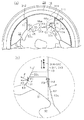
図1〜図3を参照して本発明の第1の実施形態について説明する。図1(a)(b)に示すように、車両用シートリクライニング装置1は、第1アームとしての円盤状のロアアーム10と、第2アームとしての円盤状のアッパアーム20とを備えている。ロアアーム10は、車両用シートの着座部を構成するシートクッション側に固定され、アッパアーム20は、車両用シートの背もたれ部を構成するシートバック側に固定される。
(First embodiment)
A first embodiment of the present invention will be described with reference to FIGS. As shown in FIGS. 1A and 1B, the vehicle seat reclining device 1 includes a disk-shaped
ロアアーム10は、例えば金属板の半抜き(ハーフブランキング)により成形されたもので、アッパアーム20側に開口する円形の凹部11を有している。凹部11は、ロアアーム10及びアッパアーム20の回転軸O1(軸線)を中心とする内周面11aを有している。
The
図2に併せ示すように、ロアアーム10の凹部11内には、3つの略扇状の凸部12が円周上に等角度間隔に配置されている。各凸部12は、その周方向両側にガイド壁13,14を形成する。各隣り合う凸部12の周方向で対向するガイド壁13,14同士は、回転軸O1を中心とする径方向に互いに平行に延びており、凹部11の底面と協働して回転軸O1を中心とする径方向に延びる略U字溝状のガイド溝15を円周上に等角度間隔に形成する。これらガイド溝15は、中央部で連通しており、全体として略Y字形状を呈している。なお、各凸部12の片側(図2において反時計回転方向に向かう側)のガイド壁13の径方向内側の部位には、径方向内側に向かうに従い周方向で対向するガイド壁14から当該方向に離隔するように傾斜する傾斜面13aが形成されている。
As shown in FIG. 2, three substantially fan-shaped
また、ロアアーム10の3つのガイド溝15が連通する中央部には、略円形の貫通孔16が形成されている。この貫通孔16は、所定角度位置で径方向外側に凹設された係止孔16aを有する。
In addition, a substantially circular through
アッパアーム20は、例えば金属板の半抜き(ハーフブランキング)により成形されたもので、ロアアーム10の内周面11aの内径と同等の外径の外周面20aを有するとともに、図1(b)に示すように、ロアアーム10側に開口する円形の凹部21を有している。凹部21は、回転軸O1を中心とする内周面21aを有している。凹部21の内周面21aには、内歯22が全周に亘って形成されている。また、凹部21の内周側には、該凹部21と同心円上に円形の凹部23が形成されている。凹部23の内周面23aには、図1(a)に示すように、回転軸O1に向かって突出する略円弧状の突部24が円周上に等角度間隔で2個所形成されている。
The
図1(b)に示すように、アッパアーム20は、その外周面20aで、ロアアーム10の内周面11aと摺接するように嵌合されている。そして、ロアアーム10及びアッパアーム20の外周部には、ロアアーム10の内周面11aとアッパアーム20の外周面20aとが嵌合された状態で、金属板からなるリング状のホルダ29が装着されている。ロアアーム10及びアッパアーム20は、このホルダ29によって相対回動が許容された状態で軸方向に抜け止めされている。
As shown in FIG. 1B, the
ロアアーム10とアッパアーム20との間には、ロック機構30が配設されている。このロック機構30は、図2に併せ示すように、主として、第1ポール31A、第2ポール31B及び第3ポール31Cと、カム32と、レリーズプレート33と、付勢部材としての渦巻きばね34と、3つの押圧部材60とによって構成されている。なお、請求項における「カム」は、カム32及びレリーズプレート33を含む構造体である。
A
第1〜第3ポール31A〜31Cは、隣り合う2つのガイド壁13,14の間に装着されて、回転軸O1を中心とする円周上に等角度間隔に配置されている。
第1ポール31Aは、鋼材を鍛造加工するなどして作製され、互いに段違い形成された第1ブロック41と第2ブロック42とを備えている。第1ポール31Aは、第1ブロック41がアッパアーム20の内周面21a側に配置され、第2ブロック42がアッパアーム20の軸心側に配置されている。これら第1ブロック41及び第2ブロック42の両幅端部311,312は一致するとともに、平行な直線となるように形成されている。第1ブロック41の円弧状の外方端(アッパアーム20の内歯22と対向する端面)には、アッパアーム20の内歯22と噛合可能な外歯44が形成され、第1ブロック41の内方端(外方端とは逆向きの端面である背面)には、カム32の外周部に係合する内面カム部45が形成されている。さらに、第2ブロック42には、板厚方向に貫通するポール側溝カム部46が幅方向の略中央部位に透設されている。
The first to third poles 31 </ b> A to 31 </ b> C are mounted between two
The first pole 31 </ b> A includes a
そして、第1ポール31Aは、その両幅端部311,312を両ガイド壁13,14に摺接する態様で回転軸O1を中心とする径方向への移動が案内されている。第1ポール31Aは、両ガイド壁13,14に沿って径方向に進退することで、その外歯44と内歯22とを噛合又は解除(係脱)する。
The
一方、第2及び第3ポール31B,31Cは、板状の鋼板をプレス加工するなどして作製され、第1ポール31Aの第2ブロック42が切除され、第1ブロック41のみによって構成された形状に近似した段差をもたない平板形状をなしている。すなわち、第2及び第3ポール31B,31Cは、第1ポール31Aに対して第2ブロック42の分だけ径方向に短く、かつ板厚も第2ブロック42の板厚分だけ薄く形成されている。第2及び第3ポール31B,31Cは、第1ポール31Aと同様に、両幅端部313,314は平行な直線に形成されている。第2及び第3ポール31B,31Cの円弧状の外方端には、アッパアーム20の内歯22と噛合可能な外歯47が形成され、第2及び第3ポール31B,31Cの内方端には、カム32の外周部に係合する内面カム部48が形成されている。さらに、第2及び第3ポール31B,31Cには、幅方向の中央部に係合突起49が突設されている。
On the other hand, the second and
そして、第2及び第3ポール31B,31Cは、各々の両幅端部313,314を両ガイド壁13,14に摺接する態様で回転軸O1を中心とする径方向への移動が案内されている。第2及び第3ポール31B,31Cは、両ガイド壁13,14に沿って径方向に進退することで、各々の外歯47と内歯22とを噛合又は解除(係脱)する。
The second and
ここで、第1ポール31Aの段差部に形成された内面カム部45は、図3(a)に拡大して示すように、第1ポール31Aの周方向の中央部と周方向の両側に、3つのポール側カム面50a,50b,50cを備えている。これらポール側カム面50a,50b,50cは、カム32の外周部(カム面55)に対向している。第1ポール31Aの中央部に設けられたポール側カム面50a及びカム32のロック回転方向の奥側に設けられたポール側カム面50bは、カム32のロック回転方向(図3の反時計回転方向)への回転に伴い該カム32の外周部に接近する傾斜面を有するカム面で構成されている。一方、カム32のロック回転方向の手前側に設けられたポール側カム面50cは、周方向で対向するガイド壁13(傾斜面13a)との間で楔状の空間を形成するように成形されており、径方向内側に向かうに従い周方向で対向するガイド壁13から当該方向に離隔するように傾斜するポール傾斜面51を有する。すなわち、ガイド壁13の傾斜面13aとポール傾斜面51との間隔は、径方向外方へ向かうに従って狭くなるように成形されている。
Here, the inner
なお、第2及び第3ポール31B,31Cの内方端に形成された内面カム部48も、第1ポール31Aの内面カム部45と同一形状に成形されている。
カム32は、アッパアーム20の凹部21内となる第1〜第3ポール31A〜31Cの内周側で、回転軸O1上に回転可能に配置されている。
The inner
The
カム32は、板状の鋼板をプレス加工するなどして作製され、段差をもたない平板形状をなしている。このカム32は、その外周部に円周上に等角度間隔に3組のカム面55を有している。各カム面55は、その周方向の中央部と周方向の両側に、3つの押圧カム部55a,55b,55cを備えている。
The
これらのうちの2つの押圧カム部55a,55bは、該当の第1〜第3ポール31A〜31Cの対向する2つのポール側カム面50a,50bに当接可能であり、カム32がロック位置に回転されたときに該当のポール側カム面50a,50bを押圧する。一方、これらのうちの残りの1つの押圧カム部55cは、該当の第1〜第3ポール31A〜31Cのポール側カム面50c及びガイド壁13(傾斜面13a)との間に形成される前述の楔状の空間内に、板材からなる楔状の押圧部材60を収容する。各押圧部材60は、ロアアーム10の凹部11と第1ポール31Aの第2ブロック42及びレリーズプレート33の周縁部とにより軸線方向に挟まれており、ポール側カム面50c(ポール傾斜面51)及びガイド壁13(傾斜面13a)に摺接しつつ径方向に移動できるようになっている。押圧カム部55cは、押圧部材60の内方端の端面である背面61に当接可能であり、カム32がロック位置に回転されたときに押圧部材60の背面61を押圧する。
Of these, the two
つまり、押圧カム部55a〜55cは、カム32がロック位置に回転されたときに、該当の第1〜第3ポール31A〜31Cのポール側カム面50a,50b及び押圧部材60の背面61にそれぞれ当接(圧接)する角度位置に保持されている。
That is, when the
押圧部材60は、ガイド壁13の傾斜面13a及びポール側カム面50cのポール傾斜面51のなす角度と同等の角度をなす押圧面62,63を有しており、カム32により背面61が押圧されることで、押圧面62,63において傾斜面13a及びポール傾斜面51にそれぞれ圧接する。
The pressing
このとき、図3(b)に更に拡大して示すように、押圧部材60の第1〜第3ポール31A〜31Cに対する押圧力Fは、実質的に第1〜第3ポール31A〜31Cの押圧点Pにおける接線Tの直交方向、即ち押圧点Pにおける法線方向に向かっている。従って、押圧部材60の押圧力Fは、第1〜第3ポール31A〜31Cの移動方向成分(径方向成分)の分力F1及び該移動方向に直交する方向であるポールの幅方向成分(周方向成分)の分力F2に分解される。そして、この分力F2での押圧による楔作用によって、第1〜第3ポール31A〜31Cの幅端部311,313とガイド壁13とが互いに離間する周方向の力を発生し、第1〜第3ポール31A〜31Cの幅端部312,314とガイド壁14との隙間が埋まる。
At this time, as further enlarged in FIG. 3B, the pressing force F of the pressing
一方、図3(a)に示すように、カム32がロックを解除する方向に回転されると、押圧カム部55a,55bは、該当の第1〜第3ポール31A〜31Cのポール側カム面50a,50bから離隔されるとともに、押圧カム部55cは、該当の押圧部材60の背面61から離隔される。
On the other hand, as shown in FIG. 3A, when the
このとき、押圧部材60は、該当の第1〜第3ポール31A〜31Cのポール側カム面50cとの間の摩擦力及び片側のガイド壁13の傾斜面13aとの間の摩擦力によってその解除が阻害される。しかしながら、図3(b)に示すように、押圧部材60とガイド壁13の傾斜面13aとの間の摩擦力F3は、例えば該当の第1〜第3ポール31A〜31Cの移動方向に沿う従来のガイド壁との間の摩擦力に比べて、押圧部材60の解除を阻害する当該第1〜第3ポール31A〜31Cの移動方向成分(径方向成分)の分力F4が傾斜面13aの傾斜分だけ低減される。これにより、押圧部材60及び該当の第1〜第3ポール31A〜31Cのポール側カム面50cの食い付きが抑えられる。
At this time, the pressing
カム32の側面には、円周上に間隔をおいて複数の係合突起57が突設され、これら係合突起57の1つが、第1ポール31Aのポール側溝カム部46に挿入・係合されている。ポール側溝カム部46及び係合突起57は、カム32のロック解除回転方向への回転によって第1ポール31Aを径方向内方へ移動させるように作用する。
A plurality of
カム32の側面には、薄板状のレリーズプレート33が係合突起57に係合されて一体的に取付けられている。このレリーズプレート33は、中心部に貫通孔33aを有している。レリーズプレート33は、第1ポール31Aの第2ブロック42と軸線方向に一致するようにカム32に取付けられており、第2ポール31Bの端面に摺接可能に対接されている。これによって、第2及び第3ポール31B,31C及びレリーズプレート33が第1ポール31Aの厚みの範囲内に収められている。レリーズプレート33は、アッパアーム20に形成した突部24とは非接触状態となる略円環形のプレートからなり、その円環形のプレートの一部位に扇型の切欠き33bが形成され、この切欠き33bの部位に第1ポール31Aが配設されている。すなわち、その円環形のプレートを第1ポール31Aに対応する角度範囲だけ扇型に切欠くことにより、カム32の回転によってレリーズプレート33が第1ポール31Aに干渉しないようにしている。
On the side surface of the
レリーズプレート33の回転中心を中心とする円周上には、板厚方向に貫通して2つのレリーズプレート側溝カム部59が形成されている。これらレリーズプレート側溝カム部59は、第2及び第3ポール31B,31Cの端面にそれぞれ対応するように、係合突起57の円周位置よりも径方向外方に配置されている。レリーズプレート側溝カム部59には、第2及び第3ポール31B,31Cに突設された係合突起49がそれぞれ挿入・係合されている。レリーズプレート側溝カム部59と係合突起49との係合によって、カム32とともにレリーズプレート33がロックを解除する方向(図1(a)の時計回転方向)に回転されると、第2及び第3ポール31B,31Cを径方向内方へ移動させるようにしている。
Two release plate side
渦巻きばね34は、第1〜第3ポール31A〜31Cをアッパアーム20に係合する方向にカム32を回転付勢するもので、ロアアーム10の貫通孔16内に収納されている。渦巻きばね34は、図2に示すように、例えば略矩形の扁平な線材を所定の渦巻き形状に曲成することにより形成されており、ロアアーム10とカム32との間に配設されている。すなわち、渦巻きばね34の外端部34aは、係止孔16aに係止され、内端部34bは、カム32の端面に設けた図略の係止部に係止されている。
The
かかる渦巻きばね34の付勢力によって、カム32はロアアーム10に対してロック回転方向(図1(a)の反時計回転方向)に回転付勢され、そのカム面55によって第1〜第3ポール31A〜31Cを径方向外方に押圧し、各々の外歯44,47をアッパアーム20の内歯22に係合させるようになっている。
Due to the biasing force of the
次に、本実施形態の動作について説明する。
図1(a)に示すように、車両用シートリクライニング装置1のロック状態においては、渦巻きばね34によりカム32が図示反時計回転方向に回転付勢されることで、該カム32の押圧カム部55a,55bと第1〜第3ポール31A〜31Cの内面カム部45,48のポール側カム面50a,50bがそれぞれ当接する。また、カム32の押圧カム部55cと第1〜第3ポール31A〜31Cの内面カム部45,48のポール側カム面50cが押圧部材60を介してそれぞれ当接する。そして、第1〜第3ポール31A〜31Cが径方向外方へ押圧されている。これにより、第1〜第3ポール31A〜31Cの外歯44,47とアッパアーム20の内歯22とが噛合い、ロアアーム10に対するアッパアーム20の回動が規制されて、シートクッションに対するシートバックの回動が規制(ロック)される。
Next, the operation of this embodiment will be described.
As shown in FIG. 1A, in the locked state of the vehicle seat reclining device 1, the
この際、押圧カム部55cは、該当の第1〜第3ポール31A〜31Cのポール側カム面50c及びガイド壁13(傾斜面13a)との間に収容される押圧部材60の背面61を押圧することで、楔作用によって第1〜第3ポール31A〜31Cの幅端部311,313とガイド壁13とが互いに離間する周方向の力を発生する。これにより、ガイド壁13を設けたロアアーム10と第1〜第3ポール31A〜31Cの係合されたアッパアーム20とが僅かに相対回転しながら、第1〜第3ポール31A〜31Cの幅端部312,314が反対側のガイド壁14に押し付けられてそれらの間の隙間がそれぞれ除去される。その結果、シートクッションに対するシートバックのがたつきを防止することが可能となる。
At this time, the
この状態で、操作ハンドルを操作してカム32及びレリーズプレート33を渦巻きばね34の付勢力に抗して一体的に回転させると、カム32の押圧カム部55a,55bと第1〜第3ポール31A〜31Cの内面カム部45,48のポール側カム面50a,50bとの当接がそれぞれ外れる。また、カム32の押圧カム部55cと第1〜第3ポール31A〜31Cの内面カム部45,48のポール側カム面50cとの押圧部材60を介した当接がそれぞれ外れる。そして、第1ポール31Aのポール側溝カム部46とカム32の係合突起57との係合作用によって、第1ポール31Aがガイド壁13,14に沿って回転軸O1側に引き寄せられ、第1ポール31Aの外歯44と内歯22との噛合を解除しようとする。同時に、第2及び第3ポール31B,31Cの係合突起49とレリーズプレート側溝カム部59との係合作用によって、第2及び第3ポール31B,31Cがガイド壁13,14に沿って回転軸O1側に引き寄せられ、第2及び第3ポール31B,31Cの外歯47と内歯22との噛合を解除しようとする。
In this state, when the operating handle is operated to rotate the
このとき、押圧部材60の解除を阻害するガイド壁13の傾斜面13aとの間の摩擦力は、前述の態様で低減されている。これにより、カム32による押圧から解放される押圧部材60が該当の第1〜第3ポール31A〜31Cのポール側カム面50c(ポール傾斜面51)及びガイド壁13(傾斜面13a)に食い付くことなく円滑に解除される。そして、押圧部材60によるポール側カム面50cの押圧の解放された第1〜第3ポール31A〜31Cの回転軸O1側への移動(両ガイド壁13,14に沿う退行)が許容される。そして、第1〜第3ポール31A〜31Cの外歯44,47及び内歯22が円滑に解除され、ロアアーム10に対するアッパアーム20の回動が許容されて、シートクッションに対するシートバックの回動が許容(アンロック)される。従って、シートクッションに対してシートバックを任意の角度位置に回動させることが可能となる。
At this time, the frictional force with the
また、ロックを解除した状態で、シートバックをシートクッションに対して、所定の角度以上前方に、いわゆる前倒し角度範囲に回転させると、アッパアーム20の凹部23の内周面23aに形成された突部24は、第1ポール31Aに形成された係合部43と内歯22との間に位置される。すなわち、第1ポール31Aは、その係合部43がアッパアーム20の突部24に係合することによって、径方向外方への移動が妨げられるようになる。この状態で、操作ハンドルの操作力を解放すると、渦巻きばね34に付勢されるカム32が、第1ポール31Aを内歯22の噛み合う方向に押し付けんとするが、アッパアーム20の突部24と第1ポール31Aの係合部43との係合によって、第1ポール31Aの移動は阻止されるため、噛み合いは生じない。同時に、第1ポール31Aの径方向移動が阻止されることによって、カム32の回転も阻止されるため、レリーズプレート33が回転せず、レリーズプレート側溝カム部59によって、第2及び第3ポール31B,31Cも内歯22から離隔した非噛合位置に保持される。従って、前倒し角度範囲では、シートバックはロックされずに自由に回転させることができる。
Further, when the seat back is rotated forward by a predetermined angle or more with respect to the seat cushion in a so-called forward angle range with the lock released, a protrusion formed on the inner
前倒し状態から再び、操作レバーを操作して、シートバックを着座に最適な位置になるように後方に戻し、その位置で操作ハンドルの操作力を解放すると、第1〜第3ポール31A〜31C、カム32及びレリーズプレート33が、図1(a)に示す状態に復帰し、ロック状態となる。
When the operating lever is operated again from the forward-turned state to return the seat back to the optimum position for seating and the operating force of the operating handle is released at that position, the first to
以上詳述したように、本実施形態によれば、以下に示す効果が得られるようになる。
(1)本実施形態では、渦巻きばね34の付勢力に抗してカム32を回転させると、該カム32が第1〜第3ポール31A〜31Cに係合することで、該第1〜第3ポール31A〜31Cは両ガイド壁13,14に沿って退行して外歯44,47及び内歯22を解除しようとする。このとき、押圧部材60は、第1〜第3ポール31A〜31Cのポール側カム面50cとの間の摩擦力及びガイド壁13の傾斜面13aとの間の摩擦力によってその解除が阻害される。しかしながら、押圧部材60とガイド壁13の傾斜面13aとの間の摩擦力は、例えば第1〜第3ポール31A〜31Cの移動方向に沿うガイド壁との間の摩擦力に比べて、押圧部材60の解除を阻害する第1〜第3ポール31A〜31Cの移動方向成分(径方向成分)の分力が傾斜面13aの傾斜分だけ低減される。これにより、カム32による押圧から解放される押圧部材60が第1〜第3ポール31A〜31Cのポール側カム面50c等に食い付くことなく円滑に解除されて、押圧部材60によるポール側カム面50cの押圧の解放された第1〜第3ポール31A〜31Cのガイド壁13,14に沿う退行が許容される。そして、外歯44,47及び内歯22も円滑に解除され、ロアアーム10及びアッパアーム20の相対回動が許容されて、シートクッションに対するシートバックの回動が許容(アンロック)される。
As described above in detail, according to the present embodiment, the following effects can be obtained.
(1) In the present embodiment, when the
以上により、外歯44,47及び内歯22の噛合状態において該内歯22からの外力に対する保持力として機能する押圧部材60の押圧力における第1〜第3ポール31A〜31Cの幅方向成分(周方向成分)の分力を好適に確保しながらも、押圧部材60と共に外歯44,47及び内歯22を円滑に解除できる。
As described above, the components in the width direction of the first to third poles 31 </ b> A to 31 </ b> C in the pressing force of the pressing
(第2の実施形態)
図4〜図6を参照して本発明の第2の実施形態について説明する。なお、第2の実施形態は、主に前記第1の実施形態のポール及びカムの係合構造を変更したものであるため、同様の構成については同一の符号を付してその説明を一部省略する。
(Second Embodiment)
A second embodiment of the present invention will be described with reference to FIGS. In the second embodiment, the pole and cam engagement structure of the first embodiment is mainly changed. Therefore, the same components are denoted by the same reference numerals, and a part of the description is given. Omitted.
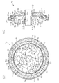
図4(a)(b)に示すように、本実施形態の車両用シートリクライニング装置70は、第1アームとしての円盤状のロアアーム71と、第2アームとしての円盤状のアッパアーム76とを備えている。なお、ロアアーム71及びアッパアーム76の回転軸O1に沿う中央部には、互いに同等の内径の円形の貫通孔71a,76aがそれぞれ形成されている。
As shown in FIGS. 4A and 4B, the vehicle
図5に併せ示すように、ロアアーム71の凹部11内には、3つの略扇状の凸部72が円周上に等角度間隔に配置されている。各凸部72は、その周方向両側にガイド壁73,74を形成する。各隣り合う凸部72の周方向で対向するガイド壁73,74同士は、回転軸O1を中心とする径方向に互いに平行に延びており、凹部11の底面と協働して回転軸O1を中心とする径方向に延びる略U字溝状のガイド溝75を円周上に等角度間隔に形成する。これらガイド溝75は、中央部で連通しており、全体として略Y字形状を呈している。なお、各凸部72の片側(図5において時計回転方向に向かう側)のガイド壁74の径方向内側の部位には、径方向内側に向かうに従い周方向で対向するガイド壁73から当該方向に離隔するように傾斜する傾斜面74aが形成されている。
As shown in FIG. 5, in the
ロアアーム71とアッパアーム76との間には、3つのポール80と、カム90とが収容されている。3つのポール80は、回転軸O1と直交する面内に円周上に等角度間隔に配置されている。
Between the
すなわち、各ポール80は、板状の鋼板をプレス加工するなどして作製され、基本的に段差をもたない略門形の平板形状をなしている。そして、各ポール80は、その両幅端部81が平行な直線となるように形成されている。各ポール80は、その両幅端部81をガイド溝75の両ガイド壁73,74に摺接させる態様でガイド溝75に沿って径方向に移動自在に装着されている。
That is, each
各ポール80は、その円弧状の外方端(アッパアーム76の内歯22と対向する端面)に内歯22と噛合可能な外歯82が形成されている。従って、各ポール80は、両ガイド壁73,74に沿って径方向に進退することで、その外歯82と内歯22とを噛合又は解除(係脱)する。
Each
また、各ポール80は、図6(a)に拡大して示すように、その内方端(外方端とは逆向きの端面)に、カム90の外周部に係合する内面カム部83が形成されている。この内面カム部83は、図6(a)においてポール80の時計回転方向及び反時計回転方向に向かう側に配設された一対のポール側カム面83a,83b及び両ポール側カム面83a,83bのなす門形の内側に配置された掛部83cによって形成されている。カム90のロック回転方向の奥側に設けられたポール側カム面83bは、周方向で対向するガイド壁74(傾斜面74a)との間で楔状の空間を形成するように成形されており、径方向内側に向かうに従い周方向で対向するガイド壁74から当該方向に離隔するように傾斜するポール傾斜面84を有する。すなわち、ガイド壁74の傾斜面74aとポール傾斜面84との間隔は、径方向外方へ向かうに従って狭くなるように成形されている。なお、各ポール80には、凹部23(内周面23a)に径方向で対向するように、アッパアーム76に向かう軸線方向に円弧状の係合部85が突設されている。
Further, as shown in an enlarged view in FIG. 6A, each
カム90は、板状の鋼板をプレス加工するなどして作製され、段差をもたない平板形状をなしている。このカム90は、ロアアーム71のガイド溝75及びアッパアーム76の凹部21(内歯22)の形成された軸線方向の範囲(即ちポール80の配置される軸線方向の範囲)で回転軸O1上に回転可能に配置されている。なお、カム90の中央部には、図4に示すように、略小判形のカム嵌合孔94が形成されている。
The
カム90は、その外周部に円周上に等角度間隔に3組のカム面91を有している。各カム面91は、図6(a)においてカム90の時計回転方向及び反時計回転方向に向かう側に配設された略三角形状の肩部93及びフック92によって形成されている。
The
肩部93は、該当のポール80の対向するポール側カム面83aに当接可能であり、カム90がロック位置に回転されたときに該当のポール側カム面83aを押圧する。一方、フック92は、該当のポール80のポール側カム面83b及びガイド壁74(傾斜面74a)との間に形成される前述の楔状の空間内に、板材からなる楔状の押圧部材100を収容する。各押圧部材100は、ポール側カム面83b(ポール傾斜面84)及びガイド壁74(傾斜面74a)に摺接しつつ径方向に移動できるようになっている。フック92は、押圧部材100の内方端の端面である背面101に当接可能であり、カム90がロック位置に回転されたときに押圧部材100の背面101を押圧する。
The
つまり、肩部93及びフック92は、カム90がロック位置に回転されたときに、該当のポール80のポール側カム面83a及び押圧部材100の背面101にそれぞれ当接(圧接)する角度位置に保持されている。
In other words, the
押圧部材100は、ガイド壁74の傾斜面74a及びポール側カム面83bのポール傾斜面84のなす角度と同等の角度をなす押圧面102,103を有しており、カム90により背面101が押圧されることで、押圧面102,103において傾斜面74a及びポール傾斜面84にそれぞれ圧接する。
The pressing
ここで、カム90は、図示反時計回転方向への回転に伴い、各フック92及び各肩部93で各押圧部材100の背面101及び各ポール80のポール側カム面83aをそれぞれ押圧することで、該ポール80をロアアーム71のガイド溝75に沿って径方向外側に押し出す。従って、全てのポール80の係合部85がアッパアーム76のいずれかの突部24に径方向で対向していなければ、ポール80の外歯82がアッパアーム76の内歯22に噛合する。
Here, as the
このとき、図6(b)に更に拡大して示すように、押圧部材100のポール80に対する押圧力F10は、実質的にポール80の押圧点P10における接線T10の直交方向、即ち押圧点P10における法線方向に向かっている。従って、押圧部材100の押圧力F10は、ポール80の移動方向成分(径方向成分)の分力F11及び該移動方向に直交する方向であるポールの幅方向成分(周方向成分)の分力F12に分解される。そして、この分力F12での押圧による楔作用によって、ポール80の幅端部81とガイド壁74とが互いに離間する周方向の力を発生し、ポール80の反対側の幅端部81とガイド壁73との隙間が埋まる。
At this time, as further enlarged and shown in FIG. 6B, the pressing force F10 of the
なお、ポール80がロアアーム10のガイド溝75に沿って径方向外側に押し出された際、いずれかのポール80の係合部85がアッパアーム76のいずれかの突部24に径方向で対向すれば、ポール80の径方向外側への移動が係止されるとともにカム90が回り止めされて、ポール80の外歯82がアッパアーム76の内歯22に噛合不能となる。
When the
一方、カム90は、図6(a)に示すように、図示時計回転方向への回転に伴い、各フック92で各ポール80の掛部83cを引っ掛けることで、ポール80をロアアーム71のガイド溝75に沿って径方向内側に引き込む。これにより、ポール80の外歯82は、アッパアーム76の内歯22との噛合状態を解除しようとする。同時に、肩部93は、該当のポール80のポール側カム面83aから離隔されるとともに、フック92は、該当の押圧部材100の背面101から離隔される。
On the other hand, as shown in FIG. 6A, the
このとき、押圧部材100は、該当のポール80のポール側カム面83bとの間の摩擦力及び片側のガイド壁74の傾斜面74aとの間の摩擦力によってその解除が阻害される。しかしながら、図6(b)に示すように、押圧部材100とガイド壁74の傾斜面74aとの間の摩擦力F13は、例えば該当のポール80の移動方向に沿う従来のガイド壁との間の摩擦力に比べて、押圧部材100の解除を阻害する当該ポール80移動方向成分(径方向成分)の分力F14が傾斜面74aの傾斜分だけ低減される。これにより、押圧部材100及び該当のポール80のポール側カム面83bの食い付きが抑えられる。
At this time, the release of the
カム90のカム嵌合孔94には、ヒンジカム110が嵌挿されている。すなわち、ヒンジカム110は、回転軸O1に沿って延びる軸線を有している。ヒンジカム110は、ロアアーム71(貫通孔71a)を貫通して該ロアアーム71に回転自在に支持される第1軸部111、アッパアーム76(貫通孔76a)を貫通して該アッパアーム76に軸支される第2軸部112、及び係合部85の内周側で凹部23の形成する空間S1に収容されるフランジ部113を有する。第1軸部111は、略小判形の外壁面を有しており、ヒンジカム110は、第1軸部111においてカム90のカム嵌合孔94に嵌合する。これにより、カム90は、ヒンジカム110と一体回転するように連結される。一方、第2軸部112は、貫通孔76aの内径と同等の外径の外周面を有しており、該貫通孔76aに摺接する。そして、フランジ部113は、係合部85の内周側で凹部23の形成する空間S1に収容されることで、ロアアーム71のガイド溝75との間で全てのポール80及びカム90を軸線方向で規制する。
A
ヒンジカム110の第1軸部111には、図5に示すように、ロアアーム71に外周側の脚部120aが係止された付勢部材としての渦巻きばね120の内周側の脚部120bが係止されている。この渦巻きばね120は、ヒンジカム110を一方向に回転付勢することで、カム90を介してポール80を外歯82及び内歯22が噛合又は係合部85及び突部24が当接する径方向に移動させる。
As shown in FIG. 5, the
なお、ヒンジカム110は、操作部材(図示略)から解除操作力が入力されることで、渦巻きばね120の付勢力に抗して逆方向に回転する。このとき、ヒンジカム110は、カム90を介してポール80を外歯82及び内歯22が解除する径方向に移動させる。
The
次に、本実施形態の動作について説明する。
図4(a)に示すように、車両用シートリクライニング装置70のロック状態においては、渦巻きばね120によりカム90が図示反時計回転方向に回転付勢されることで、該カム90の肩部93とポール80の内面カム部83のポール側カム面83bが当接するとともに、カム90のフック92とポール80の内面カム部83のポール側カム面83aが押圧部材100を介して当接し、ポール80が径方向外方へ押圧されている。これにより、ポール80の外歯82とアッパアーム76の内歯22とが噛合い、ロアアーム71に対するアッパアーム76の回動が規制されて、シートクッションに対するシートバックの回動が規制(ロック)される。
Next, the operation of this embodiment will be described.
As shown in FIG. 4A, in the locked state of the vehicle
この際、フック92は、該当のポール80のポール側カム面83a及びガイド壁74(傾斜面74a)との間に収容される押圧部材100の背面101を押圧することで、楔作用によってポール80の幅端部81とガイド壁74とが互いに離間する周方向の力を発生する。これにより、ガイド壁74を設けたロアアーム71とポール80の係合されたアッパアーム76とが僅かに相対回転しながら、ポール80の幅端部81が反対側のガイド壁73に押し付けられてそれらの間の隙間がそれぞれ除去される。その結果、シートクッションに対するシートバックのがたつきを防止することが可能となる。
At this time, the
この状態で、操作ハンドルを操作してヒンジカム110及びカム90を渦巻きばね120の付勢力に抗して一体的に回転させると、カム90の肩部93とポール80の内面カム部83のポール側カム面83bとの当接がそれぞれ外れるとともに、カム90のフック92とポール80の内面カム部83のポール側カム面83aとの押圧部材100を介した当接がそれぞれ外れる。そして、ポール80の掛部83cとカム90のフック92との係合作用によって、ポール80がガイド壁73,74に沿って回転軸O1側に引き寄せられ、ポール80の外歯82と内歯22との噛合を解除しようとする。
In this state, when the operating handle is operated to integrally rotate the
このとき、押圧部材100の解除を阻害するガイド壁74の傾斜面74aとの間の摩擦力は、前述の態様で低減されている。これにより、カム90による押圧から解放される押圧部材100が該当のポール80のポール側カム面83a(ポール傾斜面84)及びガイド壁74(傾斜面74a)に食い付くことなく円滑に解除されて、押圧部材100によるポール側カム面83aの押圧の解放されたポール80の回転軸O1側への移動(両ガイド壁73,74に沿う退行)が許容される。そして、ポール80の外歯82及び内歯22が円滑に解除され、ロアアーム71に対するアッパアーム76の回動が許容されて、シートクッションに対するシートバックの回動が許容(アンロック)される。従って、シートクッションに対してシートバックを任意の角度位置に回動させることが可能となる。
At this time, the frictional force with the
また、車両用シートリクライニング装置70のロックを解除した状態で、シートバックをシートクッションに対して、所定の角度以上前方に、いわゆる前倒し角度範囲に回転させると、アッパアーム76の凹部23の内周面23aに形成された突部24は、ポール80に形成された係合部85と径方向で対向する。従って、ポール80は、その係合部85がアッパアーム76の突部24に係合することによって、径方向外方への移動が妨げられるようになる。この状態で、操作部材の解除操作力を解放すると、渦巻きばね120によりカム90が図示反時計回転方向に回転付勢されることで、該カム90の肩部93がポール80のポール側カム面83bを押圧するとともに、フック92が押圧部材100の背面101を押圧する。しかしながら、アッパアーム76の突部24とポール80の係合部85との係合によって、ポール80の移動は阻止されるため、噛み合いは生じない。従って、前倒し角度範囲では、シートバックはロックされずに自由に回転させることができる。
Further, when the seat back is rotated forward by a predetermined angle or more with respect to the seat cushion in a so-called forward angle range with the vehicle
前倒し状態から再び、操作部材への解除操作力の入力により、シートバックを着座に最適な位置になるように後方に戻し、その位置で操作部材の解除操作力を解放すると、ポール80及びカム90が、図4(a)に示す状態に復帰し、ロック状態となる。
When the seat back is returned to the optimal position for seating by inputting the release operation force to the operation member again from the forward-turned state, and the release operation force of the operation member is released at that position, the
特に、ヒンジカム110のフランジ部113は、係合部85の内周側で凹部23の形成する空間S1に収容されることで、全てのポール80及びカム90を軸線方向で規制する。これにより、これらポール80及びカム90が軸線方向で安定的に姿勢保持される。また、ヒンジカム110は、第1軸部111で渦巻きばね120に回転付勢されることでその軸線を傾斜しようとしても、第1軸部111及び第2軸部112においてロアアーム71及びアッパアーム76により両持ちで支持されることで、当該傾斜が抑制される。
In particular, the
以上詳述したように、本実施形態によれば、前記第1の実施形態と同様の効果が得られるようになる。
なお、上記実施形態は以下のように変更してもよい。
As described above in detail, according to the present embodiment, the same effect as in the first embodiment can be obtained.
In addition, you may change the said embodiment as follows.
・前記第1の実施形態において、押圧部材60は、第1〜第3ポール31A〜31Cのうちの少なくとも一つに対応して設ければよい。
・前記第1の実施形態において、係合部43は、第1〜第3ポール31A〜31Cのうちの少なくとも一つに設ければよい。
In the first embodiment, the pressing
In the first embodiment, the engaging
・前記第2の実施形態において、押圧部材100は、3つのポール80のうちの少なくとも一つに対応して設ければよい。
・前記第2の実施形態において、係合部85は、3つのポール80のうちの少なくとも一つに設ければよい。
In the second embodiment, the pressing
In the second embodiment, the engaging
・前記各実施形態において、各ポールに対し押圧部材を2個ずつ配設してもよい。
・前記各実施形態において、傾斜面13a,74a等に圧接する押圧部材の形状は、例えば円柱状や球体状であってもよい。
-In each said embodiment, you may arrange | position two press members with respect to each pole.
In each embodiment described above, the shape of the pressing member that presses against the
・前記各実施形態において、アッパアーム20,76の突部24の個数は任意である。
・前記各実施形態において、ロアアーム10,71内に配設されるポールの個数は任意である。また、複数のポールが配設される場合、これらの動作が連動するのであれば互いに異なる形状であってもよいし、同一形状であってもよい。
In each embodiment described above, the number of the
In each of the above embodiments, the number of poles disposed in the
・前記実施形態において、シートクッション側及びシートバック側と、ロアアーム10,71及びアッパアーム20,76の固定関係は逆であってもよい。
In the above-described embodiment, the fixing relationship between the seat cushion side and the seat back side, and the
1,70…車両用シートリクライニング装置、10,71…ロアアーム(第1アーム)、13,14,73,74…ガイド壁、13a,74a…傾斜面、20,76…アッパアーム(第2アーム)、22…内歯、31A…第1ポール(ポール)、31B…第2ポール(ポール)、31C…第3ポール(ポール)、32…カム(カム)、33…レリーズプレート(カム)、311〜314,81…幅端部、34,120…渦巻きばね(付勢部材)、44,47,82…外歯、60,100…押圧部材、80…ポール、90…カム。
DESCRIPTION OF
Claims (4)
前記シートクッション及び前記シートバックの他方に固定される第2アームであって、該第2アームは、回転軸線の周りに回転可能に前記第1アームに支持され、前記回転軸線を中心とする径方向の内側へ向かって形成された複数の内歯を有する前記第2アームと、
前記第2アームの内歯に噛合可能であり、かつ径方向外側へ向かって形成された複数の外歯を有する少なくとも一つのポールであって、前記各ポールは、前記各対のガイド壁の間に配置されて、該ガイド壁によって径方向に沿った移動が案内される前記ポールと、
前記ポールに係合するとともに、前記回転軸線の周りに正方向および逆方向に選択的に回転可能なカムであって、前記カムが前記正方向に回転するとき、前記各ポールを径方向外側へ向かって移動させるように押圧して、前記各ポールの外歯を前記第2アームの内歯に噛合させ、前記カムが前記逆方向に回転するとき、前記各ポールを径方向内側へ向かって移動させて、前記各ポールの外歯を前記第2アームの内歯から離間させる前記カムと、
前記ガイド壁のうち少なくとも一つにおける径方向内側の部位に形成され、径方向内側が前記ポールから離間するように傾斜する少なくとも一つの傾斜面と、
前記傾斜面及び前記ポールの径方向内面の間に配置される少なくとも一つの押圧部材であって、前記カムが前記正方向へ回転するとき、該押圧部材は、前記カムによって径方向外側へ向かって押圧されて、前記ポールの径方向内面を押圧することにより、該傾斜面を有するガイド壁から前記ポールへの方向に前記ポールを押圧するとともに、前記ポールを径方向外側へ向かって移動させ、前記カムが前記逆方向へ回転するとき、前記押圧部材は、該カムによる押圧から解放されることで、前記ポールの径方向内面への押圧を解放して、該ポールが径方向内側へ向かって移動することを許容する前記押圧部材と、
前記カムを前記正方向に向けて付勢して、前記ポールを径方向外側へ向けて移動させる付勢部材とを備えたことを特徴とする車両用シートリクライニング装置。 Is fixed to either the seat cushion 及 beauty seatback, a first arm having opposing guide walls at least one pair,
A the seat cushion 及 beauty the second arm and the other to the Ru is fixed in the seat back, the second arm is supported lifting the rotatable first arm about a rotation axis, and about the axis of rotation The second arm having a plurality of internal teeth formed radially inward ,
Wherein the internal teeth of the second arm is engageable, and a least one of the pole that have a plurality of external teeth formed toward the radial direction outer side, wherein each pole, of each pair guide wall is disposed between, and the pole moves in the radial direction by the guide wall is guided,
A cam that engages with the pole and is selectively rotatable in a forward direction and a reverse direction around the rotation axis, and when the cam rotates in the forward direction, each of the poles is radially outward. The outer teeth of each pole are meshed with the inner teeth of the second arm, and when the cam rotates in the opposite direction, the poles move inward in the radial direction. The cam for separating the external teeth of each pole from the internal teeth of the second arm ;
At least one inclined surface at least one is formed at a portion of the radially inner side of, the radially inner inclined so as to be separated from the pole of the front Symbol guide wall,
And at least one of the pressing member that is disposed between the inclined surface and the radially inner surface of the pole, when the cam is rotated to the forward direction, the pressing member is toward therefore radially outward to said cam is pressed, by pressing the radial inner surface of the pole, while pressing the pawl in the direction to the pole from the guide wall having an inclined surface, it is moved towards the pole radially outward Te when said cam rotates to the reverse direction, the pressing member, by being freed from the pressing by the cam releases the pressure on the radial inner surface of the pole, the pole is radially inward It said pressing member permits to move towards it,
And urges the cam to the forward direction, the vehicle seat reclining apparatus is characterized in that a biasing member for moving toward the pole radially outward.
前記押圧部材は、前記ガイド壁の各対のうちのいずれか一方にのみ配置されていることを特徴とする車両用シートリクライニング装置。 The vehicle seat reclining device according to claim 1,
The pressing member, the guide wall seat reclining apparatus characterized by being arranged only on one of each pair of.
前記カムによって押圧される前記ポールの押圧部は、前記押圧部材を介して前記カムに押圧される前記ポールの径方向内面の一部分と、前記カムに直接に押圧される前記ポールの径方向内面の一つ又は二つの部分とからなり、各部分は前記ポールの径方向内面上において間隔をおいて配置されていることを特徴とする車両用シートリクライニング装置。 The vehicle seat reclining device according to claim 2,
Pressing part of the pole that will be pressed me by the cam includes a first portion of the radially inner surface of the pole that will be pressed against the cam via the pressing member, Ru is pressed directly to the cam the consists of a one or two parts of the radially inner surface of the pole, the vehicle seat reclining device each portion, characterized that you have been spaced on the radially inner surface of the pole.
前記シートクッション及び前記シートバックのいずれか一方に固定され、一対の相対向するガイド壁を有し、且つ円形状をなす第1アームと、 A first arm fixed to one of the seat cushion and the seat back, having a pair of opposing guide walls and having a circular shape;
前記シートクッション及び前記シートバックの他方に固定され、第1歯を有し、前記第1アームに回転自在に支持される第2アームと、 A second arm fixed to the other of the seat cushion and the seat back, having a first tooth and rotatably supported by the first arm;
前記第1歯に噛合可能な第2歯を有し、前記ガイド壁の間に配置されて、該ガイド壁によって、前記第1アームにおける径方向に沿った移動が案内されるポールと、 A pole having a second tooth meshable with the first tooth, disposed between the guide walls, and guided by the guide wall along a radial direction in the first arm;
前記第2アームに対して正方向および逆方向に選択的に回転可能に支持され、且つ前記ポールに係合するカムであって、前記カムが前記正方向に回転するとき、前記第1歯が前記第2歯に噛合するように前記ポールを前記径方向に沿って移動させ、前記カムが前記逆方向に回転するとき、前記第1歯が前記第2歯から離間するように前記ポールを前記径方向に沿って移動させる前記カムと、 A cam that is selectively rotatably supported in the forward direction and the reverse direction with respect to the second arm and that engages with the pole, and when the cam rotates in the forward direction, the first tooth is The pawl is moved along the radial direction so as to mesh with the second tooth, and when the cam rotates in the opposite direction, the pawl is moved away from the second tooth. The cam to be moved along the radial direction;
前記第1アームの径方向内側において前記ガイド壁の一方に形成され、かつ前記第1アームの径方向外側から前記第1アームの径方向内側に向かって前記ポールから離間するように傾斜する傾斜面と、 An inclined surface formed on one of the guide walls on the radially inner side of the first arm and inclined so as to be separated from the pole from the radially outer side of the first arm toward the radially inner side of the first arm. When,
前記傾斜面と前記ポールとの間に配置される押圧部材とを備え、 A pressing member disposed between the inclined surface and the pole;
前記カムが前記正方向に回転するとき、前記押圧部材が該カムに押圧されることにより前記ポールの面が押圧され、前記ポールは前記押圧部材の押圧により前記ガイド壁に押付けられつつ前記一対のガイド壁に沿って移動し、前記カムが前記逆方向に回転するとき、前記カムによる前記押圧部材への押圧が解放され、前記押圧部材による前記ポールの面への押圧が解放されて、前記一対のガイド壁に沿った径方向内側に向かう前記ポールの移動が許容されることを特徴とする車両用シートリクライニング装置。 When the cam rotates in the positive direction, the pressing member is pressed by the cam to press the surface of the pole, and the pole is pressed against the guide wall by the pressing member. When the cam moves along the guide wall and the cam rotates in the opposite direction, the pressure on the pressing member by the cam is released, and the pressure on the surface of the pole by the pressing member is released, and the pair A vehicle seat reclining device characterized in that the pole is allowed to move radially inward along the guide wall.
Priority Applications (3)
| Application Number | Priority Date | Filing Date | Title |
|---|---|---|---|
| JP2011132411A JP5434969B2 (en) | 2011-06-14 | 2011-06-14 | Vehicle seat reclining device |
| PCT/JP2012/064936 WO2012173098A1 (en) | 2011-06-14 | 2012-06-11 | Seat reclining device for vehicle |
| US14/124,916 US8955911B2 (en) | 2011-06-14 | 2012-06-11 | Seat reclining device for vehicle |
Applications Claiming Priority (1)
| Application Number | Priority Date | Filing Date | Title |
|---|---|---|---|
| JP2011132411A JP5434969B2 (en) | 2011-06-14 | 2011-06-14 | Vehicle seat reclining device |
Publications (3)
| Publication Number | Publication Date |
|---|---|
| JP2013000229A JP2013000229A (en) | 2013-01-07 |
| JP2013000229A5 JP2013000229A5 (en) | 2013-10-24 |
| JP5434969B2 true JP5434969B2 (en) | 2014-03-05 |
Family
ID=47357085
Family Applications (1)
| Application Number | Title | Priority Date | Filing Date |
|---|---|---|---|
| JP2011132411A Expired - Fee Related JP5434969B2 (en) | 2011-06-14 | 2011-06-14 | Vehicle seat reclining device |
Country Status (3)
| Country | Link |
|---|---|
| US (1) | US8955911B2 (en) |
| JP (1) | JP5434969B2 (en) |
| WO (1) | WO2012173098A1 (en) |
Families Citing this family (16)
| Publication number | Priority date | Publication date | Assignee | Title |
|---|---|---|---|---|
| KR101327956B1 (en) * | 2012-03-06 | 2013-11-13 | 현대다이모스(주) | Reclining device for vehicle seat |
| JP5969873B2 (en) * | 2012-09-27 | 2016-08-17 | 富士機工株式会社 | Vehicle seat reclining device |
| JP2015030318A (en) * | 2013-07-31 | 2015-02-16 | アイシン精機株式会社 | Vehicle sheet reclining device |
| JP6064826B2 (en) * | 2013-08-01 | 2017-01-25 | トヨタ紡織株式会社 | Recliner |
| JP6237325B2 (en) | 2014-02-24 | 2017-11-29 | アイシン精機株式会社 | Seat reclining device |
| JP6437792B2 (en) | 2014-11-07 | 2018-12-12 | シロキ工業株式会社 | Ratchet plate press molding method of reclining mechanism, base plate press molding method of reclining mechanism, ratchet plate press molding machine of reclining mechanism, and base plate press molding machine of reclining mechanism |
| JP6488746B2 (en) * | 2015-02-10 | 2019-03-27 | アイシン精機株式会社 | Vehicle seat reclining device |
| JP6485218B2 (en) * | 2015-05-26 | 2019-03-20 | トヨタ紡織株式会社 | Recliner |
| JP6491978B2 (en) * | 2015-08-07 | 2019-03-27 | シロキ工業株式会社 | Reclining device |
| DE102016225834B4 (en) * | 2016-10-04 | 2020-01-09 | Adient Luxembourg Holding S.À R.L. | VEHICLE SEAT, IN PARTICULAR MOTOR VEHICLE SEAT |
| JP6724860B2 (en) * | 2017-05-25 | 2020-07-15 | トヨタ紡織株式会社 | Seat reclining device for vehicles |
| US10611273B2 (en) * | 2017-10-09 | 2020-04-07 | Faurecia Automotive Seating, Llc | Recliner system for a vehicle seat |
| JP6993901B2 (en) | 2018-02-27 | 2022-01-14 | シロキ工業株式会社 | Reclining device |
| DE102018205479A1 (en) * | 2018-04-11 | 2019-10-17 | Brose Fahrzeugteile Gmbh & Co. Kommanditgesellschaft, Coburg | Lock fitting for a vehicle seat |
| US11142103B2 (en) * | 2019-01-17 | 2021-10-12 | Fisher & Company, Incorporated | Cross member for seat recliner assembly |
| CN112677839B (en) * | 2021-01-06 | 2022-09-06 | 重庆长安汽车股份有限公司 | Locking structure of angle adjusting handle of automobile seat backrest |
Family Cites Families (10)
| Publication number | Priority date | Publication date | Assignee | Title |
|---|---|---|---|---|
| JP4220176B2 (en) * | 1997-09-26 | 2009-02-04 | シロキ工業株式会社 | Reclining device |
| FR2790230B1 (en) * | 1999-02-25 | 2002-05-24 | Faure Bertrand Equipements Sa | ARTICULATION MECHANISM FOR VEHICLE SEAT AND SEAT HAVING SUCH A MECHANISM |
| DE102004035599B3 (en) | 2004-07-22 | 2006-01-05 | Keiper Gmbh & Co.Kg | Fitting for a vehicle seat |
| JP5555969B2 (en) * | 2008-01-17 | 2014-07-23 | フィッシャー・ダイナミクス・コーポレイション | Circular reclining mechanism |
| WO2009100125A2 (en) * | 2008-02-05 | 2009-08-13 | Fisher Dynamics Corporation | Multi-pawl round-recliner mechanism |
| JP5098867B2 (en) * | 2008-07-15 | 2012-12-12 | アイシン精機株式会社 | Seat reclining device |
| JP5125836B2 (en) * | 2008-07-15 | 2013-01-23 | アイシン精機株式会社 | Seat reclining device |
| JP5326930B2 (en) * | 2009-08-21 | 2013-10-30 | アイシン精機株式会社 | Vehicle seat reclining device |
| JP5593681B2 (en) * | 2009-11-17 | 2014-09-24 | アイシン精機株式会社 | Seat reclining device |
| JP5821654B2 (en) * | 2011-02-24 | 2015-11-24 | アイシン精機株式会社 | Vehicle seat reclining device |
-
2011
- 2011-06-14 JP JP2011132411A patent/JP5434969B2/en not_active Expired - Fee Related
-
2012
- 2012-06-11 US US14/124,916 patent/US8955911B2/en not_active Expired - Fee Related
- 2012-06-11 WO PCT/JP2012/064936 patent/WO2012173098A1/en active Application Filing
Also Published As
| Publication number | Publication date |
|---|---|
| WO2012173098A1 (en) | 2012-12-20 |
| JP2013000229A (en) | 2013-01-07 |
| US8955911B2 (en) | 2015-02-17 |
| US20140103693A1 (en) | 2014-04-17 |
Similar Documents
| Publication | Publication Date | Title |
|---|---|---|
| JP5434969B2 (en) | Vehicle seat reclining device | |
| JP5821654B2 (en) | Vehicle seat reclining device | |
| JP5434968B2 (en) | Vehicle seat reclining device | |
| JP5051165B2 (en) | Vehicle seat reclining device | |
| US8430453B2 (en) | Seat reclining device for vehicle | |
| WO2010007896A1 (en) | Seat reclining device | |
| JP5857445B2 (en) | Vehicle seat reclining device | |
| JP2009247394A (en) | Seat reclining mechanism | |
| JP2011525119A (en) | Multi pawl circular reclining mechanism | |
| JP2009072413A (en) | Vehicle seat reclining device | |
| JP6115441B2 (en) | Recliner | |
| JP2015147010A (en) | Seat reclining device | |
| JP4917389B2 (en) | Sheet | |
| JP4777635B2 (en) | Reclining device | |
| JP5262072B2 (en) | Rotating locking device for vehicle seat | |
| JP5906092B2 (en) | Angle adjustment mechanism and method for manufacturing seat reclining device | |
| JP5043367B2 (en) | Reclining device | |
| JP4824938B2 (en) | Reclining device | |
| JP2009285247A (en) | Seat reclining apparatus for vehicle | |
| JP4763330B2 (en) | Reclining device | |
| JP5605060B2 (en) | Reclining device | |
| JP2007236664A (en) | Reclining device | |
| JP2008212455A (en) | Chattering preventing structure for seat back and installation method | |
| JP5817436B2 (en) | Reclining device | |
| JP5894894B2 (en) | Armrest |
Legal Events
| Date | Code | Title | Description |
|---|---|---|---|
| A521 | Written amendment |
Free format text: JAPANESE INTERMEDIATE CODE: A523 Effective date: 20130906 |
|
| A621 | Written request for application examination |
Free format text: JAPANESE INTERMEDIATE CODE: A621 Effective date: 20130917 |
|
| A871 | Explanation of circumstances concerning accelerated examination |
Free format text: JAPANESE INTERMEDIATE CODE: A871 Effective date: 20130920 |
|
| TRDD | Decision of grant or rejection written | ||
| A975 | Report on accelerated examination |
Free format text: JAPANESE INTERMEDIATE CODE: A971005 Effective date: 20131105 |
|
| A01 | Written decision to grant a patent or to grant a registration (utility model) |
Free format text: JAPANESE INTERMEDIATE CODE: A01 Effective date: 20131112 |
|
| A61 | First payment of annual fees (during grant procedure) |
Free format text: JAPANESE INTERMEDIATE CODE: A61 Effective date: 20131125 |
|
| R151 | Written notification of patent or utility model registration |
Ref document number: 5434969 Country of ref document: JP Free format text: JAPANESE INTERMEDIATE CODE: R151 |
|
| LAPS | Cancellation because of no payment of annual fees |