JP5430962B2 - Determination apparatus, determination method, and program - Google Patents
Determination apparatus, determination method, and program Download PDFInfo
- Publication number
- JP5430962B2 JP5430962B2 JP2009029507A JP2009029507A JP5430962B2 JP 5430962 B2 JP5430962 B2 JP 5430962B2 JP 2009029507 A JP2009029507 A JP 2009029507A JP 2009029507 A JP2009029507 A JP 2009029507A JP 5430962 B2 JP5430962 B2 JP 5430962B2
- Authority
- JP
- Japan
- Prior art keywords
- area
- display
- image
- peripheral
- display area
- Prior art date
- Legal status (The legal status is an assumption and is not a legal conclusion. Google has not performed a legal analysis and makes no representation as to the accuracy of the status listed.)
- Active
Links
- 238000000034 method Methods 0.000 title claims description 24
- 230000002093 peripheral effect Effects 0.000 claims description 206
- 230000004044 response Effects 0.000 claims description 3
- 238000012545 processing Methods 0.000 description 20
- 238000010586 diagram Methods 0.000 description 17
- 230000008859 change Effects 0.000 description 13
- 230000008569 process Effects 0.000 description 13
- 230000006870 function Effects 0.000 description 11
- 230000010365 information processing Effects 0.000 description 11
- 230000005484 gravity Effects 0.000 description 5
- 238000004891 communication Methods 0.000 description 4
- 238000013459 approach Methods 0.000 description 3
- 238000006243 chemical reaction Methods 0.000 description 3
- 230000007423 decrease Effects 0.000 description 3
- 230000000694 effects Effects 0.000 description 2
- 230000004048 modification Effects 0.000 description 2
- 238000012986 modification Methods 0.000 description 2
- 230000005236 sound signal Effects 0.000 description 2
- 230000003044 adaptive effect Effects 0.000 description 1
- 230000005540 biological transmission Effects 0.000 description 1
- 230000004397 blinking Effects 0.000 description 1
- 239000000470 constituent Substances 0.000 description 1
- 230000006872 improvement Effects 0.000 description 1
- 239000000463 material Substances 0.000 description 1
- 238000002156 mixing Methods 0.000 description 1
- 230000003287 optical effect Effects 0.000 description 1
- 238000003825 pressing Methods 0.000 description 1
- 230000009467 reduction Effects 0.000 description 1
- 238000005070 sampling Methods 0.000 description 1
- 239000004065 semiconductor Substances 0.000 description 1
Images


Classifications
-
- G—PHYSICS
- G06—COMPUTING; CALCULATING OR COUNTING
- G06F—ELECTRIC DIGITAL DATA PROCESSING
- G06F3/00—Input arrangements for transferring data to be processed into a form capable of being handled by the computer; Output arrangements for transferring data from processing unit to output unit, e.g. interface arrangements
- G06F3/14—Digital output to display device ; Cooperation and interconnection of the display device with other functional units
- G06F3/1423—Digital output to display device ; Cooperation and interconnection of the display device with other functional units controlling a plurality of local displays, e.g. CRT and flat panel display
- G06F3/1438—Digital output to display device ; Cooperation and interconnection of the display device with other functional units controlling a plurality of local displays, e.g. CRT and flat panel display using more than one graphics controller
-
- G—PHYSICS
- G06—COMPUTING; CALCULATING OR COUNTING
- G06F—ELECTRIC DIGITAL DATA PROCESSING
- G06F3/00—Input arrangements for transferring data to be processed into a form capable of being handled by the computer; Output arrangements for transferring data from processing unit to output unit, e.g. interface arrangements
- G06F3/01—Input arrangements or combined input and output arrangements for interaction between user and computer
- G06F3/048—Interaction techniques based on graphical user interfaces [GUI]
- G06F3/0484—Interaction techniques based on graphical user interfaces [GUI] for the control of specific functions or operations, e.g. selecting or manipulating an object, an image or a displayed text element, setting a parameter value or selecting a range
- G06F3/04842—Selection of displayed objects or displayed text elements
-
- G—PHYSICS
- G06—COMPUTING; CALCULATING OR COUNTING
- G06F—ELECTRIC DIGITAL DATA PROCESSING
- G06F3/00—Input arrangements for transferring data to be processed into a form capable of being handled by the computer; Output arrangements for transferring data from processing unit to output unit, e.g. interface arrangements
- G06F3/14—Digital output to display device ; Cooperation and interconnection of the display device with other functional units
- G06F3/1423—Digital output to display device ; Cooperation and interconnection of the display device with other functional units controlling a plurality of local displays, e.g. CRT and flat panel display
- G06F3/1431—Digital output to display device ; Cooperation and interconnection of the display device with other functional units controlling a plurality of local displays, e.g. CRT and flat panel display using a single graphics controller
-
- G—PHYSICS
- G09—EDUCATION; CRYPTOGRAPHY; DISPLAY; ADVERTISING; SEALS
- G09G—ARRANGEMENTS OR CIRCUITS FOR CONTROL OF INDICATING DEVICES USING STATIC MEANS TO PRESENT VARIABLE INFORMATION
- G09G2360/00—Aspects of the architecture of display systems
- G09G2360/12—Frame memory handling
- G09G2360/125—Frame memory handling using unified memory architecture [UMA]
-
- G—PHYSICS
- G09—EDUCATION; CRYPTOGRAPHY; DISPLAY; ADVERTISING; SEALS
- G09G—ARRANGEMENTS OR CIRCUITS FOR CONTROL OF INDICATING DEVICES USING STATIC MEANS TO PRESENT VARIABLE INFORMATION
- G09G5/00—Control arrangements or circuits for visual indicators common to cathode-ray tube indicators and other visual indicators
- G09G5/12—Synchronisation between the display unit and other units, e.g. other display units, video-disc players
-
- G—PHYSICS
- G09—EDUCATION; CRYPTOGRAPHY; DISPLAY; ADVERTISING; SEALS
- G09G—ARRANGEMENTS OR CIRCUITS FOR CONTROL OF INDICATING DEVICES USING STATIC MEANS TO PRESENT VARIABLE INFORMATION
- G09G5/00—Control arrangements or circuits for visual indicators common to cathode-ray tube indicators and other visual indicators
- G09G5/14—Display of multiple viewports
Description
本発明は、表示される画面の隅の位置をユーザが指定しやすくするために好適な決定装置、決定方法、ならびに、プログラムに関する。 The present invention relates to a determination device, a determination method, and a program suitable for making it easy for a user to specify the position of a corner of a displayed screen.
ユーザ(プレイヤー)がコントローラやマウスなどの入力デバイスを操作することにより仮想空間内の位置を指定したりオブジェクトを選択したりするゲームがある。また近年では、ディスプレイの表面に重ねて配置されたタッチパネルに指やペン等を用いて触れることにより位置を指定したりオブジェクトを選択したりできるゲームが普及している。 There is a game in which a user (player) designates a position in a virtual space or selects an object by operating an input device such as a controller or a mouse. In recent years, games that can designate a position or select an object by touching a touch panel placed on the surface of a display with a finger or a pen have become widespread.
例えば特許文献1には、オブジェクト(仮想ペット)に当たり判定範囲を設定しておき、ユーザによってタッチされた位置と仮想カメラの位置を結ぶ直線が当たり判定範囲と交わるか否かにより当たり判定を行い、当たっていればオブジェクトをズームアップして表示するゲーム装置が開示されている。
For example, in
一方で、1つの画像を複数のディスプレイや複数のウインドウに分割して表示する手法がある。例えば、画像サイズが大きい場合に、上半分と下半分に分割したり、左半分と右半分に分割したり、あるいは3つ以上に分割したりして、画像を表示することがある。 On the other hand, there is a method of dividing and displaying one image into a plurality of displays and a plurality of windows. For example, when the image size is large, the image may be displayed by being divided into an upper half and a lower half, a left half and a right half, or divided into three or more.
ところで、ゲーム画面を複数のディスプレイや複数のウインドウに分割して表示すると、本来連続して表示されるべき画像が分割して表示されることがある。そのため、分割の境界付近で、言い換えればゲーム画面の隅の辺りで、オブジェクトの位置などを把握しづらくなったり、分割の境界付近だけ極端にゲームが難しくなってしまったりするという問題があった。 By the way, when the game screen is divided into a plurality of displays and a plurality of windows and displayed, an image that should originally be displayed may be divided and displayed. For this reason, there is a problem that it becomes difficult to grasp the position of the object near the boundary of the division, in other words, around the corner of the game screen, or the game becomes extremely difficult only near the boundary of the division.
本発明はこのような課題を解決するものであり、表示される画面の隅の位置をユーザが指定しやすくするために好適な決定装置、決定方法、ならびに、プログラムを提供することを目的とする。 The present invention solves such a problem, and an object of the present invention is to provide a determination device, a determination method, and a program suitable for making it easy for a user to specify the position of a corner of a displayed screen. .
以上の目的を達成するため、本発明の原理にしたがって、下記の発明を開示する。 In order to achieve the above object, the following invention is disclosed in accordance with the principle of the present invention.
本発明の第1の観点に係る決定装置は、生成部、複数の表示部、入力受付部、決定部を備える。
生成部は、ユーザに提示すべき画像を生成する。
複数の表示部のそれぞれは、画像の一部の表示領域を表示する。
入力受付部は、画像内の位置を指定する指示入力をユーザから受け付ける。
決定部は、受け付けられた指示入力により指定される位置に対応付けられる指示領域を決定する。
また、決定部は、指示入力により指定される位置が、複数の表示部により表示される表示領域内に設定される1つ以上の周縁領域のうち
(a)いずれの周縁領域にも含まれない場合、指定される位置を含む第1の大きさの領域を当該指示領域として決定し、
(b)いずれか1つの周縁領域に含まれる場合、指定される位置を含む第2の大きさの領域を当該指示領域として決定する。
また、当該第2の大きさは、当該第1の大きさよりも大きいものとする。
A determination device according to a first aspect of the present invention includes a generation unit, a plurality of display units, an input reception unit, and a determination unit.
The generation unit generates an image to be presented to the user.
Each of the plurality of display units displays a partial display area of the image.
The input receiving unit receives an instruction input for designating a position in the image from the user.
The determination unit determines an instruction area associated with a position specified by the received instruction input.
In addition, the determination unit does not include the position specified by the instruction input in any of the peripheral regions among the one or more peripheral regions set in the display region displayed by the plurality of display units. The first size area including the designated position is determined as the designated area,
(B) When included in any one of the peripheral areas, a second size area including the designated position is determined as the designated area.
In addition, the second size is assumed to be larger than the first size.
本発明の決定装置において生成される、ユーザに提示すべき画像とは、例えば、ユーザ(プレイヤー)からの指示に応じて変化するゲーム画像である。ただし、決定装置は、映画の画像やプレゼンテーション資料を表す画像などを生成してもよい。画像の種類は本発明によって限定されない。
この画像内には少なくとも2つの表示領域が設定される。画像全体のうち表示領域に含まれる部分がディスプレイもしくはウインドウに表示される。決定装置は、設定した表示領域のそれぞれに対応するディスプレイもしくはウインドウに、画像の一部を表示する。
The image to be presented to the user generated in the determination device of the present invention is, for example, a game image that changes according to an instruction from the user (player). However, the determination apparatus may generate a movie image, an image representing presentation material, or the like. The type of image is not limited by the present invention.
At least two display areas are set in this image. A portion included in the display area of the entire image is displayed on a display or a window. The determination device displays a part of the image on a display or window corresponding to each of the set display areas.
決定装置は、隣り合う複数の表示領域を画像内に設ける。隣り合う表示領域の一方を「第1表示領域」と呼び、他方を「第2表示領域」と呼ぶ。典型的には、表示領域同士が接するように表示領域が設定される。
例えば、2次元仮想空間内で縦に隣り合う2つの表示領域が設定される。ユーザから見て上側に設置される第1ディスプレイに第1表示領域内の画像が表示され、ユーザから見て下側に設置される第2ディスプレイに第2表示領域内の画像が表示される。第1表示領域と第2表示領域が接する場合、第1ディスプレイと第2ディスプレイには連続する画像が表示されることになる。
The determination device provides a plurality of adjacent display areas in the image. One of the adjacent display areas is called a “first display area”, and the other is called a “second display area”. Typically, the display area is set so that the display areas are in contact with each other.
For example, two display areas that are vertically adjacent in the two-dimensional virtual space are set. The image in the first display area is displayed on the first display installed on the upper side when viewed from the user, and the image in the second display area is displayed on the second display installed on the lower side when viewed from the user. When the first display area and the second display area are in contact with each other, continuous images are displayed on the first display and the second display.
表示領域の境界付近のことを「周縁領域」もしくは「周縁」という。例えば表示領域が4辺からなる矩形で表されるとき、表示領域内であってそれぞれの辺から所定距離内の領域が周縁領域である。ただし、周縁領域の位置、数、大きさ、形状は自由に定義してよい。 The vicinity of the boundary of the display area is referred to as “peripheral area” or “periphery”. For example, when the display area is represented by a rectangle having four sides, the area within the display area and within a predetermined distance from each side is the peripheral area. However, the position, number, size, and shape of the peripheral region may be freely defined.
ユーザは、例えばマウス、コントローラ、タッチパネルなどの入力デバイスを用いて、画像内の任意の位置を指定することができる。決定装置は、指定された位置の周囲に指示領域を設定する。指示領域は、ユーザによる指示対象を決定するために用いられる。 The user can specify an arbitrary position in the image using an input device such as a mouse, a controller, or a touch panel. The determination device sets an instruction area around the designated position. The instruction area is used to determine an instruction target by the user.
例えば、仮想空間内には敵キャラクタオブジェクトやアイテムオブジェクト(以下、「オブジェクト」という。)が配置される。ユーザは、戦う対象となる相手や、拾う対象となるアイテムを、入力デバイスを用いて指定する。このとき、入力デバイスを用いて指定される位置を、正確に指示対象の位置とすると、数ドット程度の誤差も許されないことになり、ユーザにとって酷である。そこで、決定装置は、ユーザに指定される位置を含む周囲に指示領域を設け、オブジェクトの一部(あるいは全部)が指示領域の中に入っていれば、そのオブジェクトを指示対象として扱うのである。 For example, enemy character objects and item objects (hereinafter referred to as “objects”) are arranged in the virtual space. The user designates an opponent to be fighted and an item to be picked up using an input device. At this time, if the position designated by using the input device is accurately designated as the position to be designated, an error of about several dots is not allowed, which is severe for the user. Therefore, the determination apparatus provides an instruction area around the position specified by the user, and treats the object as an instruction target if a part (or all) of the object is in the instruction area.
また、決定装置は、ユーザによって指示された位置に応じて、指示領域の大きさや形状を変化させることができる。具体的には、ユーザによって指示された位置が周縁領域に含まれない場合、表示領域は第1の大きさに設定される。一方、ユーザによって指示された位置が周縁領域に含まれる場合、表示領域は第1の大きさより大きい第2の大きさに設定される。大きさの基準は、典型的には面積値、ドット数、ピクセル数などである。 Further, the determination device can change the size and shape of the designated area according to the position designated by the user. Specifically, when the position designated by the user is not included in the peripheral area, the display area is set to the first size. On the other hand, when the position instructed by the user is included in the peripheral area, the display area is set to a second size larger than the first size. The standard of size is typically an area value, the number of dots, the number of pixels, and the like.
つまり、周縁領域に含まれる位置をユーザが指定するとき、指示対象の判定に用いられる指示領域が広くなる。指示領域が広くなるので、指示対象のオブジェクトが指示領域の中に入り易くなる。従って、本発明によれば、ユーザは、周縁領域付近、すなわち画面の隅の位置を指定しやすくなる。
例えば、画面の真ん中に近いほどユーザはオブジェクトの位置を把握しやすい。一方、画面の隅に近いと、オブジェクトの一部しか表示されない、あるいは、オブジェクトが移動して画面から消えたり画面に現れたり繰り返す、といったようにオブジェクトの位置を把握しづらくなる可能性がある。そのため、画面の隅(表示領域内の周縁領域)でゲームが極端に難しくなってしまう恐れがある。しかし、本発明によれば、周縁領域付近で指示領域を拡張することにより、ゲームの難易度を調整することが可能になる。
That is, when the user designates a position included in the peripheral area, the instruction area used for determining the instruction target is widened. Since the instruction area becomes wider, the object to be instructed easily enters the instruction area. Therefore, according to the present invention, the user can easily specify the vicinity of the peripheral area, that is, the position of the corner of the screen.
For example, the closer to the center of the screen, the easier the user can grasp the position of the object. On the other hand, when it is close to the corner of the screen, only a part of the object is displayed, or it may be difficult to grasp the position of the object such that the object moves and disappears from the screen or appears on the screen repeatedly. For this reason, the game may become extremely difficult at the corners of the screen (peripheral areas in the display area). However, according to the present invention, it is possible to adjust the difficulty level of the game by expanding the instruction area in the vicinity of the peripheral area.
決定部は、指示入力により指定される位置が、複数の表示部により表示される表示領域内に設定される1つ以上の周縁領域のうち
(a’)いずれの周縁領域にも含まれない場合、指定される位置を含む当該第1の大きさと第1の形状とを有する領域を当該指示領域として決定し、
(b’)いずれか1つの周縁領域に含まれる場合、指定される位置を含む当該第2の大きさと第2の形状とを有する領域を当該指示領域として決定してもよい。
The determination unit may include a position specified by the instruction input that is not included in any of the peripheral regions (a ′) among one or more peripheral regions set in the display region displayed by the plurality of display units. Determining an area having the first size and the first shape including the designated position as the designated area;
(B ′) When included in any one peripheral area, an area having the second size and the second shape including the designated position may be determined as the designated area.
すなわち、決定装置は、ユーザによって指示される位置に応じて、指示領域の大きさだけでなく指示領域の形状も変化させることができる。
例えば、ユーザによって指示される位置が表示領域内に設定される周縁領域に含まれる場合、表示領域の境界に近いほど指示領域が広くなるように、指示領域の形状が変わる。指示領域が境界に近づくほど広くなるので、指示対象のオブジェクトは境界に近いほど指示領域の中に入り易くなる。従って、本発明によれば、ユーザは、周縁領域付近、すなわち画面の隅の位置を指定しやすくなる。
That is, the determination apparatus can change not only the size of the designated area but also the shape of the designated area according to the position designated by the user.
For example, when the position pointed to by the user is included in the peripheral region set in the display region, the shape of the pointing region is changed so that the pointing region becomes wider as the boundary of the display region is closer. Since the instruction area becomes wider as it approaches the boundary, the object to be instructed enters the instruction area more easily as it approaches the boundary. Therefore, according to the present invention, the user can easily specify the vicinity of the peripheral area, that is, the position of the corner of the screen.
複数の表示部により表示される表示領域のそれぞれには、当該周縁領域を構成する1つ又は複数の単位領域が設定されてもよい。
また、複数の表示部は、互いに隣り合う第1表示部と第2表示部とを有してもよい。
そして、決定部は、
(b’’)指示入力により指定される位置が、第1表示部により表示される表示領域(以下「第1表示領域」という。)の周縁領域を構成する単位領域のうち第2表示部により表示される表示領域(以下「第2表示領域」という。)に隣り合う単位領域に含まれる場合、当該隣り合う単位領域に当該第2の大きさの当該指示領域を配置してもよい。
One or a plurality of unit areas constituting the peripheral area may be set for each of the display areas displayed by the plurality of display units.
The plurality of display units may include a first display unit and a second display unit that are adjacent to each other.
And the decision part
(B ″) The position designated by the instruction input is determined by the second display unit among the unit regions constituting the peripheral region of the display region (hereinafter referred to as “first display region”) displayed by the first display unit. When included in a unit area adjacent to a display area to be displayed (hereinafter referred to as “second display area”), the instruction area having the second size may be arranged in the adjacent unit area.
すなわち、表示領域内に設定される周縁領域は、1つ以上の単位領域から構成される。また、それぞれの表示領域には1つのディスプレイ又は1つのウインドウが割り当てられる。仮想空間における第1表示領域と第2表示領域の位置関係が保たれるように、現実空間におけるディスプレイ同士の位置関係もしくはユーザから見たウインドウ同士の位置関係が定められる。
例えば、第1表示領域と第2表示領域が隣り合っていて、それぞれの表示領域内に周縁領域が定義されるとき、第1表示領域内の周縁領域には第2表示領域と隣り合う単位領域が存在し、同様に第2表示領域内の周縁領域には第1表示領域と隣り合う単位領域が存在する。
That is, the peripheral area set in the display area is composed of one or more unit areas. One display or one window is assigned to each display area. In order to maintain the positional relationship between the first display region and the second display region in the virtual space, the positional relationship between the displays in the real space or the positional relationship between the windows as viewed from the user is determined.
For example, when the first display area and the second display area are adjacent to each other and a peripheral area is defined in each display area, the peripheral area in the first display area is adjacent to the second display area. Similarly, there is a unit area adjacent to the first display area in the peripheral area in the second display area.
このとき、決定装置は、ユーザによって指示される位置が、隣り合う周縁領域の単位領域に含まれるか否かに応じて、指示領域の大きさと形状を変化させることができる。つまり、ユーザによって指示される位置が表示領域内に設定される周縁領域の中であったとしても、隣り合わない単位領域に含まれる場合には指示領域の大きさや形状は変わらない。しかし、ユーザによって指示される位置が隣り合う単位領域に含まれる場合には指示領域が広がる。指示領域が隣り合う表示領域の境界に近づくほど広くなるので、指示対象のオブジェクトは指示領域の中に入り易くなる。従って、本発明によれば、ユーザは、周縁領域付近、すなわち画面の隅の位置を指定しやすくなる。 At this time, the determination apparatus can change the size and shape of the indication area according to whether or not the position indicated by the user is included in the unit area of the adjacent peripheral area. That is, even if the position pointed to by the user is in the peripheral region set in the display region, the size and shape of the pointing region do not change if they are included in unit regions that are not adjacent to each other. However, when the position designated by the user is included in the adjacent unit areas, the designated area is expanded. Since the instruction area becomes wider as it approaches the boundary between adjacent display areas, the object to be instructed easily enters the instruction area. Therefore, according to the present invention, the user can easily specify the vicinity of the peripheral area, that is, the position of the corner of the screen.
生成される画像には、ユーザが選択可能なオブジェクト画像が含まれてもよい。
また、決定装置は、当該オブジェクト画像と当該指示領域が重なる場合、当該オブジェクト画像を示す情報を選択結果として出力する出力部を更に備えてもよい。
The generated image may include an object image that can be selected by the user.
The determination apparatus may further include an output unit that outputs information indicating the object image as a selection result when the object image and the instruction area overlap.
オブジェクト画像は、上述のように仮想空間内に配置される敵キャラクタオブジェクトやアイテムオブジェクトを表す画像や、所定の処理と関連付けられるボタンを表す画像などである。指示領域の中にオブジェクト画像が存在する場合、そのオブジェクト画像もしくはそのオブジェクト画像に関連付けられる処理がユーザによって選択されたものとして扱われる。
例えば、表示領域内に複数のボタンが配置される画像が、複数のディスプレイやウインドウにまたがって表示される。ユーザは任意のボタンを選択できる。ボタンにはディスプレイの中央付近に配置されるものもあれば、ディスプレイの隅(つまり表示領域内に設定される周縁領域)に配置されるものもある。ユーザは、画面の隅に近いほどボタンの位置関係を把握しづらくなったり、画面の境界に近いほどボタンを選択しづらくなったりすることがある。
しかし、本発明によれば、周縁領域に含まれる位置をユーザが指定すると指示対象の判定に用いられる指示領域が広くなるので、オブジェクト画像(ボタン画像)が指示領域の中に入り易くなる。従って、ユーザは、周縁領域付近、すなわち画面の隅の位置を指定しやすくなる。
The object image is an image representing an enemy character object or item object arranged in the virtual space as described above, an image representing a button associated with a predetermined process, or the like. When an object image exists in the instruction area, the object image or a process associated with the object image is treated as selected by the user.
For example, an image in which a plurality of buttons are arranged in the display area is displayed across a plurality of displays and windows. The user can select any button. Some buttons are arranged near the center of the display, and some buttons are arranged at the corners of the display (that is, peripheral areas set in the display area). The user may have difficulty grasping the positional relationship of the buttons as it is closer to the corner of the screen, or may be difficult to select the buttons as it is closer to the screen boundary.
However, according to the present invention, when the user designates a position included in the peripheral area, the instruction area used for determination of the instruction target is widened, so that the object image (button image) can easily enter the instruction area. Therefore, the user can easily designate the vicinity of the peripheral area, that is, the position of the corner of the screen.
生成される画像には、ユーザによる選択対象を示すポインタ画像が含まれてもよい。
そして、出力部は、画像内における当該ポインタ画像の位置が、複数の表示部により表示される領域内に設定される1つ以上の周縁領域のうち
(a’’’)いずれの周縁領域にも含まれない場合、当該ポインタ画像を所定の大きさで表示し、
(b’’’)いずれか1つの周縁領域に含まれる場合、当該所定の大きさを拡大した当該ポインタ画像を表示してもよい。
The generated image may include a pointer image indicating a selection target by the user.
Then, the output unit includes (a ′ ″) any one of the one or more peripheral regions in which the position of the pointer image in the image is set in the region displayed by the plurality of display units. If not, display the pointer image at a predetermined size,
(B ′ ″) When included in any one peripheral area, the pointer image enlarged in the predetermined size may be displayed.
ポインタ画像は、ユーザが現在指示している位置がどこであるかを示すマークであり、一般にはマウスカーソル、マウスポインタなどと呼ばれることがある。本発明では、ユーザにより指定される位置に応じて、指示領域の大きさだけでなく、ポインタ画像の大きさも変化させることができる。
例えば、ユーザによって指示される位置が表示領域内に設定される周縁領域に含まれる場合、ポインタ画像が大きく表示される。従って、本発明によれば、周縁領域付近にポインタ画像を移動させるとポインタ画像が大きくなり、現在自分がどこを指示しているかを容易に把握できる。そして、ユーザは、周縁領域付近、すなわち画面の隅の位置を指定しやすくなる。なお、指示領域の境界に近づくほどポインタ画像を大きく表示されるように構成してもよい。
The pointer image is a mark indicating where the position currently designated by the user is, and is generally called a mouse cursor or a mouse pointer. In the present invention, not only the size of the pointing area but also the size of the pointer image can be changed according to the position designated by the user.
For example, when the position indicated by the user is included in the peripheral area set in the display area, the pointer image is displayed in a large size. Therefore, according to the present invention, when the pointer image is moved to the vicinity of the peripheral area, the pointer image becomes larger, and it is possible to easily grasp where the user is currently pointing. Then, the user can easily specify the vicinity of the peripheral area, that is, the position of the corner of the screen. In addition, you may comprise so that a pointer image may be displayed large, so that the boundary of an instruction | indication area | region is approached.
生成される画像には、ユーザが選択可能なオブジェクト画像が含まれてもよい。
そして、決定部は、指示入力により指定される位置が、複数の表示部により表示される表示領域内に設定される1つ以上の周縁領域のうち
(a’)いずれの周縁領域にも含まれない場合、指定される位置を含む当該第1の大きさの領域を当該指示領域として決定し、
(b1)いずれか1つの周縁領域に含まれ、且つ、指示入力により指定される位置が含まれる周縁領域に当該オブジェクト画像の位置が含まれる場合、指定される位置を含む当該第2の大きさの領域を当該指示領域として決定し、
(b2)いずれか1つの周縁領域に含まれ、且つ、指示入力により指定される位置が含まれる周縁領域に当該オブジェクト画像の位置が含まれない場合、指定される位置を含む当該第1の大きさの領域を当該指示領域として決定してもよい。
The generated image may include an object image that can be selected by the user.
The determining unit includes the position specified by the instruction input in any of the peripheral regions (a ′) among the one or more peripheral regions set in the display region displayed by the plurality of display units. If not, the area of the first size including the designated position is determined as the designated area,
(B1) When the position of the object image is included in the peripheral area that is included in any one of the peripheral areas and includes the position specified by the instruction input, the second size including the specified position Is determined as the designated area,
(B2) If the position of the object image is not included in the peripheral area included in any one of the peripheral areas and including the position specified by the instruction input, the first size including the specified position This area may be determined as the designated area.
つまり、ユーザにより指定される位置が表示領域内に設定される周縁領域の中であっても、オブジェクト画像も同じく周縁領域に含まれていないならば、指示領域の大きさは変わらない。しかし、ポインタ画像に加えてユーザによって選択される可能性のあるオブジェクト画像も周縁領域に含まれていれば、指示領域は拡張される。決定装置は、オブジェクト画像が周縁領域に含まれていなければ、指示領域を変化させる処理を省略できる。 That is, even if the position designated by the user is in the peripheral area set in the display area, the size of the instruction area does not change if the object image is not included in the peripheral area. However, if an object image that may be selected by the user in addition to the pointer image is also included in the peripheral area, the instruction area is expanded. If the object image is not included in the peripheral area, the determination apparatus can omit the process of changing the instruction area.
決定装置は、受け付けられる指示入力に応じて、仮想空間内におけるゲームを進行させるゲーム進行部と、
ユーザの当該ゲームの上達度を推定する推定部と、
を更に備えてもよい。
そして、決定部は、指示入力により指定される位置が、複数の表示部により表示される表示領域内に設定される1つ以上の周縁領域のうち
(a’)いずれの周縁領域にも含まれない場合、指定される位置を含む当該第1の大きさの領域を当該指示領域として決定し、
(b1)いずれか1つの周縁領域に含まれ、且つ、ユーザの上達度が所定レベル未満であると推定部により推定された場合、指定される位置を含む当該第2の大きさの領域を当該指示領域として決定し、
(b2)いずれか1つの周縁領域に含まれ、且つ、ユーザの上達度が当該所定レベル以上であると推定部により推定された場合、指定される位置を含む当該第1の大きさの領域を当該指示領域として決定してもよい。
The determination device includes a game progression unit that advances the game in the virtual space in response to an accepted instruction input,
An estimation unit for estimating the progress of the user in the game;
May be further provided.
The determining unit includes the position specified by the instruction input in any of the peripheral regions (a ′) among the one or more peripheral regions set in the display region displayed by the plurality of display units. If not, the area of the first size including the designated position is determined as the designated area,
(B1) If the estimation unit is included in any one of the peripheral areas and the user's progress is less than a predetermined level, the second size area including the designated position is As the instruction area,
(B2) When the estimation unit estimates that the progress of the user is greater than or equal to the predetermined level, the first size area including the designated position is included in any one of the peripheral areas. You may determine as the said instruction | indication area | region.
本発明では、決定装置により生成される画像は、ユーザ(プレイヤー)がプレイするゲームの画像である。決定装置は、ユーザからの入力に基づきゲームを進行させる。決定装置は、ユーザからの入力に基づいて、ユーザのゲームの上達度を推定することができる。例えば、ユーザが獲得したスコアが所定値に満たない場合には初心者であると推定し、所定値以上である場合には初心者ではないと推定する。そして、ユーザが初心者であると推定される場合に、ユーザによって指示される位置に応じて指示領域を大きくする。従って、決定装置は、ユーザが操作しやすいように、操作性をユーザに合わせることができる。 In this invention, the image produced | generated by the determination apparatus is an image of the game which a user (player) plays. The determination device advances the game based on the input from the user. The determination device can estimate the progress of the user's game based on the input from the user. For example, when the score acquired by the user is less than a predetermined value, it is estimated that the user is a beginner, and when the score is greater than or equal to a predetermined value, the user is estimated not to be a beginner. When the user is estimated to be a beginner, the designated area is enlarged according to the position designated by the user. Therefore, the determination apparatus can adjust the operability to the user so that the user can easily operate.
なお、ユーザの上達度を推定するためのパラメータには、例えば、ゲームをプレイした回数、ゲームをプレイした(ゲームをプレイしている)時間、ゲームをプレイする(ゲームをプレイしている)時間帯、ゲームをプレイする頻度、その他ゲームについての履歴を表す情報などがある。 The parameters for estimating the progress of the user include, for example, the number of times the game has been played, the time that the game has been played (playing the game), and the time that the game has been played (playing the game). There are belts, frequency of playing the game, and other information representing the history of the game.
本発明のその他の観点に係る決定方法は、生成部、複数の表示部、入力受付部、決定部を有する決定装置にて実行される決定方法であって、生成ステップ、表示ステップ、入力受付ステップ、決定ステップを備える。
生成ステップでは、生成部が、ユーザに提示すべき画像を生成する。
表示ステップでは、複数の表示部のそれぞれが、画像の一部の表示領域を表示する。
入力受付ステップでは、入力受付部が、画像内の位置を指定する指示入力をユーザから受け付ける。
決定ステップでは、決定部が、受け付けられた指示入力により指定される位置に対応付けられる指示領域を決定する。
また、決定ステップでは、指示入力により指定される位置が、複数の表示部により表示される表示領域内に設定される1つ以上の周縁領域のうち
(a)いずれの周縁領域にも含まれない場合、決定部が、指定される位置を含む第1の大きさの領域を当該指示領域として決定し、
(b)いずれか1つの周縁領域に含まれる場合、決定部が、指定される位置を含む第2の大きさの領域を当該指示領域として決定する。
また、当該第2の大きさは、当該第1の大きさよりも大きいものとする。
A determination method according to another aspect of the present invention is a determination method executed by a determination device including a generation unit, a plurality of display units, an input reception unit, and a determination unit, and includes a generation step, a display step, and an input reception step. And a determination step.
In the generation step, the generation unit generates an image to be presented to the user.
In the display step, each of the plurality of display units displays a partial display area of the image.
In the input receiving step, the input receiving unit receives an instruction input for designating a position in the image from the user.
In the determination step, the determination unit determines an instruction area associated with a position specified by the received instruction input.
In the determination step, the position specified by the instruction input is not included in any of the peripheral areas (a) among the one or more peripheral areas set in the display area displayed by the plurality of display units. In this case, the determination unit determines the first size area including the designated position as the designated area,
(B) When included in any one of the peripheral areas, the determination unit determines a second size area including the designated position as the designated area.
In addition, the second size is assumed to be larger than the first size.
本発明によれば、周縁領域に含まれる位置をユーザが指定するとき、指示対象の判定に用いられる指示領域が広くなる。指示領域が広くなるので、指示対象のオブジェクトが指示領域の中に入り易くなる。ユーザは、周縁領域付近、すなわち画面の隅の位置を指定しやすくなる。 According to the present invention, when the user specifies a position included in the peripheral area, the instruction area used for determination of the instruction target is widened. Since the instruction area becomes wider, the object to be instructed easily enters the instruction area. The user can easily designate the vicinity of the peripheral area, that is, the position of the corner of the screen.
本発明のその他の観点に係るプログラムは、コンピュータを、生成部、複数の表示部、入力受付部、決定部として機能させる。
生成部は、ユーザに提示すべき画像を生成する。
複数の表示部のそれぞれは、画像の一部の表示領域を表示する。
入力受付部は、画像内の位置を指定する指示入力をユーザから受け付ける。
決定部は、受け付けられた指示入力により指定される位置に対応付けられる指示領域を決定する。
また、決定部は、指示入力に指定される位置が、複数の表示部により表示される表示領域内に設定される1つ以上の周縁領域のうち
(a)いずれの周縁領域にも含まれない場合、指定される位置を含む第1の大きさの領域を当該指示領域として決定し、
(b)いずれか1つの周縁領域に含まれる場合、指定される位置を含む第2の大きさの領域を当該指示領域として決定する。
また、当該第2の大きさは、当該第1の大きさよりも大きいものとする。
A program according to another aspect of the present invention causes a computer to function as a generation unit, a plurality of display units, an input reception unit, and a determination unit.
The generation unit generates an image to be presented to the user.
Each of the plurality of display units displays a partial display area of the image.
The input receiving unit receives an instruction input for designating a position in the image from the user.
The determination unit determines an instruction area associated with a position specified by the received instruction input.
In addition, the determination unit does not include the position designated by the instruction input in any of the peripheral regions (a) among the one or more peripheral regions set in the display region displayed by the plurality of display units. The first size area including the designated position is determined as the designated area,
(B) When included in any one of the peripheral areas, a second size area including the designated position is determined as the designated area.
In addition, the second size is assumed to be larger than the first size.
本発明によれば、コンピュータを上述のように動作する決定装置として機能させることができる。
また、本発明のプログラムは、コンパクトディスク、フレキシブルディスク、ハードディスク、光磁気ディスク、ディジタルビデオディスク、磁気テープ、半導体メモリ等のコンピュータ読取可能な情報記憶媒体に記録することができる。
上記プログラムは、プログラムが実行されるコンピュータとは独立して、コンピュータ通信網を介して配布・販売することができる。また、上記情報記憶媒体は、コンピュータとは独立して配布・販売することができる。
According to the present invention, it is possible to cause a computer to function as a determination device that operates as described above.
The program of the present invention can be recorded on a computer-readable information storage medium such as a compact disk, flexible disk, hard disk, magneto-optical disk, digital video disk, magnetic tape, and semiconductor memory.
The above program can be distributed and sold via a computer communication network independently of the computer on which the program is executed. The information storage medium can be distributed and sold independently from the computer.
本発明によれば、表示される画面の隅の位置をユーザが指定しやすくするために好適な決定装置、決定方法、ならびに、プログラムを提供することができる。 According to the present invention, it is possible to provide a determination device, a determination method, and a program suitable for making it easy for the user to specify the positions of the corners of the displayed screen.
(実施形態1)
本発明の実施形態を説明する。以下では、理解を容易にするため、ゲーム用の情報処理装置を利用して本発明が実現される実施形態を説明するが、以下の実施形態は説明のためのものであり、本願発明の範囲を制限するものではない。したがって、当業者であればこれらの各要素もしくは全要素をこれと均等なものに置換した実施形態を採用することが可能であるが、これらの実施形態も本発明の範囲に含まれる。
(Embodiment 1)
An embodiment of the present invention will be described. In the following, for ease of understanding, an embodiment in which the present invention is realized using an information processing apparatus for games will be described. However, the following embodiment is for explanation, and the scope of the present invention There is no limit. Therefore, those skilled in the art can employ embodiments in which each or all of these elements are replaced with equivalent ones, and these embodiments are also included in the scope of the present invention.
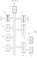
図1は、プログラムを実行することにより、本発明の決定装置の機能を果たす典型的な情報処理装置100の概要構成を示す模式図である。以下、本図を参照して説明する。
FIG. 1 is a schematic diagram showing a schematic configuration of a typical
情報処理装置100は、CPU(Central Processing Unit)101と、ROM(Read Only Memory)102と、RAM(Random Access Memory)103と、インターフェース104と、コントローラ105と、外部メモリ106と、DVD−ROM(Digital Versatile Disk - Read Only Memory)ドライブ107と、画像処理部108と、音声処理部109と、NIC(Network Interface Card)110と、を備える。
The
ゲーム用のプログラムおよびデータを記憶したDVD−ROMをDVD−ROMドライブ107に装着して、情報処理装置100の電源を投入することにより、当該プログラムが実行され、本実施形態の決定装置が実現される。
A DVD-ROM storing a game program and data is loaded into the DVD-
CPU 101は、情報処理装置100全体の動作を制御し、各構成要素と接続され制御信号やデータをやりとりする。また、CPU 101は、レジスタ(図示せず)という高速アクセスが可能な記憶域に対してALU(Arithmetic Logic Unit)(図示せず)を用いて加減乗除等の算術演算や、論理和、論理積、論理否定等の論理演算、ビット和、ビット積、ビット反転、ビットシフト、ビット回転等のビット演算などを行うことができる。さらに、マルチメディア処理対応のための加減乗除等の飽和演算や、三角関数等、ベクトル演算などを高速に行えるように、CPU 101自身が構成されているものや、コプロセッサを備えて実現するものがある。
The
ROM 102には、電源投入直後に実行されるIPL(Initial Program Loader)が記録され、これが実行されることにより、DVD−ROMに記録されたプログラムをRAM 103に読み出してCPU 101による実行が開始される。また、ROM 102には、情報処理装置100全体の動作制御に必要なオペレーティングシステムのプログラムや各種のデータが記録される。
The
RAM 103は、データやプログラムを一時的に記憶するためのもので、DVD−ROMから読み出したプログラムやデータ、その他ゲームの進行やチャット通信に必要なデータが保持される。また、CPU 101は、RAM 103に変数領域を設け、当該変数に格納された値に対して直接ALUを作用させて演算を行ったり、RAM 103に格納された値を一旦レジスタに格納してからレジスタに対して演算を行い、演算結果をメモリに書き戻す、などの処理を行う。
The
インターフェース104を介して接続されたコントローラ105は、プレイヤーがダンスゲームやサッカーゲームなどのゲームの実行の際に行う操作入力を受け付ける。インターフェース104には、複数のコントローラ105が接続されていてもよい。
The
インターフェース104を介して着脱自在に接続された外部メモリ106には、ゲームのプレイ状況(過去の成績等)を示すデータ、ゲームの進行状態を示すデータ、ネットワークを用いたゲームのチャット通信のログ(記録)のデータなどが書き換え可能に記憶される。プレイヤーは、コントローラ105を介して操作入力を行うことにより、これらのデータを適宜外部メモリ106に記録することができる。
The
DVD−ROMドライブ107に装着されるDVD−ROMには、ゲームを実現するためのプログラムとゲームに付随する画像データや音声データが記録される。CPU 101の制御によって、DVD−ROMドライブ107は、これに装着されたDVD−ROMに対する読み出し処理を行って、必要なプログラムやデータを読み出し、これらはRAM 103等に一時的に記憶される。
A DVD-ROM mounted on the DVD-
画像処理部108は、DVD−ROMから読み出されたデータをCPU 101や画像処理部108が備える画像演算プロセッサ(図示せず)によって加工処理した後、これを画像処理部108が備えるフレームメモリ(図示せず)に記録する。フレームメモリに記録された画像情報は、所定の同期タイミングでビデオ信号に変換され画像処理部108に接続されるモニター(図示せず)へ出力される。これにより、各種の画像表示が可能となる。
The image processing unit 108 processes the data read from the DVD-ROM by the
画像演算プロセッサは、2次元の画像の重ね合わせ演算やαブレンディング等の透過演算、各種の飽和演算を高速に実行できる。 The image calculation processor can execute a two-dimensional image overlay calculation, a transmission calculation such as α blending, and various saturation calculations at high speed.
また、仮想3次元空間に配置され、各種のテクスチャ情報が付加されたポリゴン情報を、Zバッファ法によりレンダリングして、所定の視点位置から仮想3次元空間に配置されたポリゴンを所定の視線の方向へ俯瞰したレンダリング画像を得る演算の高速実行も可能である。 Also, polygon information arranged in the virtual three-dimensional space and added with various texture information is rendered by the Z buffer method, and the polygon arranged in the virtual three-dimensional space from the predetermined viewpoint position is determined in the direction of the predetermined line of sight It is also possible to perform high-speed execution of operations for obtaining rendered images.
さらに、CPU 101と画像演算プロセッサが協調動作することにより、文字の形状を定義するフォント情報にしたがって、文字列を2次元画像としてフレームメモリへ描画したり、各ポリゴン表面へ描画することが可能である。
Further, the
また、ゲームの画像などの情報をDVD−ROMに用意しておき、これをフレームメモリに展開することによって、ゲームの様子などを画面に表示することができるようになる。 Further, by preparing information such as game images in a DVD-ROM and expanding the information in a frame memory, the state of the game can be displayed on the screen.
音声処理部109は、DVD−ROMから読み出した音声データをアナログ音声信号に変換し、これに接続されたスピーカー(図示せず)から出力させる。また、CPU 101の制御の下、ゲームの進行の中で発生させるべき効果音や楽曲データを生成し、これに対応した音声をスピーカーから出力させる。
The
音声処理部109では、DVD−ROMに記録された音声データがMIDIデータである場合には、これが有する音源データを参照して、MIDIデータをPCMデータに変換する。また、ADPCM(Adaptive Differential Pulse Code Modulation)形式やOgg Vorbis形式等の圧縮済音声データである場合には、これを展開してPCMデータに変換する。PCMデータは、そのサンプリング周波数に応じたタイミングでD/A(Digital/Analog)変換を行って、スピーカーに出力することにより、音声出力が可能となる。
When the audio data recorded on the DVD-ROM is MIDI data, the
NIC 110は、情報処理装置100をインターネット等のコンピュータ通信網(図示せず)に接続するためのものであり、LAN(Local Area Network)を構成する際に用いられる10BASE−T/100BASE−T規格にしたがうものや、電話回線を用いてインターネットに接続するためのアナログモデム、ISDN(Integrated Services Digital Network)モデム、ADSL(Asymmetric Digital Subscriber Line)モデム、ケーブルテレビジョン回線を用いてインターネットに接続するためのケーブルモデム等と、これらとCPU 101との仲立ちを行うインターフェース(図示せず)により構成される。
The
このほか、情報処理装置100は、ハードディスク等の大容量外部記憶装置を用いて、ROM 102、RAM 103、外部メモリ106、DVD−ROMドライブ107に装着されるDVD−ROM等と同じ機能を果たすように構成してもよい。
In addition, the
次に、上記構成を有する情報処理装置100により実現される、本実施形態の決定装置200の機能的な構成について説明する。
Next, a functional configuration of the
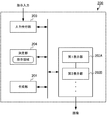
図2は、決定装置200の機能的な構成を説明するための図である。決定装置200は、生成部201、複数の表示部202(本実施形態では第1表示部202Aと第2表示部202Bの2つ)、入力受付部203、決定部204を備える。
FIG. 2 is a diagram for explaining a functional configuration of the
図3(a)〜(c)は、本実施形態の決定装置200が扱う仮想空間300を表す図である。
図4(a)〜(d)は、仮想空間300に設定される表示領域内に設定される周縁領域(詳細は後述する)を説明するための図である。
図5(a)と(b)は、決定装置200に接続されるモニターに表示される画面の構成を説明するための図である。
3A to 3C are diagrams illustrating the
4A to 4D are diagrams for explaining a peripheral area (details will be described later) set in a display area set in the
FIGS. 5A and 5B are diagrams for explaining a configuration of a screen displayed on a monitor connected to the
生成部201は、決定装置200のユーザに提示すべき画像を生成する。本実施形態において生成部201により生成される画像は、ユーザ(以下「プレイヤー」とも言う。)がコントローラ105を操作して行う仮想空間300内におけるゲームの画像である。ただし、生成部201によって生成される画像は、ゲームの画像に限られない。CPU 101と画像処理部108が協働して生成部201として機能する。
The
第1表示部202A,第2表示部202Bは、生成部201によって生成される画像のうち、後述のように設定される表示領域の中に含まれる画像をモニターに表示する。CPU 101は、仮想空間300内に複数の表示領域を設定する。
The
第1表示部202Aは第1表示領域310内を表す画像を表示し、第2表示部202Bは第2表示領域320内を表す画像を表示する。CPU 101と画像処理部108が協働して第1表示部202A,第2表示部202Bとして機能する。
The
本実施形態では、決定装置200は2つの表示部を備え、2つの表示領域を仮想空間300内に設定する。ただし、決定装置200が3つ以上の表示部を備え3つ以上の表示領域を仮想空間300内に設定する実施形態を採用することもできる。
In the present embodiment, the
ここで、表示領域について図3(a)〜(c)を用いて詳しく説明する。決定装置200によって実行されるゲームが扱う仮想空間300には、図3(a)に示すように、第1表示部202Aに対応付けられる第1表示領域310と、第2表示部202Bに対応付けられる第2表示領域320が設定される。また、仮想空間300を表す画像には、ポインタ画像330が含まれる。
Here, the display area will be described in detail with reference to FIGS. As shown in FIG. 3A, the
本実施形態で扱う仮想空間300は2次元空間であるが、3次元空間でもよい。3次元空間の場合、第1表示部202Aと第2表示部202Bによって表示される画像は、仮想空間300内に配置されるオブジェクトを、仮想空間300内に設定される視点の位置から視線の方向(仮想カメラの方向)へ所定の投影面に投影した画像である。
The
例えば、決定装置200は、1つのモニター(以下「ディスプレイ」とも言う。)に接続される。モニターに表示される画面には、隣り合う2つの画像エリア(いわゆる“ウインドウ”)が存在する。第1のウインドウ内には第1表示領域310内を表す画像が表示され、第2のウインドウ内には第2表示領域320内を表す画像が表示される。
For example, the
あるいは、決定装置200は、隣り合う2つのモニターに接続されていてもよい。例えば、一方のモニターには第1表示領域310内を表す画像が表示され、他方のモニターには第2表示領域320内を表す画像が表示されてもよい。
Alternatively, the
第1表示領域310の位置と第2表示領域320の位置は、仮想空間300内に予め定義されるグローバル座標系(図3(a)の場合、X−Y座標系である。)による位置座標値を用いて表される。第1表示領域310の位置と第2表示領域320の位置は、CPU 101の制御により移動可能である。
The position of the
例えば、CPU 101は、プレイヤーからの指示入力に基づいて、第1表示領域310の位置と第2表示領域320の仮想空間300内における位置を変える。第1表示領域310の位置及び/又は第2表示領域320の位置が移動すると、ウインドウあるいはモニターに表示される画像が変化する。この移動は、一般には“スクロール”と呼ばれる。
For example, the
第1表示領域310の形状は、図3(b)に示すように、4つの辺311〜314で囲まれる矩形である。同様に、第2表示領域320の形状は、図3(c)に示すように、4つの辺321〜324で囲まれる矩形である。
The shape of the
第1表示領域310と第2表示領域320は、仮想空間300内において互いに隣り合うように配置される。典型的には、第1表示領域310と第2表示領域320は、いずれか1つの辺どうしが重なるように、接している。図3(a)では、第1表示領域310の辺313と第2表示領域320の辺321とが重なっている。ただし、第1表示領域310と第2表示領域320は、必ずしも接していなくてもよく、所定の距離だけ離れていてもよいし、重なる部分があってもよい。
The
第1表示領域310と第2表示領域320は、次に示すいずれかの組み合わせの各辺が互いに隣り合うように、仮想空間300内に配置される。
The
(1)第1表示領域310の辺311と第2表示領域320の辺323の組み合わせ。
(2)第1表示領域310の辺312と第2表示領域320の辺324の組み合わせ。
(3)第1表示領域310の辺313と第2表示領域320の辺321の組み合わせ。
(4)第1表示領域310の辺314と第2表示領域320の辺322の組み合わせ。
(1) A combination of the
(2) A combination of the
(3) A combination of the
(4) A combination of the
本実施形態では、第1表示領域310と第2表示領域320は同一の形状且つ同一の大きさである。ただし、形状と大きさの両方あるいは一方が異なっていてもよい。
In the present embodiment, the
次に、入力受付部203は、仮想空間300を表す画像内における位置を指定する入力(指示入力)をユーザから受け付ける。CPU 101とコントローラ105が入力受付部203として機能する。
Next, the
例えば、ユーザ(プレイヤー)は、モニターに表示されるポインタ画像330の位置を、コントローラ105の上下左右ボタンを押圧することにより移動させる。ポインタ画像330は、第1表示領域310と第2表示領域320のどちらか一方に配置されるものとする。つまり、ユーザは、第1表示領域310内の任意の1箇所の位置、又は、第2表示領域320内の任意の1箇所の位置を指定することができる。
For example, the user (player) moves the position of the
ポインタ画像330の位置は、第1表示領域310と第2表示領域320に予め定義されるローカル座標系(図3(b),(c)の場合、x−y座標系である。)による位置座標値を用いて表される。CPU 101は、ローカル座標系からグローバル座標系に座標変換することにより、仮想空間300内におけるポインタ画像330の位置を求めることができる。ポインタ画像330の位置は、第1表示領域310内、又は、第2表示領域320内で移動可能である。
The position of the
ポインタ画像330が示す位置が、ユーザによって指定される位置である。図3(a)ではポインタ画像330の形状は十字形である。十字形の縦線と横線がクロスする点が、ユーザによって指定される位置である。
The position indicated by the
ただし、ポインタ画像330の形状や大きさを任意に変更してもよい。ポインタ画像330は、一般的には、マウスカーソル、マウスポインタなどと呼ばれることがある。
However, the shape and size of the
決定部204は、入力受付部203によって受け付けられた指示入力に指定される位置に対応付けられる指示領域を決定する。CPU 101と画像処理部108が協働して決定部204として機能する。
The
指示領域500は、図5(a)に示すように、ポインタ画像330の位置を含む所定の大きさ及び所定の形状を有する領域である。指示領域500は、ユーザが決定装置200に指示を与える際、指示対象を指定する領域である。
The
ユーザによって指定される位置を上述のように十字形の縦線と横線がクロスする点のみとすると、ユーザは、1ドット〜数ドット程度の正確さで位置を指定しなければならない。しかし、指示領域500を設けることにより、ユーザによって指定される位置の誤差が指示領域500の広さの分だけ許容される。
If the position specified by the user is only the point where the cross-shaped vertical and horizontal lines cross as described above, the user must specify the position with an accuracy of about one dot to several dots. However, by providing the
例えば、第1表示領域310及び/又は第2表示領域320にはキャラクタオブジェクト550(以下「オブジェクト」と呼ぶ。図5(a),(b)では550A,550B,550Cの3つ。)の画像が配置される。指示領域500内にオブジェクト550が存在すると、CPU 101は、指示領域500内に存在するオブジェクト550がユーザによって選択されたと判別する。指示領域500は、決定装置200がユーザによって選択されるオブジェクト550を判別するために用いられる。
For example, in the
あるいは、指示領域500内にオブジェクト550が存在し、且つ、ユーザによる所定の指示操作(例えばマウスのクリック操作など)があると、CPU 101は、指示領域500内に存在するオブジェクト550がユーザによって選択されたと判別してもよい。
Alternatively, when the object 550 exists in the
仮想空間300内におけるオブジェクト550と第1表示領域310と第2表示領域320との位置関係によっては、例えば図5(a),(b)に示すオブジェクト550Bのように、仮想空間300内に存在する1つのオブジェクト550が、第1表示領域310内と第2表示領域320内の両方に同時に存在する場合もある。
Depending on the positional relationship among the object 550, the
指示領域500の形状は、例えば、ポインタ画像330が示す位置を取り囲む多角形である。典型的には、ポインタ画像330が示す位置が、指示領域500を表す図形の中心点や重心点になる。指示領域500の形状は本発明によって限定されない。指示領域500は、ポインタ画像330が示す位置を中心(あるいは重心)とする円、楕円、あるいは、任意の形状の図形で表される領域でもよい。
The shape of the
指示領域500の位置は、仮想空間300内に定義されるグローバル座標系を用いる座標値、又は、第1表示領域310内に定義されるローカル座標系を用いる座標値、又は、第2表示領域320内に定義されるローカル座標系を用いる座標値で表される。
The position of the
CPU 101は、指示領域500の大きさと形状を、ポインタ画像330の位置に応じて変化させることができる。
The
すなわち、ポインタ画像330の位置がそれぞれの表示領域について定義される周縁領域に含まれない場合、CPU 101は、指示領域500を第1の大きさに設定する。一方、ポインタ画像330の位置が周縁領域に含まれる場合、CPU 101は、指示領域500を第1の大きさよりも面積が広い第2の大きさに設定する。
That is, when the position of the
例えば図4(a)に示すように、第1表示領域310を構成する4辺の近くに4つの領域411〜414が定義される。領域411〜414のそれぞれが、第1表示領域310の周縁領域である。あるいは、4つの領域411〜414をまとめて1つの周縁領域として定義してもよい。
For example, as shown in FIG. 4A, four
同様に、第2表示領域320を構成する4辺の近くに4つの領域421〜424が定義される。領域421〜424のそれぞれが、第2表示領域320の周縁領域である。あるいは、4つの領域421〜424をまとめて1つの周縁領域として定義してもよい。
Similarly, four
例えば図4(b)に示すように、領域411〜414及び領域421〜424のうち、隣り合う領域413と領域421のみを周縁領域として定義してもよい。
For example, as shown in FIG. 4B, out of the
例えば図4(c)に示すように、第1表示領域310のうち第2表示領域320側の幅C1の領域415と、第2表示領域320のうち第1表示領域310側の幅C2の領域425とを、それぞれ周縁領域として定義してもよい。C1とC2は、ゼロ以上の任意の値である。
For example, as shown in FIG. 4C, a
第1表示領域310と第2表示領域320は、図4(a)〜(c)に示すようにY軸方向に隣り合ってもよいし、図4(d)に示すようにX軸方向に隣り合っていてもよい。そして、第1表示領域310のうち第2表示領域320側の幅C3の領域416と、第2表示領域320のうち第1表示領域310側の幅C4の領域426とを、それぞれ周縁領域として定義してもよい。C3とC4は、ゼロ以上の任意の値である。
The
本実施形態では、図5(a)に示すように、ポインタ画像330が頂点P5,P6,P7,P8で囲まれる範囲(周縁領域ではない範囲)内にある場合、CPU 101は、指示領域500の大きさを所定の第1の大きさに設定する。図5(a)では、指示領域500は、一辺の長さがL1の正方形に設定されている。
In the present embodiment, as illustrated in FIG. 5A, when the
一方、図6(a)に示すように、ポインタ画像330が第1表示領域310内に設定される周縁領域の中にある場合、CPU 101は、指示領域500の大きさを所定の第2の大きさに設定する。図6(a)では、指示領域500は、一辺の長さがL2(L1<L2)の正方形に設定されている。
On the other hand, as shown in FIG. 6A, when the
第1表示領域310には、4つの周縁領域511〜514が設定される。周縁領域511〜514のそれぞれは、第1表示領域310の周縁領域を構成する単位領域とも呼ばれる。
In the
周縁領域511は、頂点P1,P2,P6,P5を結ぶ線で囲まれる領域である。周縁領域511は、第1表示領域310の辺311に対応付けられる。
周縁領域512は、頂点P2,P3,P7,P6を結ぶ線で囲まれる領域である。周縁領域512は、第1表示領域310の辺312に対応付けられる。
周縁領域513は、頂点P3,P4,P8,P7を結ぶ線で囲まれる領域である。周縁領域513は、第1表示領域310の辺313に対応付けられる。
周縁領域514は、頂点P4,P1,P5,P8を結ぶ線で囲まれる領域である。周縁領域514は、第1表示領域310の辺314に対応付けられる。
The
The
The
The
同様に、図6(b)に示すように、ポインタ画像330の位置が第2表示領域320の周縁領域521,522,523,524のいずれかの中にある場合、CPU 101は、指示領域500を所定の第3の大きさに設定する。図6(b)では、指示領域500は、一辺の長さがL3(L1<L3)の正方形に設定されている。なお、第2の大きさと第3の大きさは同じでも良い。
Similarly, as illustrated in FIG. 6B, when the position of the
第2表示領域320には、4つの周縁領域521〜524が設定される。周縁領域521〜524のそれぞれは、第2表示領域320の周縁領域を構成する単位領域とも呼ばれる。
In the
周縁領域521は、頂点P9,P10,P14,P13を結ぶ線で囲まれる領域である。周縁領域521は、第2表示領域320の辺321に対応付けられる。
周縁領域522は、頂点P10,P11,P15,P14を結ぶ線で囲まれる領域である。周縁領域522は、第2表示領域320の辺322に対応付けられる。
周縁領域523は、頂点P11,P12,P16,P15を結ぶ線で囲まれる領域である。周縁領域523は、第2表示領域320の辺323に対応付けられる。
周縁領域524は、頂点P12,P9,P13,P16を結ぶ線で囲まれる領域である。周縁領域524は、第2表示領域320の辺324に対応付けられる。
The
The
The
The
図5(a),図5(b),図6(a),図6(b)に示す周縁領域511〜514、521〜524は例示に過ぎない。周縁領域511〜514、521〜524の形状と大きさは本発明によって限定されず、任意に設定した実施形態を採用することができる。
The
また、辺の長さL1,L2,L3は自由に変更できる。ただし、L1<L2、且つ、L1<L3とする。 Further, the side lengths L1, L2, and L3 can be freely changed. However, L1 <L2 and L1 <L3.
なお、本実施形態では、指示領域500は後述する決定処理を行うために内部的に設定され、CPU 101はモニターに指示領域500を明示的に表示させることはないものとする。ただし、CPU 101は、仮想空間300のうち指示領域500が占める領域の明度・彩度・色相(これら3つをまとめて「色調」ともいう。)のうちいずれか1つ以上を変更して表示してもよい。
In this embodiment, it is assumed that the
次に、上記構成を備える本実施形態の決定装置200の各部が実行する決定処理について、図7のフローチャート等を用いて説明する。
Next, determination processing executed by each unit of the
まず、CPU 101は、仮想空間300内における第1表示領域310の位置と第2表示領域320の位置とを決定する(ステップS701)。例えばCPU 101は、第1表示領域310及び/又は第2表示領域320の位置を移動させる旨の操作入力をユーザから受け付け、第1表示領域310及び/又は第2表示領域320の仮想空間300における位置を移動する。
First, the
第1表示領域310の位置が決まると、CPU 101は、仮想空間300全体を表す画像のうち第1表示領域310内を表す画像を第1のウインドウ(もしくは第1のモニター)に表示させる。同様に、第2表示領域320の位置が決まると、CPU 101は、仮想空間300全体を表す画像のうち第2表示領域320内を表す画像を第2のウインドウ(もしくは第2のモニター)に表示させる(ステップS702)。
When the position of the
CPU 101は、第1表示領域310内の位置を指定する指示入力、又は、第2表示領域320内の位置を指定する指示入力をユーザから受け付ける(ステップS703)。
The
例えばユーザは、コントローラ105を操作して、第1表示領域310内もしくは第2表示領域320内に表示されるポインタ画像330の位置を移動させる。ポインタ画像330によって示される位置が、指示入力により指定される位置である。
For example, the user operates the
CPU 101は、ステップS703で受け付けられた指示入力が示す位置が、第1表示領域310の周縁領域511〜514と第2表示領域320の周縁領域521〜524のいずれかに含まれるか否かを判別する(ステップS704)。
The
周縁領域511〜514と周縁領域521〜524のいずれにも含まれないと判別された場合(ステップS704;NO)、CPU 101は、ステップS703で受け付けられた指示入力が示す位置を含み、且つ、第1の大きさをもつ指示領域500を決定する(ステップS705)。
When it is determined that none of the
例えば図5(a)に示すように、ポインタ画像330の位置が周縁領域511〜514のいずれにも含まれない場合、CPU 101は、ポインタ画像330の位置を重心とし1辺の長さがL1の正方形で囲まれる領域を指示領域500に設定する。
For example, as illustrated in FIG. 5A, when the position of the
一方、周縁領域511〜514と周縁領域521〜524のうちいずれか1つの周縁領域に含まれると判断された場合(ステップS704;YES)、CPU 101は、ステップS703で受け付けられた指示入力が示す位置を含み、且つ、第1の大きさよりも大きい第2の大きさをもつ指示領域500を決定する(ステップS706)。
On the other hand, when it is determined that any one of the
例えば図6(a)に示すように、ポインタ画像330の位置が周縁領域513に含まれる場合、CPU 101は、ポインタ画像330の位置を重心とし1辺の長さがL2(L1<L2)の正方形で囲まれる領域を指示領域500に設定する。
For example, as shown in FIG. 6A, when the position of the
すなわち、ポインタ画像330が示す位置がいずれかの周縁領域の中であれば、指示領域500が大きくなる。
That is, if the position indicated by the
更に、CPU 101は、ステップS706で決定された指示領域500にオブジェクト550の位置が含まれるか否かを判別する(ステップS707)。
Further, the
指示領域500にオブジェクト550の位置が含まれないと判別された場合(ステップS707;NO)、CPU 101は決定処理を終了する。
When it is determined that the position of the object 550 is not included in the instruction area 500 (step S707; NO), the
指示領域500にオブジェクト550の位置が含まれると判別された場合(ステップS707;YES)、CPU 101は、そのオブジェクト550がユーザによって選択されたと判別する(ステップS708)。
When it is determined that the position of the object 550 is included in the instruction area 500 (step S707; YES), the
例えば、CPU 101は、仮想空間300内をランダムに移動するオブジェクト550の位置にプレイヤーがポインタ画像330を合わせることによりプレイヤーがオブジェクト550を“捕獲”するゲームを実行する。CPU 101は、ユーザからの入力に応じてゲームを進行させる。CPU 101は、指示領域500にオブジェクト550の位置が含まれると判別された場合、そのオブジェクト550がプレイヤーによって“捕獲”されたと判別する。そして、CPU 101は、プレイヤーのスコアに所定ポイントを加算する。
For example, the
本実施形態では、ポインタ画像330の位置がいずれかの周縁領域に含まれるときには、指示領域500が広く設定されるので、オブジェクト550の位置が指示領域500の中に入りやすくなる。ユーザは、第1表示領域310又は第2表示領域320の境界に近い部分の位置を指定しやすくなる。
In the present embodiment, when the position of the
例えば図6(a)に示されるオブジェクト550Bは、第1表示領域310の隅に配置されている。第1表示領域310内にはオブジェクト550Bの一部分しか表示されず、ユーザがピンポイントでオブジェクト550Bを指し示すことは比較的難しくなる。
また例えば、オブジェクト550Bが第1表示領域310と第2表示領域320とを行き来するように移動する。ユーザは2つの表示領域を瞬時に見比べながらどちらの表示領域内を指せばよいのか判断する必要があり、ユーザがピンポイントで550Bを指し示すことは難しくなる。このため、表示領域の周縁領域付近、言い換えれば、画面の隅において、ゲームが極端に難しくなってしまう恐れがある。
For example, an
Further, for example, the
しかし、本実施形態によれば、周縁領域付近では指示領域500が広がるので、実質的にオブジェクト550とポインタ画像330の当たり判定が緩くなる。周縁領域付近においてユーザが位置を指定しづらくなる可能性があるものの、決定装置200は当たり判定を緩くすることができるので、ゲームの難易度のバランスを調節できるようになる。決定装置200は、表示される画面の隅の位置をユーザが指定しやすくすることができる。
However, according to the present embodiment, since the
CPU 101は、例えば、初心者がゲームをプレイしていると判断あるいは推定されるときには、ポインタ画像330の位置が周縁領域の中に入ると、指示領域500を広く設定する。一方、上級者がゲームをプレイしていると判断あるいは推定されるときには、CPU 101は、ポインタ画像330の位置が周縁領域の中に入っても指示領域500を広く設定せず既定値のままにする。このようにすれば、まだゲーム慣れしていない初心者をアシストできる機能をゲームに搭載することができる。
For example, when it is determined or estimated that a beginner is playing a game, the
CPU 101は、プレイヤーによる選択入力に従って、プレイヤーが初心者か否かを判断してもよい。
The
CPU 101は、ゲームをプレイした回数、ゲームをプレイした(ゲームをプレイしている)時間、ゲームをプレイする(ゲームをプレイしている)時間帯、ゲームをプレイする頻度、その他ゲームについての履歴を表す情報を外部メモリ106等に格納させ、適宜更新し、格納されるこれらの情報に基づいて、ユーザの上達度が所定レベル以上か否かを推定してもよい。CPU 101は、ユーザの上達度が所定レベル以上であれば上級者であると推定し、所定レベル未満であれば初心者であると推定してもよい。
また、例えば、プレイヤーがゲームをしている日時(つまり現在時刻や現在日時)が所定の時間帯(夜間帯など)の場合であって、ポインタ画像330の位置が周縁領域の中に入った場合、CPU 101は、指示領域500を広く設定してもよい。このようにすれば、暗くて画面が見えづらいと推測されるケースでも、プレイヤーが画面の隅を指しやすくなり、プレイヤーがゲームを進めやすくすることができる。
In addition, for example, when the date and time when the player is playing the game (that is, the current time and current date and time) is in a predetermined time zone (such as the night time zone), and the position of the
(実施形態2)
次に、本発明のその他の実施形態について説明する。本実施形態では、ポインタ画像330が複数の周縁領域のうちどの周縁領域の中にあるかによって指示領域500の大きさや形状が変わる。
(Embodiment 2)
Next, other embodiments of the present invention will be described. In the present embodiment, the size and shape of the
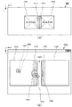
図8(a)は、画面800の構成例を示す図である。
図8(b)は、画面800が表示されるディスプレイ830,840の配置例を示す図である。
FIG. 8A is a diagram illustrating a configuration example of the
FIG. 8B is a diagram illustrating an arrangement example of the
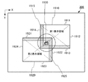
図8(c)は、仮想空間300内に設定される第1表示領域310と第2表示領域320を示す図である。本実施形態では、第1表示領域310と第2表示領域320は、図8(c)に示すように、第1表示領域310の所定の一辺と第2表示領域320の所定の一辺とが重なるように、隣り合わせに配置される。
FIG. 8C is a diagram illustrating the
図8(a)に示すように、モニターに映し出される画面800には、第1表示領域310を表す画像が出力される第1のウインドウ810と、第2表示領域320を表す画像が出力される第2のウインドウ820が、仮想空間300内の第1表示領域310と第2表示領域320との位置関係が保たれるように、隣り合わせに配置される。
As shown in FIG. 8A, on the
あるいは、図8(b)に示すように、第1表示領域310を表す画像が出力される第1のディスプレイ830と、第2表示領域320を表す画像が出力される第2のディスプレイ840は、仮想空間300内の第1表示領域310と第2表示領域320との位置関係が保たれるように、隣り合わせに配置される。
Alternatively, as shown in FIG. 8B, a
第1のウインドウ810(もしくは第1のディスプレイ830)と第2のウインドウ820(もしくは第2のディスプレイ840)は、互いに接していてもよいし、離れていてもよい。 The first window 810 (or the first display 830) and the second window 820 (or the second display 840) may be in contact with each other or may be separated from each other.
例えば図8(c)に示すように、仮想空間300には、第1表示領域310が第2表示領域320の上側(Y座標が小さい側)に配置される。
For example, as shown in FIG. 8C, in the
また、図8(a)に示すように、第1のウインドウ810と第2のウインドウ820は、プレイヤーから見て第1表示領域310を表す画像が上に、第2表示領域320を表す画像が下になるように、それぞれ配置される。
Further, as shown in FIG. 8A, in the
例えば、画面800の左上の隅を原点とするローカル座標系(図8(a)の場合、p−q座標系である。)が画面800内に定義される。図8(c)に示すように、第1表示領域310と第2表示領域320は、仮想空間300に定義されるグローバル座標系(X−Y座標系)において、第1表示領域310内の任意の点のY座標値が、第2表示領域320内の任意の点のY座標値よりも小さくなるように、配置される。
For example, a local coordinate system having the origin at the upper left corner of the screen 800 (in the case of FIG. 8A, a pq coordinate system) is defined in the
第1表示領域310と第2表示領域320は、画面800に定義されるローカル座標系(p−q座標系)において、第1表示領域310内の任意の点のq座標値が、第2表示領域320内の任意の点のq座標値よりも小さくなるように、配置される。
In the
第1表示領域310の周縁領域513と第2表示領域320の周縁領域521は、隣り合って表示される。
The
次に、本実施形態の決定処理について、図9のフローチャートを用いて説明する。 Next, the determination process of this embodiment will be described with reference to the flowchart of FIG.
まず、CPU 101は、仮想空間300内における第1表示領域310の位置と第2表示領域320の位置とを決定する(ステップS901)。
First, the
第1表示領域310の位置が決まると、CPU 101は、仮想空間300全体を表す画像のうち第1表示領域310内を表す画像を第1のウインドウ810に表示させる。同様に、第2表示領域320の位置が決まると、CPU 101は、仮想空間300全体を表す画像のうち第2表示領域320内を表す画像を第2のウインドウ820に表示させる(ステップS902)。
When the position of the
CPU 101は、第1表示領域310内の任意の位置を指定する指示入力、又は、第2表示領域320内の任意の位置を指定する指示入力をユーザから受け付ける(ステップS903)。
The
CPU 101は、ステップS903で受け付けられた指示入力が示す位置が、すべての周縁領域のうち隣り合う周縁領域のいずれかに含まれるか否かを判別する。すなわち、CPU 101は、ステップS903で受け付けられた指示入力が示す位置が、第1表示領域310の周縁領域513又は第2表示領域320の周縁領域521に含まれるか否かを判別する(ステップS904)。
The
指示入力が示す位置が隣り合う周縁領域のいずれにも含まれないと判別された場合(ステップS904;NO)、CPU 101は、指示領域500の大きさを、所定の第1の大きさに決定する(ステップS905)。
When it is determined that the position indicated by the instruction input is not included in any of the adjacent peripheral areas (step S904; NO), the
そして、CPU 101は、第1表示領域310と第2表示領域320のうちポインタ画像330の位置が含まれるほうに、第1の大きさの指示領域500を設定する(ステップS906)。
Then, the
つまり、CPU 101は、ポインタ画像330の位置が第1表示領域310内にある場合には、第1表示領域310内に指示領域500を設定し、ポインタ画像330の位置が第2表示領域320内にある場合には、第2表示領域320内に指示領域500を設定する。
That is, when the position of the
一方、ポインタ画像330の位置が隣り合う周縁領域のいずれかに含まれると判断された場合(ステップS904;YES)、CPU 101は、指示領域500の大きさを、所定の第2の大きさに決定する(ステップS907)。第2の大きさは、第1の大きさよりも大きい。
On the other hand, when it is determined that the position of the
そして、CPU 101は、第1表示領域310及び/又は第2表示領域320に、第2の大きさの指示領域500を設定する(ステップS908)。
Then, the
ここで、「第1表示領域310“又は”第2表示領域320」に指示領域500を設定する場合とは、図10(a)に示すように指示領域500全体が第1表示領域310の中に収まる場合、もしくは、指示領域500全体が第2表示領域320の中に収まる場合のことである。
Here, when the
例えば、指示領域500を、一辺の長さがL2であってポインタ画像330の位置を重心位置とする正方形に設定するとき、第1表示領域310の辺313とポインタ画像330との距離がL2/2(長さL2の半分)以上であれば、指示領域500全体が第1表示領域310の中に収まる。指示領域500全体が第2表示領域320の中に収まる場合も同様である。
For example, when the
また、「第1表示領域310“及び”第2表示領域320」に指示領域500を設定する場合とは、図10(b)に示すように指示領域500全体が第1表示領域310の中に収まりきらずに第2表示領域320にも含まれる場合、もしくは、指示領域500全体が第2表示領域320の中に収まりきらずに第1表示領域310にも含まれる場合のことである。
Further, when the
例えば、指示領域500を、一辺の長さがL2であってポインタ画像330の位置を重心位置とする正方形に設定するとき、第1表示領域310の辺313とポインタ画像330との距離がL2/2(長さL2の半分)未満であれば、指示領域500全体が第1表示領域310の中に収まらない。このとき、第1表示領域310には、指示領域500全体のうち上から長さL2Aの部分だけが含まれる。
For example, when the
第1表示領域310内に指示領域500全体が収まらない場合、CPU 101は、収まらない部分、つまり指示領域500全体のうち下から長さL2Bの部分(ただしL2A+L2B=L2とする)を、第2表示領域320に配置する。
If the
なお、CPU 101は、L2A+L2B>L2となるように、すなわち、画面800を見るユーザにとって、隣り合う周縁領域の向きに“間延び”するように、指示領域500を拡張してもよい。
Note that the
次に、CPU 101は、ステップS906又はS908で設定した指示領域500に、オブジェクト550の位置が含まれるか否かを判別する(ステップS909)。
Next, the
指示領域500にオブジェクト550の位置が含まれないと判別された場合(ステップS909;NO)、CPU 101は決定処理を終了する。
When it is determined that the position of the object 550 is not included in the instruction area 500 (step S909; NO), the
指示領域500にオブジェクト550の位置が含まれると判別された場合(ステップS909;YES)、CPU 101は、そのオブジェクト550がユーザによって選択されたと判別する(ステップS910)。
When it is determined that the position of the object 550 is included in the instruction area 500 (step S909; YES), the
本実施形態では、ポインタ画像330の位置が隣り合う周縁領域の中のいずれかに含まれるときには、指示領域500が広く設定されるので、オブジェクト550の位置が指示領域500に入りやすくなる。ユーザは、第1表示領域310のうち第2表示領域320に近い部分の位置や、第2表示領域320のうち第1表示領域310に近い部分の位置を指定しやすくなる。
In the present embodiment, when the position of the
例えば、図8(a)に示されるオブジェクト550Bは、第1表示領域310の隅に配置されている。第1表示領域310内にはオブジェクト550Bの一部分しか表示されないため、ユーザがピンポイントでオブジェクト550Bを指し示すことが難しくなる。
また例えば、第1のウインドウ810と第2のウインドウ820との“隙間”があると、この隙間をユーザが誤って指してしまう可能性があり、ユーザがピンポイントでオブジェクト550Bを指し示すことが難しくなる。つまり、周縁領域付近(画面の隅)において、ゲーム制作者の意図に反して、ゲームが極端に難しくなってしまう恐れがある。
For example, the
Further, for example, if there is a “gap” between the
しかし、本実施形態によれば、他の表示領域と隣り合う周縁領域付近では指示領域500が広がるので、実質的にオブジェクト550とポインタ画像330の当たり判定が緩くなる。他の表示領域と隣り合う周縁領域付近においてユーザが位置を指定しづらくなる可能性があるものの、決定装置200は当たり判定を緩くすることができるので、ゲームの難易度のバランスを調節できるようになる。ユーザは、表示される画面の隅の位置を指定しやすくなる。
However, according to the present embodiment, the
(実施形態3)
次に、本発明のその他の実施形態について説明する。
図11は、本実施形態の決定装置200の機能的な構成を示す図である。決定装置200は、出力部1101を更に備える。
(Embodiment 3)
Next, other embodiments of the present invention will be described.
FIG. 11 is a diagram illustrating a functional configuration of the
出力部1101は、オブジェクト550と指示領域500が重なる場合、言い換えればオブジェクト550の位置が指示領域500に含まれる場合、オブジェクト550を示す情報を選択結果として出力する。CPU 101と画像処理部108が協働して出力部1101として機能する。
When the object 550 and the
オブジェクト550を示す情報とは、例えば図12に示すように、オブジェクト550がユーザによって選択された旨を示すメッセージ1200である。あるいは、オブジェクト550がユーザによって選択された旨を示す画像データでもよい。
The information indicating the object 550 is a
また、CPU 101は、オブジェクト550と指示領域500が重なる場合、画像処理部108を制御してメッセージ1200を表示するのに加えて、あるいはメッセージ1200を表示する代わりに、音声処理部109を制御して所定の音声データを再生することにより、オブジェクト550を示す情報を選択結果として出力してもよい。
When the object 550 and the
例えば、CPU 101は、上記ステップS708もしくはステップS910でオブジェクト550がユーザによって選択されたと判別した後、オブジェクト550を示す情報を出力する。
For example, after determining that the object 550 has been selected by the user in step S708 or step S910, the
なお、CPU 101は、オブジェクト550の位置が指示領域500に含まれ、且つ、所定の入力操作がなされた場合に、オブジェクト550を示す情報を選択結果として出力してもよい。所定の入力操作とは、例えば、マウスのクリック操作、ダブルクリック操作、所定ボタンの押圧操作などである。
Note that the
本実施形態によれば、ユーザは、指示領域500の中にオブジェクト550の位置を合わせることができたか否かを明確に把握できる。ユーザは、現在指示領域500がどこに設定されているのかを容易に把握できる。
According to the present embodiment, the user can clearly grasp whether or not the position of the object 550 can be aligned in the
(実施形態4)
次に、本発明のその他の実施形態について説明する。本実施形態では、ポインタ画像330の位置が周縁領域の中にあるか否かによって、ポインタ画像330の表示形式が変化する。
(Embodiment 4)
Next, other embodiments of the present invention will be described. In the present embodiment, the display format of the
図13は、第1表示領域310を表す画像の例を示す図である。
FIG. 13 is a diagram illustrating an example of an image representing the
CPU 101は、ユーザにより指定される位置が第1表示領域310の周縁領域のいずれにも含まれない場合には、既定値の大きさのポインタ画像1310を表示する。一方、CPU 101は、ユーザにより指定される位置が第1表示領域310の周縁領域のいずれかに含まれる場合には、既定値よりサイズが拡大されたポインタ画像1330を表示する。
When the position designated by the user is not included in any of the peripheral areas of the
また、CPU 101は、ユーザにより指定される位置が第1表示領域310の周縁領域のいずれにも含まれない場合には、第1の大きさの指示領域1320を設定する。一方、CPU 101は、ユーザにより指定される位置が第1表示領域310の周縁領域のいずれかに含まれる場合には、第2の大きさの指示領域1340を設定する。上述のように、第2の大きさは第1の大きさよりも大きい。
When the position designated by the user is not included in any of the peripheral areas of the
図13には2つのポインタ画像1310,1330が図示されているが、これは大きさを比較し易いように便宜的に記載したものであり、モニターにはどちらか1つのポインタ画像が表示される。同様に、図13には2つの指示領域1320,1340が図示されているが、仮想空間300にはどちらか1つの指示領域が設定される。また、指示領域1320,1340の位置や形状を示す情報は、モニターに表示されなくてもよい。
Although two
CPU 101は、ユーザにより指定される位置が第1表示領域310の周縁領域のいずれかに含まれる場合、その周縁領域に対応する辺とユーザにより指定される位置(ポインタ画像1330の位置)との距離Dが短いほど大きくなるように、ポインタ画像1330を拡大して表示してもよい。
When the position specified by the user is included in any of the peripheral areas of the
例えば図13に示すように周縁領域513の幅がD1であるとき、CPU 101は、図14(a)に示すように、0≦D≦D1において、ポインタ画像1330の表示サイズの拡大率Zを距離Dに対して単調減少させる。拡大率は1≦Z≦ZMAXの範囲で変化する。一方、D>D1では、CPU 101は、既定値の大きさ(つまり拡大率Z=1)のポインタ画像1310を表示させる。このようにすれば、ユーザが指定する位置が第1表示領域310の“際”に近いところであればあるほどポインタ画像1330が大きくなるので、ユーザは現在どの位置を指定しているのかが分かりやすくなる。
For example, when the width of the
あるいは図14(b)に示すように、CPU 101は、周縁領域513の幅の大きさに関係なく、ポインタ画像1330の表示サイズの拡大率Zを距離Dに対して単調減少させてもよい。拡大率はZMIN≦Z≦ZMAXの範囲で変化する。CPU 101はD≧D2(D2は所定値)では拡大率を一定にすることが望ましい。D2の値は、典型的には、0(ゼロ)以上、周縁領域513に対応する辺313と第1表示領域310の中心点との距離以下、である。
Alternatively, as illustrated in FIG. 14B, the
ここでは第1表示領域310の周縁領域513を例にとって説明した。しかし、CPU 101は、第1表示領域310の他の周縁領域511,512,514あるいは第2表示領域320の周縁領域521〜524においても同様にポインタ画像1310,1330の大きさを変化させることができる。
Here, the
また、CPU 101は、ポインタ画像1310,1330の大きさを変化させるだけでなく、ポインタ画像1310,1330の色調や点滅の速度などを変化させることができる。
In addition, the
例えば、CPU 101は、距離Dが減少するほど明度を大きくして、ポインタ画像1310,1330を表示してもよい。つまり、ユーザが指定した位置が表示領域の“際”に近いほど、ポインタ画像1310,1330が明るく表示される。従って、周縁領域に近いとポインタ画像1310,1330が強調表示されるので、ユーザはポインタ画像1310,1330が指し示す位置を把握しやすくなり、周縁領域付近(画面の隅)を指定しやすくなる。CPU 101は、ポインタ画像1310,1330の明度、彩度、色相の少なくとも1つ以上を任意に変化させることができる。
For example, the
なお、CPU 101は、ユーザにより指定される位置が、第1表示領域310の周縁領域のうち第2表示領域320と隣り合う周縁領域のいずれかに含まれる場合に、ポインタ画像330の表示形式を変化させるようにしてもよい。
The
本実施形態によれば、ユーザは、指定する位置が周縁領域に含まれるのか否か、あるいは、指定する位置が表示領域の境界にどの程度近いのかといった情報を簡単かつ明瞭に把握できるようになる。そして、ユーザは、表示領域の境界近くを指定し易くなる。 According to the present embodiment, the user can easily and clearly grasp information such as whether or not the designated position is included in the peripheral area, or how close the designated position is to the boundary of the display area. . The user can easily specify the vicinity of the boundary of the display area.
(実施形態5)
次に、本発明のその他の実施形態について説明する。
(Embodiment 5)
Next, other embodiments of the present invention will be described.
図15(a)は、本実施形態の第1表示領域1510と第2表示領域1520を表す図である。上記実施形態では、第1表示領域310と第2表示領域320がY方向に隣り合って配置されているが、本実施形態では、第1表示領域1510と第2表示領域1520がX方向に隣り合うように配置される。
FIG. 15A is a diagram showing the
図15(b)は、モニターに表示される画面1500の構成例を示す図である。画面1500には、第1表示領域1510内の画像を表示する第1のウインドウ1530と、第2表示領域内1520内の画像を表示する第2のウインドウ1540とが含まれる。
FIG. 15B is a diagram illustrating a configuration example of a
第1表示領域1510内には1つの周縁領域1515が定義される。第2表示領域1520内には1つの周縁領域1525が定義される。周縁領域1515と周縁領域1525は、画面1500内で隣り合うように配置される。図15(b)に示すように、1つの表示領域につき、1つの周縁領域のみが対応付けられてもよい。
One
第1のウインドウ1530と第2のウインドウ1540の間には所定幅の隙間1590が設けられている。所定幅の大きさは任意である。例えば所定幅の大きさをゼロにすれば、第1のウインドウ1530と第2のウインドウ1540は隣接することになる。
A
上記実施形態では、CPU 101は仮想空間300内にポインタ画像330を配置しているが、本実施形態では、CPU 101は画面1500内にポインタ画像1550,1570を配置する。つまり、図15(b)に示すように、ポインタ画像1550,1570が第1のウインドウ1530又は第2のウインドウ1540からはみ出して表示されることがある。
In the above embodiment, the
図15(b)には2つのポインタ画像1550,1570が記載されているが、これはポインタ画像1550,1570のサイズの違いを分かりやすくするために記載しただけである。画面1500内には、ポインタ画像1550,1570のどちらか一方が表示されるものとする。
In FIG. 15B, two
ユーザによって指示された位置が周縁領域1515,1525に含まれない場合、CPU 101は、ユーザによって指示された位置に既定値のサイズのポインタ画像1550を配置する。そして、CPU 101は、ユーザによって指示された位置を含む指示領域1560を仮想空間300内に設定する。
When the position designated by the user is not included in the
また、ユーザによって指示された位置が周縁領域1515,1525のどちらかに含まれる場合、CPU 101は、ユーザによって指示された位置に既定値より大きいサイズのポインタ画像1570を配置する。典型的には、CPU 101は、ポインタ画像1550を任意の拡大率で拡大した画像を、ポインタ画像1570とする。
When the position designated by the user is included in one of the
そして、CPU 101は、ユーザによって指示された位置を含む指示領域1580を仮想空間300内に設定する。指示領域1580の面積は、指示領域1560の面積よりも広い。
Then, the
なお、CPU 101は、ポインタ画像1550に任意の画像変換処理を施して生成した画像を、ポインタ画像1570としてもよい。例えば、CPU 101は、ポインタ画像1550に、所定方向への拡大又は縮小、所定角度の回転、色調(明度・彩度・色相)の変更、等の処理を施して生成した画像を、ポインタ画像1570とすることができる。
Note that the
(実施形態6)
次に、本発明のその他の実施形態について説明する。上記実施形態では、ユーザによって指示される位置に応じて指示領域500の大きさが変化するが、本実施形態では、大きさの代わりに、もしくは大きさに加えて、形状を変化させている。ここでは、上記実施形態5の変形例として、特徴を説明する。
(Embodiment 6)
Next, other embodiments of the present invention will be described. In the above embodiment, the size of the
図16(a)は、本実施形態の第1表示領域1610と第2表示領域1620を表す図である。本実施形態では、第1表示領域1610と第2表示領域1620がX方向に隣り合うように配置される。
FIG. 16A is a diagram showing the
図16(b)は、モニターに表示される画面1600の構成例を示す図である。画面1600には、第1表示領域1610内の画像を表示する第1のウインドウ1630と、第2表示領域内1620内の画像を表示する第2のウインドウ1640とが含まれる。
FIG. 16B is a diagram illustrating a configuration example of a
ユーザによって指示された位置が周縁領域1615,1625に含まれない場合、CPU 101は、ユーザによって指示された位置を含む第1の形状を有する指示領域1660を仮想空間300内に設定する。
When the position designated by the user is not included in the
一方、ユーザによって指示された位置が周縁領域1615,1625のどちらかに含まれる場合、CPU 101は、ユーザによって指示された位置を含む第2の形状を有する指示領域1680を仮想空間300内に設定する。
On the other hand, when the position designated by the user is included in either of the
ここで、CPU 101は、指示領域1660の形状を、隣りの表示領域側に向かって面積が広がるように、変化させる。
Here, the
ユーザによって指示された位置が周縁領域1615,1625に含まれない場合、CPU 101は、ユーザによって指示された位置に所定の大きさのポインタ画像1650を表示する。また、CPU 101は、第1の形状の指示領域1660を設定する。
When the position designated by the user is not included in the
一方、ユーザによって指示された位置が周縁領域1615,1625に含まれる場合、CPU 101は、ユーザによって指示された位置にサイズを拡大したポインタ画像1670を表示する。
On the other hand, when the position designated by the user is included in the
また、CPU 101は、第2表示領域1620側(第2のウインドウ1640側)に向かって広がるように変形させた第2の形状の指示領域1680を設定する。ユーザによって指示された位置と指示領域1680の中心位置とが一致しなくてもよい。
In addition, the
例えば図16(b)では、指示領域1680は、ユーザによって指示された位置を含む第1表示領域1610内だけでなく、隣りの第2表示領域1620内にも拡張されている。ユーザは、第2表示領域1620の周縁領域1625近くの位置を指示したい場合、ポインタ画像1670を第2のウインドウ1640内に移動させなくても、第2表示領域1620の周縁領域1625近くの位置を指示することができる。
For example, in FIG. 16B, the
同様に、ユーザによって指示される位置が第2表示領域1620内であっても、指示領域1680は、ユーザによって指示される位置を含む第2表示領域1620内だけでなく、隣りの第1表示領域1610内にも拡張される。ユーザは、第1表示領域1610の周縁領域1615近くの位置を指示したい場合、ポインタ画像1670を第1のウインドウ1630内に移動させなくても、第1表示領域1610の周縁領域1615近くの位置を指示することができる。
Similarly, even if the position indicated by the user is in the
本実施形態によれば、ユーザは、表示される画面の隅の近くを、特に、隣り合う表示領域の境界付近の位置を、指定しやすくなる。 According to this embodiment, the user can easily designate a position near the corner of the displayed screen, particularly a position near the boundary between adjacent display areas.
(実施形態7)
次に、本発明のその他の実施形態について説明する。本実施形態では、1つの表示領域には1つのディスプレイ(モニター)が対応付けられている。
(Embodiment 7)
Next, other embodiments of the present invention will be described. In the present embodiment, one display (monitor) is associated with one display area.
図17(a)は、本実施形態の第1表示領域1710と第2表示領域1720を表す図である。本実施形態では、第1表示領域1710と第2表示領域1720がY方向に隣り合うように配置される。
FIG. 17A is a diagram showing a
図17(b)は、第1表示領域1710を表す画像が出力される第1のディスプレイ1730と、第2表示領域1720を表す画像が出力される第2のディスプレイ1740の配置例を示す図である。第1のディスプレイ1730と第2のディスプレイ1740は、仮想空間300内における第1表示領域1710と第2表示領域1720の位置関係が保たれるように、隣り合わせに配置される。
FIG. 17B is a diagram illustrating an arrangement example of the
周縁領域1715と周縁領域1725は仮想空間300において互いに隣り合っている。また、周縁領域1715と周縁領域1725は現実空間においても互いに隣り合っている。
The
第1のディスプレイ1730と第2のディスプレイ1740の表面には、それぞれタッチパネルが備え付けられている。ユーザは、第1のディスプレイ1730又は第2のディスプレイ1740に表示される画像・アイコン・ボタン等の位置に対応するタッチパネル部分にタッチペン1790を接触させることにより、決定装置200に様々な指示を入力できる。
Touch panels are provided on the surfaces of the
以下の説明では、第1のディスプレイ1730又は第2のディスプレイ1740に表示される画像・アイコン・ボタン等の位置に対応するタッチパネル部分にユーザが指やタッチペン1790等で触れることを、「(画像・アイコン・ボタン等に)タッチする」と表現する。
In the following description, it is assumed that the user touches the touch panel portion corresponding to the position of the image, icon, button, or the like displayed on the
ユーザは、第1ディスプレイ1730の表面にタッチすることにより、仮想空間300のうち第1表示領域1710内の任意の位置を指定することができる。同様に、ユーザは、第2ディスプレイ1740の表面にタッチすることにより、仮想空間300のうち第2表示領域1720内の任意の位置を指定することができる。
The user can specify an arbitrary position in the
ユーザがタッチペン1790を用いてタッチすると、CPU 101は、タッチされた位置にポインタ画像1750を表示する。そして、CPU 101は、タッチされた位置を含む指示領域1760を設定する。
When the user touches using the
ユーザによって指示された位置(タッチされた位置)が周縁領域1715,1725に含まれない場合、CPU 101は、ユーザによって指示された位置を含む第1の形状及び/又は第1の大きさを有する指示領域1760を仮想空間300内に設定する。
When the position (touched position) designated by the user is not included in the
一方、ユーザによって指示された位置が周縁領域1715,1725のどちらかに含まれる場合、CPU 101は、ユーザによって指示された位置を含む第2の形状及び/又は第2の大きさを有する指示領域1760を仮想空間300内に設定する。
On the other hand, when the position designated by the user is included in either of the
CPU 101は、隣りの表示領域側に向かって形状を広げるように、指示領域1760を変化させてもよい。
The
例えば図17(b)では、指示領域1760は、ユーザによって指示された位置を含む第1表示領域1710内だけでなく、隣りの第2表示領域1720内にも拡張されている。ユーザは、第2表示領域1720の周縁領域1725近くの位置を指示したい場合、タッチペン1790を第2のディスプレイ1740上に移動させなくても、第1表示領域1710の周縁領域1715近くの位置を指示することができる。
For example, in FIG. 17B, the
同様に、ユーザによって指示される位置が第2表示領域1720内であっても、指示領域1760は、ユーザによって指示される位置を含む第2表示領域1720内だけでなく、隣りの第1表示領域1710内にも拡張される。ユーザは、第1表示領域1710の周縁領域1715近くの位置を指示したい場合、タッチペン1790を第1のディスプレイ1730上に移動させなくても、第1表示領域1710の周縁領域1715近くの位置を指示することができる。
Similarly, even if the position indicated by the user is in the
本実施形態によれば、ユーザは、表示される画面の隅の近くを、特に、隣り合う表示領域の境界付近の位置を、指定しやすくなる。 According to this embodiment, the user can easily designate a position near the corner of the displayed screen, particularly a position near the boundary between adjacent display areas.
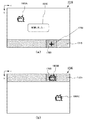
例えば、図18(a),(b)は、仮想空間300内を移動するオブジェクト1800(本図中では1800A,1800B,1800Cの3つ)をタッチペン1790でタッチして捕まえるゲームを表す図である。
For example, FIGS. 18A and 18B are diagrams showing a game in which an object 1800 moving in the virtual space 300 (three
このゲームにおいて、オブジェクト1800Bが周縁領域1715と周縁領域1725を頻繁に行ったり来たりするとき、ユーザが周縁領域1715内の位置を指定すると、CPU 101は、第2表示領域1725側に指示領域1760の形状を拡張する。ポインタ画像1750の位置は第1表示領域1710内にあるものの、指示領域1760は第1表示領域1710だけでなく第2表示領域1720にも拡張される。
In this game, when the
よって、ユーザは、第1表示領域1710の画像が表示される第1のディスプレイ1730上にタッチペン1790を移動させなくても、第2表示領域1720内にのみ存在するオブジェクト1800Bを指す(オブジェクト1800Bを捕獲する)ことができる。ユーザは、タッチペン1790を第1のディスプレイ1730側に持っていったり第2のディスプレイ1740側に持っていったりして繰り返さなければならないような煩わしさが無くなる。
Therefore, the user refers to the
なお、CPU 101は、オブジェクト1800Bがユーザによって選択された旨を示すメッセージ1850を、ポインタ画像1750を表示している第1のディスプレイ1730に表示する。ただし、CPU 101は、メッセージ1850を第2のディスプレイ1740に表示してもよい。
本発明は、上述した実施形態に限定されず、種々の変形及び応用が可能である。また、上述した実施形態の各構成要素を自由に組み合わせることも可能である。 The present invention is not limited to the above-described embodiments, and various modifications and applications are possible. Moreover, it is also possible to freely combine the constituent elements of the above-described embodiments.
図17(a)においては第1表示領域1710と第2表示領域1720は重ならずに互いに接している。しかし、図19に示すように、第1表示領域1910と第2表示領域1920とが重なっていてもよい。
In FIG. 17A, the
また、1つの周縁領域は、表示領域を構成する辺のうちの2つ以上の辺(もしくは辺の一部)に対応付けられていてもよい。図19では、第1表示領域1910は4つの辺1911〜1914で囲まれる領域であり、第2表示領域1920は4つの辺1921〜1924で囲まれる領域である。周縁領域1915は2つの辺1913,1914に対応付けられ、周縁領域1925は2つの辺1921,1922に対応付けられる。第1表示領域1910と第2表示領域1920とが重なる部分にオブジェクト1930が配置されている。
Moreover, one peripheral area | region may be matched with two or more sides (or a part of side) of the sides which comprise a display area. In FIG. 19, the
図20(a)は、図19に示される第1表示領域1910を表す画像の例である。図20(b)は、図19に示される第2表示領域1920を表す画像の例である。オブジェクト1930は、第1表示領域1910と第2表示領域1920の両方に存在する。第1表示領域1910を表す画像は、図17(b)に示す第1のディスプレイ1730に表示され、第2表示領域1920を表す画像は、図17(b)に示す第2のディスプレイ1740に表示される。
FIG. 20A is an example of an image representing the
決定装置200の全部又は一部としてコンピュータを動作させるためのプログラムを、メモリカード、CD−ROM、DVD、MO(Magneto Optical disk)などのコンピュータ読み取り可能な記録媒体に格納して配布し、これを別のコンピュータにインストールし、上述の手段として動作させ、あるいは、上述の工程を実行させてもよい。
A program for operating a computer as all or part of the
さらに、インターネット上のサーバ装置が有するディスク装置等にプログラムを格納しておき、例えば、搬送波に重畳させて、コンピュータにダウンロード等するものとしてもよい。 Furthermore, the program may be stored in a disk device or the like included in a server device on the Internet, and may be downloaded onto a computer by being superimposed on a carrier wave, for example.
以上説明したように、本発明によれば、表示される画面の隅の位置をユーザが指定しやすくするために好適な決定装置、決定方法、ならびに、プログラムを提供することができる。 As described above, according to the present invention, it is possible to provide a determination device, a determination method, and a program suitable for making it easy for the user to specify the positions of the corners of the displayed screen.
100 情報処理装置
101 CPU
102 ROM
103 RAM
104 インターフェース
105 コントローラ
106 外部メモリ
107 DVD−ROMドライブ
108 画像処理部
109 音声処理部
110 NIC
200 決定装置
201 生成部
202A 第1表示部
202B 第2表示部
203 入力受付部
204 決定部
300 仮想空間
310 第1表示領域
311〜314 第1表示領域を構成する辺
320 第2表示領域
321〜324 第2表示領域を構成する辺
330 ポインタ画像
411〜416、421〜426 領域
500 指示領域
511〜514、521〜524 周縁領域
550,550A,550B,550C キャラクタオブジェクト(オブジェクト)
800 画面
810 第1のウインドウ
820 第2のウインドウ
830 第1のディスプレイ
840 第2のディスプレイ
1101 出力部
1200 メッセージ
1310,1330 ポインタ画像
1320,1340 指示領域
1500,1600 画面
1510,1610,1710 第1表示領域
1520,1620,1720 第2表示領域
1515,1525,1615,1625,1715,1725 周縁領域
1530,1630 第1のウインドウ
1540,1640 第2のウインドウ
1550,1570,1650,1670,1750 ポインタ画像
1560,1580,1660,1680,1760 指示領域
1590 第1表示領域と第2表示領域との隙間
1730 第1のディスプレイ
1740 第2のディスプレイ
1790 タッチペン
1800A,1800B,1800C オブジェクト
1850 メッセージ
1910 第1表示領域
1911〜1914 第1表示領域を構成する辺
1915 第1表示領域の周縁領域
1920 第2表示領域
1921〜1924 第2表示領域を構成する辺
1925 第2表示領域の周縁領域
1930 オブジェクト
100
102 ROM
103 RAM
104
200 determining
800
Claims (8)
複数の表示部であって、当該複数の表示部のそれぞれは、前記画像の一部の表示領域を表示する表示部と、
前記画像内の位置を指定する指示入力を前記ユーザから受け付ける入力受付部と、
前記受け付けられた指示入力により指定される位置に対応付けられる指示領域を決定する決定部と、
を備え、
前記決定部は、前記指示入力により指定される位置が、前記複数の表示部により表示される表示領域内に設定される1つ以上の周縁領域のうち
(a)いずれの周縁領域にも含まれない場合、前記指定される位置を含む第1の大きさの領域を当該指示領域として決定し、
(b1)いずれか1つの周縁領域に含まれ、且つ、前記指示入力により指定される位置が含まれる周縁領域に当該オブジェクト画像の位置が含まれる場合、前記指定される位置を含む第2の大きさの領域を当該指示領域として決定し、
(b2)いずれか1つの周縁領域に含まれ、且つ、前記指示入力により指定される位置が含まれる周縁領域に当該オブジェクト画像の位置が含まれない場合、前記指定される位置を含む当該第1の大きさの領域を当該指示領域として決定し、
当該第2の大きさは、当該第1の大きさよりも大きい、
ことを特徴とする決定装置。 A generation unit that generates an image that is an image to be presented to a user and includes an object image selectable by the user ;
A plurality of display units, each of the plurality of display units, a display unit for displaying a display region of a part of the image;
An input receiving unit for receiving an instruction input for designating a position in the image from the user;
A determination unit that determines an instruction area associated with a position specified by the received instruction input;
With
In the determination unit, the position specified by the instruction input is included in any one of the peripheral regions (a) among one or more peripheral regions set in the display region displayed by the plurality of display units. If not, the first size area including the designated position is determined as the designated area,
(B1) contained in one of the peripheral region, and, when said instruction input by Ru include the position of the object image to the periphery region including the position specified, the second containing the position at which the specified Determine the size area as the indicated area,
(B2) If the position of the object image is not included in the peripheral area that is included in any one of the peripheral areas and includes the position specified by the instruction input, the first including the specified position Is determined as the designated area,
The second size is greater than the first size;
A determination device characterized by that.
前記決定部は、前記指示入力により指定される位置が、前記複数の表示部により表示される表示領域内に設定される1つ以上の周縁領域のうち
(a’)いずれの周縁領域にも含まれない場合、前記指定される位置を含む当該第1の大きさと第1の形状とを有する領域を当該指示領域として決定し、
(b1’)いずれか1つの周縁領域に含まれ、且つ、前記指示入力により指定される位置が含まれる周縁領域に当該オブジェクト画像の位置が含まれる場合、前記指定される位置を含む当該第2の大きさと第2の形状とを有する領域を当該指示領域として決定し、
(b2’)いずれか1つの周縁領域に含まれ、且つ、前記指示入力により指定される位置が含まれる周縁領域に当該オブジェクト画像の位置が含まれない場合、前記指定される位置を含む当該第1の大きさと当該第1の形状とを有する領域を当該指示領域として決定する、
ことを特徴とする決定装置。 The determination device according to claim 1,
In the determination unit, the position specified by the instruction input is included in any one of the peripheral regions (a ′) among one or more peripheral regions set in the display region displayed by the plurality of display units. If not, an area having the first size and the first shape including the designated position is determined as the indication area,
(B1 ') is included in one of the peripheral region, and, when the instruction input by Ru include the position of the object image to the periphery region including the position specified, the including the position where the specified first An area having a size of 2 and a second shape is determined as the indicated area;
(B2 ′) If the position of the object image is not included in the peripheral area that is included in any one of the peripheral areas and includes the position specified by the instruction input, the first including the specified position An area having a size of 1 and the first shape is determined as the designated area;
A determination device characterized by that.
前記複数の表示部により表示される表示領域のそれぞれには、当該周縁領域を構成する1つ又は複数の単位領域が設定され、
前記複数の表示部は、互いに隣り合う第1表示部と第2表示部とを有し、
前記決定部は、前記指示入力により指定される位置が、前記第1表示部により表示される表示領域(以下「第1表示領域」という。)の周縁領域を構成する単位領域のうち
(b1’’)前記第2表示部により表示される表示領域(以下「第2表示領域」という。)に隣り合う単位領域に含まれ、且つ、前記指示入力により指定される位置が含まれる周縁領域に当該オブジェクト画像の位置が含まれる場合、当該隣り合う単位領域に当該第2の大きさの当該指示領域を配置し、
(b2’’)前記第2表示領域に隣り合う単位領域に含まれ、且つ、前記指示入力により指定される位置が含まれる周縁領域に当該オブジェクト画像の位置が含まれない場合、当該隣り合う単位領域に当該第1の大きさの当該指示領域を配置する、
ことを特徴とする決定装置。 The determination device according to claim 1 or 2,
In each of the display areas displayed by the plurality of display units, one or more unit areas constituting the peripheral area are set,
The plurality of display units include a first display unit and a second display unit adjacent to each other,
The determination unit is configured such that a position specified by the instruction input is a unit region ( b1 ′ ) that forms a peripheral region of a display region (hereinafter referred to as “first display region”) displayed by the first display unit. ') before Symbol display area (hereinafter to be displayed by the second display unit referred to as "second display region".) included in the unit area adjacent to and, in the peripheral region including the position designated by said instruction input If the object image is Ru contained position, the corresponding instruction region of the second size arranged in the unit area adjacent the,
(B2 ″) If the position of the object image is not included in the peripheral area included in the unit area adjacent to the second display area and including the position specified by the instruction input, the adjacent unit Arranging the designated area of the first size in the area;
A determination device characterized by that.
前記生成される画像には、前記ユーザが選択可能なオブジェクト画像が含まれ、
当該オブジェクト画像と当該指示領域が重なる場合、当該オブジェクト画像を示す情報を選択結果として出力する出力部を更に備える、
ことを特徴とする決定装置。 The determination device according to any one of claims 1 to 3,
The generated image includes an object image selectable by the user,
An output unit that outputs information indicating the object image as a selection result when the object image and the instruction area overlap;
A determination device characterized by that.
前記生成される画像には、前記ユーザによる選択対象を指定するポインタ画像が含まれ、
前記出力部は、前記画像内における当該ポインタ画像の位置が、前記複数の表示部により表示される領域内に設定される1つ以上の周縁領域のうち
(x)いずれの周縁領域にも含まれない場合、当該ポインタ画像を所定の大きさで更に表示し、
(y)いずれか1つの周縁領域に含まれる場合、当該所定の大きさを拡大した当該ポインタ画像を更に表示する、
ことを特徴とする決定装置。 The determination device according to claim 4,
The generated image includes a pointer image that specifies a selection target by the user,
In the output unit, the position of the pointer image in the image is included in any peripheral region ( x ) among one or more peripheral regions set in the region displayed by the plurality of display units. If not, the pointer image is further displayed in a predetermined size,
( Y ) If it is included in any one of the peripheral regions, the pointer image enlarged in the predetermined size is further displayed.
A determination device characterized by that.
前記受け付けられる指示入力に応じて、仮想空間内におけるゲームを進行させるゲーム進行部と、
前記ユーザの当該ゲームの上達度を推定する推定部と、
を更に備える、
ことを特徴とする決定装置。 The determination device according to claim 1,
In response to the accepted instruction input, a game progression unit that advances the game in the virtual space;
An estimation unit for estimating the progress of the user in the game;
In addition Ru equipped with,
A determination device characterized by that.
前記生成部が、ユーザに提示すべき画像であって、前記ユーザが選択可能なオブジェクト画像が含まれる前記画像を生成する生成ステップと、
前記複数の表示部のそれぞれが、前記画像の一部の表示領域を表示する表示ステップと、
前記入力受付部が、前記画像内の位置を指定する指示入力を前記ユーザから受け付ける入力受付ステップと、
前記決定部が、前記受け付けられた指示入力により指定される位置に対応付けられる指示領域を決定する決定ステップと、
を備え、
前記決定ステップでは、前記指示入力により指定される位置が、前記複数の表示部により表示される表示領域内に設定される1つ以上の周縁領域のうち
(a)いずれの周縁領域にも含まれない場合、前記決定部が、前記指定される位置を含む第1の大きさの領域を当該指示領域として決定し、
(b1)いずれか1つの周縁領域に含まれ、且つ、前記指示入力により指定される位置が含まれる周縁領域に当該オブジェクト画像の位置が含まれる場合、前記決定部が、前記指定される位置を含む第2の大きさの領域を当該指示領域として決定し、
(b2)いずれか1つの周縁領域に含まれ、且つ、前記指示入力により指定される位置が含まれる周縁領域に当該オブジェクト画像の位置が含まれない場合、前記指定される位置を含む当該第1の大きさの領域を当該指示領域として決定し、
当該第2の大きさは、当該第1の大きさよりも大きい、
ことを特徴とする決定方法。 A determination method executed by a determination device having a generation unit, a plurality of display units, an input reception unit, and a determination unit,
A generating step for generating the image , which is an image to be presented to a user and includes an object image selectable by the user ;
A display step in which each of the plurality of display units displays a partial display area of the image;
An input receiving step in which the input receiving unit receives an instruction input for designating a position in the image from the user;
A determination step in which the determination unit determines an instruction area associated with a position specified by the received instruction input;
With
In the determining step, the position specified by the instruction input is included in any one of the peripheral areas (a) among one or more peripheral areas set in the display area displayed by the plurality of display units. If not, the determining unit determines the first size area including the designated position as the designated area,
(B1) contained in one of the peripheral region, and a position, when the instruction input by Ru include the position of the object image to the periphery region including the position specified, the determination unit, to the designated A region having a second size including
(B2) If the position of the object image is not included in the peripheral area that is included in any one of the peripheral areas and includes the position specified by the instruction input, the first including the specified position Is determined as the designated area,
The second size is greater than the first size;
A determination method characterized by that.
ユーザに提示すべき画像であって、前記ユーザが選択可能なオブジェクト画像が含まれる前記画像を生成する生成手段、
複数の表示部に、前記画像の一部の表示領域を表示させる表示制御手段、
前記画像内の位置を指定する指示入力を入力部から受け付ける入力受付手段、
前記受け付けられた指示入力に指定される位置に対応付けられる指示領域を決定する決定手段、
として機能させ、
前記決定手段は、前記指示入力により指定される位置が、前記複数の表示部により表示される表示領域内に設定される1つ以上の周縁領域のうち
(a)いずれの周縁領域にも含まれない場合、前記指定される位置を含む第1の大きさの領域を当該指示領域として決定し、
(b1)いずれか1つの周縁領域に含まれ、且つ、前記指示入力により指定される位置が含まれる周縁領域に当該オブジェクト画像の位置が含まれる場合、前記指定される位置を含む第2の大きさの領域を当該指示領域として決定し、
(b2)いずれか1つの周縁領域に含まれ、且つ、前記指示入力により指定される位置が含まれる周縁領域に当該オブジェクト画像の位置が含まれない場合、前記指定される位置を含む当該第1の大きさの領域を当該指示領域として決定し、
当該第2の大きさは、当該第1の大きさよりも大きい、
ことを特徴とするプログラム。
Computer
Generation means for generating an image to be presented to a user, the image including an object image selectable by the user ;
A plurality of display units, display control means for Ru to display part of the display area of the image,
Input receiving means for receiving an instruction input specifying a position in the image from the input unit,
Determining means for determining an instruction area associated with a position specified in the received instruction input;
Function as
In the determination means , the position specified by the instruction input is included in any one of the peripheral areas (a) among one or more peripheral areas set in a display area displayed by the plurality of display units. If not, the first size area including the designated position is determined as the designated area,
(B1) contained in one of the peripheral region, and, when said instruction input by Ru include the position of the object image to the periphery region including the position specified, the second containing the position at which the specified Determine the size area as the indicated area,
(B2) If the position of the object image is not included in the peripheral area that is included in any one of the peripheral areas and includes the position specified by the instruction input, the first including the specified position Is determined as the designated area,
The second size is greater than the first size;
A program characterized by that.
Priority Applications (2)
| Application Number | Priority Date | Filing Date | Title |
|---|---|---|---|
| JP2009029507A JP5430962B2 (en) | 2009-02-12 | 2009-02-12 | Determination apparatus, determination method, and program |
| US12/704,782 US20100201645A1 (en) | 2009-02-12 | 2010-02-12 | Determination apparatus, determination method and data storage medium |
Applications Claiming Priority (1)
| Application Number | Priority Date | Filing Date | Title |
|---|---|---|---|
| JP2009029507A JP5430962B2 (en) | 2009-02-12 | 2009-02-12 | Determination apparatus, determination method, and program |
Publications (2)
| Publication Number | Publication Date |
|---|---|
| JP2010184009A JP2010184009A (en) | 2010-08-26 |
| JP5430962B2 true JP5430962B2 (en) | 2014-03-05 |
Family
ID=42540031
Family Applications (1)
| Application Number | Title | Priority Date | Filing Date |
|---|---|---|---|
| JP2009029507A Active JP5430962B2 (en) | 2009-02-12 | 2009-02-12 | Determination apparatus, determination method, and program |
Country Status (2)
| Country | Link |
|---|---|
| US (1) | US20100201645A1 (en) |
| JP (1) | JP5430962B2 (en) |
Families Citing this family (17)
| Publication number | Priority date | Publication date | Assignee | Title |
|---|---|---|---|---|
| JP4922446B2 (en) * | 2010-09-13 | 2012-04-25 | 株式会社東芝 | Electronic device, control method of electronic device |
| JP5229289B2 (en) | 2010-09-24 | 2013-07-03 | 日本電気株式会社 | Display device, coordinate notification method and program |
| GB2485842A (en) | 2010-11-29 | 2012-05-30 | Nec Casio Mobile Comm Ltd | Touch-sensitive electronic device with a plurality of touch screens |
| JP5846738B2 (en) | 2011-01-06 | 2016-01-20 | 任天堂株式会社 | Display control program, display device, display system, and display control method |
| KR101883354B1 (en) * | 2011-05-30 | 2018-07-30 | 삼성전자주식회사 | Apparatus and method for browsing electronic maps in device with touch screen |
| JP6117470B2 (en) * | 2011-12-20 | 2017-04-19 | セイコーエプソン株式会社 | Display device, projector, image display method, and display system |
| KR20130130453A (en) * | 2012-05-22 | 2013-12-02 | 엘지전자 주식회사 | Image display apparatus and operating method for the same |
| TWI470598B (en) * | 2012-08-07 | 2015-01-21 | Wistron Corp | Method for adjusting display and computer program product thereof |
| JP6055277B2 (en) * | 2012-11-06 | 2016-12-27 | 川崎重工業株式会社 | Vehicle meter display device |
| US9075494B2 (en) * | 2013-02-01 | 2015-07-07 | Cyberlink Corp. | Systems and methods for performing object selection |
| US10275933B2 (en) * | 2013-05-24 | 2019-04-30 | Thomson Licensing | Method and apparatus for rendering object for multiple 3D displays |
| CN106850719B (en) * | 2015-12-04 | 2021-02-05 | 珠海金山办公软件有限公司 | Data transmission method and device |
| JP6432583B2 (en) * | 2016-10-28 | 2018-12-05 | セイコーエプソン株式会社 | Display device, head-mounted display device, and display device control method |
| GB201709199D0 (en) * | 2017-06-09 | 2017-07-26 | Delamont Dean Lindsay | IR mixed reality and augmented reality gaming system |
| WO2019066678A1 (en) * | 2017-09-29 | 2019-04-04 | Ringcentral, Inc. (A Delaware Corporation) | Systems and methods for enabling participants in an audio or video conference session |
| JP7292024B2 (en) * | 2018-10-22 | 2023-06-16 | キヤノン株式会社 | Information processing device, control method for information processing device, computer program |
| CN109876433B (en) * | 2019-03-28 | 2020-09-18 | 瑞声科技(新加坡)有限公司 | Position prompting method of game role, terminal device and storage medium |
Family Cites Families (12)
| Publication number | Priority date | Publication date | Assignee | Title |
|---|---|---|---|---|
| JPH0816353A (en) * | 1994-06-28 | 1996-01-19 | Sharp Corp | Object display enlarging method |
| JP3095685B2 (en) * | 1996-05-27 | 2000-10-10 | 株式会社ナムコ | Shooting type game device and screen determination method |
| JPH10161835A (en) * | 1996-12-02 | 1998-06-19 | Hitachi Ltd | Overlap display method and multi-screen system |
| US6081267A (en) * | 1998-11-19 | 2000-06-27 | Columbia Scientific Incorporated | Computerized apparatus and method for displaying X-rays and the like for radiological analysis and manipulation and transmission of data |
| JP2000284941A (en) * | 1999-03-31 | 2000-10-13 | Mitsubishi Electric Corp | Cursor display device for multi-display system |
| JP4675498B2 (en) * | 2001-04-25 | 2011-04-20 | 株式会社バンダイナムコゲームス | Image processing apparatus, image processing program, and recording medium recording the program |
| JP3708535B2 (en) * | 2004-03-12 | 2005-10-19 | コナミ株式会社 | Shooting game equipment |
| US7525511B2 (en) * | 2004-07-02 | 2009-04-28 | Microsoft Corporation | System and method for determining display differences between monitors on multi-monitor computer systems |
| JP2006254979A (en) * | 2005-03-15 | 2006-09-28 | Namco Bandai Games Inc | Game system, game terminal, server, program and information storage medium |
| JP4405430B2 (en) * | 2005-05-12 | 2010-01-27 | 任天堂株式会社 | GAME PROGRAM AND GAME DEVICE |
| JP2007111318A (en) * | 2005-10-21 | 2007-05-10 | Sony Computer Entertainment Inc | Game control method, program and game apparatus |
| JP4464948B2 (en) * | 2006-10-13 | 2010-05-19 | 株式会社日立製作所 | Projection display system |
-
2009
- 2009-02-12 JP JP2009029507A patent/JP5430962B2/en active Active
-
2010
- 2010-02-12 US US12/704,782 patent/US20100201645A1/en not_active Abandoned
Also Published As
| Publication number | Publication date |
|---|---|
| US20100201645A1 (en) | 2010-08-12 |
| JP2010184009A (en) | 2010-08-26 |
Similar Documents
| Publication | Publication Date | Title |
|---|---|---|
| JP5430962B2 (en) | Determination apparatus, determination method, and program | |
| JP5462828B2 (en) | Selection device, selection method, and program | |
| JP5831562B2 (en) | Image processing apparatus and method | |
| JP3961545B2 (en) | Object selection device, object selection method, and program | |
| US8172681B2 (en) | Storage medium having stored therein game program and game device | |
| JP5576061B2 (en) | Program and game device | |
| JP4376292B2 (en) | Instruction content determination apparatus, instruction content determination method, and program | |
| JP2008250813A (en) | Image creating device, image processing method, and program | |
| JP2006102275A (en) | Game system, program and information storage medium | |
| JP5406818B2 (en) | GAME DEVICE, GAME DEVICE CONTROL METHOD, AND PROGRAM | |
| JP2007257262A (en) | Image generation device, image generation method, and program | |
| JP4881981B2 (en) | Virtual space display device, viewpoint setting method, and program | |
| JP5351674B2 (en) | GAME DEVICE, GAME CONTROL METHOD, AND PROGRAM | |
| JP5209654B2 (en) | Display device, display method, and program | |
| JP5124545B2 (en) | GAME DEVICE, GAME PROCESSING METHOD, AND PROGRAM | |
| JP5177453B2 (en) | GAME DEVICE, GAME PROCESSING METHOD, AND PROGRAM | |
| JP5401380B2 (en) | Processing device, processing method, and program | |
| JP5155427B2 (en) | GAME DEVICE, GAME DEVICE CONTROL METHOD, AND PROGRAM | |
| JP5138669B2 (en) | Selection device, selection method, and program | |
| JP5143805B2 (en) | Image processing apparatus, processing method, and program | |
| JP2013065328A (en) | Selection device, selection method, and program | |
| JP2000167241A (en) | Video game machine having feature in function for displaying attention pattern on game video generated by three-dimensional computer graphics, and program storage medium |
Legal Events
| Date | Code | Title | Description |
|---|---|---|---|
| A621 | Written request for application examination |
Free format text: JAPANESE INTERMEDIATE CODE: A621 Effective date: 20110428 |
|
| A131 | Notification of reasons for refusal |
Free format text: JAPANESE INTERMEDIATE CODE: A131 Effective date: 20130219 |
|
| A521 | Request for written amendment filed |
Free format text: JAPANESE INTERMEDIATE CODE: A523 Effective date: 20130409 |
|
| TRDD | Decision of grant or rejection written | ||
| A01 | Written decision to grant a patent or to grant a registration (utility model) |
Free format text: JAPANESE INTERMEDIATE CODE: A01 Effective date: 20131203 |
|
| A61 | First payment of annual fees (during grant procedure) |
Free format text: JAPANESE INTERMEDIATE CODE: A61 Effective date: 20131204 |
|
| R150 | Certificate of patent or registration of utility model |
Free format text: JAPANESE INTERMEDIATE CODE: R150 Ref document number: 5430962 Country of ref document: JP Free format text: JAPANESE INTERMEDIATE CODE: R150 |
|
| R250 | Receipt of annual fees |
Free format text: JAPANESE INTERMEDIATE CODE: R250 |
|
| R250 | Receipt of annual fees |
Free format text: JAPANESE INTERMEDIATE CODE: R250 |
|
| R250 | Receipt of annual fees |
Free format text: JAPANESE INTERMEDIATE CODE: R250 |
|
| R250 | Receipt of annual fees |
Free format text: JAPANESE INTERMEDIATE CODE: R250 |
|
| S531 | Written request for registration of change of domicile |
Free format text: JAPANESE INTERMEDIATE CODE: R313531 |
|
| R350 | Written notification of registration of transfer |
Free format text: JAPANESE INTERMEDIATE CODE: R350 |
|
| R250 | Receipt of annual fees |
Free format text: JAPANESE INTERMEDIATE CODE: R250 |
|
| R250 | Receipt of annual fees |
Free format text: JAPANESE INTERMEDIATE CODE: R250 |
|
| R250 | Receipt of annual fees |
Free format text: JAPANESE INTERMEDIATE CODE: R250 |
|
| R250 | Receipt of annual fees |
Free format text: JAPANESE INTERMEDIATE CODE: R250 |