JP5430211B2 - Drive motor - Google Patents
Drive motor Download PDFInfo
- Publication number
- JP5430211B2 JP5430211B2 JP2009105472A JP2009105472A JP5430211B2 JP 5430211 B2 JP5430211 B2 JP 5430211B2 JP 2009105472 A JP2009105472 A JP 2009105472A JP 2009105472 A JP2009105472 A JP 2009105472A JP 5430211 B2 JP5430211 B2 JP 5430211B2
- Authority
- JP
- Japan
- Prior art keywords
- housing
- control board
- drive motor
- rotating shaft
- stator assembly
- Prior art date
- Legal status (The legal status is an assumption and is not a legal conclusion. Google has not performed a legal analysis and makes no representation as to the accuracy of the status listed.)
- Active
Links
Images


Description
この発明は、例えば送風ユニットのブロワケース等の空気が流れる通路を有するケースに収納されてファン等の所定の空調機器を駆動するためのモータに関し、特にこの駆動モータのハウジングに関する。 The present invention relates to a motor that is housed in a case having a passage through which air flows, such as a blower case of a blower unit, for example, and more particularly to a housing of the drive motor.
近年においては、車両用空調装置やハイブリッド車向け換気装置の送風機用駆動モータとして、従来品よりも小型でありながら高性能なものが必要となっており、これに伴い、防水性、放熱性に優れ、且つ送風機の回転軸の軸方向に沿った寸法を小さくし、しかも製造コストの抑制も図られた駆動モータの開発が要請されている。 In recent years, as a drive motor for a blower of a vehicle air conditioner or a hybrid vehicle ventilation system, it is necessary to have a smaller but higher performance than conventional products. There is a demand for the development of a drive motor that is excellent and that has a reduced size along the axial direction of the rotating shaft of the blower and that is also capable of reducing manufacturing costs.
この点、例えば特許文献1に示されるようなブラシレスモータを備えた車載用送風機が既に公知になっている。この特許文献1に示される車載用送風機は、送風ファンを回転させるブラシレスモータと、前記ブラシレスモータの金属製のハウジングに一体的に形成された冷却フィンと、当該冷却フィンの周囲に空気流を生じさせるべく前記送風ファンに設けられた補助ブレードと、前記ハウジングに密着して取付けられた駆動素子とを備えたもので、モータ用の駆動素子の冷却能力を高め、送風機の高さ方向の寸法を縮小すると共に、部品点数を削減して製造コストの削減を図ることを課題としている。 In this regard, for example, an in-vehicle blower including a brushless motor as disclosed in Patent Document 1 has already been publicly known. The on-vehicle blower disclosed in Patent Document 1 generates a brushless motor that rotates a blower fan, cooling fins that are integrally formed on a metal housing of the brushless motor, and an air flow around the cooling fins. The auxiliary blade provided on the blower fan and the drive element attached in close contact with the housing to increase the cooling capacity of the drive element for the motor, and the height of the blower It is an object to reduce the manufacturing cost by reducing the number of parts while reducing the size.
しかしながら、特許文献1に示される車載用送風機のブラシレスモータでは、制御回路基板を防水構造にするために、アッパーケースより上側のスクロール室内とは別に、制御回路基板を収納するようにアッパーケースの下側にロアーケースを備えて制御回路基板収納室を設け、また制御回路基板の放熱用に冷却フィンを設けているので、実際にはブラシレスモータ、ひいては送風機が相対的に大型化し、また、冷却フィンを有する分、構造が複雑化し、ブラシレスモータの製造コストも相対的に高くなっているという不具合を有している。 However, in the brushless motor of the in-vehicle blower disclosed in Patent Document 1, in order to make the control circuit board waterproof, the lower part of the upper case is placed so as to accommodate the control circuit board separately from the scroll chamber above the upper case. Since the control circuit board storage chamber is provided with a lower case on the side, and cooling fins are provided for heat dissipation of the control circuit board, the brushless motor and the blower are actually relatively large, and the cooling fins As a result, the structure is complicated, and the manufacturing cost of the brushless motor is relatively high.
そこで、本発明は、簡易な構造でありながら防水性、放熱性に優れていると共に、駆動モータへの薄型化の要請にも応え、更にその製造コストの削減も図った駆動モータを提供することを目的とする。 Accordingly, the present invention provides a drive motor that has a simple structure and is excellent in waterproofness and heat dissipation, meets the demand for a thinner drive motor, and further reduces its manufacturing cost. With the goal.
この発明に係る駆動モータは、ファン等の被回転部材を長手方向に沿った方向のうち一方の端部に取り付けて回転させる回転軸と、前記回転軸に取り付けられてこの回転軸と共に回転することが可能であるロータアセンブリと、前記ロータアセンブリに対し前記回転軸の径方向に沿った方向にて対向し、且つ前記回転軸と共に回転しないように配置されたステータアセンブリと、前記ステータアセンブリよりも前記回転軸の軸方向に沿った方向のうち前記一方の端部側に近接する位置に設けられた制御基板と、前記回転軸の長手方向に沿った方向のうち前記制御基板よりも一方の端部側の位置にて前記回転軸の径方向に沿って外方に延出して、前記制御基板、前記ロータアセンブリ、及び前記ステータアセンブリを内包するように形成されたハウジングと、によってモータ本体部を形成し、前記ハウジングを、金属で形成すると共に、送風路が内部に画成されたケースに対して前記送風路にその外面が表出した状態となるように取り付け、前記ハウジングに内包された前記ステータアセンブリを、このハウジングの内側面に固定したことを特徴としている(請求項1)。ここで、送風路が内部に画成されたケースとは、例えばブロワケース等が挙げられる。また、ステータアセンブリは、ロータアセンブリに対し回転軸の径方向に沿った方向であればロータアセンブリの内周側のみならず外周側に配置された構成でも良い。 The drive motor according to the present invention is configured to attach a rotating member such as a fan to one end of a direction along the longitudinal direction and rotate the rotating shaft, and to rotate with the rotating shaft attached to the rotating shaft. A rotor assembly that is configured to face the rotor assembly in a direction along a radial direction of the rotating shaft, and disposed so as not to rotate with the rotating shaft; A control board provided at a position close to the one end side in a direction along the axial direction of the rotation shaft, and one end portion of the control board in a direction along the longitudinal direction of the rotation shaft. The control board, the rotor assembly, and the stator assembly are formed so as to extend outward along the radial direction of the rotating shaft at a side position. A motor body is formed by winging, and the housing is formed of metal, and attached to a case in which the air passage is defined inside, so that the outer surface of the air passage is exposed to the air passage. The stator assembly contained in the housing is fixed to the inner surface of the housing (claim 1). Here, examples of the case in which the air passage is defined inside include a blower case. Further, the stator assembly may be arranged on the outer peripheral side as well as the inner peripheral side of the rotor assembly as long as it is in the radial direction of the rotating shaft with respect to the rotor assembly.
これにより、制御基板、ロータアセンブリ、及びステータアセンブリを内包する金属製のハウジングがこれらの制御基板、ロータアセンブリ、ステータアセンブリを上方から傘状に覆うので、制御基板に対して防水機能を持たせることが可能となり、制御基板を収納するための制御基板収納室を特別に設ける必要がなくなる。しかも、熱伝導性に優れた金属製であると共にその外面をブロワケース等のケースの送風路に表出させたハウジング内に、制御基板、ロータアセンブリ、及びステータアセンブリ等のモータ本体部を構成する全ての部品がまとまっているため、ハウジングの内面に固定されたステータアセンブリからの熱がハウジングに伝わり、制御基板からの熱もハウジングに伝わるところ、ハウジングの外面がケースの送風路に面しているので、ステータアセンブリや制御基板からの発熱に対しハウジングの外面から放熱させることが可能である。また、ハウジングに制御基板、ロータアセンブリ、及びステータアセンブリをコンパクトに内包しているので、駆動モータに対し回転軸の軸方向に沿った方向での厚みを薄くして小型化を図ることもできる。 As a result, a metal housing that encloses the control board, the rotor assembly, and the stator assembly covers the control board, the rotor assembly, and the stator assembly in an umbrella shape from above, so that the control board has a waterproof function. This eliminates the need for a special control board storage chamber for storing the control board. In addition, a motor body such as a control board, a rotor assembly, and a stator assembly is formed in a housing that is made of metal having excellent thermal conductivity and whose outer surface is exposed to a blower passage of a case such as a blower case. Since all the parts are gathered, heat from the stator assembly fixed to the inner surface of the housing is transferred to the housing, and heat from the control board is also transferred to the housing, and the outer surface of the housing faces the air passage of the case Therefore, it is possible to dissipate heat from the outer surface of the housing against heat generated from the stator assembly and the control board. Further, since the control board, the rotor assembly, and the stator assembly are contained in the housing in a compact manner, it is possible to reduce the thickness by reducing the thickness in the direction along the axial direction of the rotation shaft with respect to the drive motor.
しかも、この制御基板のハウジング側となる上面にトランジスタを配置することにより、ハウジング内に内包された部材の中でも相対的に発熱量の大きい制御基板及びトランジスタをハウジングのうちの送風路内により突出した部分に配置することができるので、制御基板とトランジスタとに対する放熱効果をより促進させることが可能となる。 Moreover, by arranging the transistor on the upper surface of the control board on the housing side, the control board and the transistor having a relatively large heat generation among the members contained in the housing are protruded into the blower passage of the housing. Since it can arrange | position in a part, it becomes possible to further promote the thermal radiation effect with respect to a control board | substrate and a transistor.
そして、この発明に係る駆動モータでは、前記モータ本体部は、前記ハウジングの前記回転軸の軸方向に沿った側のうち前記制御基板とは反対側の端面に設けられたフランジを介して前記ケースに取り付けられるようになっており、前記ハウジングと前記フランジとの間に弾性部材を介在させた構成となっている(請求項2)。 And in the drive motor which concerns on this invention, the said motor main-body part is the said case via the flange provided in the end surface on the opposite side to the said control board among the sides along the axial direction of the said rotating shaft of the said housing. And is configured such that an elastic member is interposed between the housing and the flange.
これにより、弾性部材でハウジングとフランジとの隙間がシールされて、ハウジングとフランジとの隙間から水が浸入するのを抑止することができ、これに伴い、防水用のシール部材の取り付けを不要とすることができる。また、ハウジングに収納されたロータ等で発生する磁気振動が弾性部材により遮断されてフランジに伝達され難くなるので、駆動モータの低騒音化を図ることができる。 As a result, the gap between the housing and the flange is sealed by the elastic member, and water can be prevented from entering through the gap between the housing and the flange. Accordingly, it is not necessary to attach a waterproof seal member. can do. In addition, since the magnetic vibration generated by the rotor or the like housed in the housing is blocked by the elastic member and is not easily transmitted to the flange, it is possible to reduce the noise of the drive motor.
更に、この発明に係る駆動モータでは、前記弾性部材のうち前記ハウジングの基端側と対向する部分は複数の条状の凹凸を有するものとなっている(請求項3)。これにより、弾性部材の振動吸収効果が高められるので、駆動モータについて、より一層の低騒音化を図ることができる。 Furthermore, in the drive motor according to the present invention, a portion of the elastic member that faces the base end side of the housing has a plurality of strip-shaped irregularities (claim 3). Thereby, since the vibration absorption effect of the elastic member is enhanced, it is possible to further reduce the noise of the drive motor.
以上のように、これらの発明によれば、制御基板、ロータアセンブリ、及びステータアセンブリを内包する金属製のハウジングがこれらの制御基板、ロータアセンブリ、ステータアセンブリを上方から傘状に覆うので、制御基板に対して防水機能を持たせることが可能となり、制御基板を収納するための制御基板収納室を特別に設ける必要がなくなる。しかも、熱伝導性に優れた金属製であると共にその外面をブロワケース等のケースの送風路に表出させたハウジング内に、制御基板、ロータアセンブリ、及びステータアセンブリ等のモータ本体部を構成する全ての部品がまとまっているため、ステータアセンブリからの熱がハウジングに伝わり、制御基板からの熱もハウジングに伝わるところ、ハウジングの外面がケースの送風路に面しているので、ステータアセンブリや制御基板からの発熱に対しハウジングの外面から放熱することが可能であるので、駆動モータ全体の温度の低下を促進させることができることから、ヒートシンク等の放熱装置を不要とし、駆動モータについて放熱性の維持・向上を図りつつ小型化とその製造コストの削減を図ることが可能となる。 As described above, according to these inventions, the metal housing that encloses the control board, the rotor assembly, and the stator assembly covers the control board, the rotor assembly, and the stator assembly in an umbrella shape from above. Therefore, it is possible to provide a waterproof function, and it is not necessary to provide a control board storage chamber for storing the control board. In addition, a motor body such as a control board, a rotor assembly, and a stator assembly is formed in a housing that is made of metal having excellent thermal conductivity and whose outer surface is exposed to a blower passage of a case such as a blower case. Since all the parts are gathered, the heat from the stator assembly is transferred to the housing, and the heat from the control board is also transferred to the housing. Since the outer surface of the housing faces the air passage of the case, the stator assembly and the control board Because it is possible to dissipate heat from the outer surface of the housing against heat generated from the housing, it is possible to promote a decrease in the temperature of the entire drive motor. It is possible to reduce the size and manufacturing cost while improving.
また、これらの発明によれば、ハウジングに制御基板、ロータアセンブリ、及びステータアセンブリが内包されているので、駆動モータに対し回転軸の軸方向に沿った方向での厚みの薄型化を図ることが可能となる。 According to these inventions, since the control board, the rotor assembly, and the stator assembly are included in the housing, it is possible to reduce the thickness of the drive motor in the direction along the axial direction of the rotation shaft. It becomes possible.
更に、これらの発明によれば、ハウジングに内包された制御基板、ロータアセンブリ、及びステータアセンブリの中でも相対的に発熱量の大きな制御基板をハウジングのうちの送風路内により突出した部分に配置することができるので、制御基板に対する放熱効果をより促進させることが可能となる。しかも、トランジスタをこの制御基板のハウジング側となる上面に配置することで、トランジスタに対する放熱効果をより促進させることも可能となる。そして、インナーロータ型、アウターロータ型のいずれの駆動モータにもこの発明の構成を適用することができる。 Furthermore, according to these inventions, among the control board, the rotor assembly, and the stator assembly contained in the housing, the control board having a relatively large heat generation amount is disposed in a portion of the housing that protrudes further in the air passage. Therefore, the heat dissipation effect on the control board can be further promoted. In addition, by disposing the transistor on the upper surface of the control board on the housing side, it is possible to further promote the heat dissipation effect on the transistor. The configuration of the present invention can be applied to both inner rotor type and outer rotor type drive motors.
特に請求項2に記載の発明によれば、弾性部材でハウジングとフランジとの隙間がシールされて、ハウジングとフランジとの隙間から水が浸入するのを抑止することができ、これに伴い、防水用のシール部材の取り付けを不要とすることができる。また、ハウジングに収納されたロータ等で発生する磁気振動が弾性部材により遮断されてフランジに伝達され難くなるので、駆動モータの低騒音化を図ることができる。 In particular, according to the second aspect of the present invention, the gap between the housing and the flange is sealed by the elastic member, so that water can be prevented from entering through the gap between the housing and the flange. Therefore, it is possible to eliminate the need for attaching a sealing member. In addition, since the magnetic vibration generated by the rotor or the like housed in the housing is blocked by the elastic member and is not easily transmitted to the flange, it is possible to reduce the noise of the drive motor.
特に請求項3に記載の発明によれば、弾性部材について振動吸収効果が高められるので、駆動モータのより一層の低騒音化を図ることができる。 In particular, according to the third aspect of the present invention, the vibration absorbing effect of the elastic member is enhanced, so that the noise of the drive motor can be further reduced.
以下、この発明の実施形態について添付図面を参照しながら説明する。 Embodiments of the present invention will be described below with reference to the accompanying drawings.
図1において、送風ユニット1は、例えば、図示しないバッテリーを冷却するためにバッテリーの下流側に配置され、バッテリーにより暖められた空気を吸引して排出するために用いられるもので、スクロール状のブロワケース2と、駆動モータ3と、多羽翼ファン4とを有して構成されている。
In FIG. 1, a blower unit 1 is disposed on the downstream side of a battery, for example, to cool a battery (not shown), and is used to suck and discharge air warmed by the battery. It has a
ブロワケース2は、樹脂等により構成され、ベルマウス5が一体又は別体に設けられた開口部6を有する上側壁7と、この上側壁7に対し所定の間隔を開けて対向するかたちで配置され、駆動モータ3を取り付けるモータ挿入孔8が形成された下側壁9と、これら上側壁7と下側壁9との外周縁を結ぶように吐出口20を残すかたちで設けられた外周壁10とを有して構成されている。外周壁10は、巻始部10aを起点として、ここから多羽翼ファン4の周方向に沿いつつ当該多羽翼ファン4の中心からの距離が徐々に大きくなる渦巻き状に形成されている。
The
多羽翼ファン4は、それ自体は公知のもので、駆動モータ3の下記する回転軸11に固定されるボス部12と、このボス部12に連接されるコーン部13と、回転軸11の軸方向に沿って立設されると共にコーン部13の外周縁の円周方向に沿って設けられた複数の羽根14とを具備するもので、これらの羽根14により画成された、コーン部13と対峙する吸込口15から流入された空気をコーン部13に沿って羽根14側に導き、羽根14と羽根14との間を通過させる構成となっている。
The
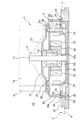
駆動モータ3は、図2にも示されるように、回転軸11と、ボス部31bと、ボス部31bの外周面に装着されたステータアセンブリ22と、制御基板28と、ロータアセンブリ21と、ハウジング31とによりモータ本体部30を形成したものとなっている。
As shown in FIG. 2, the
このうち、回転軸11は、略円棒形状を成すもので、多羽翼ファン4等の被回転部材を長手方向の上端部側となる一方側端に取り付けることにより、多羽翼ファン4等の被回転部材を回転可能としている。そして、回転軸11は、下記するハウジング31から回転軸11の軸方向に沿って下方に延びる円筒状のボス部31bに軸受23、24を介して回転可能に支承されている。
Among these, the rotating
また、ボス部31bの回転軸11の軸方向に沿って延びる外周面のうち下方側には、ステータアセンブリ22が配置されている。このステータアセンブリ22は、鉄製のコア26と、このコア26の側方外周面に複数回にわたって巻回された電機子巻線25とにより構成されている。そして、ステータアセンブリ22は、ボス部31bを介して、ハウジング31の内側面に固定されている。
The
更に、回転軸11は、ステータアセンブリ22よりも回転軸11の軸方向の下方においてロータアセンブリ21が取り付けられている。このロータアセンブリ21は、ステータアセンブリ22に対して回転軸11の径方向に沿った方向にて対向した位置にあり、ヨーク29と、このヨーク29に対し電機子巻線25と対峙するようにその内側面に設けられたマグネット27とにより構成されている。
Further, the
このような構成とすることにより、駆動モータ3は、ステータアセンブリ22によって生ずる回転磁界でロータアセンブリ21を回転させ、このロータアセンブリ21の回転で更に回転軸11を回転させるものとなっている。
With such a configuration, the
更にまた、駆動モータ3は、ステータアセンブリ22の電機子巻線25に給電される電流を電子スイッチで切り替える等の制御を行う電子部品が配設された制御基板28を有しており、この制御基板28は、ステータアセンブリ22及びロータアセンブリ21よりも回転軸11の軸方向に沿った方向のうち上端部側に配置されている。
Furthermore, the
そして、駆動モータ3は、回転軸11の長手方向に沿った方向のうち制御基板28よりも上端部側の位置にて回転軸11の径方向に沿って外方に延出した後に回転軸11の軸方向に略沿って延びることにより傘状に形成されたハウジング本体31aと、このハウジング本体31aの略中央から回転軸11の軸方向に沿って延びる円筒状のボス部31bと、ハウジング本体31aの内面のうち外縁近傍部位から回転軸11の軸方向に沿って下方に延びるボス部31cとを有して構成されるハウジング31を有している。
The
これにより、ハウジング31は、傘状に形成されたハウジング本体31aにより、制御基板28、ステータアセンブリ22、及びロータアセンブリ21等のモータ本体部30を構成する全ての部品を内包したものとなっていると共に、上述のようにボス部31bにて軸受23、24を介して回転軸11を回転可能に支承し、更に、制御基板28の孔とボス部31cの孔とを連通させて、スクリュー39をこれらの制御基板28とボス部31cとの孔に挿入・螺合させることにより制御基板28がハウジング31に取り付けられるようになっている。しかも、制御基板28は、ステータアセンブリ22及びロータアセンブリ21よりも回転軸11の軸方向に沿った方向のうちハウジング31のハウジング本体31a側に近接して配置されている。
Accordingly, the
また、制御基板28の上面にはトランジスタ37が配置されている。このトランジスタ37の周囲にはシリコングリス38が塗布されており、このシリコングリス38を通じてトランジスタ37の熱をハウジング31のハウジング本体31aに伝えて放熱できるようになっている。
A
そして、モータ本体部30のハウジング31内のうち開口側となる下端部側(回転軸11が突設された側と反対側)には、ブロワケース2に駆動モータ3を取り付けるために、例えば樹脂製のフランジ32が取り付けられている。
In order to attach the
また、多羽翼ファン4について、その吸込口15がブロワケース2の開口部6に近接するように当該ブロワケース2に収納すると共に、駆動モータ3について、そのモータ本体部30がブロワケース2の内部に突出するようにブロワケース2の下側壁9にフランジ32を介して取り付けることにより、図1に示されるように、モータ本体部30のブロワケース2内に突出した部分の側面と、多羽翼ファン4の外周及びブロワケース2の内面とにより、多羽翼ファン4の羽根間から回転軸11の径方向外側に送出された空気を吐出口20に向けて圧送するスクロール状の送風路40が画成されている。
The
すなわち、送風ユニット1自体の回転軸11の軸方向に沿った寸法(H)が従来の送風ユニットと同じであると設定すると、ブロワケース2の下側壁9が、モータ本体部30の下端に設けられたフランジ32に当接するように外周壁10の回転軸11の軸方向に沿った寸法が従来よりも大きくなり、送風路40がモータ本体部30の下端に設けられたフランジ32に至るまで拡大している。このため、従来においては、制御基板等が内包されたモータ本体部がブロワケースの外側に配置されて、モータ本体部の周囲がデッドスペースとなってしまい有効利用されなかったのに対し、本構成においては、モータ本体部30の周囲を送風路40として用いられるようになっている。
That is, if the dimension (H) along the axial direction of the
ところで、駆動モータ3のモータ本体部30のハウジング31は、上記構成により、図1(b)及び図2に示されるように、上記のように従来よりも拡大された送風路40にその外面が表出したものとなっており、更に、このハウジング31は、熱伝導性に優れた素材、例えばアルミニウム等の金属を素材として形成されている。尚、ブロワケース2は、複数のケース部材を固定具で連結することにより構成されるものであっても良い。
By the way, the
しかるに、このようなモータ本体部30のハウジング31の配置及び構成とすることにより、ハウジング31に内包された制御基板28、ステータアセンブリ22が発熱してもハウジング31のハウジング本体31の外面(特にその側方外面)が送風路40に表出しているため、これらの制御基板28やステータアセンブリ22から生ずる熱が熱伝導性の高いハウジング31に伝達され、更に、ハウジング31のハウジング本体31aの外面から放熱することができるので、ヒートシンク等の放熱装置を用いなくても簡易な構造で駆動モータ3の放熱が可能となる。これに伴い、部品点数の削減による送風ユニット1の相対的な製造コストの削減、駆動モータ3ひいては送風ユニット1の更なる小型化を図ることができる。
However, with the arrangement and configuration of the
そして、制御基板28からの発熱、特にトランジスタ37の熱はこのトランジスタ37の周囲に塗布されたシリコングリス38が近接したハウジング31との間を埋めるように設けられているのでハウジング31を介して外部(送風路40)への放熱が可能となっている。また電機子巻25を流れる電流により発生した熱も、鉄製のコア26を通じてハウジング31のボス部31cに伝えられるので、ハウジング31を介して外部(送風路40)への放熱が可能となっている。またロータアセンブリ21によりハウジング31内の空気が攪拌されるため、ハウジング31内に格納された発熱部品の放熱にとって都合が良い。
The heat generated from the
しかも、制御基板28は、この実施例では、ハウジング31内においてステータアセンブリ22及びロータアセンブリ21よりも多羽翼ファン4側に配置されており、これにより、他の機器よりもハウジング31により近く、しかも、ハウジング31のうち多羽翼ファン4による空気の流れが大きい側に近接して位置しているので、ハウジング31を介しての放熱効果をより良く得ることができる。
Moreover, in this embodiment, the
また、この駆動モータ3は、図2及び図3に示されるように、ハウジング31とフランジ32との間に弾性部材33を介在させている。この弾性部材33は環状をなしていると共にフランジ32に対しその厚み方向に沿って延びる係合孔36に係合することで、フランジ32に固定されるための差し込み部35を有している。そして、ハウジング31とフランジ32との固定は、図3に示される複数の貫通孔41に、ねじ類(図示せず)を貫通させるとともにハウジング31に設けたねじ受孔(図示せず)に取付けるなど、周知の手段により行われる。このように、ハウジング31とフランジ32との間に弾性部材33を介在させることによって、ハウジング31に収納されたロータアセンブリ21等で発生する磁気振動が弾性部材33により遮断されてフランジ32に伝達され難くなるので、駆動モータ3の低騒音化を図ることができる。また、弾性部材33がハウジング31とフランジ32との隙間から水が浸入するのを抑止する機能も兼ねるので、防水用のシール部材の取り付けを不要とすることができる。なお、弾性部材33は、例えばEPDP(エチレン−プロピレン−ジエンゴム)、ブチルゴム、エラストマーと称される高分子化合物など、車両用空調装置に一般的に用いられている素材で構成される。
Further, the
そして、弾性部材33は、図2及び図3に示されるように、その環状部分において、その環の中心方向に向かって延びる複数の凹部34を有しており、この凹部34は、図2に示されるように、弾性部材33の環状部分の径方向外縁まで達していなくても良い。これにより、ハウジング31はフランジ32に対してフローティング的な状態となり、弾性部材33の振動吸収効果が高められるので、駆動モータ3についてより一層の低騒音化を図ることができる。
As shown in FIGS. 2 and 3, the
なお、発明の実施形態について、これまでステータアセンブリの外周をロータアセンブリが回転するアウターロータ型のモータを例に説明してきたが、当然ながら、本発明を、ステータアセンブリの内周側をロータアセンブリが回転するインナーロータ型のモータに適用することも可能である。 Although the embodiment of the invention has been described by taking an outer rotor type motor in which the rotor assembly rotates on the outer periphery of the stator assembly as an example, it should be understood that the rotor assembly is disposed on the inner periphery side of the stator assembly. It is also possible to apply to a rotating inner rotor type motor.
1 送風ユニット
2 ブロワケース
3 駆動モータ
4 多羽翼ファン
11 回転軸
21 ロータアセンブリ
22 ステータアセンブリ
23 軸受
24 軸受
25 電機子巻線
27 マグネット
28 制御基板
30 モータ本体部
31 ハウジング
31a ハウジング本体
31b ボス部
32 フランジ
33 弾性部材
34 凹部
35 差し込み部
36 係合孔
40 送風路
41 貫通孔
DESCRIPTION OF SYMBOLS 1
Claims (3)
前記ハウジングを、金属で形成すると共に、送風路が内部に画成されたケースに対して前記送風路にその外面が表出した状態となるように取り付け、前記ハウジングに内包された前記ステータアセンブリを、このハウジングの内側面に固定したことを特徴とする駆動モータ。 A rotating shaft for rotating a rotating member such as a fan attached to one end of a direction along the longitudinal direction, a rotor assembly attached to the rotating shaft and capable of rotating together with the rotating shaft; A stator assembly that is opposed to the rotor assembly in a direction along the radial direction of the rotating shaft and is arranged so as not to rotate with the rotating shaft; The control board provided at a position close to the one end side in the direction, and the rotation shaft at a position on one end side of the control board in the direction along the longitudinal direction of the rotation axis And a housing formed to extend outward along a radial direction of the control board, enclose the control board, the rotor assembly, and the stator assembly. Forming a body part,
The housing is made of metal and attached to a case in which an air passage is defined inside such that the outer surface of the air passage is exposed, and the stator assembly enclosed in the housing is mounted. A drive motor fixed to the inner surface of the housing.
Priority Applications (5)
| Application Number | Priority Date | Filing Date | Title |
|---|---|---|---|
| JP2009105472A JP5430211B2 (en) | 2009-04-23 | 2009-04-23 | Drive motor |
| US13/265,735 US9103349B2 (en) | 2009-04-23 | 2010-04-14 | Driving motor |
| PCT/JP2010/002679 WO2010122735A1 (en) | 2009-04-23 | 2010-04-14 | Driving motor |
| EP10766798.2A EP2424080A4 (en) | 2009-04-23 | 2010-04-14 | Driving motor |
| CN201080017901.1A CN102414962B (en) | 2009-04-23 | 2010-04-14 | Driving motor |
Applications Claiming Priority (1)
| Application Number | Priority Date | Filing Date | Title |
|---|---|---|---|
| JP2009105472A JP5430211B2 (en) | 2009-04-23 | 2009-04-23 | Drive motor |
Publications (3)
| Publication Number | Publication Date |
|---|---|
| JP2010259199A JP2010259199A (en) | 2010-11-11 |
| JP2010259199A5 JP2010259199A5 (en) | 2012-05-17 |
| JP5430211B2 true JP5430211B2 (en) | 2014-02-26 |
Family
ID=43319483
Family Applications (1)
| Application Number | Title | Priority Date | Filing Date |
|---|---|---|---|
| JP2009105472A Active JP5430211B2 (en) | 2009-04-23 | 2009-04-23 | Drive motor |
Country Status (1)
| Country | Link |
|---|---|
| JP (1) | JP5430211B2 (en) |
Families Citing this family (4)
| Publication number | Priority date | Publication date | Assignee | Title |
|---|---|---|---|---|
| JP6244730B2 (en) * | 2012-10-03 | 2017-12-13 | 日産自動車株式会社 | Motor drive unit |
| KR101549070B1 (en) * | 2014-08-01 | 2015-09-01 | 갑을메탈 주식회사 | Fan assembly in the vehicle |
| KR101558891B1 (en) | 2014-09-16 | 2015-10-12 | 갑을메탈 주식회사 | Aassembly machines for fan assembly in the vehicle |
| JP2019068488A (en) * | 2016-02-12 | 2019-04-25 | 日本電産テクノモータ株式会社 | Motor and outdoor equipment |
Family Cites Families (3)
| Publication number | Priority date | Publication date | Assignee | Title |
|---|---|---|---|---|
| JPH0660265U (en) * | 1993-01-21 | 1994-08-19 | 松下電器産業株式会社 | Electric fan |
| JP3706009B2 (en) * | 1999-09-01 | 2005-10-12 | アスモ株式会社 | Brushless motor |
| JP2003219622A (en) * | 2002-01-25 | 2003-07-31 | Zexel Valeo Climate Control Corp | Brushless motor |
-
2009
- 2009-04-23 JP JP2009105472A patent/JP5430211B2/en active Active
Also Published As
| Publication number | Publication date |
|---|---|
| JP2010259199A (en) | 2010-11-11 |
Similar Documents
| Publication | Publication Date | Title |
|---|---|---|
| US9103349B2 (en) | Driving motor | |
| EP2549629B1 (en) | Rotating electrical machine | |
| JP5931562B2 (en) | Electric turbocharger | |
| US20100096938A1 (en) | Blower motor | |
| JP2011036122A (en) | Motor assembly article equipped with heat conduction coupling member | |
| JP4340305B2 (en) | Vehicle alternator | |
| JP5430211B2 (en) | Drive motor | |
| JP6236301B2 (en) | Electric pump | |
| WO2007142299A1 (en) | Brushless motor | |
| JP7135801B2 (en) | motors and fan motors | |
| JP2010090776A (en) | Electric pump | |
| KR102173886B1 (en) | Air cooling of the electronics of a bldc motor | |
| JP4621065B2 (en) | Fluid pump | |
| JP6918242B2 (en) | Rotating machine | |
| JP5430480B2 (en) | Drive motor | |
| JP2014055531A (en) | Centrifugal fan | |
| WO2020161784A1 (en) | Dynamo-electric machine | |
| KR101828065B1 (en) | Fan motor and electronic device having the same | |
| JP2016226210A (en) | Motor generator | |
| JP6005771B2 (en) | Rotating electrical machine assembly | |
| JP2009191627A (en) | Electric fan device | |
| US20210222704A1 (en) | Fan Having An External Rotor Motor And Cooling Duct For Cooling The Motor Electronics And Motor Drive Components | |
| JP2019050704A (en) | Rotary electric machine | |
| JP2024021192A (en) | Outer rotor type motor | |
| JP2005180211A (en) | Fluid supply device |
Legal Events
| Date | Code | Title | Description |
|---|---|---|---|
| A521 | Request for written amendment filed |
Free format text: JAPANESE INTERMEDIATE CODE: A523 Effective date: 20120323 |
|
| A621 | Written request for application examination |
Free format text: JAPANESE INTERMEDIATE CODE: A621 Effective date: 20120323 |
|
| A131 | Notification of reasons for refusal |
Free format text: JAPANESE INTERMEDIATE CODE: A131 Effective date: 20130705 |
|
| TRDD | Decision of grant or rejection written | ||
| A01 | Written decision to grant a patent or to grant a registration (utility model) |
Free format text: JAPANESE INTERMEDIATE CODE: A01 Effective date: 20131120 |
|
| A61 | First payment of annual fees (during grant procedure) |
Free format text: JAPANESE INTERMEDIATE CODE: A61 Effective date: 20131203 |
|
| R150 | Certificate of patent or registration of utility model |
Free format text: JAPANESE INTERMEDIATE CODE: R150 Ref document number: 5430211 Country of ref document: JP Free format text: JAPANESE INTERMEDIATE CODE: R150 |
|
| R250 | Receipt of annual fees |
Free format text: JAPANESE INTERMEDIATE CODE: R250 |
|
| R250 | Receipt of annual fees |
Free format text: JAPANESE INTERMEDIATE CODE: R250 |
|
| R250 | Receipt of annual fees |
Free format text: JAPANESE INTERMEDIATE CODE: R250 |
|
| R250 | Receipt of annual fees |
Free format text: JAPANESE INTERMEDIATE CODE: R250 |
|
| R250 | Receipt of annual fees |
Free format text: JAPANESE INTERMEDIATE CODE: R250 |
|
| R250 | Receipt of annual fees |
Free format text: JAPANESE INTERMEDIATE CODE: R250 |
|
| R250 | Receipt of annual fees |
Free format text: JAPANESE INTERMEDIATE CODE: R250 |