JP5426225B2 - Thin film transistor - Google Patents
Thin film transistor Download PDFInfo
- Publication number
- JP5426225B2 JP5426225B2 JP2009104651A JP2009104651A JP5426225B2 JP 5426225 B2 JP5426225 B2 JP 5426225B2 JP 2009104651 A JP2009104651 A JP 2009104651A JP 2009104651 A JP2009104651 A JP 2009104651A JP 5426225 B2 JP5426225 B2 JP 5426225B2
- Authority
- JP
- Japan
- Prior art keywords
- semiconductor layer
- layer
- thin film
- film transistor
- gate insulating
- Prior art date
- Legal status (The legal status is an assumption and is not a legal conclusion. Google has not performed a legal analysis and makes no representation as to the accuracy of the status listed.)
- Expired - Fee Related
Links
- 239000010409 thin film Substances 0.000 title claims description 146
- 239000004065 semiconductor Substances 0.000 claims description 492
- 239000012535 impurity Substances 0.000 claims description 163
- IJGRMHOSHXDMSA-UHFFFAOYSA-N nitrogen Substances N#N IJGRMHOSHXDMSA-UHFFFAOYSA-N 0.000 claims description 137
- 239000013078 crystal Substances 0.000 claims description 83
- 229910052757 nitrogen Inorganic materials 0.000 claims description 69
- QVGXLLKOCUKJST-UHFFFAOYSA-N atomic oxygen Chemical group [O] QVGXLLKOCUKJST-UHFFFAOYSA-N 0.000 claims description 27
- 229910052760 oxygen Inorganic materials 0.000 claims description 27
- 239000001301 oxygen Substances 0.000 claims description 27
- 229910021417 amorphous silicon Inorganic materials 0.000 claims description 16
- OAICVXFJPJFONN-UHFFFAOYSA-N Phosphorus Chemical compound [P] OAICVXFJPJFONN-UHFFFAOYSA-N 0.000 claims description 11
- 229910052698 phosphorus Inorganic materials 0.000 claims description 11
- 239000011574 phosphorus Substances 0.000 claims description 11
- 230000007423 decrease Effects 0.000 claims description 9
- 229910052787 antimony Inorganic materials 0.000 claims description 2
- WATWJIUSRGPENY-UHFFFAOYSA-N antimony atom Chemical compound [Sb] WATWJIUSRGPENY-UHFFFAOYSA-N 0.000 claims description 2
- 229910052785 arsenic Inorganic materials 0.000 claims description 2
- RQNWIZPPADIBDY-UHFFFAOYSA-N arsenic atom Chemical compound [As] RQNWIZPPADIBDY-UHFFFAOYSA-N 0.000 claims description 2
- 241000287463 Phalacrocorax Species 0.000 claims 4
- 241000287462 Phalacrocorax carbo Species 0.000 claims 2
- QJGQUHMNIGDVPM-UHFFFAOYSA-N nitrogen group Chemical group [N] QJGQUHMNIGDVPM-UHFFFAOYSA-N 0.000 claims 1
- 239000010410 layer Substances 0.000 description 874
- 239000007789 gas Substances 0.000 description 76
- XUIMIQQOPSSXEZ-UHFFFAOYSA-N Silicon Chemical compound [Si] XUIMIQQOPSSXEZ-UHFFFAOYSA-N 0.000 description 49
- 229910052710 silicon Inorganic materials 0.000 description 49
- 239000010703 silicon Substances 0.000 description 49
- 239000000758 substrate Substances 0.000 description 49
- 238000000034 method Methods 0.000 description 43
- 230000015572 biosynthetic process Effects 0.000 description 42
- 229910052581 Si3N4 Inorganic materials 0.000 description 37
- HQVNEWCFYHHQES-UHFFFAOYSA-N silicon nitride Chemical compound N12[Si]34N5[Si]62N3[Si]51N64 HQVNEWCFYHHQES-UHFFFAOYSA-N 0.000 description 37
- 210000002381 plasma Anatomy 0.000 description 33
- 239000000463 material Substances 0.000 description 30
- 239000001257 hydrogen Substances 0.000 description 24
- 229910052739 hydrogen Inorganic materials 0.000 description 24
- 238000004519 manufacturing process Methods 0.000 description 22
- 230000001681 protective effect Effects 0.000 description 22
- UFHFLCQGNIYNRP-UHFFFAOYSA-N Hydrogen Chemical compound [H][H] UFHFLCQGNIYNRP-UHFFFAOYSA-N 0.000 description 20
- XYFCBTPGUUZFHI-UHFFFAOYSA-N Phosphine Chemical compound P XYFCBTPGUUZFHI-UHFFFAOYSA-N 0.000 description 20
- 238000005530 etching Methods 0.000 description 20
- QGZKDVFQNNGYKY-UHFFFAOYSA-N Ammonia Chemical compound N QGZKDVFQNNGYKY-UHFFFAOYSA-N 0.000 description 18
- 239000000969 carrier Substances 0.000 description 14
- BLRPTPMANUNPDV-UHFFFAOYSA-N Silane Chemical compound [SiH4] BLRPTPMANUNPDV-UHFFFAOYSA-N 0.000 description 13
- 229910000077 silane Inorganic materials 0.000 description 13
- 239000010408 film Substances 0.000 description 12
- 238000005268 plasma chemical vapour deposition Methods 0.000 description 12
- 238000000151 deposition Methods 0.000 description 10
- 230000008021 deposition Effects 0.000 description 10
- 229910000073 phosphorus hydride Inorganic materials 0.000 description 10
- 238000009832 plasma treatment Methods 0.000 description 10
- 238000000206 photolithography Methods 0.000 description 9
- 238000001004 secondary ion mass spectrometry Methods 0.000 description 9
- ZOKXTWBITQBERF-UHFFFAOYSA-N Molybdenum Chemical compound [Mo] ZOKXTWBITQBERF-UHFFFAOYSA-N 0.000 description 8
- 238000001312 dry etching Methods 0.000 description 8
- 230000005669 field effect Effects 0.000 description 8
- 229910052750 molybdenum Inorganic materials 0.000 description 8
- 239000011733 molybdenum Substances 0.000 description 8
- 229910021529 ammonia Inorganic materials 0.000 description 7
- 239000011521 glass Substances 0.000 description 7
- 229910021424 microcrystalline silicon Inorganic materials 0.000 description 7
- 238000004544 sputter deposition Methods 0.000 description 7
- KRHYYFGTRYWZRS-UHFFFAOYSA-N Fluorane Chemical compound F KRHYYFGTRYWZRS-UHFFFAOYSA-N 0.000 description 6
- 229910052782 aluminium Inorganic materials 0.000 description 6
- XAGFODPZIPBFFR-UHFFFAOYSA-N aluminium Chemical compound [Al] XAGFODPZIPBFFR-UHFFFAOYSA-N 0.000 description 6
- 230000007547 defect Effects 0.000 description 6
- 238000001020 plasma etching Methods 0.000 description 6
- ZAMOUSCENKQFHK-UHFFFAOYSA-N Chlorine atom Chemical compound [Cl] ZAMOUSCENKQFHK-UHFFFAOYSA-N 0.000 description 5
- 239000000460 chlorine Substances 0.000 description 5
- 229910052801 chlorine Inorganic materials 0.000 description 5
- 238000002425 crystallisation Methods 0.000 description 5
- 230000008025 crystallization Effects 0.000 description 5
- 238000007865 diluting Methods 0.000 description 5
- 238000009616 inductively coupled plasma Methods 0.000 description 5
- 230000006911 nucleation Effects 0.000 description 5
- 238000010899 nucleation Methods 0.000 description 5
- 229910021420 polycrystalline silicon Inorganic materials 0.000 description 5
- XKRFYHLGVUSROY-UHFFFAOYSA-N Argon Chemical compound [Ar] XKRFYHLGVUSROY-UHFFFAOYSA-N 0.000 description 4
- GQPLMRYTRLFLPF-UHFFFAOYSA-N Nitrous Oxide Chemical compound [O-][N+]#N GQPLMRYTRLFLPF-UHFFFAOYSA-N 0.000 description 4
- VYPSYNLAJGMNEJ-UHFFFAOYSA-N Silicium dioxide Chemical compound O=[Si]=O VYPSYNLAJGMNEJ-UHFFFAOYSA-N 0.000 description 4
- RTAQQCXQSZGOHL-UHFFFAOYSA-N Titanium Chemical compound [Ti] RTAQQCXQSZGOHL-UHFFFAOYSA-N 0.000 description 4
- 238000005229 chemical vapour deposition Methods 0.000 description 4
- 238000001678 elastic recoil detection analysis Methods 0.000 description 4
- 229910052736 halogen Inorganic materials 0.000 description 4
- 150000002367 halogens Chemical class 0.000 description 4
- 150000002431 hydrogen Chemical class 0.000 description 4
- 239000004973 liquid crystal related substance Substances 0.000 description 4
- 230000003647 oxidation Effects 0.000 description 4
- 238000007254 oxidation reaction Methods 0.000 description 4
- 230000000737 periodic effect Effects 0.000 description 4
- 239000002356 single layer Substances 0.000 description 4
- 229910052719 titanium Inorganic materials 0.000 description 4
- 239000010936 titanium Substances 0.000 description 4
- 238000002834 transmittance Methods 0.000 description 4
- XLYOFNOQVPJJNP-UHFFFAOYSA-N water Substances O XLYOFNOQVPJJNP-UHFFFAOYSA-N 0.000 description 4
- 229910000838 Al alloy Inorganic materials 0.000 description 3
- VYZAMTAEIAYCRO-UHFFFAOYSA-N Chromium Chemical compound [Cr] VYZAMTAEIAYCRO-UHFFFAOYSA-N 0.000 description 3
- PXGOKWXKJXAPGV-UHFFFAOYSA-N Fluorine Chemical compound FF PXGOKWXKJXAPGV-UHFFFAOYSA-N 0.000 description 3
- 238000004380 ashing Methods 0.000 description 3
- 239000012298 atmosphere Substances 0.000 description 3
- 239000003990 capacitor Substances 0.000 description 3
- 229910052804 chromium Inorganic materials 0.000 description 3
- 239000011651 chromium Substances 0.000 description 3
- 239000004020 conductor Substances 0.000 description 3
- 238000010586 diagram Methods 0.000 description 3
- 238000005516 engineering process Methods 0.000 description 3
- 229910052731 fluorine Inorganic materials 0.000 description 3
- 239000011737 fluorine Substances 0.000 description 3
- 239000001307 helium Substances 0.000 description 3
- 229910052734 helium Inorganic materials 0.000 description 3
- SWQJXJOGLNCZEY-UHFFFAOYSA-N helium atom Chemical compound [He] SWQJXJOGLNCZEY-UHFFFAOYSA-N 0.000 description 3
- AMGQUBHHOARCQH-UHFFFAOYSA-N indium;oxotin Chemical compound [In].[Sn]=O AMGQUBHHOARCQH-UHFFFAOYSA-N 0.000 description 3
- 229910052751 metal Inorganic materials 0.000 description 3
- 239000002184 metal Substances 0.000 description 3
- 239000000203 mixture Substances 0.000 description 3
- 238000000628 photoluminescence spectroscopy Methods 0.000 description 3
- 239000012495 reaction gas Substances 0.000 description 3
- 238000005001 rutherford backscattering spectroscopy Methods 0.000 description 3
- 229910052814 silicon oxide Inorganic materials 0.000 description 3
- 229910052715 tantalum Inorganic materials 0.000 description 3
- GUVRBAGPIYLISA-UHFFFAOYSA-N tantalum atom Chemical compound [Ta] GUVRBAGPIYLISA-UHFFFAOYSA-N 0.000 description 3
- WFKWXMTUELFFGS-UHFFFAOYSA-N tungsten Chemical compound [W] WFKWXMTUELFFGS-UHFFFAOYSA-N 0.000 description 3
- 229910052721 tungsten Inorganic materials 0.000 description 3
- 239000010937 tungsten Substances 0.000 description 3
- RYGMFSIKBFXOCR-UHFFFAOYSA-N Copper Chemical compound [Cu] RYGMFSIKBFXOCR-UHFFFAOYSA-N 0.000 description 2
- DGAQECJNVWCQMB-PUAWFVPOSA-M Ilexoside XXIX Chemical compound C[C@@H]1CC[C@@]2(CC[C@@]3(C(=CC[C@H]4[C@]3(CC[C@@H]5[C@@]4(CC[C@@H](C5(C)C)OS(=O)(=O)[O-])C)C)[C@@H]2[C@]1(C)O)C)C(=O)O[C@H]6[C@@H]([C@H]([C@@H]([C@H](O6)CO)O)O)O.[Na+] DGAQECJNVWCQMB-PUAWFVPOSA-M 0.000 description 2
- 229910052779 Neodymium Inorganic materials 0.000 description 2
- GWEVSGVZZGPLCZ-UHFFFAOYSA-N Titan oxide Chemical compound O=[Ti]=O GWEVSGVZZGPLCZ-UHFFFAOYSA-N 0.000 description 2
- WGLPBDUCMAPZCE-UHFFFAOYSA-N Trioxochromium Chemical compound O=[Cr](=O)=O WGLPBDUCMAPZCE-UHFFFAOYSA-N 0.000 description 2
- 239000000956 alloy Substances 0.000 description 2
- 229910052786 argon Inorganic materials 0.000 description 2
- 239000012300 argon atmosphere Substances 0.000 description 2
- 229910000423 chromium oxide Inorganic materials 0.000 description 2
- 229910052802 copper Inorganic materials 0.000 description 2
- 239000010949 copper Substances 0.000 description 2
- 230000006378 damage Effects 0.000 description 2
- 230000000694 effects Effects 0.000 description 2
- 230000002349 favourable effect Effects 0.000 description 2
- 229910003437 indium oxide Inorganic materials 0.000 description 2
- PJXISJQVUVHSOJ-UHFFFAOYSA-N indium(iii) oxide Chemical compound [O-2].[O-2].[O-2].[In+3].[In+3] PJXISJQVUVHSOJ-UHFFFAOYSA-N 0.000 description 2
- 239000007769 metal material Substances 0.000 description 2
- 239000013081 microcrystal Substances 0.000 description 2
- QEFYFXOXNSNQGX-UHFFFAOYSA-N neodymium atom Chemical compound [Nd] QEFYFXOXNSNQGX-UHFFFAOYSA-N 0.000 description 2
- 229910052754 neon Inorganic materials 0.000 description 2
- GKAOGPIIYCISHV-UHFFFAOYSA-N neon atom Chemical compound [Ne] GKAOGPIIYCISHV-UHFFFAOYSA-N 0.000 description 2
- 150000004767 nitrides Chemical class 0.000 description 2
- 229960001730 nitrous oxide Drugs 0.000 description 2
- 235000013842 nitrous oxide Nutrition 0.000 description 2
- QGLKJKCYBOYXKC-UHFFFAOYSA-N nonaoxidotritungsten Chemical compound O=[W]1(=O)O[W](=O)(=O)O[W](=O)(=O)O1 QGLKJKCYBOYXKC-UHFFFAOYSA-N 0.000 description 2
- 230000003071 parasitic effect Effects 0.000 description 2
- 239000011148 porous material Substances 0.000 description 2
- 229910052706 scandium Inorganic materials 0.000 description 2
- SIXSYDAISGFNSX-UHFFFAOYSA-N scandium atom Chemical compound [Sc] SIXSYDAISGFNSX-UHFFFAOYSA-N 0.000 description 2
- 239000011734 sodium Substances 0.000 description 2
- 229910052708 sodium Inorganic materials 0.000 description 2
- 238000001228 spectrum Methods 0.000 description 2
- 230000000087 stabilizing effect Effects 0.000 description 2
- OGIDPMRJRNCKJF-UHFFFAOYSA-N titanium oxide Inorganic materials [Ti]=O OGIDPMRJRNCKJF-UHFFFAOYSA-N 0.000 description 2
- 229910001930 tungsten oxide Inorganic materials 0.000 description 2
- YVTHLONGBIQYBO-UHFFFAOYSA-N zinc indium(3+) oxygen(2-) Chemical compound [O--].[Zn++].[In+3] YVTHLONGBIQYBO-UHFFFAOYSA-N 0.000 description 2
- ZOXJGFHDIHLPTG-UHFFFAOYSA-N Boron Chemical compound [B] ZOXJGFHDIHLPTG-UHFFFAOYSA-N 0.000 description 1
- KZBUYRJDOAKODT-UHFFFAOYSA-N Chlorine Chemical compound ClCl KZBUYRJDOAKODT-UHFFFAOYSA-N 0.000 description 1
- 229910019974 CrSi Inorganic materials 0.000 description 1
- 229910016006 MoSi Inorganic materials 0.000 description 1
- 239000004642 Polyimide Substances 0.000 description 1
- YZCKVEUIGOORGS-IGMARMGPSA-N Protium Chemical compound [1H] YZCKVEUIGOORGS-IGMARMGPSA-N 0.000 description 1
- 238000000862 absorption spectrum Methods 0.000 description 1
- NIXOWILDQLNWCW-UHFFFAOYSA-N acrylic acid group Chemical group C(C=C)(=O)O NIXOWILDQLNWCW-UHFFFAOYSA-N 0.000 description 1
- 229910045601 alloy Inorganic materials 0.000 description 1
- 239000005407 aluminoborosilicate glass Substances 0.000 description 1
- 239000005354 aluminosilicate glass Substances 0.000 description 1
- 125000004429 atom Chemical group 0.000 description 1
- 229910052788 barium Inorganic materials 0.000 description 1
- DSAJWYNOEDNPEQ-UHFFFAOYSA-N barium atom Chemical compound [Ba] DSAJWYNOEDNPEQ-UHFFFAOYSA-N 0.000 description 1
- 229910052796 boron Inorganic materials 0.000 description 1
- 229910052795 boron group element Inorganic materials 0.000 description 1
- 239000005388 borosilicate glass Substances 0.000 description 1
- 230000015556 catabolic process Effects 0.000 description 1
- 239000000919 ceramic Substances 0.000 description 1
- 239000011248 coating agent Substances 0.000 description 1
- 238000000576 coating method Methods 0.000 description 1
- 230000003247 decreasing effect Effects 0.000 description 1
- 230000006866 deterioration Effects 0.000 description 1
- 239000003822 epoxy resin Substances 0.000 description 1
- 239000008187 granular material Substances 0.000 description 1
- 238000010438 heat treatment Methods 0.000 description 1
- 238000005984 hydrogenation reaction Methods 0.000 description 1
- 229910010272 inorganic material Inorganic materials 0.000 description 1
- 239000011147 inorganic material Substances 0.000 description 1
- 230000001678 irradiating effect Effects 0.000 description 1
- 229910052743 krypton Inorganic materials 0.000 description 1
- DNNSSWSSYDEUBZ-UHFFFAOYSA-N krypton atom Chemical compound [Kr] DNNSSWSSYDEUBZ-UHFFFAOYSA-N 0.000 description 1
- 238000005224 laser annealing Methods 0.000 description 1
- 238000002156 mixing Methods 0.000 description 1
- 230000000704 physical effect Effects 0.000 description 1
- 239000004033 plastic Substances 0.000 description 1
- 229910052696 pnictogen Inorganic materials 0.000 description 1
- 229920000647 polyepoxide Polymers 0.000 description 1
- 229920001721 polyimide Polymers 0.000 description 1
- 239000010453 quartz Substances 0.000 description 1
- 238000004904 shortening Methods 0.000 description 1
- 238000004528 spin coating Methods 0.000 description 1
- 238000003860 storage Methods 0.000 description 1
- 238000001771 vacuum deposition Methods 0.000 description 1
Images


Classifications
-
- H—ELECTRICITY
- H01—ELECTRIC ELEMENTS
- H01L—SEMICONDUCTOR DEVICES NOT COVERED BY CLASS H10
- H01L29/00—Semiconductor devices adapted for rectifying, amplifying, oscillating or switching, or capacitors or resistors with at least one potential-jump barrier or surface barrier, e.g. PN junction depletion layer or carrier concentration layer; Details of semiconductor bodies or of electrodes thereof ; Multistep manufacturing processes therefor
- H01L29/66—Types of semiconductor device ; Multistep manufacturing processes therefor
- H01L29/68—Types of semiconductor device ; Multistep manufacturing processes therefor controllable by only the electric current supplied, or only the electric potential applied, to an electrode which does not carry the current to be rectified, amplified or switched
- H01L29/76—Unipolar devices, e.g. field effect transistors
- H01L29/772—Field effect transistors
- H01L29/78—Field effect transistors with field effect produced by an insulated gate
- H01L29/786—Thin film transistors, i.e. transistors with a channel being at least partly a thin film
- H01L29/78696—Thin film transistors, i.e. transistors with a channel being at least partly a thin film characterised by the structure of the channel, e.g. multichannel, transverse or longitudinal shape, length or width, doping structure, or the overlap or alignment between the channel and the gate, the source or the drain, or the contacting structure of the channel
-
- H—ELECTRICITY
- H01—ELECTRIC ELEMENTS
- H01J—ELECTRIC DISCHARGE TUBES OR DISCHARGE LAMPS
- H01J37/00—Discharge tubes with provision for introducing objects or material to be exposed to the discharge, e.g. for the purpose of examination or processing thereof
- H01J37/32—Gas-filled discharge tubes
- H01J37/32009—Arrangements for generation of plasma specially adapted for examination or treatment of objects, e.g. plasma sources
- H01J37/32018—Glow discharge
-
- H—ELECTRICITY
- H01—ELECTRIC ELEMENTS
- H01J—ELECTRIC DISCHARGE TUBES OR DISCHARGE LAMPS
- H01J37/00—Discharge tubes with provision for introducing objects or material to be exposed to the discharge, e.g. for the purpose of examination or processing thereof
- H01J37/32—Gas-filled discharge tubes
- H01J37/32009—Arrangements for generation of plasma specially adapted for examination or treatment of objects, e.g. plasma sources
- H01J37/32082—Radio frequency generated discharge
- H01J37/32091—Radio frequency generated discharge the radio frequency energy being capacitively coupled to the plasma
-
- H—ELECTRICITY
- H01—ELECTRIC ELEMENTS
- H01L—SEMICONDUCTOR DEVICES NOT COVERED BY CLASS H10
- H01L29/00—Semiconductor devices adapted for rectifying, amplifying, oscillating or switching, or capacitors or resistors with at least one potential-jump barrier or surface barrier, e.g. PN junction depletion layer or carrier concentration layer; Details of semiconductor bodies or of electrodes thereof ; Multistep manufacturing processes therefor
- H01L29/66—Types of semiconductor device ; Multistep manufacturing processes therefor
- H01L29/68—Types of semiconductor device ; Multistep manufacturing processes therefor controllable by only the electric current supplied, or only the electric potential applied, to an electrode which does not carry the current to be rectified, amplified or switched
- H01L29/76—Unipolar devices, e.g. field effect transistors
- H01L29/772—Field effect transistors
- H01L29/78—Field effect transistors with field effect produced by an insulated gate
- H01L29/786—Thin film transistors, i.e. transistors with a channel being at least partly a thin film
- H01L29/78651—Silicon transistors
- H01L29/7866—Non-monocrystalline silicon transistors
- H01L29/78663—Amorphous silicon transistors
- H01L29/78669—Amorphous silicon transistors with inverted-type structure, e.g. with bottom gate
-
- H—ELECTRICITY
- H01—ELECTRIC ELEMENTS
- H01L—SEMICONDUCTOR DEVICES NOT COVERED BY CLASS H10
- H01L29/00—Semiconductor devices adapted for rectifying, amplifying, oscillating or switching, or capacitors or resistors with at least one potential-jump barrier or surface barrier, e.g. PN junction depletion layer or carrier concentration layer; Details of semiconductor bodies or of electrodes thereof ; Multistep manufacturing processes therefor
- H01L29/66—Types of semiconductor device ; Multistep manufacturing processes therefor
- H01L29/68—Types of semiconductor device ; Multistep manufacturing processes therefor controllable by only the electric current supplied, or only the electric potential applied, to an electrode which does not carry the current to be rectified, amplified or switched
- H01L29/76—Unipolar devices, e.g. field effect transistors
- H01L29/772—Field effect transistors
- H01L29/78—Field effect transistors with field effect produced by an insulated gate
- H01L29/786—Thin film transistors, i.e. transistors with a channel being at least partly a thin film
- H01L29/78651—Silicon transistors
- H01L29/7866—Non-monocrystalline silicon transistors
- H01L29/78672—Polycrystalline or microcrystalline silicon transistor
- H01L29/78678—Polycrystalline or microcrystalline silicon transistor with inverted-type structure, e.g. with bottom gate
Description
本発明は、薄膜トランジスタに関する。 The present invention relates to a thin film transistor.
電界効果トランジスタの一種として、絶縁表面を有する基板上に設けられた半導体層がチャネル形成領域となる薄膜トランジスタが知られている。薄膜トランジスタに用いられる半導体層として、非晶質シリコン、微結晶シリコン及び多結晶シリコンを用いる技術が開示されている(特許文献1乃至5を参照)。薄膜トランジスタは、例えば液晶テレビジョン装置に用いられ、表示画面を構成する各画素のスイッチングトランジスタとして実用化されている。
As a kind of field effect transistor, a thin film transistor in which a semiconductor layer provided over a substrate having an insulating surface serves as a channel formation region is known. A technique using amorphous silicon, microcrystalline silicon, or polycrystalline silicon as a semiconductor layer used in a thin film transistor is disclosed (see
非晶質シリコン層がチャネル形成領域となる薄膜トランジスタは、電界効果移動度が低く(0.4〜0.8cm2/V・sec程度)、オン電流が低い。一方、微結晶シリコン層がチャネル形成領域となる薄膜トランジスタは、非晶質シリコン層による薄膜トランジスタと比較して電界効果移動度は高いが、オン電流とともにオフ電流が高くなってしまい、十分なスイッチング特性が得られない。 A thin film transistor in which an amorphous silicon layer serves as a channel formation region has low field-effect mobility (about 0.4 to 0.8 cm 2 / V · sec) and low on-state current. On the other hand, a thin film transistor in which a microcrystalline silicon layer serves as a channel formation region has higher field-effect mobility than a thin film transistor using an amorphous silicon layer, but the off-current increases with on-state current, so that sufficient switching characteristics are obtained. I can't get it.
多結晶シリコン層がチャネル形成領域となる薄膜トランジスタは、上記二種類の薄膜トランジスタよりも電界効果移動度が格段に高く、高いオン電流が得られるといった特性がある。そのため、多結晶シリコン層がチャネル形成領域となる薄膜トランジスタは、画素に設けられるスイッチング用のトランジスタのみならず、高速動作が要求されるドライバ回路を構成するトランジスタとしても用いることができる。 A thin film transistor in which a polycrystalline silicon layer serves as a channel formation region has characteristics that field effect mobility is significantly higher than that of the two types of thin film transistors, and a high on-state current can be obtained. Therefore, a thin film transistor in which a polycrystalline silicon layer serves as a channel formation region can be used not only as a switching transistor provided in a pixel but also as a transistor constituting a driver circuit that requires high-speed operation.
しかし、多結晶シリコン層がチャネル形成領域となる薄膜トランジスタの作製工程は、半導体層の結晶化工程が必要なため、上記した非晶質シリコン層を用いた薄膜トランジスタ及び微結晶シリコン層を用いた薄膜トランジスタの作製工程に比べて製造コストが高いことが問題である。また、半導体層の結晶化のためにレーザアニール技術を用いると、レーザビームの照射面積が小さく大画面の液晶パネルを効率良く生産することができない。 However, since the manufacturing process of a thin film transistor in which a polycrystalline silicon layer serves as a channel formation region requires a crystallization process of a semiconductor layer, a thin film transistor using an amorphous silicon layer and a thin film transistor using a microcrystalline silicon layer are not included. The problem is that the manufacturing cost is high compared to the manufacturing process. In addition, when laser annealing technology is used for crystallization of a semiconductor layer, a liquid crystal panel having a small laser beam irradiation area and a large screen cannot be efficiently produced.
ところで、表示パネルの製造に用いられているガラス基板は第1世代(例えば、320mm×400mm)のものからはじまって年々大型化が進んで現在は第8世代(例えば、2200mm×2400mm)のものまで用いられており、今後は第9世代(例えば、2400mm×2800mm、2450mm×3050mm)、第10世代(例えば、2950mm×3400mm)へと更なる大面積化が進むものと予測されている。しかし、このような大面積のガラス基板上に、高速動作が可能な薄膜トランジスタ(例えば、上記の多結晶シリコン層を用いた薄膜トランジスタ)を高い生産性で作製することができる技術は依然として確立されていない。大面積基板上に高速動作が可能な薄膜トランジスタを作製する技術として、微結晶シリコンがチャネル形成領域となる薄膜トランジスタの技術開発が進められているが、その特性はまだ十分なものとはいえない。 By the way, the glass substrate used for the manufacture of the display panel has been increasing from year to year, starting with the first generation (for example, 320 mm × 400 mm), and now to the eighth generation (for example, 2200 mm × 2400 mm). In the future, it is predicted that the area will further increase to the ninth generation (for example, 2400 mm × 2800 mm, 2450 mm × 3050 mm) and the tenth generation (for example, 2950 mm × 3400 mm). However, a technology capable of manufacturing a thin film transistor capable of high-speed operation (for example, the above-described thin film transistor using a polycrystalline silicon layer) with high productivity on such a large-area glass substrate has not yet been established. . As a technique for manufacturing a thin film transistor capable of high-speed operation over a large-area substrate, a technology development of a thin film transistor in which microcrystalline silicon is used as a channel formation region is in progress, but the characteristics are not yet satisfactory.
本発明の一態様は、薄膜トランジスタのオン電流及びオフ電流に係る上記の問題点が解決された薄膜トランジスタを提供することを課題とする。また、高速動作が可能な薄膜トランジスタを提供することをも課題とする。 An object of one embodiment of the present invention is to provide a thin film transistor in which the above problems associated with on-state current and off-state current of the thin film transistor are solved. Another object is to provide a thin film transistor capable of high-speed operation.
本発明の一態様は、ゲート電極層と、前記ゲート電極層を覆って設けられたゲート絶縁層と、前記ゲート電極層と少なくとも一部が重畳し、離間して設けられた、ソース領域及びドレイン領域を形成する一対の不純物半導体層と、前記ゲート絶縁層上に、チャネル長方向の一部に設けられた微結晶半導体層と、前記ゲート絶縁層上に少なくとも前記微結晶半導体層を覆って設けられた半導体層と、前記半導体層と前記一対の不純物半導体層の間に設けられた非晶質半導体層と、を有し、前記半導体層は、非晶質構造の中に離散的に存在する複数の結晶領域を含むことを特徴とする薄膜トランジスタである。 According to one embodiment of the present invention, a gate electrode layer, a gate insulating layer provided so as to cover the gate electrode layer, a source region and a drain provided at least partially overlapping with and separated from the gate electrode layer A pair of impurity semiconductor layers forming a region; a microcrystalline semiconductor layer provided in part in a channel length direction over the gate insulating layer; and at least the microcrystalline semiconductor layer provided over the gate insulating layer And an amorphous semiconductor layer provided between the semiconductor layer and the pair of impurity semiconductor layers, and the semiconductor layers are discretely present in an amorphous structure. A thin film transistor including a plurality of crystal regions.
本発明の一態様は、ゲート電極層と、前記ゲート電極層を覆って設けられたゲート絶縁層と、前記ゲート電極層と少なくとも一部が重畳し、離間して設けられた、ソース領域及びドレイン領域を形成する一対の不純物半導体層と、前記ゲート絶縁層上に、前記ゲート電極層及び前記一対の不純物半導体層の一方と少なくとも一部が重畳し、且つ前記一対の不純物半導体層の他方と重畳せずしてチャネル長方向の一部に設けられた微結晶半導体層と、前記ゲート絶縁層上に少なくとも前記微結晶半導体層を覆って設けられた半導体層と、前記半導体層と前記一対の不純物半導体層の間に設けられた非晶質半導体層と、を有し、前記半導体層は、非晶質構造の中に離散的に存在する複数の結晶領域を含むことを特徴とする薄膜トランジスタである。 According to one embodiment of the present invention, a gate electrode layer, a gate insulating layer provided so as to cover the gate electrode layer, a source region and a drain provided at least partially overlapping with and separated from the gate electrode layer A pair of impurity semiconductor layers forming a region, and at least part of one of the gate electrode layer and the pair of impurity semiconductor layers overlaps with the other of the pair of impurity semiconductor layers and the gate insulating layer. A microcrystalline semiconductor layer provided in part in the channel length direction, a semiconductor layer provided on the gate insulating layer so as to cover at least the microcrystalline semiconductor layer, the semiconductor layer, and the pair of impurities An amorphous semiconductor layer provided between the semiconductor layers, wherein the semiconductor layer includes a plurality of crystal regions discretely present in an amorphous structure.
本発明の一態様は、ゲート電極層と、前記ゲート電極層を覆って設けられたゲート絶縁層と、前記ゲート絶縁層上に、少なくとも一部が接するように設けられた半導体層と、前記半導体層上に設けられた非晶質半導体層と、前記非晶質半導体層上に離間して設けられた、ソース領域及びドレイン領域を形成する一対の不純物半導体層と、前記ゲート絶縁層と前記非晶質半導体層との間に、前記ゲート電極層及び前記一対の不純物半導体層の一方と少なくとも一部が重畳し、且つ前記一対の不純物半導体層の他方と重畳せずしてチャネル長方向の一部に設けられ、前記半導体層により覆われた微結晶半導体層と、を有し、前記半導体層は、非晶質構造の中に離散的に存在する複数の結晶領域を含むことを特徴とする薄膜トランジスタである。 One embodiment of the present invention includes a gate electrode layer, a gate insulating layer provided so as to cover the gate electrode layer, a semiconductor layer provided so as to be at least partially in contact with the gate insulating layer, and the semiconductor An amorphous semiconductor layer provided on the layer; a pair of impurity semiconductor layers forming a source region and a drain region provided on the amorphous semiconductor layer apart from each other; the gate insulating layer; One of the gate electrode layer and the pair of impurity semiconductor layers overlaps with the crystalline semiconductor layer and does not overlap with the other of the pair of impurity semiconductor layers. And a microcrystalline semiconductor layer covered with the semiconductor layer, wherein the semiconductor layer includes a plurality of crystal regions discretely present in an amorphous structure It is a thin film transistor.
本発明の一態様は、ゲート電極層と、前記ゲート電極層を覆って設けられたゲート絶縁層と、前記ゲート絶縁層上に、前記ゲート電極層と少なくとも一部が重畳して設けられた微結晶半導体層と、少なくとも前記微結晶半導体層を覆って設けられた非晶質半導体層と、前記非晶質半導体層上に、一方が前記微結晶半導体層と重畳して設けられ、他方が前記非晶質半導体層上に前記微結晶半導体層と重畳せずして設けられ、ソース領域及びドレイン領域を形成する一対の不純物半導体層と、前記ゲート絶縁層上に少なくとも前記微結晶半導体層を覆って設けられた半導体層と、を有し、前記半導体層は、非晶質構造の中に離散的に存在する複数の結晶領域を含むことを特徴とする薄膜トランジスタである。 According to one embodiment of the present invention, a gate electrode layer, a gate insulating layer provided so as to cover the gate electrode layer, and a microelectrode provided at least partially overlapping with the gate electrode layer over the gate insulating layer are provided. A crystalline semiconductor layer, an amorphous semiconductor layer provided so as to cover at least the microcrystalline semiconductor layer, and one of the amorphous semiconductor layer and the amorphous semiconductor layer are provided so as to overlap with the microcrystalline semiconductor layer, and the other is provided A pair of impurity semiconductor layers which are provided over the amorphous semiconductor layer so as not to overlap with the microcrystalline semiconductor layer and form a source region and a drain region, and at least the microcrystalline semiconductor layer is covered over the gate insulating layer. The semiconductor layer includes a plurality of crystal regions that are discretely present in an amorphous structure.
上記構成の本発明の一態様において、前記微結晶半導体層はドナーとなる不純物元素(例えばリン)を含むとよい。 In one embodiment of the present invention having the above structure, the microcrystalline semiconductor layer preferably contains an impurity element which serves as a donor (eg, phosphorus).
上記構成の本発明の一態様において、前記複数の結晶領域は、前記ゲート絶縁層と前記半導体層との界面から離れた位置から、前記半導体層が堆積される方向に向けて、前記一導電型を付与する不純物元素を含む半導体層に達しない領域内において略放射状に成長した逆錐形状の構造を有していることが好ましい。 In one embodiment of the present invention having the above structure, the plurality of crystal regions have the one conductivity type from a position away from an interface between the gate insulating layer and the semiconductor layer toward a direction in which the semiconductor layer is deposited. It is preferable to have an inverted cone-shaped structure that grows substantially radially in a region that does not reach the semiconductor layer containing the impurity element imparting.
上記構成の本発明の一態様において、前記半導体層は、前記ゲート絶縁層との界面近傍に、半導体の配位数を減らしてダングリングボンドを生成する第1の不純物元素と、前記第1の不純物元素よりもダングリングボンドを生成しにくい第2の不純物元素と、を含み、前記第1の不純物元素の濃度は、前記第2の不純物元素の濃度よりも一桁以上小さいことが好ましい。 In one embodiment of the present invention having the above structure, the semiconductor layer includes, in the vicinity of the interface with the gate insulating layer, a first impurity element that generates a dangling bond by reducing the coordination number of the semiconductor, and the first layer. A second impurity element that is less likely to generate a dangling bond than the impurity element, and the concentration of the first impurity element is preferably an order of magnitude or more smaller than the concentration of the second impurity element.
上記構成の本発明の一態様において、前記第1の不純物元素としては酸素、前記第2の不純物元素としては窒素が挙げられる。 In one embodiment of the present invention having the above structure, the first impurity element includes oxygen, and the second impurity element includes nitrogen.
上記構成の本発明の一態様において、前記半導体層における窒素の濃度は、前記ゲート絶縁層に接する側から前記非晶質半導体層に接する側まで単調に減少しているとよい。 In one embodiment of the present invention having the above structure, the concentration of nitrogen in the semiconductor layer may be monotonously decreased from the side in contact with the gate insulating layer to the side in contact with the amorphous semiconductor layer.
上記構成の本発明の一態様において、前記非晶質半導体層として、例えば非晶質シリコン層が挙げられる。 In one embodiment of the present invention having the above structure, examples of the amorphous semiconductor layer include an amorphous silicon layer.
一般的な薄膜トランジスタでは、ソース領域とドレイン領域の間のキャリア(電子又は正孔)の流れを、ゲート電極に印加する電圧(ゲート電極の電位とソース領域の電位との電位差)によって制御し、前記キャリアはソース領域からドレイン領域まで半導体層中を流れる。しかし、本発明の一態様に係る薄膜トランジスタでは、ソース領域とドレイン領域との間を流れるキャリアが、ゲート電極層と重畳して設けられた微結晶半導体層中と、該微結晶半導体層上からチャネル長方向に延在して設けられた非晶質半導体層中を流れる。 In a general thin film transistor, the flow of carriers (electrons or holes) between a source region and a drain region is controlled by a voltage applied to the gate electrode (potential difference between the potential of the gate electrode and the potential of the source region), Carriers flow in the semiconductor layer from the source region to the drain region. However, in the thin film transistor according to one embodiment of the present invention, carriers flowing between the source region and the drain region are formed in the microcrystalline semiconductor layer provided to overlap with the gate electrode layer and from above the microcrystalline semiconductor layer to the channel. It flows in an amorphous semiconductor layer provided extending in the longitudinal direction.
上記構成の本発明の一態様である薄膜トランジスタにおいて、微結晶半導体層は、薄膜トランジスタのチャネル長方向の全域に渡って延在しているのではなくチャネル長方向の一部にのみ設けられ、チャネル長方向の一部は非晶質半導体層により構成されている。すなわち、本発明の一態様である薄膜トランジスタでは、ソース領域とドレイン領域の間のチャネル長方向の一定距離においては、チャネル間を流れるキャリアが非晶質半導体層を流れることになる。 In the thin film transistor which is one embodiment of the present invention having the above structure, the microcrystalline semiconductor layer does not extend over the entire channel length direction of the thin film transistor but is provided only in a part of the channel length direction. Part of the direction is constituted by an amorphous semiconductor layer. That is, in the thin film transistor which is one embodiment of the present invention, carriers flowing between channels flow in the amorphous semiconductor layer at a certain distance in the channel length direction between the source region and the drain region.
上記構成の本発明の一態様である薄膜トランジスタのキャリアが流れる領域において、半導体層の下に接して窒化シリコン層が設けられ、微結晶半導体層の下にのみ接して酸化窒化シリコン層が設けられていることが好ましい。これは、次の2つの問題を避けるためである。 In a region where carriers of the thin film transistor of one embodiment of the present invention with the above structure flow, a silicon nitride layer is provided in contact with the semiconductor layer, and a silicon oxynitride layer is provided in contact with only the microcrystalline semiconductor layer. Preferably it is. This is to avoid the following two problems.
第1の問題は、非晶質半導体層に接するゲート絶縁層として酸化窒化シリコンを用いると、トランジスタのしきい値電圧が正電位側にシフトし、更にはサブスレッショルド係数(S値ともいう。)が大きくなることである。 The first problem is that when silicon oxynitride is used as the gate insulating layer in contact with the amorphous semiconductor layer, the threshold voltage of the transistor shifts to the positive potential side, and further, the subthreshold coefficient (also referred to as S value). Is to grow.
第2の問題は、窒化シリコン層上に微結晶半導体層を形成すると、微結晶半導体層のピーリング等が生じやすく、形成が困難なことである。 The second problem is that when a microcrystalline semiconductor layer is formed over a silicon nitride layer, peeling of the microcrystalline semiconductor layer is likely to occur, and formation is difficult.
上記構成の本発明の一態様である薄膜トランジスタにおいて、微結晶半導体層のドナー濃度は可能な限り高くすることが好ましい。微結晶半導体層のドナー濃度は、例えば、1×1016cm−3以上5×1018cm−3以下とすればよい。微結晶半導体層のドナー濃度を高めることで電界効果移動度を高めることができ、高速な動作が可能となるからである。 In the thin film transistor which is one embodiment of the present invention having the above structure, the donor concentration of the microcrystalline semiconductor layer is preferably as high as possible. The donor concentration of the microcrystalline semiconductor layer may be, for example, 1 × 10 16 cm −3 to 5 × 10 18 cm −3 . This is because field effect mobility can be increased by increasing the donor concentration in the microcrystalline semiconductor layer, and thus high-speed operation becomes possible.
なお、本明細書中において、酸化窒化シリコンとは、その組成として、窒素よりも酸素の含有量が多いものであって、好ましくは、ラザフォード後方散乱法(RBS:Rutherford Backscattering Spectrometry)及び水素前方散乱法(HFS:Hydrogen Forward Scattering)を用いて測定した場合に、組成範囲として酸素が50〜70原子%、窒素が0.5〜15原子%、シリコンが25〜35原子%、水素が0.1〜10原子%の範囲で含まれるものをいう。また、窒化酸化シリコンとは、その組成として、酸素よりも窒素の含有量が多いものであって、好ましくは、RBS及びHFSを用いて測定した場合に、組成範囲として酸素が5〜30原子%、窒素が20〜55原子%、シリコンが25〜35原子%、水素が10〜30原子%の範囲で含まれるものをいう。ただし、酸化窒化シリコン又は窒化酸化シリコンを構成する原子の合計を100原子%としたとき、窒素、酸素、シリコン及び水素の含有比率が上記の範囲内に含まれるものとする。 Note that in this specification, silicon oxynitride has a higher oxygen content than nitrogen, and preferably has Rutherford backscattering (RBS) and hydrogen forward scattering. When measured by the method (HFS: Hydrogen Forward Scattering), the composition ranges from 50 to 70 atomic% for oxygen, 0.5 to 15 atomic% for nitrogen, 25 to 35 atomic% for silicon, and 0.1 for hydrogen. The thing contained in the range of -10 atomic%. In addition, silicon nitride oxide has a composition containing more nitrogen than oxygen, and preferably has a composition range of 5 to 30 atomic% when measured using RBS and HFS. Nitrogen is contained in the range of 20 to 55 atomic%, silicon is contained in the range of 25 to 35 atomic%, and hydrogen is contained in the range of 10 to 30 atomic%. However, when the total number of atoms constituting silicon oxynitride or silicon nitride oxide is 100 atomic%, the content ratio of nitrogen, oxygen, silicon, and hydrogen is included in the above range.
なお、本明細書中において、微結晶半導体層の電気伝導度は1×10⁻⁵S・cm−1以上5×10⁻²S・cm−1以下とすることが好ましく、非晶質半導体層の電気伝導度は微結晶半導体層よりも低い。一対の微結晶半導体層は、少なくとも薄膜トランジスタのチャネル長方向の一部に延在し、前記した電気伝導度を有することで高いオン電流を生じさせる。一方、チャネル形成領域の一部を構成し、所謂オフセット領域を形成する非晶質半導体層は、オフ電流の低減に寄与する。 Note that in this specification, the electrical conductivity of the microcrystalline semiconductor layer is preferably greater than or equal to 1 × 10 −5 S · cm −1 and less than or equal to 5 × 10 −2 S · cm −1. The electrical conductivity of is lower than that of the microcrystalline semiconductor layer. The pair of microcrystalline semiconductor layers extend at least in a part of the thin film transistor in the channel length direction, and generate high on-current by having the above-described electrical conductivity. On the other hand, an amorphous semiconductor layer which forms part of a channel formation region and forms a so-called offset region contributes to reduction of off-state current.
なお、本明細書中において、不純物半導体とは、電気伝導に寄与するキャリアの大多数が添加された一導電型の不純物元素による半導体をいう。一導電型の不純物元素は、ドナー又はアクセプタとなり得る元素であり、ドナーとして代表的には周期表第15族元素が挙げられ、アクセプタとして代表的には周期表第13族元素が挙げられる。微結晶半導体層の移動度を向上させるためには、ドナーとなる不純物元素を添加することが好ましい。
Note that in this specification, an impurity semiconductor refers to a semiconductor of one conductivity type impurity element to which a majority of carriers contributing to electrical conduction are added. The impurity element of one conductivity type is an element that can be a donor or an acceptor, and typical examples of the donor include a Group 15 element of the periodic table, and typical examples of the acceptor include a
なお、微結晶半導体とは、結晶粒径が例示的には2nm以上200nm以下、好ましくは10nm以上80nm以下、より好ましくは、20nm以上50nm以下であり、好ましくは電気伝導度が概略10−7S・cm−1から10−4S・cm−1である半導体であって、価電子制御により101S・cm−1程度にまで高められる半導体をいう。もっとも、本発明の一態様において、微結晶半導体の概念は前記した結晶粒径、電気伝導度の値のみに固定されるものではなく、同等の物性値を有するものであれば必ずしも上記した粒径等に限定されるものではない。 Note that the microcrystalline semiconductor has a crystal grain size of 2 nm to 200 nm, preferably 10 nm to 80 nm, more preferably 20 nm to 50 nm, preferably about 10 −7 S. A semiconductor that is from cm −1 to 10 −4 S · cm −1 and can be increased to about 10 1 S · cm −1 by valence electron control. However, in one embodiment of the present invention, the concept of the microcrystalline semiconductor is not limited to the above-described crystal grain size and electrical conductivity value, and is not necessarily limited to the above grain size as long as it has an equivalent physical property value. It is not limited to such as.
なお、「オン電流」とは、チャネル形成領域に電流を流すためにゲート電極に適切なゲート電圧を印加した時(即ち、薄膜トランジスタがオン状態の時)に、ソース領域とドレイン領域との間、即ちチャネル形成領域を流れる電流をいう。なお、ここで「オン状態」とは、ゲート電圧(ソース領域の電位を基準にしたゲート電極の電位との電位差)がトランジスタのしきい値電圧を超えた状態をいう。 Note that the “on-current” means that when an appropriate gate voltage is applied to the gate electrode in order to pass a current through the channel formation region (that is, when the thin film transistor is in an on state), That is, the current flowing through the channel formation region. Note that here, the “on state” refers to a state in which the gate voltage (potential difference with the potential of the gate electrode with respect to the potential of the source region) exceeds the threshold voltage of the transistor.
また、「オフ電流」とは、薄膜トランジスタのゲート電圧がしきい値電圧より低い場合(即ち、薄膜トランジスタがオフ状態の時)に、ソース領域とドレイン領域との間、即ちチャネル形成領域を流れる電流をいう。なお、ここで「オフ状態」とは、ゲート電圧(ソース領域の電位を基準にしたゲート電極の電位との電位差)がトランジスタのしきい値電圧以下の状態をいう。 The “off-state current” is a current flowing between the source region and the drain region, that is, the channel formation region when the gate voltage of the thin film transistor is lower than the threshold voltage (that is, when the thin film transistor is in the off state). Say. Note that the “off state” here refers to a state where the gate voltage (potential difference with the potential of the gate electrode with respect to the potential of the source region) is equal to or lower than the threshold voltage of the transistor.
本発明の一態様において、微結晶半導体層を薄膜トランジスタのチャネル長方向の全域に渡って延在させるのではなくチャネル形成領域の一部に設け、チャネル形成領域の一定距離においてキャリアが非晶質半導体層を流れるように構成することで、オン電流が高く、オフ電流が低い、スイッチング特性に優れた薄膜トランジスタを得ることができる。 In one embodiment of the present invention, the microcrystalline semiconductor layer is not provided to extend over the entire channel length direction of the thin film transistor, but is provided in part of the channel formation region. By being configured to flow through the layers, a thin film transistor having a high on-state current and a low off-state current and excellent switching characteristics can be obtained.
本発明の一態様において、微結晶半導体層と接する絶縁層として酸化窒化シリコン層を設けることで、結晶性の高い微結晶半導体層を有する薄膜トランジスタを得ることが可能になる。 In one embodiment of the present invention, a thin film transistor including a microcrystalline semiconductor layer with high crystallinity can be obtained by providing a silicon oxynitride layer as an insulating layer in contact with the microcrystalline semiconductor layer.
本発明の一態様において、非晶質半導体層と接する絶縁層として窒化シリコン層を設け、且つ微結晶半導体層と接する絶縁層として酸化窒化シリコン層を設けると、サブスレッショルド係数が小さく、しきい値電圧がシフトせず又はしきい値電圧のシフトが小さい、電気的特性が良好な薄膜トランジスタを得ることができる。 In one embodiment of the present invention, when a silicon nitride layer is provided as an insulating layer in contact with an amorphous semiconductor layer and a silicon oxynitride layer is provided as an insulating layer in contact with a microcrystalline semiconductor layer, the subthreshold coefficient is small and the threshold value A thin film transistor with favorable electrical characteristics in which the voltage does not shift or the threshold voltage shift is small can be obtained.
以下では、本発明の実施の形態について図面を用いて詳細に説明する。ただし、本発明は以下の説明に限定されず、本発明の趣旨およびその範囲から逸脱することなくその形態および詳細を様々に変更し得ることは、当業者であれば容易に理解される。したがって、本発明は以下に示す実施の形態の記載内容に限定して解釈されるものではない。なお、図面を用いて発明の構成を説明するにあたり、同じものを指す符号は異なる図面間でも共通して用いる。また、同様のものを指す際にはハッチパターンを同じくし、特に符号を付さない場合がある。 Hereinafter, embodiments of the present invention will be described in detail with reference to the drawings. However, the present invention is not limited to the following description, and it is easily understood by those skilled in the art that modes and details can be variously changed without departing from the spirit and scope of the present invention. Therefore, the present invention should not be construed as being limited to the description of the embodiments below. Note that in describing the structure of the present invention with reference to drawings, the same portions are denoted by the same reference numerals in different drawings. Moreover, when referring to the same thing, a hatch pattern is made the same and there is a case where a reference numeral is not particularly attached.
本発明の一態様である薄膜トランジスタの構造の一例について、図面を参照して説明する。 An example of a structure of a thin film transistor which is one embodiment of the present invention will be described with reference to drawings.
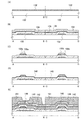
図1(A)に示す薄膜トランジスタは、基板100上に設けられたゲート電極層102と、ゲート電極層102を覆って設けられたゲート絶縁層104と、ゲート電極層102と少なくとも一部が重畳し、離間して設けられた、ソース領域及びドレイン領域を形成する不純物半導体層114a及び不純物半導体層114bと、ゲート絶縁層104上に、チャネル長方向の一部に設けられた微結晶半導体層106と、ゲート絶縁層104上に少なくとも微結晶半導体層106を覆って設けられた半導体層110と、半導体層110と不純物半導体層114a及び不純物半導体層114bの間に設けられた非晶質半導体層112と、を有する。
In the thin film transistor illustrated in FIG. 1A, at least a part of the
より詳細には、図1(A)に示す薄膜トランジスタは、基板100上に設けられたゲート電極層102と、ゲート電極層102を覆って設けられたゲート絶縁層104と、ゲート電極層102と少なくとも一部が重畳し、離間して設けられた、ソース領域及びドレイン領域を形成する不純物半導体層114a及び不純物半導体層114bと、ゲート絶縁層104上に、ゲート電極層102及び不純物半導体層114aと少なくとも一部が重畳し、且つ不純物半導体層114bと重畳せずしてチャネル長方向の一部に設けられた微結晶半導体層106と、ゲート絶縁層104上に少なくとも微結晶半導体層106を覆って設けられた半導体層110と、半導体層110と不純物半導体層114a及び不純物半導体層114bの間に設けられた非晶質半導体層112と、を有する。
More specifically, the thin film transistor illustrated in FIG. 1A includes a
換言すると、図1(A)に示す薄膜トランジスタは、基板100上に設けられたゲート電極層102と、ゲート電極層102を覆って設けられたゲート絶縁層104と、ゲート絶縁層104上に、少なくとも一部が接するように設けられた半導体層110と、半導体層110上に設けられた非晶質半導体層112と、非晶質半導体層112上に離間して設けられた、ソース領域及びドレイン領域を形成する不純物半導体層114a及び不純物半導体層114bと、ゲート絶縁層104と非晶質半導体層112との間に、ゲート電極層102及び不純物半導体層114aと少なくとも一部が重畳し、且つ不純物半導体層114bと重畳せずしてチャネル長方向の一部に設けられた微結晶半導体層106と、を有する。
In other words, the thin film transistor illustrated in FIG. 1A includes at least a
更に換言すると、図1(A)に示す薄膜トランジスタは、基板100上に設けられたゲート電極層102と、ゲート電極層102を覆って設けられたゲート絶縁層104と、ゲート絶縁層104上に、ゲート電極層102と少なくとも一部が重畳して設けられた微結晶半導体層106と、少なくとも微結晶半導体層106を覆って設けられた非晶質半導体層112と、非晶質半導体層112上に、一方が微結晶半導体層106と重畳して設けられ、他方が非晶質半導体層112上に微結晶半導体層106と重畳せずして設けられ、ソース領域及びドレイン領域を形成する不純物半導体層114a及び不純物半導体層114bと、ゲート絶縁層104上に少なくとも微結晶半導体層106を覆って設けられた半導体層110と、を有する。
In other words, the thin film transistor illustrated in FIG. 1A includes a
なお、図1(A)では、好ましい形態として、微結晶半導体層106上にバッファ層108が設けられているが、バッファ層108が設けられていなくてもよい。バッファ層108を設けない場合には、工程が簡略化し、スループットが向上する。
Note that in FIG. 1A, as a preferable mode, the
また、配線層116a及び配線層116bは、不純物半導体層114a及び不純物半導体層114b上に接して設けられている。ただし、これに限定されず、配線層116aの一部が、半導体層110及び非晶質半導体層112の一部に接していてもよい。このときの形態を図1(B)に示す。なお、図1(B)に示す各層は、図1(A)に示す層と同一の符号が付されている限り、同一の層を表す。図1(A)に示す薄膜トランジスタは、例えば、多階調マスクを用いることで形成することができる。そして、多階調マスクを用いない場合に図1(B)に示す薄膜トランジスタを作製することができる。
The
図1(A)に示す薄膜トランジスタの各層について以下に説明する。 Each layer of the thin film transistor illustrated in FIG. 1A will be described below.
基板100としては、ガラス基板、セラミック基板の他、本作製工程の処理温度に耐えうる程度の耐熱性を有するプラスチック基板等を用いることができる。また、基板に透光性を要しない場合には、ステンレス合金等の金属の基板の表面に絶縁層を設けたものを用いてもよい。ガラス基板としては、例えば、バリウムホウケイ酸ガラス、アルミノホウケイ酸ガラス若しくはアルミノケイ酸ガラス等の無アルカリガラス基板を用いればよい。
As the
ゲート電極層102は、モリブデン、チタン、クロム、タンタル、タングステン、アルミニウム、銅、ネオジム、スカンジウム等の金属材料又はこれらを主成分とする合金材料を用いて、単層で又は積層して形成すればよい。厚さは50nm以上500nm以下程度で形成すればよい。ゲート電極層102は、基板100上に、スパッタリング法又は真空蒸着法を用いて上記した材料により導電層を形成し、該導電層上にフォトリソグラフィ法等によりレジストマスクを形成し、該レジストマスクを用いて導電層をエッチングして形成することができる。ここでは、基板100上に導電層を形成し、フォトマスクを用いて形成したレジストマスクによりエッチングする。また、ゲート電極層102を形成する工程によりゲート配線(走査線)も同時に形成することができる。更には、画素部が有する容量線も同時に形成することができる。なお、走査線とは画素を選択する配線をいい、容量線とは画素の保持容量の一方の電極に接続された配線をいう。
The
ゲート絶縁層104は、CVD法又はスパッタリング法等を用いて、窒化シリコン、酸化窒化シリコン又は窒化酸化シリコンを単層で又は積層して形成する。また、ゲート絶縁層104を酸化窒化シリコンにより形成すると、トランジスタの閾値電圧の変動を抑制することができる。また、ゲート絶縁層104を窒化シリコンにより形成すると、薄膜トランジスタのサブスレッショルド係数を小さくすることができる。また、基板100とゲート絶縁層104との密着力を強くすることができる。また、基板100に含まれるナトリウム等の不純物元素が、微結晶半導体層106などへ侵入することを防止できる。更には、ゲート電極層102の酸化を防止することが可能である。
The
また、ゲート絶縁層104は、厚さ50nm以上550nm以下、更には厚さ50nm以上300nm以下で形成することが好ましい。特に、ゲート電極層102をスパッタリング法により形成した場合には、その表面に凹凸を生じることが多い。このような厚さとすることで、凹凸による被覆率の低減を緩和することが可能である。
The
なお、ゲート絶縁層104として、薄膜トランジスタのキャリアが流れる領域において、半導体層110の下に接して窒化シリコン層が設けられ、微結晶半導体層の下にのみ接して酸化窒化シリコン層が設けられていることが好ましい。これは、非晶質半導体を多く含む層に接するゲート絶縁層として酸化窒化シリコンを用いると、トランジスタのしきい値電圧が正電位側にシフトし、更にはサブスレッショルド係数(S値ともいう。)が大きくなるためであり、また、窒化シリコン層上に微結晶半導体層を形成すると、微結晶半導体層のピーリング等が生じやすく、形成が困難なためである。
Note that as the
また、微結晶半導体層106は、その電気伝導度が0.9〜2S・cm−1の範囲であることが好ましい。
The
また、微結晶半導体層106の厚さは5nm以上50nm以下、好ましくは5nm以上30nm以下となるように形成すればよい。
The
微結晶半導体層106には、十分なオン電流を得るために一導電型の不純物元素(ドナーとなる不純物元素)が添加されているとよい。
In order to obtain a sufficient on-state current, an impurity element having one conductivity type (an impurity element serving as a donor) is preferably added to the
微結晶半導体層106の厚さは5nm以上30nm以下、好ましくは10nm以上20nm以下と薄くすることで、薄膜トランジスタのオフ電流を低く保つことができる。また、微結晶半導体層106と、不純物半導体層114a及び不純物半導体層114bの間に非晶質半導体層112が設けられるため、従来の微結晶半導体層を用いた薄膜トランジスタと比較して、オフ電流を低減することができる。
By reducing the thickness of the
バッファ層108は、非晶質半導体により形成すればよい。または、フッ素又は塩素等のハロゲンが添加された非晶質半導体を用いてもよい。バッファ層108の厚さは30nm以上200nm以下、好ましくは50nm以上150nm以下とすればよい。非晶質半導体としては、アモルファスシリコンが挙げられる。また、バッファ層108として、非晶質半導体層、更には水素、窒素又はハロゲンを含む非晶質半導体層を形成することで、微結晶半導体層106が有する結晶粒表面の自然酸化を防止することが可能である。これにより、キャリアが捕獲されうる欠陥の数を低減し、またはキャリアの進行を妨げうる領域を小さくすることができる。そのため、薄膜トランジスタの高速動作が可能となり、オン電流を高めることができる。
The
また、ゲート絶縁層104と非晶質半導体層112との間に、非晶質半導体層112と比較して抵抗率の低い半導体層110を設けることで、キャリアが流れやすくなり、薄膜トランジスタの高速動作が可能である。
Further, by providing the
非晶質半導体層112は、アモルファスシリコンにより形成するとよい。また、非晶質半導体層112に、フッ素又は塩素等が含まれていても良い。また、非晶質半導体層112にリンが含まれる場合には、他の半導体層に含まれるよりも低濃度とするとよい。特に、非晶質半導体層112に微結晶半導体層106よりも低濃度のリンが含まれると、トランジスタのしきい値電圧の変動を抑制することが可能である。また、配線と重畳する非晶質半導体層112の厚さは50nm以上500nm以下とする。
The
非晶質半導体層112は、微結晶半導体層106の側面を覆って形成される。また、非晶質半導体層112は、バッファ層108を覆って形成される。また、微結晶半導体層106の周縁部において、ゲート絶縁層104と非晶質半導体層112が接する。このような構造とすることにより、微結晶半導体層106と、不純物半導体層114a及び不純物半導体層114bとが接しないため、微結晶半導体層106と、不純物半導体層114a及び不純物半導体層114bとの間で生じるリーク電流を低減することができ、薄膜トランジスタのオフ電流を低減することができる。
The
n型の薄膜トランジスタを形成する場合には、一対の不純物半導体層114aと不純物半導体層114bには、不純物元素として例えばリンを添加する。また、p型の薄膜トランジスタを形成する場合には、不純物元素として例えばボロンを添加する。不純物半導体層114a及び不純物半導体層114bは10nm以上100nm以下、好ましくは30nm以上50nm以下の厚さで形成するとよい。
In the case of forming an n-type thin film transistor, phosphorus, for example, is added as an impurity element to the pair of
配線層116a及び配線層116bは、導電性材料により設ければよく、例えば金属材料により形成すればよい。例えば、アルミニウム、アルミニウムに耐熱性向上元素が添加されたもの、若しくはアルミニウムにヒロック防止元素が添加されたもの(以下、これらをアルミニウム合金とよぶ。)を単層で、または積層して形成することが好ましい。ここで、耐熱性向上元素又はヒロック防止元素としては、銅、シリコン、チタン、ネオジム、スカンジウム又はモリブデン等が挙げられる。また、不純物半導体層114a又は不純物半導体層114bと接する側に、チタン、タンタル、モリブデン、タングステン又はこれらの窒化物からなる層を形成し、その上にアルミニウム又はアルミニウム合金を形成した積層構造とすることが好ましい。更には、アルミニウム又はアルミニウム合金上に、チタン、タンタル、モリブデン、タングステン又はこれらの窒化物からなる層を形成した三層構造とすることが好ましい。
The
また、図1(A)に示す薄膜トランジスタでは、非晶質半導体層112が配線層116a及び配線層116bと接さず、バッファ層108上に一対の不純物半導体層114a及び不純物半導体層114bを介して配線層116a及び配線層116bが設けられた構造を示しているが、図1(B)に示すように、非晶質半導体層112の側面が配線層116a及び配線層116bと接する構造としてもよい。なお、多階調マスクを用いて図1(A)に示す薄膜トランジスタを作製することができる。そして、多階調マスクを用いない場合に図1(B)に示す薄膜トランジスタを作製することができる。
In the thin film transistor illustrated in FIG. 1A, the
また、図1(A)に示す薄膜トランジスタは、第1の薄膜トランジスタと第2の薄膜トランジスタが直列に接続されたものである。第1の薄膜トランジスタは、ゲート電極層102、ゲート絶縁層104、微結晶半導体層106、バッファ層108、半導体層110、非晶質半導体層112、不純物半導体層114a及び配線層116aで構成される。第2の薄膜トランジスタは、ゲート電極層102、ゲート絶縁層104、非晶質半導体層112、不純物半導体層114b及び配線層116bで構成される。
The thin film transistor illustrated in FIG. 1A includes a first thin film transistor and a second thin film transistor connected in series. The first thin film transistor includes a
第2の薄膜トランジスタは、非晶質半導体層をチャネル形成領域に用いた薄膜トランジスタである。第1の薄膜トランジスタでは、キャリアが流れる領域は、微結晶半導体層106である。微結晶半導体層106は、電気伝導度が0.9〜2S・cm−1であり、通常の非晶質半導体層と比較して抵抗率が低い。このため、ゲート電極層102に、第2の薄膜トランジスタのしきい値電圧未満の正電圧が印加されている状態でも、微結晶半導体層106に多数のキャリアが誘起された状態となる。第2の薄膜トランジスタのしきい値電圧以上の正電圧がゲート電極層102に印加されると、第2の薄膜トランジスタがオンとなり、微結晶半導体層106に誘起されていた多数のキャリアが、第1の薄膜トランジスタの配線層116a又は第2の薄膜トランジスタの配線層116bへ流れる。
The second thin film transistor is a thin film transistor using an amorphous semiconductor layer for a channel formation region. In the first thin film transistor, a region where carriers flow is the
半導体層110は、第1の領域125及び第2の領域127を有する(図2を参照)。第1の領域125は、非晶質構造及び微小結晶粒128を有する。第2の領域127は、離散的に存在する複数の結晶粒126と、微小結晶粒128と、複数の結晶粒126及び微小結晶粒128の間を充填する非晶質構造とを有する。第1の領域125は、ゲート絶縁層104上に接して、ゲート絶縁層104との界面から厚さt1となる位置まで存在する。第2の領域127は、第1の領域125上に接して、厚さt2となる位置まで存在する。すなわち、結晶粒126の核生成位置は、ゲート絶縁層104の界面からt1の位置となるよう半導体層110の厚さ方向において制御されている。結晶粒126の核生成位置は、半導体層110に含まれる結晶化を抑制する不純物元素の濃度(例えば窒素濃度)により制御されている。
The
結晶粒126の形状は、逆錐形である。ここで、逆錐形とは、多数の平面から構成される面と、多数の平面から構成される面の閉じた曲線または折れ線の周上を一周する点の集合とこの多数の平面から構成される面の外に存在する頂点とを結ぶ線によって作られる面と、で囲まれた立体的形状であって、該頂点が基板側に存在するものをいう。換言すると、後の実施例において説明するように、ゲート絶縁層104と半導体層110との界面から離れた位置から、半導体層110が堆積される方向に向けて、ソース領域及びドレイン領域に達しない領域内において略放射状に成長した形状である。離散的に形成された結晶核のそれぞれが、半導体層の形成と共に結晶の方位に沿って成長することで、結晶粒は、結晶核を起点として結晶の成長方向と垂直な面の面内方向に拡がるように成長する。このように結晶粒を有することで、非晶質半導体よりもオン電流を高くすることができる。また、結晶粒126内には単結晶または双晶を含む。ここで、逆錐形の結晶粒126では、側面は面方位が揃っており、側面の断面形状(図2)は一直線である。そのため、結晶粒126は複数の結晶を含んでいる形態よりも単結晶または双晶を含む形態に近いと考えられる。双晶を含む場合には、複数の結晶を含む場合と比較して、ダングリングボンドが少ないため欠陥数が少なく、オフ電流が小さい。また、複数の結晶を含む場合と比較して、粒界が少なく、オン電流が大きい。なお、結晶粒126には、複数の結晶を含んでいてもよい。
The shape of the
なお、双晶とは、結晶粒界において異なる二つの結晶粒が極めて整合性よく接合していることをいう。即ち、結晶粒界において結晶格子が連続的に連なり、結晶欠陥等に起因するトラップ準位を非常に作りにくい構成となっている。従って、この様な結晶構造を有する領域は実質的に結晶粒界が存在しないと見なすことができる。 Note that the twin crystal means that two different crystal grains are bonded with extremely good consistency at the crystal grain boundary. That is, the crystal lattice is continuously connected at the crystal grain boundary, and the trap level caused by crystal defects or the like is very difficult to create. Therefore, the region having such a crystal structure can be regarded as having substantially no grain boundary.
なお、結晶核の生成を抑制する不純物元素において、シリコン中にあってキャリアトラップを生成しない不純物元素(例えば、窒素)を選択する。一方、シリコンの配位数を減らし、ダングリングボンドを生成する不純物元素(例えば、2配位の酸素)の濃度は低減させる。従って、窒素濃度を低減させずして酸素濃度を低減させるとよい。具体的には、酸素については二次イオン質量分析法によって計測される濃度を5×1018cm−3以下とするとよい。 Note that an impurity element that suppresses generation of crystal nuclei in silicon and does not generate carrier traps (for example, nitrogen) is selected. On the other hand, the number of coordination of silicon is reduced, and the concentration of an impurity element that generates dangling bonds (for example, bicoordinate oxygen) is reduced. Therefore, it is preferable to reduce the oxygen concentration without reducing the nitrogen concentration. Specifically, for oxygen, the concentration measured by secondary ion mass spectrometry may be 5 × 10 18 cm −3 or less.
また、本実施の形態では、ゲート絶縁層104の表面に窒素を存在させて半導体層110を形成する。ここで、窒素濃度は核生成位置を決定するため重要である。窒素が存在するゲート絶縁層104上に半導体層110を形成すると、まず、第1の領域125が形成され、その後、第2の領域127が形成される。ここで、第1の領域125と第2の領域127との界面の位置は窒素濃度により決定される。二次イオン質量分析法によって計測される窒素の濃度が1×1020cm−3以上1×1021cm−3以下、好ましくは2×1020cm−3以上7×1020cm−3以下のときに結晶核を生成し、第2の領域127が形成されることとなる。すなわち、結晶粒126の成長の起点となる結晶核の生成位置において、二次イオン質量分析法によって計測される窒素の濃度は1×1020cm−3以上1×1021cm−3以下、好ましくは2×1020cm−3以上7×1020cm−3以下となる。換言すると、逆錐形を有する結晶粒126の頂点における、二次イオン質量分析法によって計測される窒素の濃度は1×1020cm−3以上1×1021cm−3以下、好ましくは2×1020cm−3以上7×1020cm−3以下である。
In this embodiment, the
また、窒素濃度は、ゲート絶縁層104との界面から離れるにつれて徐々に低下する。窒素濃度は、25nm以上40nm以下の範囲で一桁低下するとよく、好ましくは30nm以上35nm以下で一桁低下することが好ましい。
Further, the nitrogen concentration gradually decreases as the distance from the interface with the
上記説明したように、結晶粒は離散的に存在する。結晶粒を離散的に存在させるためには、結晶の核生成密度を制御することが必要である。窒素濃度を上記の濃度範囲とすることで、結晶粒の核生成密度を制御し、結晶粒を離散的に存在せしめることが可能である。 As explained above, the crystal grains exist discretely. In order to make the crystal grains exist discretely, it is necessary to control the nucleation density of the crystal. By setting the nitrogen concentration within the above-described concentration range, it is possible to control the nucleation density of the crystal grains and allow the crystal grains to exist discretely.
なお、上記したように結晶核の生成を抑制する不純物元素が高濃度(二次イオン質量分析法によって計測される不純物の濃度が概ね1×1020cm−3以上)に存在すると、結晶成長も抑制するため、半導体層110に含ませる窒素は、半導体層の被堆積面にのみ添加し、またはその堆積初期にのみ導入する。
As described above, when the impurity element that suppresses the generation of crystal nuclei is present at a high concentration (impurity concentration measured by secondary ion mass spectrometry is approximately 1 × 10 20 cm −3 or more), crystal growth also occurs. In order to suppress this, nitrogen contained in the
半導体層110の第1の領域125は、非晶質構造及び微小結晶粒128を有する。また、従来の非晶質半導体層と比較して、CPM(Constant Photocurrent Method)やフォトルミネッセンス分光測定で測定されるUrbach端のエネルギーが小さく、欠陥吸収スペクトル量が少ない。これらのことから、従来の非晶質半導体層と比較して、欠陥が少なく、価電子帯のバンド端における準位のテール(裾)の傾きが急峻である秩序性の高い半導体層である。また、半導体層110の第1の領域125を低温フォトルミネッセンス分光によるスペクトルのピーク領域は、1.31 eV以上1.39eV以下である。なお、微結晶半導体層、代表的には微結晶シリコン層を低温フォトルミネッセンス分光によるスペクトルのピーク領域は、0.98eV以上1.02eV以下である。
The
ここで、半導体層110は、NH基を含むことが好ましい。半導体層110にNH基を含ませることで、半導体層110中のダングリングボンドを架橋することができる。
Here, the
本実施の形態の薄膜トランジスタのチャネル長Lは、第1の薄膜トランジスタのチャネル長aと、第2の薄膜トランジスタのチャネル長bの和である。第1の薄膜トランジスタのチャネル長aは、不純物半導体層114aのバックチャネル側端部と、微結晶半導体層106のバックチャネルと重畳する領域における端部との間の距離である。第2の薄膜トランジスタのチャネル長bは、微結晶半導体層106のバックチャネルと重畳する領域におけるゲート絶縁層104と接する端部と、不純物半導体層114bのバックチャネル側端部との距離である。チャネル長aを長くし、チャネル長bを短くすることで、薄膜トランジスタのオン電流が高くなり、移動度も向上する。
The channel length L of the thin film transistor of this embodiment is the sum of the channel length a of the first thin film transistor and the channel length b of the second thin film transistor. The channel length a of the first thin film transistor is a distance between the back channel side end portion of the
なお、チャネル長aに対してチャネル長bを短くする場合には、第2の薄膜トランジスタにおいて短チャネル効果が生じないように、ゲート絶縁層104を薄く形成することが好ましい。
Note that in the case where the channel length b is shorter than the channel length a, it is preferable that the
一方、ゲート電極層102に負の電圧を印加すると、微結晶半導体層106にキャリアが誘起されたとしても、第2の薄膜トランジスタがオフであるため、電流の流れを妨げることができる。第2の薄膜トランジスタは非晶質半導体層により形成され、更にはリークパス等も生じにくいため、オフ電流を小さくすることができる。
On the other hand, when a negative voltage is applied to the
以上説明したように、本発明の一態様である薄膜トランジスタは、オン電流と移動度が大きく、オフ電流が小さいものとなる。更には、本発明の一態様である薄膜トランジスタは、サブスレッショルド係数が小さく、しきい値電圧がシフトしにくいものであり、良好な電気的特性を有する。 As described above, the thin film transistor which is one embodiment of the present invention has high on-state current and mobility and low off-state current. Furthermore, a thin film transistor which is one embodiment of the present invention has a small subthreshold coefficient, a threshold voltage that is difficult to shift, and favorable electrical characteristics.
また、図1に示す薄膜トランジスタは、ソース領域とドレイン領域となる不純物半導体層114aと不純物半導体層114bとの間において、非晶質半導体層112の表面(バックチャネル部)には凹凸形状を有し、ソース領域とドレイン領域との間の距離が十分に長く、リーク電流の経路が長い。バックチャネル部はオフ電流の流れる主な経路の一つである。そのため、ソース領域とドレイン領域との間を長くすることで、オフ電流を小さくすることができる。
1 has an uneven shape on the surface (back channel portion) of the
更には、ゲート電極層102と、不純物半導体層114a及び不純物半導体層114bとの間には、絶縁層の他に非晶質半導体層112が設けられており、ゲート電極層102と、不純物半導体層114aと不純物半導体層114bとの間の距離を長くとることができる。このため、ゲート電極層102と、不純物半導体層114a及び不純物半導体層114bとの間に生じる寄生容量を低減することができる。
Further, an
図1(A)に示す薄膜トランジスタの作製方法について、以下に説明する。 A method for manufacturing the thin film transistor illustrated in FIG. 1A will be described below.
なお、図1(A)に示す薄膜トランジスタは、液晶表示装置等の画素トランジスタとして用いることができるものである。そこで、以下の説明では、画素トランジスタの作製方法について説明する。 Note that the thin film transistor illustrated in FIG. 1A can be used as a pixel transistor in a liquid crystal display device or the like. Therefore, in the following description, a method for manufacturing a pixel transistor will be described.
薄膜トランジスタは、一般にp型よりもn型の方が、電界効果移動度が高く、駆動回路に用いるのに適している。また、同一の基板上に形成する薄膜トランジスタは全て同じ極性とすることが、工程数が少なくなり好ましい。従って、本実施の形態ではn型の薄膜トランジスタの作製工程について説明する。ただし、p型の薄膜トランジスタであっても同様に作製することが可能である。 In general, an n-type thin film transistor has higher field effect mobility than a p-type, and is suitable for use in a driver circuit. In addition, it is preferable that all thin film transistors formed over the same substrate have the same polarity because the number of steps is reduced. Therefore, in this embodiment, a manufacturing process of an n-type thin film transistor is described. However, a p-type thin film transistor can be similarly manufactured.
まず、図1(A)に示す薄膜トランジスタの作製工程について、図3乃至図7を参照して説明する。なお、図3および図4中のA−B、C−Dはそれぞれ図5のA−Bにおける断面図および図5のC−Dにおける断面図を示す。 First, a manufacturing process of the thin film transistor illustrated in FIG. 1A will be described with reference to FIGS. In FIGS. 3 and 4, AB and CD indicate a cross-sectional view taken along AB in FIG. 5 and a cross-sectional view taken along CD in FIG. 5, respectively.
まず、基板100上に導電層132を形成する(図3(A)を参照)。導電層132は、後の工程によりゲート電極層102となるものである。従って、導電層132は、ゲート電極層102を形成する材料及び方法を用いて形成することができる。
First, the
次に、導電層132上にレジストを塗布し、第1のフォトマスクを用いたフォトリソグラフィ工程によってレジストマスクを形成する。このレジストマスクを用いて導電層132を所望の形状にエッチングし、ゲート電極層102を形成する。その後、レジストマスクを除去する。
Next, a resist is applied over the
次に、基板100上に、ゲート電極層102を覆ってゲート絶縁層104を形成する。ゲート絶縁層104は、上記した材料及び方法により形成することができる。
Next, a
次に、ゲート絶縁層104上に微結晶半導体層136を形成する(図3(B)を参照)。
Next, a
微結晶半導体層136は、プラズマCVD装置の処理室内において、シリコンを含む堆積性気体と、水素とを混合し、グロー放電プラズマにより形成することができる。シリコンを含む堆積性気体の流量に対して、水素の流量を10〜2000倍、好ましくは50〜200倍として希釈することで微結晶半導体層136を形成することができる。基板は100℃〜300℃、好ましくは120℃〜300℃まで加熱して処理を行う。上記の原料ガスと共に、リン、ヒ素、アンチモン等を含む気体を混合すると、ドナーとなる不純物元素を添加することができる。ここでは、シランと、水素と、希ガスとの混合ガス(または水素及び希ガスのいずれかのみでもよい。)にフォスフィンを混合して、グロー放電プラズマにより、リンを含む微結晶半導体層136を形成する。
The
ここで、グロー放電プラズマの生成は、1MHzから20MHz(代表的には13.56MHz)の高周波電力、または20MHzより大きく120MHz程度まで(代表的には27.12MHz、60MHz)のVHF帯の高周波電力を印加することで行うことができる。 Here, the glow discharge plasma is generated by high frequency power of 1 MHz to 20 MHz (typically 13.56 MHz), or high frequency power of VHF band from 20 MHz to about 120 MHz (typically 27.12 MHz, 60 MHz). This can be done by applying.
また、シリコンを含む堆積性気体として代表的には、SiH4又はSi2H6等が挙げられる。 A typical example of the deposition gas containing silicon is SiH 4 or Si 2 H 6 .
なお、ドナーとなる不純物元素は、微結晶半導体層136に直接添加せず、ゲート絶縁層104にドナーとなる不純物元素を含ませることで行ってもよい。ゲート絶縁層104にドナーとなる不純物元素を含ませるためには、ゲート絶縁層104の原料ガス中にフォスフィンを含ませればよい。例えば、シラン、アンモニア及びフォスフィンを含む混合ガスを用いたプラズマCVD法によりリンを含む窒化シリコン層を形成することができる。または、シラン、一酸化二窒素、アンモニア及びフォスフィンを含む混合ガスを用いたプラズマCVD法により、リンを含む酸化窒化シリコン層を形成することができる。
Note that the impurity element serving as a donor may be added by adding the impurity element serving as a donor to the
または、微結晶半導体層136を形成する前に、処理室内にドナーとなる不純物元素を含む気体を流し、ゲート絶縁層104の表面及び処理室の内壁にドナーとなる不純物元素を吸着させておいてもよい。その後、微結晶半導体層136の形成を行うことで、ドナーとなる不純物元素を取り込みつつ半導体層を形成することができる。
Alternatively, before the
または、ゲート絶縁層104の原料ガス中にフォスフィンを含ませ、更にゲート絶縁層104をフォスフィンに曝してもよい。
Alternatively, phosphine may be included in the source gas of the
なお、ゲート絶縁層104の表面は、形成後にプラズマ処理するとよい。ここで、代表的には、水素プラズマ、アンモニアプラズマ、水プラズマ、ヘリウムプラズマ、アルゴンプラズマ又はネオンプラズマ等のプラズマのいずれか一又は複数によるプラズマにゲート絶縁層104の表面を曝すことにより行うことができる。この結果、ゲート絶縁層104の表面に生じる欠陥の密度を低減することができる。ゲート絶縁層104の表面のダングリングボンドを終端することができるからである。
Note that the surface of the
次に、微結晶半導体層136上に、後の工程でバッファ層108となるバッファ層138を形成する。バッファ層138の形成は、シリコンを含む堆積性気体を用いたプラズマCVD法によればよい。または、シリコンを含む堆積性気体を、ヘリウム、アルゴン、クリプトン及びネオンから選ばれた一種又は複数種の希ガス元素で希釈することでバッファ層138を形成することができる。シリコンを含む堆積性気体の流量に対して、水素の流量を1〜2000倍、好ましくは1〜10倍、更に好ましくは1〜5倍に希釈することでバッファ層138を形成することができる。また、シランガスの流量の1〜10倍、好ましくは1〜5倍の流量で水素を導入することで、水素を含むバッファ層138を形成することができる。バッファ層138の形成に用いるガス中には、フッ素又は塩素等のハロゲンを添加してもよい。なお、バッファ層138の形成に際して、形成ガス中におけるシランガスの流量は、少なくとも微結晶半導体層136の形成時の流量よりも高いものとすることが好ましい。
Next, a
また、バッファ層138は、シリコンのターゲットを用いて、水素又は希ガス雰囲気中でスパッタリングを行って形成することもできる。
Alternatively, the
また、バッファ層138は、プラズマCVD法により300℃〜400℃の温度で形成することが好ましい。この処理により水素が微結晶半導体層136に含まれ、水素化した場合と同等の効果が得られる。すなわち、微結晶半導体層136上に上記条件でバッファ層138を形成することにより、微結晶半導体層136に水素を拡散させて、ダングリングボンドを終端させることができる。
The
また、バッファ層138を設けることで、微結晶半導体層136に含まれる結晶粒表面の自然酸化を防止することが可能である。バッファ層138には水素、窒素又はハロゲンを含ませてもよい。特に、バッファ層138と微結晶半導体層136の結晶粒が接する領域では、局所的な応力により亀裂が入りやすい。この亀裂が酸素に触れると結晶粒は酸化され、薄い酸化シリコン層が形成される。しかしながら、バッファ層138を設けることで、微結晶半導体層136に含まれる結晶粒の酸化を防ぐことができる。また、バッファ層138を厚く形成すると、薄膜トランジスタの耐圧が高くなる。そのため、高電圧による薄膜トランジスタの破壊及び劣化を防止することができる。
In addition, by providing the
次に、バッファ層138上にレジストを塗布した後、フォトリソグラフィ法によりレジストマスクを形成する。このレジストマスクを用いて、バッファ層138を所望の形状にエッチングすることで、バッファ層108を形成する。その後、レジストマスクを除去する。
Next, after applying a resist on the
レジストマスクを除去した後に、バッファ層108をマスクとして用いて微結晶半導体層136をエッチングし、微結晶半導体層106を形成する(図3(C)を参照)。この工程により、バッファ層108と重畳しない領域のゲート絶縁層104の一部もエッチングされうる。ここで、ゲート絶縁層104が窒化シリコン層上に酸化窒化シリコン層が積層されて設けられている場合には、バッファ層108と重畳しない領域の酸化窒化シリコン層が除去されることが好ましい。なお、バッファ層108をマスクとして用いることなく、バッファ層108を形成したレジストマスクを用いて微結晶半導体層136をエッチングしてもよい。
After the resist mask is removed, the
ここで、半導体層140の形成前にフッ酸により表面を清浄にするとよい。
Here, the surface may be cleaned with hydrofluoric acid before the
次に、半導体層140を形成する。半導体層140の形成条件は、微結晶半導体層106の形成時の条件と同様のものとすればよいが、結晶化を抑制する不純物元素を含ませる点が異なる。
Next, the
ここで、結晶核の生成を抑制する不純物元素は、シリコン中にあってキャリアトラップを生成しないもの(例えば、窒素)を選択する。一方、シリコンの配位数を減らし、ダングリングボンドを生成する不純物元素(例えば酸素)の濃度は低減させる。従って、窒素濃度を低減させずして酸素濃度を低減させるとよい。具体的には、酸素については二次イオン質量分析法によって計測される濃度を5×1018cm−3以下とするとよい。 Here, an impurity element that suppresses generation of crystal nuclei is selected from those that are in silicon and do not generate carrier traps (for example, nitrogen). On the other hand, the coordination number of silicon is reduced, and the concentration of an impurity element (for example, oxygen) that generates dangling bonds is reduced. Therefore, it is preferable to reduce the oxygen concentration without reducing the nitrogen concentration. Specifically, for oxygen, the concentration measured by secondary ion mass spectrometry may be 5 × 10 18 cm −3 or less.
また、半導体層140は、窒素が存在するゲート絶縁層104、微結晶半導体層106及びバッファ層108を覆って形成し、二次イオン質量分析法によって計測される窒素の濃度が1×1020cm−3以上1×1021cm−3以下、特に、2×1020cm−3以上7×1020cm−3以下のときに結晶核を生成する。すなわち、結晶粒の成長の起点となる結晶核の生成位置において、二次イオン質量分析法によって計測される窒素濃度は1×1020cm−3以上1×1021cm−3以下、好ましくは2×1020cm−3以上7×1020cm−3以下となる。なお、窒素濃度を上記範囲とすることで、結晶核の生成を抑制し、結晶核の生成を離散的に存在する程度の状態とすることができるため、複数の結晶領域が接して形成されることを抑制し、オン電流を向上させることができる。
The
なお、窒素濃度を上記範囲として結晶核を生成させ、半導体層140が徐々に形成される方向において窒素の濃度を低減させつつ半導体材料を堆積していくことで、該結晶核を起点として略放射状に成長させ、逆錐形状の結晶領域を形成してもよい。このような結晶領域を形成すると、双晶を含む単結晶に近い結晶領域を形成することができる。この場合にも、逆錐形状の結晶領域は離散的に存在させる。
Note that crystal nuclei are generated with the nitrogen concentration in the above range, and a semiconductor material is deposited while reducing the concentration of nitrogen in the direction in which the
また、窒素濃度は、ゲート絶縁層104との界面から離れるにつれて徐々に低下する。窒素濃度は、25nm以上40nm以下の範囲で一桁低下するとよく、好ましくは30nm以上35nm以下で一桁低下することが好ましい。
Further, the nitrogen concentration gradually decreases as the distance from the interface with the
なお、結晶核の生成を抑制する不純物元素が半導体層140の全体に高濃度(二次イオン質量分析法によって計測される不純物元素の濃度が概ね1×1020cm−3以上)に存在することは好ましくない。そこで、このような不純物元素は、半導体層140の被形成面にのみ添加し、またはその形成初期にのみ導入することが好ましい。
Note that the impurity element that suppresses the generation of crystal nuclei is present in the
次に、半導体層140の形成方法について説明する。半導体層140は、2nm以上60nm以下、好ましくは10nm以上30nm以下の厚さで形成するとよい。
Next, a method for forming the
また、上記のような半導体層140を形成するに際して、酸素濃度を低く抑えて、窒素濃度を酸素濃度よりも高くする手段としては、以下に示すものが挙げられる。
In addition, when forming the
上記のような半導体層140を形成するに際して、酸素濃度を低く抑え、窒素濃度を酸素濃度よりも高くする手段の一は、半導体層140の被形成面に、高濃度に窒素を含ませることである。従って、ゲート絶縁層104を窒化シリコンにより形成すればよい。
In forming the
または、上記のような半導体層140を形成するに際して、酸素濃度を低く抑え、窒素濃度を酸素濃度よりも高くする手段の一は、半導体層140の形成前に、被形成面に多量の窒素を存在させることである。被形成面に多量の窒素を存在させるためには、ゲート絶縁層104の形成後、半導体層140の形成前に、ゲート絶縁層104の表面を、窒素を含むガスによって生成されるプラズマにより処理すればよい。ここで、窒素を含むガスとしては、例えばアンモニアが挙げられる。
Alternatively, when forming the
または、上記のような半導体層140を形成するに際して、酸素濃度を低く抑え、窒素濃度を酸素濃度よりも高くする手段の一は、半導体層140の形成に用いる処理室(チャンバー)の内壁を、高濃度に窒素を含む膜により覆うことである。高濃度に窒素を含む膜として、例えば窒化シリコン膜が挙げられる。なお、処理室(チャンバー)の内壁を覆う高濃度に窒素を含む膜は、ゲート絶縁層104と同時に形成してもよく、同時に形成すると工程の簡略化ができるため好ましい。また、この場合には、ゲート絶縁層104の形成に用いる処理室(チャンバー)と微結晶半導体層106の形成に用いる処理室(チャンバー)が同一のものとなるため、装置が小型化される。
Alternatively, in forming the
または、上記のような半導体層140を形成するに際して、酸素濃度を低く抑え、窒素濃度を酸素濃度よりも高くする手段の一は、半導体層140の形成に用いるガスに含まれる酸素の濃度を低く抑え、窒素濃度を高くすることである。このとき、窒素は半導体層140の形成初期に用いるガスにのみ導入し、または導入する窒素の量を減少させていけばよい。
Alternatively, in the formation of the
なお、ここでは上記手段の一を用いてもよいし、これらを組み合わせて用いてもよい。ここでは、ゲート絶縁層104は窒化シリコン層上に酸化窒化シリコン層を積層した構造とし、ゲート絶縁層104をアンモニアに曝すことで、半導体層140の被形成面に窒素を供給する。
Here, one of the above means may be used, or a combination thereof may be used. Here, the
ここで、ゲート絶縁層104、半導体層140、バッファ層138、非晶質半導体層142並びに不純物半導体層144の形成方法の一例について詳細に説明する。なお、以下で説明する形成方法は一例であり、これに限定されない。これらの層はCVD法等を用いて形成する。また、ゲート絶縁層104は、窒化シリコン層上に酸化窒化シリコン層を設けた積層構造とする。このような構造とすることで、窒化シリコン層により基板中に含まれる電気的特性に影響を及ぼす元素(基板がガラスである場合にはナトリウム等の元素)が、半導体層140等に侵入することを防止することができる。図7は、これらを形成するに際して用いるCVD装置の模式図を示す。
Here, an example of a method for forming the
図7に断面図を示すプラズマCVD装置200は、ガス導入手段189及び排気手段190に接続されている。
The
図7に示すプラズマCVD装置200は、処理室180と、ステージ181と、ガス導入部182と、シャワープレート183と、排気口184と、上部電極185と、下部電極186と、交流電源187と、温度制御部188と、を具備する。
A
処理室180は剛性のある素材で形成され、内部を真空排気できるように構成されている。処理室180には、上部電極185と下部電極186が備えられている。なお、図7では、容量結合型(平行平板型)の構成を示しているが、異なる二以上の高周波電力を印加して処理室180の内部にプラズマを生成できるものであれば、誘導結合型など他の構成を適用してもよい。
The
図7に示すプラズマCVD装置により処理を行う際には、所定のガスをガス導入部182から導入する。導入されたガスは、シャワープレート183を通って、処理室180に導入される。上部電極185と下部電極186に接続された交流電源187により、高周波電力が印加されて処理室180内のガスが励起され、プラズマが生成される。また、真空ポンプに接続された排気口184によって、処理室180内のガスが排気されている。また、温度制御部188によって、被処理物を加熱しながらプラズマ処理することができる。
When processing is performed by the plasma CVD apparatus shown in FIG. 7, a predetermined gas is introduced from the
ガス導入手段189は、反応ガスが充填されるシリンダ191、圧力調整弁192、ストップバルブ193、マスフローコントローラ194などで構成されている。処理室180内において、上部電極185と基板100との間には複数の細孔を有し板状に加工されたシャワープレートが配されている。上部電極185まで導入された反応ガスは、内部の中空構造を経て、この細孔から処理室180内に導入される。
The gas introduction means 189 includes a
処理室180に接続される排気手段190は、真空排気と、反応ガスを流す場合において処理室180内を所定の圧力に保持するように制御する機能が含まれている。排気手段190には、バタフライバルブ195、コンダクタンスバルブ196、ターボ分子ポンプ197、ドライポンプ198などが含まれる。バタフライバルブ195とコンダクタンスバルブ196を並列に配置する場合には、バタフライバルブ195を閉じてコンダクタンスバルブ196を動作させることで、反応ガスの排気速度を制御して処理室180の圧力を所定の範囲に保つことができる。また、コンダクタンスの大きいバタフライバルブ195を開くことで高真空排気が可能となる。
The
なお、処理室180を10−5Paよりも低い圧力まで排気する場合には、クライオポンプ199を併用することが好ましい。その他、到達真空度として超高真空まで排気する場合には、処理室180の内壁を鏡面加工し、内壁からのガス放出を低減するためにベーキング用のヒータを設けてこれを用いても良い。
In addition, when exhausting the
なお、図7に示すように、処理室180の全体を覆って膜が形成(被着)されるようにプレコート処理を行うと、処理室(チャンバー)内壁に付着した不純物元素、または処理室(チャンバー)内壁を構成する不純物元素が素子に混入することを防止することができる。本実施の形態では、プレコート処理はシリコンを主成分とする膜を形成すればよく、例えば、非晶質シリコン膜等を形成すればよい。ただし、この膜には酸素が含まれないことが好ましい。
As shown in FIG. 7, when pre-coating treatment is performed so that a film is formed (deposited) so as to cover the
ここで、ゲート絶縁層104の形成から不純物半導体層154の形成までについて、以下に説明する。なお、ゲート絶縁層104は、窒化シリコン層上に酸化窒化シリコン層を積層して形成する。
Here, a process from formation of the
まず、ゲート電極層102が形成された基板をCVD装置の処理室180内にて加熱し、窒化シリコン層を形成するために、窒化シリコン層の形成に用いる材料ガスを処理室180内に導入する。ここでは、一例として、SiH4の流量を40sccm、H2の流量を500sccm、N2の流量を550sccm、NH3の流量を140sccmとして材料ガスを導入して安定させ、処理室180内の圧力を100Pa、温度を280℃とし、370Wのプラズマ放電を行うことで、約110nmの窒化シリコン層を形成する。その後、SiH4の導入のみを停止して数秒後にプラズマの放電を停止させる。処理室内にSiH4が存在する状態でプラズマの放電を停止させると、シリコンを主成分とする粒状物又は粉状物が形成され、歩留まりを低下させる原因となるためである。なお、N2ガス及びNH3ガスはいずれか一方を用いればよく、これらを混合して用いる場合には流量を適宜調整するとよい。また、H2ガスの導入及び流量は適宜調整し、不要な場合には導入しなくてもよい。
First, the substrate over which the
次に、窒化シリコン層の形成に用いた材料ガスを排気し、酸化窒化シリコン層の形成に用いる材料ガスを処理室180内に導入する。ここでは、一例として、SiH4の流量を30sccm、N2Oの流量を1200sccmとし、材料ガスを導入して安定させ、処理室180内の圧力を40Pa、温度を280℃として50Wのプラズマ放電を行うことで、約110nmの酸化窒化シリコン層を形成する。その後、窒化シリコン層と同様に、SiH4の導入のみを停止し、その数秒後にプラズマの放電を停止させる。
Next, the material gas used for forming the silicon nitride layer is exhausted, and the material gas used for forming the silicon oxynitride layer is introduced into the
微結晶半導体層の形成は、一例として、SiH4の流量を10sccm、0.5vol%フォスフィン(PH3の流量をH2により0.5%まで希釈)の流量を30sccm、H2の流量を1500sccmとし、材料ガスを導入して安定させ、処理室内の圧力を280Pa、温度を280℃として300Wのプラズマ放電を行うことにより可能である。 For example, the formation of the microcrystalline semiconductor layer is as follows. The flow rate of SiH 4 is 10 sccm, the flow rate of 0.5 vol% phosphine (the flow rate of PH 3 is diluted to 0.5% with H 2 ) is 30 sccm, and the flow rate of H 2 is 1500 sccm. This is possible by introducing and stabilizing the material gas, and performing plasma discharge at 300 W at a pressure of 280 Pa and a temperature of 280 ° C. in the processing chamber.
次に、微結晶半導体層の形成に用いた材料ガスを排気し、非晶質半導体層の形成に用いる材料ガスを処理室180に導入する。ここでは、一例として、SiH4の流量を280sccm、H2の流量を300sccmとし、材料ガスを導入して安定させ、処理室内の圧力を170Pa、温度を280℃として60Wのプラズマ放電を行うことで、約75nmの非晶質半導体層を形成する。その後、窒化シリコン層等と同様に、SiH4の導入のみを停止し、その数秒後にプラズマの放電を停止させる。
Next, the material gas used for forming the microcrystalline semiconductor layer is exhausted, and the material gas used for forming the amorphous semiconductor layer is introduced into the
非晶質半導体によりバッファ層138を形成した後、基板100を処理室180から搬出し、フォトリソグラフィ法によりレジストマスクを形成する。このレジストマスクを用いてエッチングを行うことで、微結晶半導体層106及びバッファ層108を形成する。このエッチング工程により、ゲート絶縁層104は、微結晶半導体層106と重畳する領域にのみ酸化窒化シリコン層が残存し、微結晶半導体層106と重畳しない領域においては酸化窒化シリコン層が除去される。その後、当該レジストマスクを除去する。
After the
基板100を処理室180から搬出した後、処理室180に、例えばNF3ガスを導入し、処理室180内をクリーニングする。その後、処理室180の内壁を非晶質シリコン膜により覆う。これは、後に説明するバッファ層138等の形成と同様に行うが、水素は処理室180内に導入してもよいし、導入しなくてもよい。この処理により、処理室180の内壁が非晶質シリコン膜により覆われる。または、窒化シリコン膜によりプレコート処理を行ってもよい。この場合の処理は、ゲート絶縁層104を形成する処理と同様である。その後、基板100を処理室180内に搬入し、アンモニアガスを処理室180内に導入する。
After the
次に、半導体層140の被形成面に窒素を供給する。ここでは、ゲート絶縁層104、微結晶半導体層106及びバッファ層108をアンモニアガスに曝すことで窒素を供給する。また、アンモニアガスには水素を含ませてもよい。ここでは、一例として、処理室180内の圧力は概ね20Pa〜30Pa、温度は280℃とし、処理時間は60秒間とするとよい。なお、本工程の処理では基板100をアンモニアガスに曝すのみであるが、プラズマ処理を行ってもよい。その後、これらのガスを排気し、半導体層140の形成に用いる材料ガスを処理室180内に導入する。
Next, nitrogen is supplied to the formation surface of the
なお、半導体層140の被形成面に窒素を供給する前に、フッ酸により被形成面を清浄にしてもよい。
Note that the surface to be formed may be cleaned with hydrofluoric acid before nitrogen is supplied to the surface to be formed of the
次に、窒素が供給された半導体層140の被形成面の全面に半導体層140を形成する。半導体層140は、後の工程でパターン形成されて半導体層110となるものである。まず、半導体層140の形成に用いる材料ガスを処理室内に導入する。ここでは、一例として、SiH4の流量を10sccm、H2の流量を1500sccmとして材料ガスを導入して安定させ、処理室内の圧力を280Pa、温度を280℃とし、300Wのプラズマ放電を行うことで、約50nmの半導体層140を形成することができる。その後、上記した窒化シリコン層等の形成と同様に、SiH4の導入のみを停止し、その数秒後にプラズマの放電を停止させる。その後、これらのガスを排気し、非晶質半導体層142の形成に用いるガスを導入する。
Next, the
上記の例において、半導体層140の形成に用いられる材料ガスでは、SiH4の流量に対するH2の流量を150倍としている。そのため、シリコンは徐々に堆積される。
In the above example, in the material gas used for forming the
本実施の形態における半導体層140の被形成面には窒素が供給されている。上記したように、窒素はシリコンの結晶核の生成を抑制する。そのため、少なくとも形成の初期段階ではシリコンの結晶核が生成されない。上記したようにゲート絶縁層104等の表面に窒素を供給し、該表面上に半導体層140を形成することで、窒素を含む半導体層140を形成する。半導体層140の形成は窒素の濃度を低下させつつ進み、窒素の濃度が一定の値以下となると、形成された厚さと窒素濃度の関係によっては結晶核が生成される。この場合、その後にその結晶核が成長して結晶粒が生成されるが、結晶核が生成される場合であっても、離散的に存在するに留まる。
Nitrogen is supplied to the formation surface of the
次に、半導体層140上の全面に非晶質半導体層142を形成する。非晶質半導体層142は、後の工程でパターン形成されて非晶質半導体層112となるものである。非晶質半導体層142の形成は、一例として、SiH4の流量を280sccm、H2の流量を300sccmとして材料ガスを導入して安定させ、処理室内の圧力を170Pa、温度を280℃とし、60Wのプラズマ放電を行うことで、約150nmの非晶質半導体層142を形成することができる。その後、上記した窒化シリコン層等の形成と同様に、SiH4の導入のみを停止し、その数秒後にプラズマの放電を停止させる。その後、これらのガスを排気し、不純物半導体層144の形成に用いるガスを導入する。
Next, an
次に、非晶質半導体層142上の全面に不純物半導体層144を形成する。不純物半導体層144は、後の工程でパターン形成されてソース領域及びドレイン領域となるものである。まず、不純物半導体層144の形成に用いる材料ガスを処理室180内に導入する。ここでは、一例として、SiH4の流量を100sccm、PH3をH2により0.5vol%まで希釈した混合ガスの流量を170sccmとして材料ガスを導入して安定させる。処理室180内の圧力を280Pa、温度を280℃とし、60Wのプラズマ放電を行うことで、約50nmの不純物半導体層144を形成することができる。その後、上記した窒化シリコン等の形成と同様に、SiH4の導入のみを停止し、その数秒後にプラズマの放電を停止させる。その後、これらのガスを排気する。
Next, an
以上説明したように、不純物半導体層144までを形成することができる。
As described above, up to the
なお、非晶質半導体層142を形成する際には、プラズマCVD装置の処理室内壁に窒化酸化シリコン層、窒化シリコン層、酸化シリコン層及び酸化窒化シリコン層をプリコートした後に、シリコンを含む堆積性気体の流量に対して、水素の流量を10〜2000倍、好ましくは50〜200倍に希釈して半導体層を形成すると、処理室内壁に存在する酸素及び窒素等を取り込みつつ半導体材料が堆積するため、結晶化を抑制しつつ、緻密な非晶質半導体層を形成することができる。ただし、非晶質半導体層142中の一部に結晶粒が含まれていてもよい。
Note that when the
なお、不純物半導体層144は、シリコンを含む堆積性気体と、フォスフィンの混合ガスを用いたプラズマCVD法により形成することができる。なお、pチャネル型の薄膜トランジスタを形成する場合には、不純物半導体層144は、シリコンを含む堆積性気体と、ジボランの混合ガスを用いたプラズマCVD法により形成することができる。
Note that the
なお、微結晶半導体層136、バッファ層138、非晶質半導体層142及び不純物半導体層144の形成工程においてグロー放電プラズマの生成は、1MHzから20MHz(代表的には13.56MHz)の高周波電力、または20MHzより大きく120MHz程度(代表的には27.12MHz、60MHz)までのVHF帯の高周波電力を印加することで行うことができる。
Note that in the step of forming the
次に、不純物半導体層144上に導電層146を形成する。導電層146は、後の工程により配線層116a、配線層116b及び配線層116cとなるものである。従って、配線層116を形成する材料及び方法により形成することができる。なお、導電層146は、複数の層を積層して形成してもよい。
Next, a
次に、導電層146上に第1のレジストマスク161を形成する(図3(E)を参照)。第1のレジストマスク161は厚さの異なる二の領域を有する。このようなレジストマスクは、多階調マスクを用いて形成することができる。多階調マスクを用いることで、使用するフォトマスクの枚数が低減され、作製工程数が減少するため好ましい。
Next, a first resist
第1のレジストマスク161は、一般的な多階調マスクを用いることで形成することができる。ここで、多階調マスクについて図6を参照して以下に説明する。
The first resist
多階調マスクとは、多段階の光量で露光を行うことが可能なマスクであり、代表的には、露光領域、半露光領域及び未露光領域の3段階の光量で露光を行う。多階調マスクを用いることで、一度の露光及び現像工程によって、複数(代表的には二種類)の厚さを有するレジストマスクを形成することができる。そのため、多階調マスクを用いることで、フォトマスクの枚数を削減することができる。 A multi-tone mask is a mask that can be exposed with multiple levels of light, and typically, exposure is performed with three levels of light: an exposed area, a half-exposed area, and an unexposed area. By using a multi-tone mask, a resist mask having a plurality of thicknesses (typically two types) can be formed by one exposure and development process. Therefore, the number of photomasks can be reduced by using a multi-tone mask.
図6(A−1)及び図6(B−1)は、代表的な多階調マスクの断面図を示す。図6(A−1)にはグレートーンマスク170を示し、図6(B−1)にはハーフトーンマスク175を示す。
6A-1 and 6B-1 are cross-sectional views of typical multi-tone masks. FIG. 6A-1 shows a
図6(A−1)に示すグレートーンマスク170は、透光性を有する基板171上に遮光材料により形成された遮光部172、及び遮光部172に対してパターンを設けた回折格子部173で構成されている。
A gray-
回折格子部173は、露光に用いる光の解像度限界以下の間隔で設けられたスリット、ドット又はメッシュ等を有することで、光の透過量を制御する。なお、回折格子部173に設けられるスリット、ドット又はメッシュは周期的なものであってもよいし、非周期的なものであってもよい。
The
透光性を有する基板171としては、石英等を用いることができる。遮光部172及び回折格子部173を構成する遮光膜は、金属を用いて形成すればよく、好ましくはクロム又は酸化クロム等により形成される。
As the
グレートーンマスク170に露光するための光を照射した場合、図6(A−2)に示すように、遮光部172に重畳する領域における透光率は0%となり、遮光部172又は回折格子部173が設けられていない領域における透光率は100%となる。また、回折格子部173における透光率は、概ね10〜70%の範囲であり、回折格子のスリット、ドット又はメッシュの間隔等により調整することができる。
When the
図6(B−1)に示すハーフトーンマスク175は、透光性を有する基板176上に半透光性の材料により形成された半透光部177、及び遮光材料により形成された遮光部178で構成されている。
A
半透光部177は、MoSiN、MoSi、MoSiO、MoSiON、CrSi等を用いて形成することができる。遮光部178は、グレートーンマスク170の遮光部172と同様の金属を用いて形成すればよく、好ましくはクロム又は酸化クロム等により形成される。
The
ハーフトーンマスク175に露光するための光を照射した場合、図6(B−2)に示すように、遮光部178に重畳する領域における透光率は0%となり、遮光部178又は半透光部177が設けられていない領域における透光率は100%となる。また、半透光部177における透光率は、概ね10〜70%の範囲であり、形成する材料の種類又は厚さ等により、調整することができる。
When light for exposure is applied to the
多階調マスクを用いて露光して現像を行うことで、厚さの異なる領域を有するレジストマスクを形成することができる。 By performing exposure and development using a multi-tone mask, a resist mask having regions with different thicknesses can be formed.
多階調マスクにより形成した第1のレジストマスク161により、半導体層140、非晶質半導体層142、不純物半導体層144及び導電層146をエッチングする。この結果、半導体層110、非晶質半導体層152、不純物半導体層154及び導電層156を形成することができる。
The
次に、第1のレジストマスク161を後退させて第2のレジストマスク162とする。第1のレジストマスク161を後退させる手段としては、例えば酸素プラズマによるアッシングが挙げられる。第1のレジストマスク161を後退させることにより、レジストマスクの面積が縮小し、厚さが薄くなる。このとき、厚さの薄い領域のレジストマスク(ゲート電極層102の一部と重畳する領域であって、図3(E)中の第1のレジストマスク161の凹部)は除去され、第2のレジストマスク162が形成される(図4(F)を参照)。
Next, the first resist
次に、第2のレジストマスク162を用いて、非晶質半導体層152、不純物半導体層154及び導電層156をエッチングする(図4(G)を参照)。まず、第2のレジストマスク162を用いて導電層156をエッチングし、配線層116a及び配線層116bを形成する。第2のレジストマスク162を用いて導電層156をウエットエッチングすると、端部が選択的にエッチングされる。その結果、第2のレジストマスク162より面積の小さい配線層116a、配線層116b及び配線層116cを形成することができる。ただし、これに限定されず、ドライエッチングを用いてもよい。
Next, the
次に、第2のレジストマスク162を用いて不純物半導体層154をエッチングして、不純物半導体層114a、不純物半導体層114b及び不純物半導体層114cを形成する。なお、このエッチング工程において、非晶質半導体層152の一部もエッチングされて、非晶質半導体層112が形成される。
Next, the
ここで、ゲート電極層102と配線層116cの交差部(図4(G)右図)に着目する。ここまでの工程で、ゲート電極層102と配線層116cの間には、ゲート絶縁層104の他に、微結晶半導体層106b、バッファ層108b、及び非晶質半導体層112、不純物半導体層114cが形成されている。このような構造とすることで、ゲート電極層102と配線層116cの間隔を広くとることができる。このため、ゲート電極層102と配線層116cが交差する領域での寄生容量を低減することができる。
Here, attention is focused on the intersection (the right diagram in FIG. 4G) of the
なお、ここでは、配線層116aの端部と不純物半導体層114aの端部は一致せず、配線層116bの端部と不純物半導体層114bの端部は一致せず、配線層116a及び配線層116bの端部の外側に、不純物半導体層114a及び不純物半導体層114bの端部が形成される。その後、第2のレジストマスク162を除去する。第2のレジストマスク162を除去する手段として、好ましくは次の二つのいずれかを用いる。
Note that here, the end portion of the
第2のレジストマスク162を除去する手段の一としては、アッシングにより後退させた後に剥離する手段が挙げられる。この場合、第2のレジストマスク162を除去した後に、バックチャネル部におけるエッチング残渣等の除去を目的としてドライエッチングを行うことが好ましい。ここで、ドライエッチングは、バックチャネル部の非晶質半導体層112にダメージを与えぬよう、無バイアスで行うことが好ましい。エッチングガスとしては、例えば塩素ガスを用いることができる。このエッチング工程を経ることで、薄膜トランジスタのオフ電流を低減することができる。
As one of means for removing the second resist
または、第2のレジストマスク162を除去する手段の一としては、H2Oプラズマ処理が挙げられる。ここで、H2Oプラズマ処理は、代表的には、気化した水を含む雰囲気中でプラズマ放電してラジカルを生成させ、このラジカルを被照射面に照射することで行うことができる。非晶質半導体層112のバックチャネル部が露出した状態でH2Oプラズマ処理を行うことで、薄膜トランジスタの電気的特性を良好にすることができる。
Alternatively, an example of means for removing the second resist
なお、第2のレジストマスク162の除去をH2Oプラズマ処理により行う場合にも、バックチャネル部におけるエッチング残渣等の除去を目的として行う上記のドライエッチング工程を行ってもよい。この場合、H2Oプラズマ処理の後にドライエッチングを行うことになる。
Note that when the second resist
なお、第2のレジストマスク162の除去をアッシング後に剥離する手段による場合であっても、バックチャネル部におけるエッチング残渣等の除去を目的として行う上記のドライエッチング工程の後にH2Oプラズマ処理を行ってもよい。更には、上記説明した方法に限定されず、バックチャネル部に対して処理を行ってもよい。
Even when the second resist
以上の工程により、図1(A)に示す薄膜トランジスタを作製することができる。以上説明したように作製した薄膜トランジスタは、オフ電流が低く、オン電流が高く、高速動作が可能である。また、この薄膜トランジスタを画素のスイッチング素子として有する素子基板を作製することができる。なお、本実施の形態においては、通常の逆スタガ型の薄膜トランジスタの作製工程と比較して、微結晶半導体層とバッファ層を所定の形状にエッチングするため、使用するフォトマスクの枚数が1枚増えることになる。しかし、非晶質半導体層、不純物半導体層、及び配線層を所定の形状にエッチングするためのフォトマスクに多階調マスクを用いているため、多階調マスクを用いることなく作製する従来の薄膜トランジスタの作製工程と比べると、全体としてはマスク枚数を増加させることなく薄膜トランジスタを作製することができる。ただし、これに限定されず、多階調マスクを用いることなくレジストマスクを形成してもよい。 Through the above process, the thin film transistor illustrated in FIG. 1A can be manufactured. A thin film transistor manufactured as described above has a low off-state current, a high on-state current, and high-speed operation. In addition, an element substrate having the thin film transistor as a pixel switching element can be manufactured. Note that in this embodiment mode, the number of photomasks used is increased by one because the microcrystalline semiconductor layer and the buffer layer are etched into a predetermined shape as compared with a manufacturing process of a normal inverted staggered thin film transistor. It will be. However, since a multi-tone mask is used as a photomask for etching an amorphous semiconductor layer, an impurity semiconductor layer, and a wiring layer into a predetermined shape, a conventional thin film transistor manufactured without using a multi-tone mask Compared with this manufacturing process, the thin film transistor can be manufactured without increasing the number of masks as a whole. However, the present invention is not limited to this, and a resist mask may be formed without using a multi-tone mask.
なお、本発明の一態様である薄膜トランジスタは、液晶表示装置等に代表される表示装置の画素部に設けられる画素トランジスタに適用することができる。画素トランジスタに適用する場合には、上記薄膜トランジスタの配線層116a又は配線層116bに画素電極を接続させればよい。ここで、薄膜トランジスタの作製後の工程について以下に説明する。
Note that a thin film transistor which is one embodiment of the present invention can be applied to a pixel transistor provided in a pixel portion of a display device typified by a liquid crystal display device or the like. In the case of application to a pixel transistor, a pixel electrode may be connected to the
まず、図4(G)に示す工程までで薄膜トランジスタを作製した後に、該薄膜トランジスタを覆って、保護絶縁層を形成する。保護絶縁層は、第1の保護絶縁層118及び第2の保護絶縁層119により形成することが好ましい(図4(H)を参照)。
First, after a thin film transistor is manufactured up to the process illustrated in FIG. 4G, a protective insulating layer is formed to cover the thin film transistor. The protective insulating layer is preferably formed using the first protective insulating
第1の保護絶縁層118は、無機材料を用いてCVD法等により設けることが好ましい。第1の保護絶縁層118は、例えば、ゲート絶縁層104と同様の材料及び方法によって形成すればよい。
The first protective insulating
第2の保護絶縁層119は、表面が概略平坦になる方法により形成する。第2の保護絶縁層119の表面を概略平坦にすることで、第2の保護絶縁層119上に形成される画素電極層120の断切れ等を防止することができるためである。従って、ここで「概略平坦」とは、上記目的を達成しうる程度のものであればよく、高い平坦性が要求されるわけではない。従って、第2の保護絶縁層119は、例えば、感光性ポリイミド、アクリル又はエポキシ樹脂等を用いて、スピンコーティング法等により形成すればよい。
The second protective insulating
次に、第1の保護絶縁層118及び第2の保護絶縁層119に開口部を設ける。ここで、当該開口部は、配線層116b(又は配線層116a)に達するように形成する。この開口部は、例えば、第2の保護絶縁層119に感光性材料を含ませておくことで露光により形成することができる。
Next, openings are provided in the first protective insulating
次に、第2の保護絶縁層119上に画素電極層120を形成する(図4(I)を参照)。画素電極層120は、開口部を介して配線層116b(又は配線層116a)に接続されるように形成する。すなわち、画素電極層120は、開口部を介してソース電極及びドレイン電極に接続されるように形成される。画素電極層120は、透光性を有する導電性材料により形成することが好ましい。ここで、透光性を有する導電性材料としては、インジウム錫酸化物(以下、ITOという)、酸化タングステンを含むインジウム酸化物、酸化タングステンを含むインジウム亜鉛酸化物、酸化チタンを含むインジウム酸化物、酸化チタンを含むインジウム錫酸化物、インジウム亜鉛酸化物、又は酸化珪素を添加したインジウム錫酸化物等が挙げられ、スパッタリング法又はCVD法等により形成すればよい。また、画素電極層120についても単層で形成しても良いし、複数の層を積層した構造としてもよい。
Next, the
以上説明したように、表示装置の画素トランジスタを作製することができる。 As described above, a pixel transistor of a display device can be manufactured.
なお、上記説明に限定されず、図9(A)および図9(B)に示すような形態としてもよい。図9(A)に示す薄膜トランジスタは、基板300上に設けられたゲート電極層302と、ゲート電極層302を覆って設けられたゲート絶縁層304と、ゲート電極層302と少なくとも一部が重畳し、離間して設けられた、ソース領域及びドレイン領域を形成する不純物半導体層314a及び不純物半導体層314bと、ゲート絶縁層304上に、ゲート電極層302並びに不純物半導体層314a及び不純物半導体層314bの一方と少なくとも一部が重畳してチャネル長方向の一部に設けられた微結晶半導体層306a及び微結晶半導体層306bと、ゲート絶縁層304上に少なくとも微結晶半導体層306a及び微結晶半導体層306bを覆って設けられたバッファ層308a及びバッファ層308bと、不純物半導体層314aと不純物半導体層314bの間に設けられた半導体層310及び非晶質半導体層312と、を有し、半導体層310は、半導体層110と同様に設けられ、非晶質構造の中に離散的に存在する複数の結晶領域を含む。
Note that the present invention is not limited to the above description, and a form as illustrated in FIGS. 9A and 9B may be employed. In the thin film transistor illustrated in FIG. 9A, at least part of the
また、配線層316a及び配線層316bは、不純物半導体層314a及び不純物半導体層314b上に接して設けられている。ただし、これに限定されず、配線層316aの一部が、半導体層310及び非晶質半導体層312の一部に接していてもよい。このときの形態を図9(B)に示す。なお、図9(B)に示す各層は、図9(A)に示す層と同一の符号が付されている限り、同一の層を表す。なお、なお、多階調マスクを用いて図9(A)に示す薄膜トランジスタを作製することができる。そして、多階調マスクを用いない場合に図9(B)に示す薄膜トランジスタを作製することができる。
The
または、図10(A)および図10(B)に示すような形態としてもよい。図10(A)に示す薄膜トランジスタは、基板400上に設けられたゲート電極層402と、ゲート電極層402を覆って設けられたゲート絶縁層404と、ゲート電極層402と少なくとも一部が重畳し、離間して設けられた、ソース領域及びドレイン領域を形成する不純物半導体層414a及び不純物半導体層414bと、ゲート絶縁層404上に、ゲート電極層402並びに不純物半導体層414a及び不純物半導体層414bの一方と少なくとも一部が重畳してチャネル長方向の一部に設けられた微結晶半導体層406と、ゲート絶縁層404上に少なくとも微結晶半導体層406を覆って設けられたバッファ層408と、不純物半導体層414aと不純物半導体層414bの間に設けられた半導体層410及び非晶質半導体層412と、を有し、半導体層410は、半導体層110と同様に設けられ、非晶質構造の中に離散的に存在する複数の結晶領域を含む。
Alternatively, a form as shown in FIGS. 10A and 10B may be employed. 10A, the
また、配線層416a及び配線層416bは、不純物半導体層414a及び不純物半導体層414b上に接して設けられている。ただし、これに限定されず、配線層416aの一部が、半導体層410及び非晶質半導体層412の一部に接していてもよい。このときの形態を図10(B)に示す。なお、図10(B)に示す各層は、図10(A)に示す層と同一の符号が付されている限り、同一の層を表す。なお、なお、多階調マスクを用いて図10(A)に示す薄膜トランジスタを作製することができる。そして、多階調マスクを用いない場合に図10(B)に示す薄膜トランジスタを作製することができる。
The
本実施例では、図1(B)に示す薄膜トランジスタを作製し、該薄膜トランジスタの電気的特性を測定した結果について説明する。 In this example, a result of manufacturing the thin film transistor illustrated in FIG. 1B and measuring electric characteristics of the thin film transistor will be described.
はじめに、本実施例における薄膜トランジスタの作製工程を説明する。本実施例では、多階調マスクを用いることなく薄膜トランジスタを作製した。具体的には、基板上にゲート電極層を形成し、該ゲート電極層を覆ってゲート絶縁層を形成し、該ゲート絶縁層上に、ゲート電極層と少なくとも一部が重畳してチャネル長方向の一部に設けられた微結晶半導体層を形成し、該微結晶半導体層上にバッファ層を形成し、ゲート絶縁層上に微結晶半導体層とバッファ層を覆って半導体層を形成し、該半導体層上に非晶質半導体層を形成し、該非晶質半導体層上に不純物半導体層を形成し、該不純物半導体層上に一部が接する配線層を形成することで薄膜トランジスタを作製し、該薄膜トランジスタを覆って保護絶縁層を形成した。 First, a manufacturing process of a thin film transistor in this embodiment will be described. In this example, a thin film transistor was manufactured without using a multi-tone mask. Specifically, a gate electrode layer is formed over the substrate, a gate insulating layer is formed to cover the gate electrode layer, and at least a part of the gate electrode layer overlaps with the gate insulating layer in the channel length direction. A microcrystalline semiconductor layer provided in a part of the semiconductor layer, a buffer layer is formed over the microcrystalline semiconductor layer, a semiconductor layer is formed over the gate insulating layer so as to cover the microcrystalline semiconductor layer and the buffer layer, A thin film transistor is manufactured by forming an amorphous semiconductor layer over a semiconductor layer, forming an impurity semiconductor layer over the amorphous semiconductor layer, and forming a wiring layer partly in contact with the impurity semiconductor layer, A protective insulating layer was formed to cover the thin film transistor.
まず、基板100上に導電層132を形成した。ここでは、基板100としてガラス基板を用いた。また、導電層132として、モリブデンターゲットをアルゴン雰囲気中でスパッタリングすることで、厚さ150nmの導電層132を形成した。その後、フォトリソグラフィ法により形成したレジストマスクを用いて導電層132をエッチングして、ゲート電極層102を形成した。その後、レジストマスクを除去した。
First, the
次に、基板100上にゲート電極層102を覆ってゲート絶縁層104を形成し、ゲート絶縁層104上に微結晶半導体層136及びバッファ層138を連続して形成した。すなわち、これらの層は、各層を形成した後に大気に曝すことなく形成した。
Next, the
ゲート絶縁層104としては、厚さ300nmの窒化シリコン層と厚さ10nmの酸化窒化シリコン層を積層して形成した。ここでは、まず、RF電源周波数を13.56MHz、RF電源の電力を370W、温度を280℃、シラン流量:水素流量:窒素流量:アンモニア流量の比を4:50:55:14、圧力を100Paとして、窒化シリコン層を形成した。窒化シリコン層の形成により、処理室の内壁にも窒化シリコン層が形成された。その後、窒化シリコン層上に酸化窒化シリコン層を形成した。ここでは、RF電源周波数を13.56MHz、RF電源の電力を50W、温度を280℃、シラン流量:一酸化二窒素流量の比を1:140、圧力を40Paとして、酸化窒化シリコン層を形成した。
The
また、微結晶半導体層136としては、厚さ20nmのドナーを含む微結晶シリコン層を形成した。ここでは、RF電源周波数を13.56MHz、RF電源の電力を300W、温度を280℃、シラン流量:0.5vol%フォスフィン(PH3の流量をH2により0.5%まで希釈)流量:水素流量の比を1:3:150、圧力を280Paとして、微結晶シリコン層を形成した。
As the
また、バッファ層138としては、厚さ50nmの非晶質シリコン層を形成した。ここでは、RF電源周波数を13.56MHz、RF電源の電力を60W、温度を280℃、シラン流量:水素流量の比を14:15、圧力170Paとし、非晶質シリコン層を形成した。
As the
その後、フォトリソグラフィ法により形成したレジストマスクを用いて微結晶半導体層136及びバッファ層138をエッチングして、微結晶半導体層106及びバッファ層108を形成した。このエッチング工程は、平行平板型RIE(Reactive Ion Etching)装置を用いて、ICP(Inductively Coupled Plasma:誘導結合型プラズマ)パワー150W、バイアスパワー40W、圧力1.0Pa、エッチングガスに流量100sccmで塩素を導入して行った。その後、レジストマスクを除去した。
After that, the
なお、このエッチング工程により、酸化窒化シリコン層は、微結晶半導体層106及びバッファ層108と重畳する領域にのみ残存する。
Note that in this etching step, the silicon oxynitride layer remains only in a region overlapping with the
レジストマスクの除去後、フッ酸により表面を清浄にした。 After removing the resist mask, the surface was cleaned with hydrofluoric acid.
次に、ゲート絶縁層104上にバッファ層108を覆って半導体層140を形成した。半導体層140としては、厚さ30nmのシリコン層を形成した。ここでは、RF電源周波数を13.56MHz、RF電源の電力を300W、温度を280℃、シラン流量:水素流量の比を1:150、圧力280Paとして、シリコン層を形成した。なお、チャンバー内壁には窒化シリコン層が形成されている状態で行い、半導体層140は、チャンバー内壁に存在する窒素を取り込みつつ形成された。これらの窒素を取り込みながら半導体層が形成されるため、半導体層の窒素濃度を高めることができる。
Next, the
次に、半導体層140上に非晶質半導体層142を形成した。ここでは、RF電源周波数を13.56MHz、RF電源の電力を60W、温度を280℃、シラン流量:水素流量の比を14:15、圧力170Paとし、厚さ80nmの非晶質シリコン層を形成した。
Next, an
不純物半導体層144としては、厚さ50nmのリンを含む非晶質シリコン層を形成した。ここでは、RF電源周波数を13.56MHz、RF電源の電力を60W、温度を280℃、シラン流量:0.5vol%フォスフィン(PH3の流量をH2により0.5%まで希釈)流量の比を10:17、圧力170Paとし、リンが添加された非晶質シリコン層を形成した。
As the
次に、不純物半導体層144上にレジストを塗布した後、フォトリソグラフィ法により第1のレジストマスクを形成し、第1のレジストマスクを用いて、半導体層140、非晶質半導体層142及び不純物半導体層144をエッチングして、島状の半導体層を形成した。ここでは、平行平板型RIE(Reactive Ion Etching)装置を用い、ICP(Inductively Coupled Plasma:誘導結合型プラズマ)パワー150W、バイアスパワー40W、圧力1.0Pa、エッチングガスに流量100sccmの塩素を用いるエッチング条件を採用した。この後、第1のレジストマスクを除去した。
Next, after a resist is applied over the
次に、上記工程により形成した島状にエッチングされた半導体層、非晶質半導体層及び不純物半導体層を覆って導電層146を形成した。ここでは、モリブデンターゲットをアルゴン雰囲気中でスパッタリングすることで、厚さ300nmのモリブデン層を形成した。
Next, a
次に、導電層146上にフォトリソグラフィ法により第2のレジストマスクを形成し、第2のレジストマスクを用いて導電層146をウエットエッチングして、配線層116を形成した。
Next, a second resist mask was formed over the
次に、第2のレジストマスクを用いて島状半導体層の不純物半導体層をエッチングして、不純物半導体層114を形成した。なお、この工程において、非晶質半導体層の表面(当該薄膜トランジスタにおけるバックチャネル部に相当)の一部もエッチングされ、非晶質半導体層112が形成された。ここでは、平行平板型RIE装置を用い、ICPパワー150W、バイアスパワー40W、圧力1.0Pa、エッチングガスとして流量100sccmの塩素を用いるエッチング条件を採用した。この後、レジストマスクを除去した。ここで、レジストの除去は、上記実施の形態にて説明した水プラズマ処理により行った。具体的には、気化した水をプラズマ放電して生成したラジカルを、非晶質半導体層112、不純物半導体層114及び配線層116の露出された箇所に照射した。この工程により、非晶質半導体層112の露出された表面(バックチャネル部)を酸化すると共に、非晶質半導体層112の表面(バックチャネル部)に存在するダングリングボンドを終端することが可能である。
Next, the impurity semiconductor layer 114 was formed by etching the impurity semiconductor layer of the island-shaped semiconductor layer using the second resist mask. Note that in this step, part of the surface of the amorphous semiconductor layer (corresponding to a back channel portion in the thin film transistor) was also etched, whereby the
以上の工程により薄膜トランジスタを作製した。次に、この薄膜トランジスタを覆って保護絶縁層118を形成した。ここでは、RF電源周波数を13.56MHz、RF電源の電力を150W、温度を280℃、シラン流量:アンモニア流量:窒素流量:水素流量の比を2:22:45:45、圧力160Paとし、厚さ300nmの窒化シリコン層を形成した。
A thin film transistor was manufactured through the above steps. Next, a protective
次に、保護絶縁層118上にフォトリソグラフィ法により形成したレジストマスクを用いて保護絶縁層118の一部をドライエッチングして、配線層116を露出させた。また、保護絶縁層118の一部及びゲート絶縁層104の一部をドライエッチングして、ゲート電極層102を露出させた。ここでは、平行平板型RIE装置を用いて、ICPパワー475W、バイアスパワー300W、圧力5.5Pa、流量50sccmのCHF3と流量100sccmのヘリウムの混合ガスを用いてプラズマを発生させた後、エッチングガスとして、流量7.5sccmのCHF3及び流量142.5sccmのヘリウムを用いて、保護絶縁層118及びゲート絶縁層104の一部をエッチングした。この後、レジストマスクを除去した。
Next, part of the protective insulating
以上の工程により、画素トランジスタとして用いることのできる薄膜トランジスタを作製した。この薄膜トランジスタの電気的特性を測定した結果について説明する。 Through the above process, a thin film transistor that can be used as a pixel transistor was manufactured. The result of measuring the electrical characteristics of the thin film transistor will be described.
なお、本実施例の薄膜トランジスタはチャネル長L(図1(B)を参照。)を10μm、チャネル幅を20μmとし、第2の薄膜トランジスタのチャネル長b(図1(B)を参照。)を2μmとして形成した。 Note that the thin film transistor of this example has a channel length L (see FIG. 1B) of 10 μm, a channel width of 20 μm, and a channel length b (see FIG. 1B) of the second thin film transistor of 2 μm. Formed as.
図8は、上記のように作製した薄膜トランジスタの電流電圧特性(ゲート電圧に対するドレイン電流)と、電界効果移動度と、を示している。なお、曲線201は、ドレイン電圧が1Vのときの電流電圧特性を示す。曲線202は、ドレイン電圧が14Vのときの電流電圧特性を示す。また、領域203に示されるように、最大電界効果移動度は、3.0cm2/V・s以上であった。また、ゲート電圧が20Vのときのオン電流は1×10−6A程度またはそれ以上であり、ゲート電圧が−20Vのときのオフ電流は1×10−10A以下である。以上により、オン電流が高く、オフ電流の低い薄膜トランジスタを作製できたことがわかる。
FIG. 8 shows the current-voltage characteristics (drain current with respect to the gate voltage) and field-effect mobility of the thin film transistor manufactured as described above. A
なお、本実施例における薄膜トランジスタの作製では、実施の形態において説明した第2のレジストマスクを除去した後にバックチャネル部におけるエッチング残渣等の除去を目的として行うドライエッチングを行わずして作製した。従って、本実施例で作製した薄膜トランジスタに対してこのドライエッチング工程を追加して行うことで、オフ電流が更に低い薄膜トランジスタを作製することができ、薄膜トランジスタのスイッチング特性を一層向上させることができると考えられる。 Note that the thin film transistor in this example was manufactured without removing the second resist mask described in Embodiment Mode and performing dry etching for the purpose of removing etching residues and the like in the back channel portion. Therefore, it is considered that a thin film transistor having a lower off-current can be manufactured by adding this dry etching process to the thin film transistor manufactured in this embodiment, and the switching characteristics of the thin film transistor can be further improved. It is done.
100 基板
102 ゲート電極層
104 ゲート絶縁層
106 微結晶半導体層
106a 微結晶半導体層
106b 微結晶半導体層
108 バッファ層
108a バッファ層
108b バッファ層
110 半導体層
112 非晶質半導体層
114 不純物半導体層
114a 不純物半導体層
114b 不純物半導体層
114c 不純物半導体層
116 配線層
116a 配線層
116b 配線層
116c 配線層
118 保護絶縁層
119 保護絶縁層
120 画素電極層
125 第1の領域
126 結晶粒
127 第2の領域
128 微小結晶粒
132 導電層
136 微結晶半導体層
138 バッファ層
140 半導体層
142 非晶質半導体層
144 不純物半導体層
146 導電層
152 非晶質半導体層
154 不純物半導体層
156 導電層
161 第1のレジストマスク
162 第2のレジストマスク
170 グレートーンマスク
171 基板
172 遮光部
173 回折格子部
175 ハーフトーンマスク
176 基板
177 半透光部
178 遮光部
180 処理室
181 ステージ
182 ガス導入部
183 シャワープレート
184 排気口
185 上部電極
186 下部電極
187 交流電源
188 温度制御部
189 ガス導入手段
190 排気手段
191 シリンダ
192 圧力調整弁
193 ストップバルブ
194 マスフローコントローラ
195 バタフライバルブ
196 コンダクタンスバルブ
197 ターボ分子ポンプ
198 ドライポンプ
199 クライオポンプ
200 プラズマCVD装置
201 曲線
202 曲線
203 領域
300 基板
302 ゲート電極層
304 ゲート絶縁層
306 微結晶半導体層
306a 微結晶半導体層
306b 微結晶半導体層
308 バッファ層
308a バッファ層
308b バッファ層
310 半導体層
312 非晶質半導体層
314 不純物半導体層
314a 不純物半導体層
314b 不純物半導体層
316 配線層
316a 配線層
316b 配線層
400 基板
402 ゲート電極層
404 ゲート絶縁層
406 微結晶半導体層
408 バッファ層
410 半導体層
412 非晶質半導体層
414a 不純物半導体層
414b 不純物半導体層
416a 配線層
416b 配線層
100 substrate 102 gate electrode layer 104 gate insulating layer 106 microcrystalline semiconductor layer 106a microcrystalline semiconductor layer 106b microcrystalline semiconductor layer 108 buffer layer 108a buffer layer 108b buffer layer 110 semiconductor layer 112 amorphous semiconductor layer 114 impurity semiconductor layer 114a impurity semiconductor Layer 114b impurity semiconductor layer 114c impurity semiconductor layer 116 wiring layer 116a wiring layer 116b wiring layer 116c wiring layer 118 protective insulating layer 119 protective insulating layer 120 pixel electrode layer 125 first region 126 crystal grain 127 second region 128 micro crystal grain 132 Conductive layer 136 Microcrystalline semiconductor layer 138 Buffer layer 140 Semiconductor layer 142 Amorphous semiconductor layer 144 Impurity semiconductor layer 146 Conductive layer 152 Amorphous semiconductor layer 154 Impurity semiconductor layer 156 Conductive layer 161 First resist mask 162 Second resist mask 170 Gray tone mask 171 Substrate 172 Light shielding part 173 Diffraction grating part 175 Half tone mask 176 Substrate 177 Semi-transparent part 178 Light shielding part 180 Processing chamber 181 Stage 182 Gas introduction part 183 Shower plate 184 Exhaust port 185 Upper electrode 186 Lower electrode 187 AC power supply 188 Temperature control unit 189 Gas introduction means 190 Exhaust means 191 Cylinder 192 Pressure adjustment valve 193 Stop valve 194 Mass flow controller 195 Butterfly valve 196 Conductance valve 197 Turbo molecular pump 198 Dry pump 199 Cryo pump 200 Plasma CVD apparatus 201 Curve 202 Curve 203 Region 300 Substrate 302 Gate electrode layer 304 Gate insulating layer 306 Microcrystalline semiconductor layer 306a Microcrystalline semiconductor layer 30 b Microcrystalline semiconductor layer 308 Buffer layer 308a Buffer layer 308b Buffer layer 310 Semiconductor layer 312 Amorphous semiconductor layer 314 Impurity semiconductor layer 314a Impurity semiconductor layer 314b Impurity semiconductor layer 316 Wiring layer 316a Wiring layer 316b Wiring layer 400 Substrate 402 Gate electrode layer 404 Gate insulating layer 406 Microcrystalline semiconductor layer 408 Buffer layer 410 Semiconductor layer 412 Amorphous semiconductor layer 414a Impurity semiconductor layer 414b Impurity semiconductor layer 416a Wiring layer 416b Wiring layer
Claims (9)
前記ゲート電極層を覆うゲート絶縁層と、
前記ゲート絶縁層上に接して、チャネル長方向の一部に設けられた微結晶半導体層と、
前記ゲート絶縁層上の前記微結晶半導体層を覆う半導体層と、
前記半導体層上に接する非晶質半導体層と、
前記非晶質半導体層上に接して、離間して設けられたソース領域及びドレイン領域を形成する一対の不純物半導体層と、を有し、
前記一対の不純物半導体層の一方は、前記微結晶半導体層と、少なくとも一部が重畳し、
前記半導体層は、少なくとも一部が前記ゲート絶縁層に接し、
前記半導体層は、非晶質構造の中に離散的に存在する複数の結晶領域を含むことを特徴とする薄膜トランジスタ。 A gate electrode layer;
A gate insulating layer cormorants covering the gate electrode layer,
In contact with the front Symbol gate insulating layer, a microcrystalline semiconductor layer provided on a part of the channel length direction,
And Cormorant semiconductor layer covering the microcrystalline semiconductor layer on the gate insulating layer,
An amorphous semiconductor layer in contact with the semiconductor layer;
A pair of impurity semiconductor layers forming a source region and a drain region provided in contact with and spaced apart from the amorphous semiconductor layer;
One of the pair of impurity semiconductor layers overlaps with the microcrystalline semiconductor layer at least partially,
The semiconductor layer is at least partially in contact with the gate insulating layer,
The thin film transistor, wherein the semiconductor layer includes a plurality of crystal regions discretely existing in an amorphous structure.
前記ゲート電極層を覆うゲート絶縁層と、
前記ゲート絶縁層上に接して、チャネル長方向の一部に離間して設けられた一対の微結晶半導体層と、
前記ゲート絶縁層上の前記一対の微結晶半導体層を覆う半導体層と、
前記半導体層上に接する非晶質半導体層と、
前記非晶質半導体層上に接して、離間して設けられたソース領域及びドレイン領域を形成する一対の不純物半導体層と、を有し、
前記一対の不純物半導体層の一方は、前記一対の微結晶半導体層の一方と、少なくとも一部が重畳し、
前記一対の不純物半導体層の他方は、前記一対の微結晶半導体層の他方と、少なくとも一部が重畳し、
前記半導体層は、少なくとも一部が前記ゲート絶縁層に接し、
前記半導体層は、非晶質構造の中に離散的に存在する複数の結晶領域を含むことを特徴とする薄膜トランジスタ。 A gate electrode layer;
A gate insulating layer cormorants covering the gate electrode layer,
In contact with the front Symbol gate insulating layer, a pair of the microcrystalline semiconductor layer provided apart from the part of the channel length direction,
A semiconductor layer cormorants covering the pair of the microcrystalline semiconductor layer on the gate insulating layer,
An amorphous semiconductor layer in contact with the semiconductor layer;
A pair of impurity semiconductor layers forming a source region and a drain region provided in contact with and spaced apart from the amorphous semiconductor layer;
One of the pair of impurity semiconductor layers overlaps at least part of one of the pair of microcrystalline semiconductor layers,
The other of the pair of impurity semiconductor layers overlaps at least partly with the other of the pair of microcrystalline semiconductor layers,
The semiconductor layer is at least partially in contact with the gate insulating layer,
The thin film transistor, wherein the semiconductor layer includes a plurality of crystal regions discretely existing in an amorphous structure.
前記ゲート電極層を覆うゲート絶縁層と、
前記ゲート絶縁層上に接して、チャネル長方向の一部に設けられた微結晶半導体層と、
前記ゲート絶縁層上の前記微結晶半導体層を覆う半導体層と、
前記半導体層上に接する非晶質半導体層と、
前記非晶質半導体層上に接して、離間して設けられたソース領域及びドレイン領域を形成する一対の不純物半導体層と、を有し、
前記一対の不純物半導体層は、前記微結晶半導体層と重畳せず、
前記半導体層は、少なくとも一部が前記ゲート絶縁層に接し、
前記半導体層は、非晶質構造の中に離散的に存在する複数の結晶領域を含むことを特徴とする薄膜トランジスタ。 A gate electrode layer;
A gate insulating layer cormorants covering the gate electrode layer,
In contact with the front Symbol gate insulating layer, a microcrystalline semiconductor layer provided on a part of the channel length direction,
And Cormorant semiconductor layer covering the microcrystalline semiconductor layer on the gate insulating layer,
An amorphous semiconductor layer in contact with the semiconductor layer;
A pair of impurity semiconductor layers forming a source region and a drain region provided in contact with and spaced apart from the amorphous semiconductor layer;
The pair of impurity semiconductor layers do not overlap with the microcrystalline semiconductor layer,
The semiconductor layer is at least partially in contact with the gate insulating layer,
The thin film transistor, wherein the semiconductor layer includes a plurality of crystal regions discretely existing in an amorphous structure.
前記微結晶半導体層はリン、ヒ素、アンチモンのいずれか一を含むことを特徴とする薄膜トランジスタ。 In any one of Claim 1 thru | or 3,
The thin film transistor, wherein the microcrystalline semiconductor layer contains any one of phosphorus , arsenic, and antimony .
前記複数の結晶領域は、前記ゲート絶縁層と前記半導体層との界面から離れた位置から、前記半導体層が堆積される方向に向けて、前記一導電型を付与する不純物元素を含む半導体層に達しない領域内において略放射状に成長した逆錐形状の構造を有することを特徴とする薄膜トランジスタ。 In any one of Claims 1 thru | or 4,
The plurality of crystal regions are formed in a semiconductor layer including an impurity element imparting the one conductivity type from a position away from an interface between the gate insulating layer and the semiconductor layer toward a direction in which the semiconductor layer is deposited. A thin film transistor characterized by having an inverted cone-shaped structure grown substantially radially in a region that does not reach.
前記半導体層は、前記ゲート絶縁層との界面近傍に、半導体の配位数を減らしてダングリングボンドを生成する第1の不純物元素と、
前記第1の不純物元素よりもダングリングボンドを生成しにくい第2の不純物元素と、を含み、
前記第1の不純物元素の濃度は、前記第2の不純物元素の濃度よりも一桁以上小さいことを特徴とする薄膜トランジスタ。 In any one of Claims 1 thru | or 5,
The semiconductor layer includes a first impurity element that generates a dangling bond by reducing the coordination number of the semiconductor in the vicinity of the interface with the gate insulating layer;
A second impurity element that is less prone to generate dangling bonds than the first impurity element,
The thin film transistor, wherein the concentration of the first impurity element is one digit or more smaller than the concentration of the second impurity element.
前記第1の不純物元素は酸素であり、前記第2の不純物元素は窒素であることを特徴とする薄膜トランジスタ。 In claim 6,
The thin film transistor, wherein the first impurity element is oxygen and the second impurity element is nitrogen.
前記半導体層における窒素の濃度は、前記ゲート絶縁層に接する側から前記非晶質半導体層に接する側まで単調に減少していることを特徴とする薄膜トランジスタ。 In claim 7,
The thin film transistor, wherein a concentration of nitrogen in the semiconductor layer monotonously decreases from a side in contact with the gate insulating layer to a side in contact with the amorphous semiconductor layer.
前記非晶質半導体層は非晶質シリコン層であることを特徴とする薄膜トランジスタ。 In any one of Claims 1 thru | or 8,
The thin film transistor, wherein the amorphous semiconductor layer is an amorphous silicon layer.
Priority Applications (1)
| Application Number | Priority Date | Filing Date | Title |
|---|---|---|---|
| JP2009104651A JP5426225B2 (en) | 2008-04-25 | 2009-04-23 | Thin film transistor |
Applications Claiming Priority (3)
| Application Number | Priority Date | Filing Date | Title |
|---|---|---|---|
| JP2008115357 | 2008-04-25 | ||
| JP2008115357 | 2008-04-25 | ||
| JP2009104651A JP5426225B2 (en) | 2008-04-25 | 2009-04-23 | Thin film transistor |
Publications (3)
| Publication Number | Publication Date |
|---|---|
| JP2009283930A JP2009283930A (en) | 2009-12-03 |
| JP2009283930A5 JP2009283930A5 (en) | 2012-05-17 |
| JP5426225B2 true JP5426225B2 (en) | 2014-02-26 |
Family
ID=41214102
Family Applications (1)
| Application Number | Title | Priority Date | Filing Date |
|---|---|---|---|
| JP2009104651A Expired - Fee Related JP5426225B2 (en) | 2008-04-25 | 2009-04-23 | Thin film transistor |
Country Status (2)
| Country | Link |
|---|---|
| US (1) | US8049215B2 (en) |
| JP (1) | JP5426225B2 (en) |
Families Citing this family (15)
| Publication number | Priority date | Publication date | Assignee | Title |
|---|---|---|---|---|
| US7821012B2 (en) * | 2008-03-18 | 2010-10-26 | Semiconductor Energy Laboratory Co., Ltd. | Thin film transistor |
| JP5436017B2 (en) * | 2008-04-25 | 2014-03-05 | 株式会社半導体エネルギー研究所 | Semiconductor device |
| US8039842B2 (en) * | 2008-05-22 | 2011-10-18 | Semiconductor Energy Laboratory Co., Ltd. | Thin film transistor and display device including thin film transistor |
| WO2009157573A1 (en) | 2008-06-27 | 2009-12-30 | Semiconductor Energy Laboratory Co., Ltd. | Thin film transistor, semiconductor device and electronic device |
| EP2291856A4 (en) * | 2008-06-27 | 2015-09-23 | Semiconductor Energy Lab | Thin film transistor |
| JP5498762B2 (en) * | 2008-11-17 | 2014-05-21 | 株式会社半導体エネルギー研究所 | Method for manufacturing thin film transistor |
| JP5384088B2 (en) * | 2008-11-28 | 2014-01-08 | 株式会社ジャパンディスプレイ | Display device |
| US8772627B2 (en) * | 2009-08-07 | 2014-07-08 | Semiconductor Energy Laboratory Co., Ltd. | Photoelectric conversion device and manufacturing method thereof |
| WO2011145149A1 (en) | 2010-05-20 | 2011-11-24 | パナソニック株式会社 | Process for production of thin film semiconductor device for displaying purposes |
| KR101856722B1 (en) * | 2010-09-22 | 2018-05-10 | 가부시키가이샤 한도오따이 에네루기 켄큐쇼 | Power-insulated-gate field-effect transistor |
| TWI476931B (en) * | 2010-10-21 | 2015-03-11 | Au Optronics Corp | Thin film transistor and pixel structure having the thin film transistor |
| US8389416B2 (en) * | 2010-11-22 | 2013-03-05 | Tokyo Electron Limited | Process for etching silicon with selectivity to silicon-germanium |
| TWI584383B (en) * | 2011-12-27 | 2017-05-21 | 半導體能源研究所股份有限公司 | Semiconductor device and method for manufacturing the same |
| KR102088462B1 (en) | 2013-07-03 | 2020-05-28 | 삼성디스플레이 주식회사 | Thin film transistor display panel and manufacturing method thereof |
| JP2017017208A (en) * | 2015-07-02 | 2017-01-19 | 株式会社ジャパンディスプレイ | Semiconductor device |
Family Cites Families (31)
| Publication number | Priority date | Publication date | Assignee | Title |
|---|---|---|---|---|
| US5091334A (en) | 1980-03-03 | 1992-02-25 | Semiconductor Energy Laboratory Co., Ltd. | Semiconductor device |
| JPS56122123A (en) | 1980-03-03 | 1981-09-25 | Shunpei Yamazaki | Semiamorphous semiconductor |
| JP2839529B2 (en) | 1989-02-17 | 1998-12-16 | 株式会社東芝 | Thin film transistor |
| US5221631A (en) | 1989-02-17 | 1993-06-22 | International Business Machines Corporation | Method of fabricating a thin film transistor having a silicon carbide buffer layer |
| JPH03278466A (en) * | 1990-03-27 | 1991-12-10 | Toshiba Corp | Thin film transistor and manufacture thereof |
| EP0535979A3 (en) | 1991-10-02 | 1993-07-21 | Sharp Kabushiki Kaisha | A thin film transistor and a method for producing the same |
| JPH05129608A (en) | 1991-10-31 | 1993-05-25 | Sharp Corp | Semiconductor device |
| JPH05190857A (en) * | 1992-01-10 | 1993-07-30 | Toshiba Corp | Thin-film transistor |
| JPH07131030A (en) | 1993-11-05 | 1995-05-19 | Sony Corp | Thin film semiconductor device for display and fabrication thereof |
| US5677236A (en) | 1995-02-24 | 1997-10-14 | Mitsui Toatsu Chemicals, Inc. | Process for forming a thin microcrystalline silicon semiconductor film |
| US5920772A (en) | 1997-06-27 | 1999-07-06 | Industrial Technology Research Institute | Method of fabricating a hybrid polysilicon/amorphous silicon TFT |
| JP2001053283A (en) | 1999-08-12 | 2001-02-23 | Semiconductor Energy Lab Co Ltd | Semiconductor device and its manufacture |
| GB0017471D0 (en) * | 2000-07-18 | 2000-08-30 | Koninkl Philips Electronics Nv | Thin film transistors and their manufacture |
| TW577176B (en) * | 2003-03-31 | 2004-02-21 | Ind Tech Res Inst | Structure of thin-film transistor, and the manufacturing method thereof |
| JP4748954B2 (en) | 2003-07-14 | 2011-08-17 | 株式会社半導体エネルギー研究所 | Liquid crystal display |
| JP4480968B2 (en) | 2003-07-18 | 2010-06-16 | 株式会社半導体エネルギー研究所 | Display device |
| EP1537938A3 (en) | 2003-12-02 | 2009-02-18 | Semiconductor Energy Laboratory Co., Ltd. | Laser irradiation apparatus, laser irradiation method, and method for manufacturing semiconductor device |
| JP5159021B2 (en) | 2003-12-02 | 2013-03-06 | 株式会社半導体エネルギー研究所 | Method for manufacturing semiconductor device |
| TWI412138B (en) | 2005-01-28 | 2013-10-11 | Semiconductor Energy Lab | Semiconductor device, electronic device, and method of manufacturing semiconductor device |
| US8309953B2 (en) * | 2006-01-09 | 2012-11-13 | Technion Research And Development Foundation Ltd. | Transistor structures and methods of fabrication thereof |
| JP2008140984A (en) * | 2006-12-01 | 2008-06-19 | Sharp Corp | Semiconductor device, method of manufacturing the same, and display device |
| US7812348B2 (en) | 2008-02-29 | 2010-10-12 | Semiconductor Energy Laboratory Co., Ltd. | Thin-film transistor and display device |
| US7786485B2 (en) | 2008-02-29 | 2010-08-31 | Semicondutor Energy Laboratory Co., Ltd. | Thin-film transistor and display device |
| US7968880B2 (en) | 2008-03-01 | 2011-06-28 | Semiconductor Energy Laboratory Co., Ltd. | Thin film transistor and display device |
| JP5411528B2 (en) * | 2008-03-18 | 2014-02-12 | 株式会社半導体エネルギー研究所 | Thin film transistor and display device |
| US7821012B2 (en) | 2008-03-18 | 2010-10-26 | Semiconductor Energy Laboratory Co., Ltd. | Thin film transistor |
| WO2009128553A1 (en) | 2008-04-18 | 2009-10-22 | Semiconductor Energy Laboratory Co., Ltd. | Thin film transistor and method for manufacturing the same |
| WO2009128522A1 (en) | 2008-04-18 | 2009-10-22 | Semiconductor Energy Laboratory Co., Ltd. | Thin film transistor and method for manufacturing the same |
| JP5416460B2 (en) | 2008-04-18 | 2014-02-12 | 株式会社半導体エネルギー研究所 | Thin film transistor and method for manufacturing thin film transistor |
| US8053294B2 (en) | 2008-04-21 | 2011-11-08 | Semiconductor Energy Laboratory Co., Ltd. | Manufacturing method of thin film transistor by controlling generation of crystal nuclei of microcrystalline semiconductor film |
| JP5436017B2 (en) | 2008-04-25 | 2014-03-05 | 株式会社半導体エネルギー研究所 | Semiconductor device |
-
2009
- 2009-04-21 US US12/426,983 patent/US8049215B2/en not_active Expired - Fee Related
- 2009-04-23 JP JP2009104651A patent/JP5426225B2/en not_active Expired - Fee Related
Also Published As
| Publication number | Publication date |
|---|---|
| US20090267067A1 (en) | 2009-10-29 |
| JP2009283930A (en) | 2009-12-03 |
| US8049215B2 (en) | 2011-11-01 |
Similar Documents
| Publication | Publication Date | Title |
|---|---|---|
| JP5426225B2 (en) | Thin film transistor | |
| JP5395471B2 (en) | Thin film transistor | |
| US7842586B2 (en) | Plasma CVD apparatus, method for manufacturing microcrystalline semiconductor layer, and method for manufacturing thin film transistor | |
| JP5416460B2 (en) | Thin film transistor and method for manufacturing thin film transistor | |
| JP5464894B2 (en) | Semiconductor device | |
| JP5595003B2 (en) | Display device | |
| TWI460863B (en) | Thin film transistor | |
| JP5464893B2 (en) | Semiconductor device | |
| US8513664B2 (en) | Thin film transistor, semiconductor device and electronic device | |
| JP5503861B2 (en) | THIN FILM TRANSISTOR AND DISPLAY DEVICE HAVING THIN FILM TRANSISTOR | |
| JP5933188B2 (en) | Microcrystalline silicon film, manufacturing method thereof, and semiconductor device | |
| JP5595004B2 (en) | Display device | |
| JP5436016B2 (en) | Semiconductor device | |
| JP2009124113A (en) | Microcrystalline semiconductor film, thin-film transistor, and display device having thin-film transistor | |
| JP2012182447A (en) | Semiconductor film manufacturing method and semiconductor device manufacturing method | |
| WO2020113613A1 (en) | Thin film transistor structure, manufacturing method thereof, and display device | |
| WO2012005030A1 (en) | Thin film transistor, method for manufacturing same, and display device | |
| CN107316897B (en) | Display substrate, display device and manufacturing method of display substrate | |
| JP2013105873A (en) | Thin-film transistor | |
| JP5297629B2 (en) | Method for manufacturing semiconductor device | |
| JP2013055081A (en) | Display device and manufacturing method thereof | |
| JPH05291220A (en) | Manufacture of semiconductor device |
Legal Events
| Date | Code | Title | Description |
|---|---|---|---|
| A521 | Request for written amendment filed |
Free format text: JAPANESE INTERMEDIATE CODE: A523 Effective date: 20120323 |
|
| A621 | Written request for application examination |
Free format text: JAPANESE INTERMEDIATE CODE: A621 Effective date: 20120323 |
|
| A977 | Report on retrieval |
Free format text: JAPANESE INTERMEDIATE CODE: A971007 Effective date: 20131007 |
|
| TRDD | Decision of grant or rejection written | ||
| A01 | Written decision to grant a patent or to grant a registration (utility model) |
Free format text: JAPANESE INTERMEDIATE CODE: A01 Effective date: 20131112 |
|
| A61 | First payment of annual fees (during grant procedure) |
Free format text: JAPANESE INTERMEDIATE CODE: A61 Effective date: 20131128 |
|
| R150 | Certificate of patent or registration of utility model |
Free format text: JAPANESE INTERMEDIATE CODE: R150 Ref document number: 5426225 Country of ref document: JP Free format text: JAPANESE INTERMEDIATE CODE: R150 |
|
| R250 | Receipt of annual fees |
Free format text: JAPANESE INTERMEDIATE CODE: R250 |
|
| R250 | Receipt of annual fees |
Free format text: JAPANESE INTERMEDIATE CODE: R250 |
|
| R250 | Receipt of annual fees |
Free format text: JAPANESE INTERMEDIATE CODE: R250 |
|
| R250 | Receipt of annual fees |
Free format text: JAPANESE INTERMEDIATE CODE: R250 |
|
| R250 | Receipt of annual fees |
Free format text: JAPANESE INTERMEDIATE CODE: R250 |
|
| R250 | Receipt of annual fees |
Free format text: JAPANESE INTERMEDIATE CODE: R250 |
|
| LAPS | Cancellation because of no payment of annual fees |