JP5424820B2 - Image forming apparatus, image forming method, and program - Google Patents
Image forming apparatus, image forming method, and program Download PDFInfo
- Publication number
- JP5424820B2 JP5424820B2 JP2009254988A JP2009254988A JP5424820B2 JP 5424820 B2 JP5424820 B2 JP 5424820B2 JP 2009254988 A JP2009254988 A JP 2009254988A JP 2009254988 A JP2009254988 A JP 2009254988A JP 5424820 B2 JP5424820 B2 JP 5424820B2
- Authority
- JP
- Japan
- Prior art keywords
- pixel
- image data
- value
- processing unit
- less
- Prior art date
- Legal status (The legal status is an assumption and is not a legal conclusion. Google has not performed a legal analysis and makes no representation as to the accuracy of the status listed.)
- Expired - Fee Related
Links
Images


Classifications
-
- H—ELECTRICITY
- H04—ELECTRIC COMMUNICATION TECHNIQUE
- H04N—PICTORIAL COMMUNICATION, e.g. TELEVISION
- H04N1/00—Scanning, transmission or reproduction of documents or the like, e.g. facsimile transmission; Details thereof
- H04N1/40—Picture signal circuits
- H04N1/40062—Discrimination between different image types, e.g. two-tone, continuous tone
-
- H—ELECTRICITY
- H04—ELECTRIC COMMUNICATION TECHNIQUE
- H04N—PICTORIAL COMMUNICATION, e.g. TELEVISION
- H04N1/00—Scanning, transmission or reproduction of documents or the like, e.g. facsimile transmission; Details thereof
- H04N1/40—Picture signal circuits
- H04N1/405—Halftoning, i.e. converting the picture signal of a continuous-tone original into a corresponding signal showing only two levels
- H04N1/4051—Halftoning, i.e. converting the picture signal of a continuous-tone original into a corresponding signal showing only two levels producing a dispersed dots halftone pattern, the dots having substantially the same size
- H04N1/4052—Halftoning, i.e. converting the picture signal of a continuous-tone original into a corresponding signal showing only two levels producing a dispersed dots halftone pattern, the dots having substantially the same size by error diffusion, i.e. transferring the binarising error to neighbouring dot decisions
-
- H—ELECTRICITY
- H04—ELECTRIC COMMUNICATION TECHNIQUE
- H04N—PICTORIAL COMMUNICATION, e.g. TELEVISION
- H04N1/00—Scanning, transmission or reproduction of documents or the like, e.g. facsimile transmission; Details thereof
- H04N1/40—Picture signal circuits
- H04N1/405—Halftoning, i.e. converting the picture signal of a continuous-tone original into a corresponding signal showing only two levels
- H04N1/4055—Halftoning, i.e. converting the picture signal of a continuous-tone original into a corresponding signal showing only two levels producing a clustered dots or a size modulated halftone pattern
- H04N1/4056—Halftoning, i.e. converting the picture signal of a continuous-tone original into a corresponding signal showing only two levels producing a clustered dots or a size modulated halftone pattern the pattern varying in one dimension only, e.g. dash length, pulse width modulation [PWM]
Description
本発明は、複数色の現像手段を備え、各現像手段にて形成された複数色の画像を順次転写する手段を備える、カラー画像形成装置に関するものである。 The present invention relates to a color image forming apparatus including a plurality of color developing units and a unit for sequentially transferring a plurality of color images formed by the developing units.
カラープリンタあるいはカラー複写機等のカラー画像形成装置に用いられる画像記録方式として、電子写真方式が知られている。電子写真方式は、レーザビームを利用して感光ドラム上に潜像を形成して、帯電した色材(以下、トナーと称する)により現像するものである。画像の記録は、現像されたトナーによる画像を転写紙に転写して定着させることにより行う。 An electrophotographic system is known as an image recording system used in a color image forming apparatus such as a color printer or a color copying machine. In the electrophotographic system, a latent image is formed on a photosensitive drum using a laser beam and developed with a charged color material (hereinafter referred to as toner). The image is recorded by transferring the developed toner image onto a transfer sheet and fixing it.
近年、電子写真方式のカラー画像形成装置の画像形成スピード高速化のために、トナーの色数と同数の現像機および感光ドラムを備え、画像搬送ベルト上や、記録媒体上に順次異なる色の画像を転写するタンデム方式のカラー画像形成装置が増えている。このタンデム方式のカラー画像形成装置においては、レジストレーションずれを生じさせる複数の要因が存在することが知られており、各要因に対して様々な対処方法が提案されている。 In recent years, in order to increase the image forming speed of an electrophotographic color image forming apparatus, the same number of developing devices and photosensitive drums as the number of colors of toner are provided, and images of different colors sequentially on an image conveying belt or a recording medium. The number of tandem color image forming apparatuses that transfer the image is increasing. In this tandem color image forming apparatus, it is known that there are a plurality of factors that cause registration deviation, and various countermeasures have been proposed for each factor.
その1つの要因が、偏向走査装置のレンズの不均一性や取り付け位置ずれ、および偏光走査装置のカラー画像形成装置本体への組み付け位置ずれである。この位置ずれにより、走査線に傾きや曲がりが生じ、その曲がりの度合い(以下、プロファイルと称する)が色毎に異なることとなり、レジストレーションずれとなる。また、プロファイルは各画像形成装置、すなわち記録エンジン毎、更には各色で特性が異なる。 One of the factors is the non-uniformity of the lens of the deflection scanning device, the mounting position shift, and the mounting position shift of the polarization scanning device to the color image forming apparatus main body. This misalignment causes the scanning line to be inclined or bent, and the degree of the bending (hereinafter referred to as a profile) differs for each color, resulting in registration shift. The profile has different characteristics for each image forming apparatus, that is, for each recording engine, and for each color.
このレジストレーションずれへの対処方法として、光学センサを用いて走査線の傾きと曲がりの大きさを測定し、それらを相殺するようにビットマップ画像データを補正し、その補正した画像を形成する方法がある(例えば、特許文献1参照)。この方法は、画像データを処理することで電気的に補正をするため、機械的な調整部材や組立時の調整工程が不要になる。したがって、カラー画像形成装置の大きさを小型化することが可能となり、安価にレジストレーションずれに対処することが出来る。この電気的なレジストレーションずれ補正は、1画素単位の補正と1画素未満の補正に分かれる。 As a method of dealing with this registration error, a method of measuring the inclination of the scanning line and the amount of bending using an optical sensor, correcting the bitmap image data so as to cancel them, and forming the corrected image (For example, refer to Patent Document 1). Since this method electrically corrects image data by processing it, a mechanical adjustment member and an adjustment process during assembly are not required. Accordingly, the size of the color image forming apparatus can be reduced, and registration errors can be dealt with at a low cost. This electrical registration error correction is divided into correction for each pixel and correction for less than one pixel.
1画素単位の補正は傾きと曲がりの補正量に応じて画素を1画素単位で副走査方向へオフセットさせる。この方法を用いる場合、曲がりや傾きは数100〜500μm程度あり、解像度600dpiの画像形成装置においては、前記補正を行うためには数10ライン分の画像メモリが必要となる。なお、以後の記載においては、オフセットさせる位置を乗り換えポイントと称する。 In the correction in units of one pixel, the pixels are offset in the sub-scanning direction in units of one pixel in accordance with the correction amount of inclination and curvature. When this method is used, the bend and inclination are about several hundreds to 500 μm, and an image forming apparatus having a resolution of 600 dpi requires an image memory for several tens of lines to perform the correction. In the following description, the offset position is referred to as a transfer point.
1画素未満の補正は、図19に示すように、画像データの階調値を副走査方向の前後の画素で調整する。つまり、プロファイルにより上方向に曲がっている場合は、補正前の画像データをプロファイルの示す方向と副走査側に逆方向に扱う。このような手法によって、1画素未満の補正を実施することにより、1画素単位の補正により生じる乗り換えポイント境界における不自然な段差を解消し、画像の平滑化を図ることが出来る。 For correction of less than one pixel, as shown in FIG. 19, the gradation value of the image data is adjusted by pixels before and after in the sub-scanning direction. In other words, when the image is bent upward due to the profile, the image data before correction is handled in the opposite direction to the direction indicated by the profile and the sub-scanning side. By performing correction of less than one pixel by such a method, an unnatural step at the transfer point boundary caused by correction in units of one pixel can be eliminated, and the image can be smoothed.
しかしながら、前述の方法では、常にハーフトーニング後の画像に対して1画素未満の補正と1画素単位の補正を行っていた。このため、ハーフトーニング方法(例えば、誤差拡散処理などの空間周波数が高いハーフトーン画像が得られる処理方法)によっては濃度ムラを起こすといった課題がある。 However, in the above-described method, correction of less than one pixel and correction of one pixel unit are always performed on the image after halftoning. For this reason, there is a problem that density unevenness occurs depending on a halftoning method (for example, a processing method for obtaining a halftone image having a high spatial frequency such as error diffusion processing).
本発明の画像形成装置は、M値の階調数を有する画像データにおける1画素未満の画素乗り換えを行なう補間処理部と、前記1画素未満の画素乗り換えが行なわれた画像データの階調数をM値からN(M>N)値に変換する中間調処理部と、1画素未満の画素乗り換えが行なわれ、かつN値化された画像データに対して1画素単位の画素乗り換えを行なう乗り換え処理部とを備えることを特徴とする。 The image forming apparatus according to the present invention includes an interpolation processing unit that performs a pixel change of less than one pixel in image data having an M-value gradation number, and a gradation number of image data that has undergone a pixel change of less than one pixel. A halftone processing unit that converts M values to N (M> N) values, and a transfer process in which pixel transfer of less than one pixel is performed, and pixel data is changed in units of one pixel for N-valued image data And a section.
誤差拡散処理などの空間周波数が高いハーフトーン画像が得られる処理方法に対してはハーフトーニングよりも前の連続階調画像に対して補間処理を行うため、濃度が均一に塗られた画像データに対して均一な濃度を再現することができる。また、細線の画像データが途切れることもない。さらに、1画素分の乗り換えは、常に連続階調画像に比べてデータ量の少ない面積階調画像に対して行うため、1画素分の乗り換えにかかるコストを最小限に抑えることができる。 For processing methods that obtain halftone images with high spatial frequency, such as error diffusion processing, interpolation processing is performed on continuous tone images prior to halftoning. On the other hand, a uniform density can be reproduced. Further, the thin line image data is not interrupted. Furthermore, since the transfer for one pixel is always performed for the area gradation image having a smaller data amount than the continuous gradation image, the cost for the transfer for one pixel can be minimized.
以下、本発明を実施するための最良の形態について図面を用いて説明する。 The best mode for carrying out the present invention will be described below with reference to the drawings.
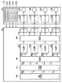
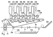
図1は、本実施例における電子写真方式カラー画像形成装置の、静電潜像作成に関係する各ブロックの構成を説明する図である。カラー画像形成装置は画像形成部101と画像処理部102により構成され、画像処理部102でビットマップ画像情報を生成し、それに基づき画像形成部101が記録媒体上への画像形成を行う。図2は、中間転写体28を採用したタンデム方式の電子写真方式を用いたカラー画像形成装置の断面図である。図1を用いて、電子写真方式のカラー画像形成装置における画像形成部101の動作を説明する。
FIG. 1 is a diagram for explaining the configuration of each block related to electrostatic latent image creation in the electrophotographic color image forming apparatus of this embodiment. The color image forming apparatus includes an
画像形成部101は、画像処理部102が処理した露光時間に応じて露光光を駆動し、静電潜像を形成して、この静電潜像を現像して単色トナー像を形成する。この単色トナー像を重ね合わせて多色トナー像を形成し、この多色トナー像を図2の記録媒体11へ転写してその記録媒体上の多色トナー像を定着させる。
The
図2の23Y,23M,23C,23Kは注入帯電器であり、Y,M,C,Kの色毎に感光体22Y,22M,22C,22Kを帯電させるために4個を備える構成である。また、各注入帯電器にはスリーブ23YS,23MS,23CS,23KSを備えている。
感光体22Y,22M,22C,22Kは、図示しない駆動モータの駆動力が伝達されて回転するもので、駆動モータは感光体22Y,22M,22C,22Kを画像形成動作に応じて反時計周り方向に回転させる。露光手段は、感光体22Y,22M,22C,22Kへスキャナ部24Y,24M,24C,24Kより露光光を照射し、感光体22Y,22M,22C,22Kの表面を選択的に露光することにより、静電潜像を形成するように構成している。
The
図2の現像器26Y,26M,26C,26Kは、前記静電潜像を可視化するために、Y,M,C,Kの色毎に現像を行う4個の現像器を備える構成で、各現像器には、スリーブ26YS,26MS,26CS,26KSが設けられている。なお、各々の現像器26は脱着が可能である。
The developing
図2の中間転写体28は、感光体22から単色トナー像を受け取るために時計周り方向に回転し、感光体22Y,22M,22C,22Kとその対向に位置する一次転写ローラ27Y,27M,27C,27Kの回転に伴って、単色トナー像が転写される。一次転写ローラ27に適当なバイアス電圧を印加すると共に感光体22の回転速度と中間転写体28の回転速度に差をつけることにより、単色トナー像が効率良く中間転写体28上に転写される。これを一次転写という。
The
更に、ステーション毎の単色トナー像は、中間転写体28上に重ね合わされる。重ね合わされた多色トナー像は、中間転写体28の回転に伴い二次転写ローラ29まで搬送される。同時に、記録媒体11が給紙トレイ21から二次転写ローラ29へ狭持搬送され、記録媒体11に中間転写体28上の多色トナー像が転写される。このとき、二次転写ローラ29に適当なバイアス電圧を印加することで、静電的にトナー像を転写する。これを二次転写という。二次転写ローラ29は、記録媒体11上に多色トナー像を転写している間、29aの位置で記録媒体11に当接し、印字処理後は29bの位置に離間する。
Further, the single color toner image for each station is superimposed on the
定着装置31は、記録媒体11に転写された多色トナー像を記録媒体11に溶融定着させるために、記録媒体11を加熱する定着ローラ32と記録媒体11を定着ローラ32に圧接させるための加圧ローラ33を備えている。定着ローラ32と加圧ローラ33は中空状に形成され、内部にそれぞれヒータ34、35が内蔵されている。定着装置31は、多色トナー像を保持した記録媒体11を定着ローラ32と加圧ローラ33により搬送するとともに、熱および圧力を加え、トナーを記録媒体11に定着させる。
The fixing
トナー定着後の記録媒体11は、その後図示しない排出ローラによって図示しない排紙トレイに排出して画像形成動作を終了する。クリーニング手段30は、中間転写体28上に残ったトナーをクリーニングするものであり、中間転写体28上に形成された4色の多色トナー像を記録媒体11に転写した後に残った廃トナーは、クリーナ容器に蓄えられる。
The
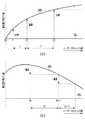
次に、図3、図4、図5を用いて、画像形成装置の色毎の走査線のプロファイル特性に関して説明する。図3において、(a)は画像形成装置のプロファイル特性として、レーザースキャン方向に対して上方(垂直方向)にずれている領域を示す図である。また、(b)は画像形成装置のプロファイル特性として、レーザースキャン方向に対して下方(垂直方向)にずれている領域を示す図である。301は理想的な走査線であり感光体22の回転方向に対して垂直に走査が行われる場合の特性を示す。
Next, scanning line profile characteristics for each color of the image forming apparatus will be described with reference to FIGS. 3, 4, and 5. In FIG. 3, (a) is a diagram showing a region shifted upward (perpendicular direction) with respect to the laser scanning direction as profile characteristics of the image forming apparatus. Further, (b) is a diagram showing a region shifted downward (perpendicular direction) with respect to the laser scanning direction as profile characteristics of the image forming apparatus.
なお、以下、説明におけるプロファイル特性は、画像処理部102で補正がなされるべき方向を前提として行うが、プロファイル特性としての定義は、これに限定されるものではない。つまり、画像形成部101のずれ方向として定義しておき、画像処理部102では、その逆特性の補正を行うように構成しても良い。図4にプロファイル定義による、画像処理部102で補正がなされるべき方向示す図と、画像形成部101のずれ方向を示す図の相関を示す。画像処理部102で補正がなされるべき方向として、図4(a)のようにプロファイル特性が示されている場合は、画像形成部101の曲がり特性は、その逆方向である図4(b)のようなものとなる。逆に、画像形成部101の曲がり特性として、図4(c)のプロファイル特性が示されている場合、画像処理部102で補正がなされるべき方向としては図4(d)のようになる。
Hereinafter, the profile characteristics in the description are performed on the premise of the direction to be corrected by the
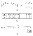
また、プロファイル特性のデータの保持の仕方としては、例えば図5に示すように、乗り換えポイントの主走査方向の画素位置と、次の乗り換えポイントまでの変化の方向性を保持するようにする。具体的には、図5を例にとれば、(a)のプロファイル特性に対し、乗り換えポイントがP1,P2,P3,・・・Pmが定義される。各乗り換えポイントの定義は、副走査方向に1画素ずれが発生するポイントであり、方向としては、次の乗り換えポイントまで上方向に変化する場合と下方向に変化する場合がある。 Further, as a method of retaining profile characteristic data, for example, as shown in FIG. 5, the pixel position in the main scanning direction of the transfer point and the directionality of the change up to the next transfer point are maintained. Specifically, taking FIG. 5 as an example, transfer points P1, P2, P3,... Pm are defined for the profile characteristics of FIG. The definition of each transfer point is a point where a one-pixel shift occurs in the sub-scanning direction, and the direction may change upward or down to the next transfer point.
例えば、乗り換えポイントP2は、次の乗り換えポイントP3まで、上方向に乗り換えを行うべきポイントとなる。したがって、P2における乗り換え方向は、(b)に示すように上方向(↑)となる。同様に、P3においても、次の乗り換えポイントP4までは上方向(↑)となる。乗り換えポイントP4における乗り換え方向は、これまでの方向とは異なり下方向(↓)となる。この方向のデータの保持の仕方としては、例えば、上方向を示すデータとして”1”、下方向を示すデータとして”0”とすれば、図5(c)のようになる。この場合、保持するデータ数は乗り換えポイント数と同じだけとなり、乗り換えポイント数がm個であるならば、保持するビット数もmビットとなる。 For example, the transfer point P2 is a point to be transferred upward until the next transfer point P3. Therefore, the transfer direction at P2 is upward (↑) as shown in (b). Similarly, in P3, the direction is up (↑) until the next transfer point P4. The transfer direction at the transfer point P4 is a downward direction (↓) unlike the previous direction. As a method of holding data in this direction, for example, if “1” is indicated as data indicating the upward direction and “0” is indicated as data indicating the downward direction, the data is as shown in FIG. In this case, the number of data to be held is only the same as the number of transfer points, and if the number of transfer points is m, the number of bits to be held is also m bits.
図3に戻り、302は感光体22の位置精度や径のずれ、および図2に示す各色のスキャナ部24(24C,24M,24Y,24K)における光学系の位置精度に起因した、傾きおよび曲がりの発生した実際の走査線を示す。画像形成装置は、その記録デバイス(記録エンジン)毎にこのプロファイル特性が異なり、更に、カラー画像形成装置の場合は、色毎にその特性が異なる。
Returning to FIG. 3,
次に、図3(a)を用いて、レーザースキャン方向に上方にずれている領域の乗り換えポイントに関して説明する。 Next, with reference to FIG. 3A, a transfer point in a region shifted upward in the laser scanning direction will be described.
本実施例における乗り換えポイントとは、副走査方向に1画素ずれているポイントのことを示す。つまり、図3(a)においては、上方への曲がり特性302上で副走査方向に1画素ずれているポイントであるP1、P2、P3が乗り換えポイントに相当する。なお、図3(a)においてはP0を基準としたものとして記載している。同図からもわかるように、乗り換えポイント間の距離(L1、L2)は、曲がり特性302が急激に変化している領域においては短くなり、緩やかに変化している領域においては長くなる。
The transfer point in the present embodiment indicates a point shifted by one pixel in the sub-scanning direction. That is, in FIG. 3A, P1, P2, and P3, which are points shifted by one pixel in the sub-scanning direction on the upward curve characteristic 302, correspond to transfer points. In FIG. 3A, P0 is used as a reference. As can be seen from the figure, the distances (L1, L2) between the transfer points are shorter in the region where the
次に、図3(b)を用いて、レーザースキャン方向に下方にずれている領域の乗り換えポイントに関して説明する。下方にずれている特性を示す領域においても、乗り換えポイントの定義は、副走査方向に1画素ずれているポイントのことを示す。つまり、図3(b)においては、下方への湾曲特性302上で副走査方向に1画素ずれているポイントであるPn、Pn+1が乗り換えポイントに相当する。図3(b)においても、図3(a)同様、乗り換えポイント間の距離(Ln、Ln+1)は、曲がり特性302が急激に変化している領域においては短くなり、緩やかに変化している領域においては長くなる。
Next, with reference to FIG. 3B, a transfer point in a region shifted downward in the laser scanning direction will be described. Even in a region that shows a characteristic that is shifted downward, the definition of a transfer point indicates a point that is shifted by one pixel in the sub-scanning direction. That is, in FIG. 3B, Pn and Pn + 1 which are points shifted by one pixel in the sub-scanning direction on the downward curve characteristic 302 correspond to transfer points. Also in FIG. 3B, as in FIG. 3A, the distance (Ln, Ln + 1) between the transfer points is short in the region where the
このように、乗り換えポイントは、画像形成装置がもつ曲がり特性302の変化度合い密接に関係する。よって、急激な曲がり特性をもつ画像形成装置においては、乗り換えポイント数は多くなり、逆に緩やかな曲がり特性をもつ画像形成装置においては、乗り換えポイント数が少なくなる。
As described above, the transfer point is closely related to the degree of change in the bending
既に説明している通り、画像形成装置がもつ曲がり特性は、色毎にも異なるため、乗り換えポイントの数および位置はそれぞれ異なる。この色間の相違が、中間転写体28上に全色のトナー像を転写した画像においてレジストレーションずれとなって現れることとなる。
As already described, since the bending characteristics of the image forming apparatus are different for each color, the number and position of transfer points are different. This difference between colors appears as a registration error in an image in which all color toner images are transferred onto the
次に、図1を用いて、カラー画像形成装置における画像処理部102の処理について説明する。画像生成部104は、不図示のコンピュータ装置等から受信する印刷データより、印刷処理が可能なラスターイメージデータを生成し、RGBデータおよび各画素のデータ属性を示す属性データとして画素毎に出力する。前記属性データは、文字、細線、CG、自然画といった属性を保持している。なお、画像生成部104は、コンピュータ装置等から受信した画像データではなく、カラー画像形成装置内部に読取手段を構成し、読取手段からの画像データを扱う構成としても良い。ここでいう読取手段とは、少なくともCCD(Charged Couple Device)あるいはCIS(Contact Image Sensor)を含むものである。読取手段に、読み取った画像データに対して所定の画像処理を行う処理部をあわせてもたせるように構成しても良い。また、カラー画像装置内部に構成せず、図示しないインターフェースを介して、前記読取手段からデータを受け取るように構成しても良い。
Next, processing of the
105は色変換部であり、前記RGBデータを画像形成部101のトナー色にあわせてCMYKデータに変換し、CMKYデータと属性データをビットマップメモリ106へ格納する。記憶部106は、画像処理部102に構成した第1の記憶部であり、印刷処理を行うラスターイメージデータを一旦格納するものである。なお、記憶部106は、1ページ分のイメージデータを格納するページメモリで構成しても良いし、複数ライン分のデータを記憶するバンドメモリとして構成しても良い。
A
107C,107M,107Y,107KはHT(ハーフトーニング)処理部であり、記憶部106から出力される属性データおよび各色のデータに1画素未満の乗り換えである補間処理と、ハーフトーニングを行う。HT処理部107での補間処理は、画像形成装置がもつ曲がり特性に対応した乗り換えポイントの前後画素を使用する。補間処理およびハーフトーニングの詳細については後述する。
108は、画像形成装置内部に構成した第2の記憶部であり、HT処理部107(107C,107M,107Y,107K)により処理されたN値化データを記憶する。なお、記憶部108以降の画像処理する画素位置が乗り換えポイントである場合、記憶部108から読み出される時点で、1画素分の乗り換えが行われる。HT処理前はM値データであったが、HTによりN値化(M>N)処理されたN値化データに対して1画素分の乗り換えが行なわれるため、処理コスト(演算能力、記憶部108のメモリ容量)が少なくて済む。なお、記憶部108で行われる1画素分の乗り換えの詳細については後述する。また、本実施例においては、第1記憶部106、第2記憶部108を別構成として説明したが、画像形成装置内部に共通の記憶部を構成するようにしても良い。
図12(a)は記憶部108が保持しているデータの状態を模式的に示す図である。図12(a)に示す通り、記憶部108が記憶している状態においては、画像処理部102としての乗り換え方向、あるいは画像形成部101の曲がり特性によらず、HT処理部107による処理後のデータが保持されている。図12に示す1201のラインが読み出される時点で、画像処理部102で補正されるべき方向としてのプロファイル特性が上方向の場合、図12(b)のように、乗り換えポイントを境界として、上方向に1画素分ずらされた状態となる。また、画像処理部102で補正されるべき方向としてのプロファイル特性が下方向の場合、ライン1201の画像データが、記憶部108から読み出された時点で、図12(c)のように、乗り換えポイントを境界として、下方向に1画素分ずらされた状態となる。
FIG. 12A is a diagram schematically illustrating the state of data held in the
113はパルス幅変調(PWM:Pulse Width Modulation)であり、記憶部108から1画素分の乗り換えを行って読み出された色毎の画像データに対して、スキャナ部115C,115M,115Y,115Kの露光時間へ変換される。そして、変換後の画像データは、画像形成部101の印字部115により出力される。
Reference numeral 113 denotes pulse width modulation (PWM). The image data for each color read out by changing one pixel from the
なお、図5により、既に説明をしたプロファイル特性データに関しては、画像形成部101内部に、画像形成装置がもつ特性として、装置内部に保持されている。そして、画像処理部102は、画像形成部101が保持しているプロファイル特性に応じて処理を行う(プロファイル116C,116M,116Y,116K)。
Note that the profile characteristic data already described with reference to FIG. 5 is held in the
次に、図6を用いて、前記画像処理部102のHT処理部107(107C,107M,107Y,107K)の動作について詳細に説明する。なお、107C,107M,107Y,107Kは全て同じ構成とすることができるため、以下にHT処理部107として説明する。
Next, the operation of the HT processing unit 107 (107C, 107M, 107Y, 107K) of the
HT処理部107は、CMYKデータから対応する色の画像データと属性データ(属性情報)を受け取り、連続階調補間処理部(第1の補間処理部)601とスクリーン処理部(第2の中間調処理部)603に画像データを渡す。画像データを受け取った連続階調補間処理部601は、ハーフトーニングされる前の連続階調を持つ画像データ(以下、連続階調画像)に対して1画素未満の乗り換えを行うための補間処理を実施する。連続階調補間処理部601での補間処理は、画像形成装置がもつ曲がり特性に対応した乗り換えポイントの前後画素を使用する。補間処理の詳細については後述する。
The
次に、誤差拡散処理部(第1の中間調処理部)602において、補間処理された連続階調画像を、より階調数の少ない面積階調を持つ画像データ(以下、面積階調画像)へと変換するために、誤差拡散法を用いたハーフトーニングを行う。すなわち、画像データの階調数をM値からN(M>N)値に変換する。誤差拡散法は、入力された画像データを所定の閾値と比較することによりN値化を行い、その際の画像データと閾値との差分を以降にN値化処理する周囲画素に対して拡散させる方法である。なお、本実施例において誤差拡散処理部は誤差拡散法を用いるが、それに限るものではなく、例えば平均誤差最少法や平均濃度保存法など、周期性が少なく、ドットが比較的分散するハーフトーニング方法であれば良い。 Next, in the error diffusion processing unit (first halftone processing unit) 602, the continuous tone image subjected to the interpolation processing is converted into image data having an area gradation with a smaller number of gradations (hereinafter referred to as an area gradation image). In order to convert to, halftoning using the error diffusion method is performed. That is, the number of gradations of the image data is converted from M value to N (M> N) value. In the error diffusion method, input image data is N-valued by comparing it with a predetermined threshold value, and the difference between the image data and the threshold value at that time is diffused to surrounding pixels to be N-valued thereafter. Is the method. In this embodiment, the error diffusion processing unit uses an error diffusion method. However, the error diffusion method is not limited thereto. For example, a halftoning method in which dots are relatively dispersed, such as an average error minimization method and an average density preservation method. If it is good.
また、スクリーン処理部603は、画像データを受け取り、連続階調画像を、より階調数の少ない面積階調画像へと変換するために、スクリーン処理によるハーフトーニングを行う。すなわち、画像データの階調数をM値からN(M>N)値に変換する。スクリーン処理は、複数の閾値が配置されたディザマトリックスから任意の閾値を読み出し、入力された画像データと閾値との比較を行うことでN値化するディザ法によるものである。電子写真方式のカラー画像形成装置においては、記録媒体上に安定したドット再現性を実現するために、ドットが集中するようなディザマトリックスが周期的に用いられる。
The
次に、面積階調補間処理部(第2の補間処理部)604は、スクリーン処理部でハーフトーニングされた面積階調画像に対して1画素未満の乗り換えを行うための補間処理を実施する。面積階調補間処理部604で行われる補間処理は、連続階調補間処理部601での補間処理と基本的には同じであるが、ハーフトーニングによって階調数が削減された面積階調画像に対して補間処理を行う点が異なる。連続階調補間処理部601での補間処理と同様に、面積階調補間処理部604は画像形成装置が持つ曲がり特性に対応した乗り換えポイントの前後画素を使用する。補間処理の詳細については後述する。
Next, the area gradation interpolation processing unit (second interpolation processing unit) 604 performs an interpolation process for changing the area gradation image halftoned by the screen processing unit to less than one pixel. The interpolation processing performed by the area gradation
最後に、セレクタ(選択部)605は、属性データに応じて、誤差拡散処理部602から出力される画像データと面積階調補間処理部604から出力される画像データとのどちらかを択一的に選択し、一方の画像データを出力する。本実施例においては、文字と細線の属性を持つ画素の場合に誤差拡散処理部602から出力された画像データを、それ以外のCGと自然画の属性を持つ画素の場合には面積階調補間処理部604から出力される画像データを選択して出力する。すなわち、セレクタ605は、比較的高周波成分が多い画像データに対しては誤差拡散処理部602から出力された第1の画像データを、比較的低周波成分が多い画像データに対しては面積階調補間処理部604から出力される第2の画像データを、選択して出力する。なお、これら属性データに対する画像データの選択はこれに限るものではなく、例えば自然画の属性を持つ画素の場合に誤差拡散処理部602から出力された画像データを出力しても良いことは言うまでもない。
Finally, the selector (selection unit) 605 selects either the image data output from the error
なお、図6の構成においては、セレクタ605が誤差拡散処理部602及び面積階調補間処理部604の後段に位置し、各部からの出力を選択する例を説明した。しかしながら、セレクタ605が誤差拡散処理部602及び面積階調補間処理部604の前段に位置し、属性に応じて各部に供給する画像データの出力を選択するよう制御する構成であってもよい。
In the configuration of FIG. 6, the example has been described in which the
次に、図7、図8、図9を用いて、前述の連続階調補間処理部601で補間処理、すなわち1画素未満の乗り換えを行なう処理について詳細に説明する。図7は、乗り換えポイントと本実施例における補間領域を模式的に示した図である。図8、図9は、連続階調補間処理部601の1画素未満の乗り換えを行う補間処理と、記憶部108で行う1画素分の乗り換えとを模式的に表した図である。
Next, with reference to FIGS. 7, 8, and 9, the above-described continuous tone
図7は、レーザースキャン方向に対する、画像形成装置の曲がり特性を示す図である。領域1は画像処理部102として、上向きに補正を行わなければならない領域であり、反対に、領域2は画像処理部102として下向きに補正を行わなければならない領域であるものとする。なお、以降の補間処理の説明においては、説明の便宜上、乗り換えポイント間の最小間隔を16画素とするが、本発明はこれに限られるものではない。つまり、任意の画素数間隔にしても良いし、回路構成縮小のために2のべき乗の画素間隔にしても良い。
FIG. 7 is a diagram illustrating the bending characteristics of the image forming apparatus with respect to the laser scanning direction. The
図7の例における、乗り換えポイントPa前後の補間処理前画像、すなわち、連続階調補間処理部601に入力される画像データを図8(a)に示す。注目ラインは、図示する3ライン分の画像データの中央ラインである。
The pre-interpolation image before and after the transfer point Pa in the example of FIG. 7, that is, image data input to the continuous tone
連続階調補間処理部601は、連続階調画像の画像データに対して、1画素未満の乗り換えのために補間処理を行う。領域1における、補間の方向は上向きであるため、後ライン側から前ライン側に向けて補間が行なわれることになるため、注目ラインの補間処理は、注目ラインと後ラインとの画像データの重み付け演算により行う。本説明における重み付けは、図8(b)に示す通り、演算対象となる注目ラインと後ラインにおける副走査方向2画素の総和が、乗り換えポイントの最小値に合わせ16となるように記載するが、本発明における重み付け係数の総和は16に限定されるものではない。演算に用いる回路の縮小化のために、2のべき乗となるようにしても良いし、より精度を上げるため、任意の係数で演算できるようにしても良い。また、重み付けの構成として、1画素単位に重み付け係数を変えるようにしても良いし、図8に示すように、複数画素単位で共通の重み付け係数を用いるようにしても良い。更には、重み付け係数の値に応じて、対応させる画素数を可変にするようにしても良い。なお、乗り換えポイントの定義は、レーザースキャン方向に対して、副走査方向に1画素ずれる位置が該当するため、補間の際の基準位置は左側として以降の説明をする。例えば、図8の例では、PaからPbまでの領域においては、補間の際の基準位置は左側であるPaとなる。
The continuous tone
補間に用いる演算式を(式1)に記す。
(補間画素値)=W1×(注目ラインの1ライン前画素値)+W2×(注目ライン画素値)+W3×(注目ラインの1ライン後画素値) ・・・・・(式1)
※W1、W2、W3は任意の重み付け係数
本説明の例において、上記(式1)により得られる補間画素の概念図を図8(c)に示す。図8(c)は、図8(a)に示した画像データに対してラインを1行ずつずらして上記演算をして得られた補間画素値を示している。(式1)による補間により、乗り換えポイントPaの前では、乗り換えポイントPaに近い画素ほど、後ラインの画素値の影響を受け、乗り換えポイントPaから遠くなる画素ほど、注目ライン、すなわち、黒データラインの影響を強く受ける。
An arithmetic expression used for the interpolation is shown in (Expression 1).
(Interpolated pixel value) = W1 × (pixel value one line before the target line) + W2 × (pixel value of the target line) + W3 × (pixel value after one line of the target line) (Equation 1)
* W1, W2, and W3 are arbitrary weighting coefficients. FIG. 8C shows a conceptual diagram of the interpolation pixel obtained by the above (Equation 1) in the example of the present description. FIG. 8C shows interpolated pixel values obtained by performing the above calculation by shifting the lines one by one with respect to the image data shown in FIG. By interpolation according to (Equation 1), before the transfer point Pa, the pixels closer to the transfer point Pa are affected by the pixel value of the rear line, and the pixels farther from the transfer point Pa are the target line, that is, the black data line. Strongly influenced by.
また、乗り換えポイントPaの後ろの画素では、乗り換えポイントPaに近い画素ほど、注目ラインの影響を強く受け、乗り換えポイントPaから遠い画素ほど、注目ラインの後ラインの影響を受ける結果となる。 Further, in the pixels behind the transfer point Pa, the pixels closer to the transfer point Pa are more affected by the attention line, and the pixels farther from the transfer point Pa are affected by the rear line of the attention line.
次に、誤差拡散処理部602において、誤差拡散法によるハーフトーニングが行われ、図8(d)に示すように連続階調画像が面積階調画像に変換される。このとき、誤差拡散法では、ハーフトーニングによって面積階調のドットが比較的分散し、かつ周期性が少なく形成されるため、補間処理によって生まれる中間濃度のドットが途切れにくいことがわかる。
Next, in the error
最後に、図8(e)に示すように、記憶部108において、1画素単位の画素乗り換え処理が記憶部108の出力時に行われる。1画素を超える乗り換え処理は記憶部108から読み出す時点で行うため、これまで現れていた乗り換えポイントPa前後の大きな段差はここで無くなることになる。
Finally, as shown in FIG. 8E, in the
次に、下向きに補正を行わなければならない図7の領域b部分に関して図9を用いて説明する。下向きに補正する場合においては、前ライン側から後ライン側に向けて補間が行なわれることになるため、補正画素値の演算に用いる重み付け係数が、注目ラインと注目ラインの前ラインに設定されることとなる。 Next, the region b in FIG. 7 that must be corrected downward will be described with reference to FIG. In the downward correction, since interpolation is performed from the front line side to the rear line side, the weighting coefficient used for calculating the corrected pixel value is set to the attention line and the preceding line of the attention line. It will be.
図9(a)には、連続階調補間処理部601に入力される時点の画像データを示す。下向きの補正を行う場合のW1、W2、W3の値は図9(b)に示す通りであり、説明の便宜上、上向き補正処理時と同様、重み付け係数の総和が16となるようにしている。下向き補正時に対しても、(式1)を適用すると、乗り換えポイントPcを境界として、補正画素値が求まる。つまり、乗り換えポイントPcの前では、乗り換えポイントに近い画素ほど、前ラインの画素値の影響を受け、乗り換えポイントPcから遠くなる画素ほど、注目ラインの影響を強く受ける。また、乗り換えポイントPcの後ろの画素では、乗り換えポイントPcに近い画素ほど、注目ラインの影響を受け、乗り換えポイントPcから遠い画素ほど、注目ラインの前ラインの影響を受ける結果となる(図9(c))。
FIG. 9A shows image data at the time of input to the continuous tone
次に、誤差拡散処理部602において、誤差拡散法によるハーフトーニングが行われ、図9(d)に示すように連続階調画像が面積階調画像に変換される。このときも、誤差拡散法の効果により、補間処理によって生まれる中間濃度の画素が途切れにくい。
Next, in the error
最後に、図9(e)に示すように、記憶部108において、1画素単位の乗り換え処理が記憶部108の出力時に行われる。1画素を超える乗り換え処理は記憶部108から読み出す時点で行うため、これまで現れていた乗り換えポイントPa前後の大きな段差はここで無くなることになる。
Finally, as shown in FIG. 9E, in the
このように、連続階調補間処理部601の補間処理により、補間の方向が上方向であっても、下方向であっても、主走査方向に連続する画素データが、1画素を超える乗り換え処理段差によって、大きな段差として現れることが防止される。
As described above, by the interpolation processing of the continuous tone
次に、図7、図10、図11を用いて、前述の面積階調補間処理部604で行われる補間処理について詳細に説明する。
Next, the interpolation process performed by the area gradation
図7の例における、乗り換えポイントPa前後の補間処理前画像、すなわち、面積階調補間処理部604に入力される画像データを図10(a)に示す。注目ラインは、図示する3ライン分の画像データの中央ラインである。
The pre-interpolation image before and after the transfer point Pa in the example of FIG. 7, that is, the image data input to the area gradation
面積階調補間処理部604は、面積階調画像に変換された画像データに対して注目ライン上に1画素未満の乗り換えのために補間処理を行う。領域1における、補間の方向は上向きであるため、注目ラインの補間処理には、後ラインの画像データとの重み付け演算により行う。本実施例における重み付けは図10(b)に示す通りであり、補間処理によって出力される画像データを図10(c)に示す。なお、面積階調補間処理部604における補間処理の内容については上記連続階調補間処理部601と同様のため、ここでの説明は省く。最後に、図10(d)に示すように、記憶部108において、1画素単位の乗り換え処理が記憶部108の出力時に行われる。1画素を超える乗り換え処理は記憶部108から読み出す時点で行うため、これまで現れていた乗り換えポイントPa前後の大きな段差はここで無くなることになる。
The area gradation
次に、下向きに補正を行わなければならない図7の領域b部分に関して図11を用いて説明する。下向きに補正する場合においては、補正画素値の演算に用いる重み付け係数が、注目ラインと注目ラインの前ラインに設定されることとなる。 Next, the region b in FIG. 7 that must be corrected downward will be described with reference to FIG. In the case of correcting downward, the weighting coefficient used for calculating the corrected pixel value is set to the attention line and the previous line of the attention line.
図11(a)には、面積階調補間処理部604に入力される時点の画像データを示す。下向きの補正を行う場合のW1、W2、W3の値は図11(b)に示す通りであり、面積階調補間処理部604によって補間処理がなされ、出力される画像データを図11(c)に示す。なお、面積階調補間処理部604における補間処理の内容については上記連続階調補間処理部601と同様のため、ここでの説明は省く。最後に、図9(d)に示すように、記憶部108において、1画素単位の乗り換え処理が記憶部108の出力時に行われる。1画素を超える乗り換え処理は記憶部108から読み出す時点で行うため、これまで現れていた乗り換えポイントPa前後の大きな段差はここで無くなることになる。
FIG. 11A shows image data at the time of input to the area gradation
このように、面積階調補間処理部604の補間処理により、補間の方向が上方向であっても、下方向であっても、主走査方向に連続する画素データが、1画素を超える乗り換え処理段差によって、大きな段差として現れることが防止される。
In this way, by the interpolation processing of the area gradation
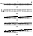
次に、図13と図14に、本実施例における処理結果を示す。 Next, FIG. 13 and FIG. 14 show the processing results in this embodiment.
図13は、50%の濃度で均一に塗られた画像データに対して、補間処理とハーフトーニングを様々な順序で処理した結果の一例である。図14は、100%の濃度の細線が描かれた画像データに対して、補間処理とハーフトーニングを様々な順序で処理した結果の一例である。 FIG. 13 is an example of the result of processing interpolation processing and halftoning in various orders on image data uniformly applied at a density of 50%. FIG. 14 is an example of a result of processing interpolation processing and halftoning in various orders on image data on which a thin line having a density of 100% is drawn.
図13(a)は、前記画像データを誤差拡散処理した後に、1画素未満の乗り換えを行う補間処理を実施した画像データの一例である。図13(a)は、本実施例とは異なり、誤差拡散処理後の面積階調画像に補間処理を行っている。また、図13(b)は、本実施例で説明した通り誤差拡散処理する前の連続階調画像に対して補間処理を行い、その後に誤差拡散処理を行った画像データの一例である。この両者を比較すると、図13(a)では全面が均一な濃度であるにも関わらず、1301と1302の領域でドット形状が全く異なっている。これは、誤差拡散法によって形成されるドットが比較的分散していることによるもので、補間処理によってその形状を大きく変えやすいがために起こる。領域1301と領域1302の間で起こるこれらドット形状の変化は、電子写真方式の画像形成装置においては、大きな濃度の違いとして現れてしまう。一方で、図13(b)では全面ドット形状に大きな変化がないことから、どの領域でも濃度が変化せず均一な濃度再現を行うことができる。
FIG. 13A is an example of image data that has been subjected to an error diffusion process on the image data and then subjected to an interpolation process for switching less than one pixel. In FIG. 13A, unlike the present embodiment, interpolation processing is performed on the area gradation image after the error diffusion processing. FIG. 13B is an example of image data obtained by performing interpolation processing on a continuous tone image before error diffusion processing as described in the present embodiment and then performing error diffusion processing. Comparing the two, in FIG. 13A, the dot shape is completely different in the
また、図13(c)は、本実施例で説明した通りスクリーン処理した後の面積階調画像に対して補間処理を行った画像データの一例である。図13(d)は、スクリーン処理前の連続階調画像に対して補間処理を行い、その後にスクリーン処理を行った画像データの一例である。この両者を比較すると、図13(c)では領域1303と領域1304でドット形状が若干変化しているもののドット形状を崩すことはなく、図13(c)と図13(d)の間で大きな違いがないことがわかる。これは、スクリーン処理によって形成されるドットが集中しており、十分に大きいために補間処理の影響を受けにくいことによる。
FIG. 13C is an example of image data obtained by performing interpolation processing on the area gradation image after screen processing as described in the present embodiment. FIG. 13D is an example of image data obtained by performing interpolation processing on a continuous tone image before screen processing and then performing screen processing. Comparing the two, in FIG. 13C, although the dot shape is slightly changed in the
また、図14(a)は図13(a)と同様に誤差拡散処理で変換した面積階調画像に補間処理を行ったもの、図14(b)は図13(b)と同様に連続階調画像に補間処理を行った後、誤差拡散処理を行ったものである。図14(c)は図13(c)と同様にスクリーン処理で変換した面積階調画像に補間処理を行ったもの、図14(d)は図13(d)と同様に連続階調画像に補間処理を行った後、スクリーン処理を行ったものである。 FIG. 14A shows an example in which interpolation processing is performed on the area gradation image converted by the error diffusion processing as in FIG. 13A, and FIG. 14B shows continuous levels as in FIG. 13B. An error diffusion process is performed after performing an interpolation process on the toned image. FIG. 14C shows an area gradation image converted by screen processing as in FIG. 13C, and FIG. 14D shows a continuous gradation image as in FIG. 13D. The screen processing is performed after the interpolation processing.
図14(b)は、前述した通り、補間処理後に誤差拡散処理を行っても、補間処理によって生まれる中間濃度の画素が途切れにくく自然に乗り換えが行われている。一方で、図14(d)は、補間処理後にスクリーン処理を行っているため、補間処理によって生まれる中間濃度部分がスクリーン処理の影響で途切れたり、大きなエッジ部のガタつきとして見えてしまう。これは、スクリーン処理によって形成されるドットが周期的に凝集した形で形成されることによる。なお、図14(c)では、スクリーン処理後に補間処理を行っているため、このような現象は生じない。 In FIG. 14B, as described above, even if the error diffusion process is performed after the interpolation process, the intermediate density pixels generated by the interpolation process are not easily interrupted and are naturally switched. On the other hand, in FIG. 14D, since the screen processing is performed after the interpolation processing, the intermediate density portion generated by the interpolation processing is interrupted due to the influence of the screen processing, or appears to be loose at a large edge portion. This is because the dots formed by the screen processing are formed in a periodically aggregated form. In FIG. 14C, since the interpolation process is performed after the screen process, such a phenomenon does not occur.
以上のことから、本実施例によれば、誤差拡散処理に対してはハーフトーニングよりも前の連続階調画像に対して補間処理を行うため、濃度が均一に塗られた画像データに対して均一な濃度を再現することができ、細線の画像データが途切れることもない。また、スクリーン処理に対してはハーフトーニングよりも後の面積階調画像に対して補間処理を行うため、細線の画像データを途切れさせることなく再現することができる。さらに、1画素分の乗り換えは、常に連続階調画像に比べてデータ量の少ない面積階調画像に対して行うため、1画素分の乗り換えにかかるコストを最小限に抑えることができる。 From the above, according to the present embodiment, the error diffusion process is performed on the continuous tone image before the halftoning, so that the image data with uniform density is applied to the image data. Uniform density can be reproduced, and fine line image data is not interrupted. Further, since the interpolation process is performed on the area gradation image after the halftoning for the screen processing, it is possible to reproduce the thin line image data without interruption. Furthermore, since the transfer for one pixel is always performed for the area gradation image having a smaller data amount than the continuous gradation image, the cost for the transfer for one pixel can be minimized.
本実施例において、前述の実施例とは図1のHT処理部107の構成・動作のみが異なる。そのため、前述の実施例と同様の部分に関しては、同一番号を付けて省略し、異なる部分のみを以下に説明する。実施例1においては、ハーフトーニングに誤差拡散処理を用いる場合には連続階調補間処理を行い、ハーフトーニングにスクリーン処理を用いる場合には面積階調補間処理を行う例について説明した。実施例2においては、ハーフトーニングにスクリーン処理を行う場合において、高線数スクリーン処理を行う場合には連続階調補間処理を行い、低線数スクリーン処理を行う場合には面積階調補間処理を行う例について説明する。
In this embodiment, only the configuration and operation of the
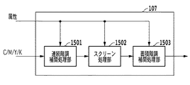
以下に、図15と図16を用いて、本実施例におけるHT処理部107の構成を説明する。
Hereinafter, the configuration of the
図15は、本実施例におけるHT処理部107のブロック図である。
FIG. 15 is a block diagram of the
HT処理部107は、CMYKデータから対応する色の画像データと属性データを受け取り、連続階調補間処理部(第3の補間処理部)1501に画像データと属性データを渡す。連続階調補正処理部1501は、連続階調画像に1画素未満の乗り換えを行う補間処理を実施する。また、属性データに応じて補間処理を行わずに出力する機能も有する。なお、補間処理の詳細については、前記連続階調補間処理部601と同様であるため、ここでの説明を省く。
The
次に、スクリーン処理部(第3の中間調処理部)1502は、画像データと属性データを受け取り、連続階調画像をより階調数の少ない面積階調画像へと変換するために、画像データにスクリーン処理によるハーフトーニングを行う。また、スクリーン処理部1502は、複数のディザマトリックスを保持しており、属性データに従って任意のディザマトリックスを選択して使用する。
Next, the screen processing unit (third halftone processing unit) 1502 receives the image data and the attribute data, and converts the continuous tone image into an area gradation image having a smaller number of gradations. And halftoning by screen processing. The
次に、面積階調補間処理部(第4の補間処理部)1503は、ハーフトーニングによって階調数が減じられた面積階調画像に1画素未満の乗り換えを行う補間処理を実施する。面積階調補間処理部1503も属性データに応じて補間処理を行わずに出力する機能を有する。なお、補間処理の詳細については、前記面積階調補間処理部604と同様であるため、ここでの説明を省く。
Next, an area gradation interpolation processing unit (fourth interpolation processing unit) 1503 performs an interpolation process for changing the area gradation image in which the number of gradations is reduced by halftoning to less than one pixel. The area gradation
次に、図16を用いて、本実施例におけるHT処理部107の動作を詳細に説明する。
Next, the operation of the
図16は、HT処理部107の動作を示すフローチャートである。
FIG. 16 is a flowchart showing the operation of the
まず、ステップS1601において、連続階調補間処理部1501は、属性データからスクリーン処理部1502で適用されるディザマトリックスの空間周波数特性を判断し、連続階調画像に対して補間処理を行うか否かを決定する。前記属性データは、画像データの属性を示しており、文字、細線、CG、自然画の情報を画素ごとに保持している。スクリーン処理部1502は、それら属性データに対して複数のディザマトリックスの中から一つを選択してスクリーン処理を行う。本実施例においては、文字、細線の属性を持つ画像データに対しては、高線数ディザマトリックスを、それら以外のCGと自然画の画像データに対しては、低線数ディザマトリックスを適用する。高線数ディザマトリックスは高い空間周波数特性(第1の空間周波数特性)を持ち、低線数ディザマトリックスは低い空間周波数特性(第2の空間周波数特性)を持つ。このため、高い空間周波数特性を持つ場合には、ステップS1602に、そうでない場合にはステップS1604に進む。本実施例において、高い空間周波数特性とはスクリーン線数が200線を越えるディザマトリックスを指す。
First, in step S1601, the continuous tone
次に、ステップS1602において、連続階調補間処理部1501は、ハーフトーニング前の連続階調画像に対して、前述の1画素未満の乗り換えを行う補間処理を実施する。
Next, in step S1602, the continuous tone
次に、ステップS1603において、スクリーン処理部1502は、補間処理が施された連続階調画像に対して、高線数ディザマトリックスを用いてスクリーン処理を行い、面積階調画像に変換する。
Next, in step S1603, the
また、ステップS1604において、スクリーン処理部1502は、補間処理が施されていない連続階調画像に対して、低線数ディザマトリックスを用いてスクリーン処理を行い、面積階調画像に変換する。
In step S1604, the
次に、ステップS1605において、面積階調補間処理部1503は、低線数ディザマトリックスを用いて変換された面積階調画像に、前述の1画素未満の乗り換えを行う補間処理を実施する。
Next, in step S1605, the area gradation
なお、本実施例において、属性データは文字、細線、CG、自然画と説明したが、これに限るものではなく、例えば図や表など、他の属性を持っても良い。また、本実施例において、ディザマトリックスは低線数や高線数の二種類としたが、それら以外にも複数持ってよく、また、FMスクリーンのようなドット分散型のディザマトリックスを用いても良い。また、空間周波数特性をディザマトリックスのスクリーン線数によって判断しているが、例えば、離散的フーリエ変換などを行って空間周波数特性を求めて判断してもよい。本実施例において、高い空間周波数特性は200線以上と説明したが、用いる画像形成装置によっては特性が大きくことなるため、連続階調画像への補間処理で濃度ムラが発生するか否かによって高い空間周波数を判断しても良い。 In the present embodiment, the attribute data has been described as characters, fine lines, CG, and natural images. However, the present invention is not limited to this, and may have other attributes such as diagrams and tables. In this embodiment, the dither matrix has two types of low lines and high lines. However, a plurality of other dither matrices may be used, or a dot dispersion type dither matrix such as an FM screen may be used. good. Further, although the spatial frequency characteristic is determined by the number of screen lines of the dither matrix, for example, the spatial frequency characteristic may be determined by performing discrete Fourier transform or the like. In this embodiment, the high spatial frequency characteristic is described as 200 lines or more. However, depending on the image forming apparatus to be used, the characteristic is large. Therefore, the high spatial frequency characteristic is high depending on whether density unevenness occurs in the interpolation process to the continuous tone image. The spatial frequency may be determined.
次に、図13と図14、図17、図18に、本実施例における処理結果を示す。 Next, FIG. 13, FIG. 14, FIG. 17, and FIG. 18 show the processing results in this embodiment.
図17は、50%の濃度で均一に塗られた画像データに対して、補間処理とハーフトーニングを様々な順序で処理した結果の一例である。図18は、100%の濃度の細線が描かれた画像データに対して、補間処理とハーフトーニングを様々な順序で処理した結果の一例である。 FIG. 17 shows an example of the result of processing interpolation processing and halftoning in various orders on image data uniformly applied at a density of 50%. FIG. 18 is an example of a result of processing interpolation processing and halftoning in various orders on image data on which a thin line having a density of 100% is drawn.
図13(c)は、134線のディザマトリックスを用いてスクリーン処理した後の面積階調画像に対して補間処理を行った画像データの一例である。図13(d)は、134線のディザマトリックスを用いてスクリーン処理前の連続階調画像に対して補間処理を行い、その後にスクリーン処理を行った画像データの一例である。この両者を比較すると、図13(c)では領域1303と領域1304でドット形状が若干変化しているもののドット形状を崩すことはなく、図13(c)と図13(d)の間で大きな違いがないことがわかる。これは、スクリーン処理によって形成されるドットが集中しており、十分に空間周波数特性が低いために補間処理の影響を受けにくいことによる。
FIG. 13C shows an example of image data obtained by performing interpolation processing on the area gradation image after screen processing using a 134-line dither matrix. FIG. 13D is an example of image data obtained by performing interpolation processing on a continuous tone image before screen processing using a 134-line dither matrix and then performing screen processing. Comparing the two, in FIG. 13C, although the dot shape is slightly changed in the
一方で、図17(a)は、前記画像データを212線のディザマトリックスを用いてスクリーン処理した後に、1画素未満の乗り換えを行う補間処理を実施した画像データの一例である。図17(a)は、本実施例とは異なり、高線数ディザマトリックスを用いたスクリーン処理後の面積階調画像に補間処理を行っている。また、図17(b)は、本実施例で説明した通り高線数ディザマトリックスを用いたスクリーン処理前の連続階調画像に対して補間処理を行い、その後にスクリーン処理を行った画像データの一例である。この両者を比較すると、図17(a)では全面が均一な濃度であるにも関わらず、1701と1702の領域でドット形状が全く異なっている。これは、高線数ディザマトリックスによって形成されるドットが高い空間周波数特性を持つことによるもので、補間処理によってその形状を大きく変えやすいがために起こる。領域1701と領域1702の間で起こるこれらドット形状の変化は、電子写真方式の画像形成装置においては、大きな濃度の違いとして現れてしまう。
On the other hand, FIG. 17A is an example of image data that has been subjected to screen processing using a 212-line dither matrix and then subjected to interpolation processing for changing less than one pixel. In FIG. 17A, unlike the present embodiment, interpolation processing is performed on the area gradation image after the screen processing using the high line number dither matrix. FIG. 17B shows the image data obtained by performing the interpolation processing on the continuous tone image before the screen processing using the high line number dither matrix as described in the present embodiment, and then performing the screen processing. It is an example. Comparing the two, in FIG. 17A, the dot shape is completely different in the
また、図18(a)は図17(a)と同様に高線数ディザマトリックスを用いたスクリーン処理で変換した面積階調画像に補間処理を行ったものである。図18(b)は図17(b)と同様に連続階調画像に補間処理を行った後、高線数ディザマトリックスを用いたスクリーン処理を行ったものである。 FIG. 18A shows the result of performing interpolation processing on the area gradation image converted by the screen processing using the high line number dither matrix, as in FIG. 17A. FIG. 18B shows the result of performing screen processing using a high line number dither matrix after performing interpolation processing on a continuous tone image in the same manner as FIG. 17B.
図18(b)は、補間処理後にスクリーン処理を行っても、十分に高い空間周波数を持つディザマトリックスが用いられているため、補間処理によって生まれる中間濃度の画素が途切れにくく自然に乗り換えが行われている。一方で、図14(d)は、補間処理後に低い空間周波数を持つディザマトリックスでスクリーン処理を行っているため、補間処理によって生まれる中間濃度部分がスクリーン処理の影響で途切れたり、大きなエッジ部のガタつきとして見えてしまう。これは、スクリーン処理によって形成されるドットが低い空間周波数特性で凝集したことによる。なお、図14(c)では、スクリーン処理後に補間処理を行っているため、このような現象は生じない。 In FIG. 18B, even if the screen processing is performed after the interpolation processing, a dither matrix having a sufficiently high spatial frequency is used, so that the intermediate density pixels generated by the interpolation processing are not easily interrupted and are naturally switched. ing. On the other hand, in FIG. 14D, since the screen processing is performed with a dither matrix having a low spatial frequency after the interpolation processing, an intermediate density portion generated by the interpolation processing is interrupted by the influence of the screen processing, or a large edge portion has a backlash. It looks as if it is a tsuke. This is due to the fact that the dots formed by the screen processing aggregated with low spatial frequency characteristics. In FIG. 14C, since the interpolation process is performed after the screen process, such a phenomenon does not occur.
以上のことから、本実施例によれば、スクリーン処理の空間周波数特性を判断し、高い空間周波数特性であればハーフトーニングよりも前の連続階調画像に対して補間処理を行う。このため、濃度が均一に塗られた画像データに対して均一な濃度を再現することができ、細線の画像データが途切れることもない。また、低い空間周波数特性であればハーフトーニングよりも後の面積階調画像に対して補間処理を行うため、細線の画像データを途切れさせることなく再現することができる。さらに、1画素分の乗り換えは、常に連続階調画像に比べてデータ量の少ない面積階調画像に対して行うため、1画素分の乗り換えにかかるコストを最小限に抑えることができる。 From the above, according to the present embodiment, the spatial frequency characteristic of the screen processing is determined, and if the spatial frequency characteristic is high, the interpolation process is performed on the continuous tone image before halftoning. For this reason, a uniform density can be reproduced with respect to image data with a uniform density, and the thin line image data is not interrupted. Also, if the spatial frequency characteristic is low, the interpolation processing is performed on the area gradation image after halftoning, so that the image data of the thin line can be reproduced without interruption. Furthermore, since the transfer for one pixel is always performed for the area gradation image having a smaller data amount than the continuous gradation image, the cost for the transfer for one pixel can be minimized.
なお、上記各実施例においては、トナーの色数と同数の現像機および感光ドラムを備え、画像搬送ベルト上や、記録媒体上に順次異なる色の画像を転写するタンデム方式のカラー画像形成装置を例に説明した。これは、タンデム方式のカラー画像形成装置にはトナーの色数と同数のレーザなどが用いられるために、レジストレーションずれが生じやすいからである。しかしながら、本発明は、モノクロやカラーを問わず、レーザを用いる画像形成装置のいずれにも適用可能であることは言うまでもない。 In each of the above embodiments, a tandem color image forming apparatus that includes the same number of developing devices and photosensitive drums as the number of colors of toner and sequentially transfers images of different colors onto an image conveying belt or a recording medium. Explained in the example. This is because a tandem type color image forming apparatus uses the same number of lasers as the number of colors of toner, and registration deviation is likely to occur. However, it goes without saying that the present invention can be applied to any image forming apparatus using a laser regardless of whether it is monochrome or color.
<その他の実施例>
また、本発明は、以下の処理を実行することによっても実現される。即ち、上述した実施形態の機能を実現するソフトウェア(プログラム)を、ネットワーク又は各種記憶媒体を介してシステム或いは装置に供給し、そのシステム或いは装置のコンピュータ(またはCPUやMPU等)がプログラムを読み出して実行する処理である。
<Other examples>
The present invention can also be realized by executing the following processing. That is, software (program) that realizes the functions of the above-described embodiments is supplied to a system or apparatus via a network or various storage media, and a computer (or CPU, MPU, or the like) of the system or apparatus reads the program. It is a process to be executed.
107 HT処理部
601 連続階調補間処理部
602 誤差拡散処理部
603 スクリーン処理部
604 面積階調補間処理部
605 セレクタ
107
Claims (13)
前記1画素未満の画素乗り換えが行なわれた画像データの階調数をM値からN(M>N)値に変換する中間調処理部と、
1画素未満の画素乗り換えが行なわれ、かつN値化された画像データに対して1画素単位の画素乗り換えを行なう乗り換え処理部と
を備えることを特徴とする画像形成装置。 An interpolation processing unit for performing pixel transfer of less than one pixel in image data having M-value gradations;
A halftone processing unit that converts the number of gradations of image data that has undergone pixel transfer of less than one pixel from an M value to an N (M> N) value;
An image forming apparatus comprising: a transfer processing unit that performs pixel transfer of less than one pixel and performs pixel transfer in units of one pixel for N-valued image data.
前記第1の補間処理部において1画素未満の画素乗り換えが行なわれた画像データの階調数を、周期性が少ない変換方法でM値からN(M>N)値に変換する第1の中間調処理部と、
M値の階調数を有する画像データの階調数を、前記第1の中間調処理部よりも周期性が多い変換方法でM値からN値に変換する第2の中間調処理部と、
前記第2の中間調処理部においてN値に変換された画像データにおける1画素未満の画素乗り換えを行なう第2の補間処理部と、
1画素未満の画素乗り換えが行なわれ、かつN値化された画像データに対して1画素単位の画素乗り換えを行なう乗り換え処理部と
を備えることを特徴とする画像形成装置。 A first interpolation processing unit for performing pixel transfer of less than one pixel in image data having M-value gradation numbers;
A first intermediate for converting the number of gradations of image data that has undergone pixel transfer of less than one pixel in the first interpolation processing unit from an M value to an N (M> N) value by a conversion method with less periodicity. A tone processing unit;
A second halftone processing unit that converts the number of gradations of image data having M number of gradations from an M value to an N value by a conversion method having a greater periodicity than the first halftone processing unit;
A second interpolation processing unit that performs a pixel change of less than one pixel in the image data converted into an N value in the second halftone processing unit;
An image forming apparatus comprising: a transfer processing unit that performs pixel transfer of less than one pixel and performs pixel transfer in units of one pixel for N-valued image data.
前記補間処理部において前記1画素未満の画素乗り換えが行なわれた場合に、該1画素未満の画素乗り換えが行なわれたM値の画像データを前記第1の空間周波数特性を有するN値の画像データに変換し、M値からN値へ階調数が変換される画像データに用いられる空間周波数特性が所定の値より低い第2の空間周波数特性である場合に、1画素未満の画素乗り換えが行なわれていないM値の画像データを前記第2の空間周波数特性を有するN値の画像データに変換する中間調処理部と、
前記中間調処理部で変換された前記第2の空間周波数特性を有するN値の画像データにおける1画素未満の画素乗り換えを行なう第2の補間処理部と
前記1画素未満の画素乗り換えが行なわれ、かつN値化された画像データに対して1画素単位の画素乗り換えを行なう乗り換え処理部と
を備えることを特徴とする画像形成装置。 When the spatial frequency characteristic used for the image data in which the gradation number is converted from the M value to the N (M> N) value is the first spatial frequency characteristic higher than a predetermined value, the gradation number of the M value is set. An interpolation processing unit for performing pixel transfer of less than one pixel in the image data having;
When the interpolation processing unit changes the pixel of less than one pixel, the M-value image data having the pixel change of less than one pixel is converted to N-value image data having the first spatial frequency characteristic. If the spatial frequency characteristic used for the image data converted to M value and converted from the M value to the N value is the second spatial frequency characteristic lower than a predetermined value, the pixel change of less than one pixel is performed. A halftone processing unit that converts M-value image data that has not been converted into N-value image data having the second spatial frequency characteristic;
A second interpolation processing unit that performs pixel transfer of less than one pixel in the N-value image data having the second spatial frequency characteristic converted by the halftone processing unit, and pixel transfer of less than one pixel is performed, An image forming apparatus comprising: a transfer processing unit that performs pixel transfer in units of one pixel for N-valued image data.
前記1画素未満の画素乗り換えが行なわれた画像データの階調数をM値からN(M>N)値に変換する中間調処理ステップと、
1画素未満の画素乗り換えが行なわれ、かつN値化された画像データに対して1画素単位の画素乗り換えを行なう乗り換え処理ステップと
を備えることを特徴とする画像形成方法。 An interpolation processing step of performing pixel transfer of less than one pixel in image data having M-value gradations;
A halftone processing step of converting the number of gradations of the image data subjected to the pixel change of less than one pixel from an M value to an N (M> N) value;
An image forming method, comprising: a transfer processing step in which a pixel change of less than one pixel is performed and a pixel change is performed in units of one pixel for N-valued image data.
前記第1の補間処理部において1画素未満の画素乗り換えが行なわれた画像データの階調数を、周期性が少ない変換方法でM値からN(M>N)値に変換する第1の中間調処理ステップと、
M値の階調数を有する画像データの階調数を、前記第1の中間調処理部よりも周期性が多い変換方法でM値からN値に変換する第2の中間調処理ステップと、
前記第2の中間調処理部においてN値に変換された画像データにおける1画素未満の画素乗り換えを行なう第2の補間処理ステップと、
1画素未満の画素乗り換えが行なわれ、かつN値化された画像データに対して1画素単位の画素乗り換えを行なう乗り換え処理ステップと
を備えることを特徴とする画像形成方法。 A first interpolation processing step of performing a pixel change of less than one pixel in image data having M-value gradation numbers;
A first intermediate for converting the number of gradations of image data that has undergone pixel transfer of less than one pixel in the first interpolation processing unit from an M value to an N (M> N) value by a conversion method with less periodicity. Processing steps;
A second halftone processing step of converting the number of gradations of the image data having the number of gradations of the M value from the M value to the N value by a conversion method having more periodicity than the first halftone processing unit;
A second interpolation processing step of performing a pixel change of less than one pixel in the image data converted into an N value in the second halftone processing unit;
An image forming method, comprising: a transfer processing step in which a pixel change of less than one pixel is performed and a pixel change is performed in units of one pixel for N-valued image data.
前記補間処理ステップにおいて前記1画素未満の画素乗り換えが行なわれた場合に、該1画素未満の画素乗り換えが行なわれたM値の画像データを前記第1の空間周波数特性を有するN値の画像データに変換するステップと、
M値からN値へ階調数が変換される画像データに用いられる空間周波数特性が所定の値より低い第2の空間周波数特性である場合に、1画素未満の画素乗り換えが行なわれていないM値の画像データを前記第2の空間周波数特性を有するN値の画像データに変換するステップと、
前記第2の空間周波数特性を有するN値の画像データにおける1画素未満の画素乗り換えを行なう第2の補間処理ステップと
前記1画素未満の画素乗り換えが行なわれ、かつN値化された画像データに対して1画素単位の画素乗り換えを行なう乗り換え処理ステップと
を備えることを特徴とする画像形成方法。 When the spatial frequency characteristic used for the image data in which the gradation number is converted from the M value to the N (M> N) value is the first spatial frequency characteristic higher than a predetermined value, the gradation number of the M value is set. An interpolation processing step of performing pixel transfer of less than one pixel in the image data having;
When the pixel change of less than one pixel is performed in the interpolation processing step, the M value image data subjected to the pixel change of less than one pixel is converted to N value image data having the first spatial frequency characteristic. Converting to
When the spatial frequency characteristic used for the image data in which the number of gradations is converted from the M value to the N value is the second spatial frequency characteristic lower than a predetermined value, the pixel change of less than one pixel is not performed. Converting value image data into N value image data having the second spatial frequency characteristic;
A second interpolation processing step of changing pixels of less than one pixel in the N-value image data having the second spatial frequency characteristic, and changing the pixel data of less than one pixel to N-valued image data; An image forming method, comprising: a transfer processing step of performing pixel transfer for each pixel.
Priority Applications (2)
| Application Number | Priority Date | Filing Date | Title |
|---|---|---|---|
| JP2009254988A JP5424820B2 (en) | 2009-11-06 | 2009-11-06 | Image forming apparatus, image forming method, and program |
| US12/898,229 US8379269B2 (en) | 2009-11-06 | 2010-10-05 | Image forming apparatus and image forming method for correcting registration deviation |
Applications Claiming Priority (1)
| Application Number | Priority Date | Filing Date | Title |
|---|---|---|---|
| JP2009254988A JP5424820B2 (en) | 2009-11-06 | 2009-11-06 | Image forming apparatus, image forming method, and program |
Publications (3)
| Publication Number | Publication Date |
|---|---|
| JP2011101233A JP2011101233A (en) | 2011-05-19 |
| JP2011101233A5 JP2011101233A5 (en) | 2012-12-20 |
| JP5424820B2 true JP5424820B2 (en) | 2014-02-26 |
Family
ID=43973985
Family Applications (1)
| Application Number | Title | Priority Date | Filing Date |
|---|---|---|---|
| JP2009254988A Expired - Fee Related JP5424820B2 (en) | 2009-11-06 | 2009-11-06 | Image forming apparatus, image forming method, and program |
Country Status (2)
| Country | Link |
|---|---|
| US (1) | US8379269B2 (en) |
| JP (1) | JP5424820B2 (en) |
Families Citing this family (7)
| Publication number | Priority date | Publication date | Assignee | Title |
|---|---|---|---|---|
| JP5393574B2 (en) | 2010-04-08 | 2014-01-22 | キヤノン株式会社 | Image processing apparatus, image processing method, and program |
| JP5538993B2 (en) | 2010-04-28 | 2014-07-02 | キヤノン株式会社 | Image processing apparatus, image processing method, program, and storage medium |
| JP2011259246A (en) | 2010-06-09 | 2011-12-22 | Canon Inc | Image processing device, image processing method, and program |
| JP5595151B2 (en) | 2010-07-13 | 2014-09-24 | キヤノン株式会社 | Image processing apparatus, compression method in image processing apparatus, and program |
| JP5643574B2 (en) | 2010-08-26 | 2014-12-17 | キヤノン株式会社 | Image processing apparatus and image processing method |
| JP6001010B2 (en) | 2014-06-11 | 2016-10-05 | キヤノン株式会社 | Image processing apparatus, image processing method, and program |
| JP6973098B2 (en) * | 2018-01-16 | 2021-11-24 | セイコーエプソン株式会社 | Image processing device, control method of image processing device, and printing device |
Family Cites Families (11)
| Publication number | Priority date | Publication date | Assignee | Title |
|---|---|---|---|---|
| JP2004170755A (en) | 2002-11-21 | 2004-06-17 | Canon Inc | Color image forming apparatus |
| JP4380602B2 (en) * | 2005-07-27 | 2009-12-09 | キヤノン株式会社 | Image forming apparatus and control method thereof |
| JP4412733B2 (en) * | 2005-08-02 | 2010-02-10 | キヤノン株式会社 | Image processing apparatus and method, and computer program and storage medium |
| JP2007060149A (en) * | 2005-08-23 | 2007-03-08 | Canon Inc | Image processor and its method |
| JP2007300551A (en) * | 2006-05-02 | 2007-11-15 | Canon Inc | Image processing apparatus and image processing method |
| JP4950562B2 (en) * | 2006-05-31 | 2012-06-13 | キヤノン株式会社 | Color image forming apparatus and control method thereof |
| JP2009100026A (en) * | 2007-10-12 | 2009-05-07 | Canon Inc | Image processor |
| JP2009133994A (en) * | 2007-11-29 | 2009-06-18 | Canon Inc | Image forming apparatus, image forming method and its program |
| JP5180670B2 (en) * | 2008-05-07 | 2013-04-10 | キヤノン株式会社 | Image processing apparatus and image processing method |
| JP5241311B2 (en) * | 2008-05-08 | 2013-07-17 | キヤノン株式会社 | Image forming apparatus, image forming method, and program |
| US8274710B2 (en) * | 2008-06-25 | 2012-09-25 | Canon Kabushiki Kaisha | Image processing using count variation |
-
2009
- 2009-11-06 JP JP2009254988A patent/JP5424820B2/en not_active Expired - Fee Related
-
2010
- 2010-10-05 US US12/898,229 patent/US8379269B2/en not_active Expired - Fee Related
Also Published As
| Publication number | Publication date |
|---|---|
| US20110109942A1 (en) | 2011-05-12 |
| US8379269B2 (en) | 2013-02-19 |
| JP2011101233A (en) | 2011-05-19 |
Similar Documents
| Publication | Publication Date | Title |
|---|---|---|
| JP5074851B2 (en) | Image forming apparatus and image forming method | |
| JP5006731B2 (en) | Image forming apparatus and image correction method | |
| JP5748464B2 (en) | Image processing apparatus and image processing method | |
| JP5144161B2 (en) | Color image forming apparatus and color image forming method | |
| JP5241311B2 (en) | Image forming apparatus, image forming method, and program | |
| JP4966787B2 (en) | Color image forming apparatus and color image correction method | |
| JP5424820B2 (en) | Image forming apparatus, image forming method, and program | |
| JP5979963B2 (en) | Image processing apparatus, image processing method, and program | |
| US8040580B2 (en) | Image forming apparatus, control method therefor, and computer program | |
| US9146514B2 (en) | Image forming apparatus and image forming method for correcting registration deviation | |
| JP4412738B2 (en) | Image forming apparatus and image processing method therefor | |
| JP4560730B2 (en) | Image processing apparatus, image forming apparatus, image processing method, and program | |
| JP4673192B2 (en) | Image processing apparatus and image processing apparatus control method | |
| JP5404340B2 (en) | Image forming apparatus, image forming method, and program | |
| JP4817663B2 (en) | Image forming apparatus | |
| JP6029714B2 (en) | Apparatus and method for handling image data | |
| JP2009133994A (en) | Image forming apparatus, image forming method and its program | |
| JP2021066155A (en) | Image processing apparatus, image processing method, and program | |
| JP4114801B2 (en) | Image forming apparatus and method | |
| JP2019110469A (en) | Image forming apparatus, image forming method, and program | |
| JP2011118313A (en) | Image forming method, and image forming apparatus | |
| JP2012100197A (en) | Image processing device | |
| JP2011007979A (en) | Image forming apparatus |
Legal Events
| Date | Code | Title | Description |
|---|---|---|---|
| A521 | Request for written amendment filed |
Free format text: JAPANESE INTERMEDIATE CODE: A523 Effective date: 20121106 |
|
| A621 | Written request for application examination |
Free format text: JAPANESE INTERMEDIATE CODE: A621 Effective date: 20121106 |
|
| A977 | Report on retrieval |
Free format text: JAPANESE INTERMEDIATE CODE: A971007 Effective date: 20130930 |
|
| TRDD | Decision of grant or rejection written | ||
| A01 | Written decision to grant a patent or to grant a registration (utility model) |
Free format text: JAPANESE INTERMEDIATE CODE: A01 Effective date: 20131029 |
|
| A61 | First payment of annual fees (during grant procedure) |
Free format text: JAPANESE INTERMEDIATE CODE: A61 Effective date: 20131126 |
|
| R151 | Written notification of patent or utility model registration |
Ref document number: 5424820 Country of ref document: JP Free format text: JAPANESE INTERMEDIATE CODE: R151 |
|
| LAPS | Cancellation because of no payment of annual fees |