JP4673192B2 - Image processing apparatus and image processing apparatus control method - Google Patents
Image processing apparatus and image processing apparatus control method Download PDFInfo
- Publication number
- JP4673192B2 JP4673192B2 JP2005333074A JP2005333074A JP4673192B2 JP 4673192 B2 JP4673192 B2 JP 4673192B2 JP 2005333074 A JP2005333074 A JP 2005333074A JP 2005333074 A JP2005333074 A JP 2005333074A JP 4673192 B2 JP4673192 B2 JP 4673192B2
- Authority
- JP
- Japan
- Prior art keywords
- image
- pixel
- color misregistration
- correction
- color
- Prior art date
- Legal status (The legal status is an assumption and is not a legal conclusion. Google has not performed a legal analysis and makes no representation as to the accuracy of the status listed.)
- Expired - Fee Related
Links
Images


Landscapes
- Color, Gradation (AREA)
- Image Processing (AREA)
- Facsimile Image Signal Circuits (AREA)
- Color Image Communication Systems (AREA)
Description
本発明は、画像処理技術に関するものであり、特に、複数色の現像部を備え、各現像部にて形成された複数色の画像を順次転写する際の色ずれ補正に関するものである。 The present invention relates to an image processing technique, and more particularly to correction of color misregistration when a plurality of color developing units are provided and images of a plurality of colors formed by the developing units are sequentially transferred.
近年、電子写真方式のカラー画像形成装置において、画像形成の高速化のために、色材の数と同数の現像器及び感光体を備え、画像搬送ベルト上や記録媒体上に順次異なる色の画像を転写する方式のカラー画像形成装置が増えている。 In recent years, in an electrophotographic color image forming apparatus, in order to speed up image formation, the same number of developing devices and photoconductors as the number of color materials are provided, and images of different colors are sequentially provided on an image conveying belt or a recording medium. The number of color image forming apparatuses that transfer ink is increasing.
この方式(タンデム方式)を使用することでスループットを大幅に短縮できるが、一方で偏向走査装置のレンズの不均一性や取り付け位置精度、偏向走査装置自体の画像形成装置本体への組み付け位置精度などに起因した問題も生じている。すなわち、走査線に傾きや曲がりが生じ、その程度が色毎に異なることで、各色の転写紙上での位置ずれによる色ずれという問題が発生し、この結果、高品位なカラー画像を得ることは困難なものとなっている。 By using this method (tandem method), the throughput can be greatly shortened, but on the other hand, the non-uniformity and mounting position accuracy of the lens of the deflection scanning device, the positioning accuracy of the deflection scanning device itself to the image forming apparatus body, etc. There is also a problem caused by. In other words, the scanning line is inclined or bent, and the degree of the difference varies from color to color, thereby causing a problem of color misregistration due to misregistration of each color on the transfer paper.As a result, it is possible to obtain a high-quality color image. It has become difficult.
色ずれへの対処方法として、例えば、特許文献1には、偏向走査装置の組立工程で光学センサを用いて走査線の曲がりの大きさを測定し、レンズを機械的に回転させて走査線の曲がりを調整した後、固定する方法が記載されている。
As a method for coping with color misregistration, for example, in
特許文献2には、偏向走査装置を画像形成装置本体へ組み付ける工程で光学センサを用いて走査線の傾きの大きさを測定し、偏向走査装置を機械的に傾かせて走査線の傾きを調整した上で装置本体へ組み付ける方法が記載されている。 Japanese Patent Laid-Open No. 2004-228688 measures the inclination of the scanning line using an optical sensor in the process of assembling the deflection scanning apparatus into the image forming apparatus main body, and mechanically tilts the deflection scanning apparatus to adjust the inclination of the scanning line. In addition, a method for assembling the apparatus body is described.
ここで、光学系の光路を補正するためには、光源やf―θレンズを含む補正光学系、光路内のミラー等を機械的に動作させ、テストトナー像の位置を合わせ込む必要がある。そのため、特許文献1及び2に記載された方法では、高精度な可動部材が必要となり、高コスト化を招くことになる。
Here, in order to correct the optical path of the optical system, it is necessary to mechanically operate a correction optical system including a light source and an f-θ lens, a mirror in the optical path, and the like to align the position of the test toner image. For this reason, the methods described in
更に、光学系の光路補正は、完了までに時間がかかるため、頻繁に補正を行うことは不可能なものであるが、光路長のずれは機械の昇温などにより影響を受けて変化する。そのため、ある時点で補正をおこなっても機械の昇温の影響を除去することはできないため、光学系の光路を補正することで色ずれを防止するのは困難である。 Further, since it takes time to complete the optical path correction of the optical system, it is impossible to perform the correction frequently. However, the deviation of the optical path length is affected by the temperature rise of the machine and changes. For this reason, even if correction is performed at a certain point in time, it is difficult to prevent the color misregistration by correcting the optical path of the optical system because the influence of the temperature rise of the machine cannot be removed.
一方、特許文献3には、光学センサを用いて走査線の傾きと曲がりの大きさを測定し、それらを相殺するようにビットマップ画像データを補正し、その補正した画像を形成する方法が記載されている。この方法は画像データを処理することで電気的に補正をするため、機械的な調整部材や組立時の調整工程が不要となる点において、特許文献1、2に記載されている方法より安価に色ずれへ対処することができる。
On the other hand,
1画素未満の補正を実施することにより、1画素単位の補正により生じるオフセットさせた境界における不自然な段差を解消し、画像の平滑化を図ることができる。 By performing the correction of less than one pixel, it is possible to eliminate an unnatural step at the offset boundary caused by the correction in units of one pixel and smooth the image.
更に前述の電気的な色ずれ補正の弊害である1画素未満の補正に伴う細密画像の濃度ムラへの対応策に関する技術もある。図1は細密画像の濃度ムラを説明する図であり、同図において入力画像101は一定の階調値を持つ細線である。入力画像101に対して色ずれ補正を行った画像102を実際に形成すると、入力画像101が一定の画像階調値を持つ画像であるにもかかわらず、色ずれ補正後の出力画像は不均一な濃度の細線画像となる。これは、一般的に電子写真方式の画像形成装置は、画像階調値と実際の画像濃度値の比例関係を保った上で孤立画素を形成することが不得意であることに起因している。こうした細線で構成される細密画像においては、この影響が濃度ムラとして顕著にあらわれる。細密画像の濃度ムラへの対応策の1つは、細密画像に対して1画素未満の補正を行わないことである。具体的には、画像を二値化し、二値化した画像を予め記憶している平滑化判定用パターンと比較し、このパターンに当てはまる場合には1画素未満の補正を行わず、当てはまらない場合には1画素未満の補正を行うというものである。
しかしながら、色ずれの対処方法の1つである電気的な色ずれ補正において、濃度ムラの弊害が出る細密画像は様々なものである。従って、従来例のように弊害が出る細密画像に関して、全て平滑化判定用パターンとして予め記憶しておくことは、記憶部の容量の観点において非現実的であるという問題がある。また1画素ごとに補正を行うか否か、パターンにより判定することは画像形成装置のスループットを低下させることにもなるという問題がある。 However, in electrical color misregistration correction, which is one of the methods for dealing with color misregistration, there are various types of fine images that cause the problem of density unevenness. Accordingly, there is a problem that it is impractical from the viewpoint of the capacity of the storage unit to store all of the fine images that cause adverse effects as in the conventional example in advance as smoothing determination patterns. In addition, there is a problem that determining whether to perform correction for each pixel based on a pattern also reduces the throughput of the image forming apparatus.
更に、細密画像は具体的には、ハーフトーン処理された後の中間濃度画像である場合が多い。特にハーフトーン処理に使用されるスクリーンの種類、スクリーンの角度及び色ずれ量などによって、濃度ムラの弊害の程度が異なることがある。 Further, the fine image is specifically an intermediate density image after halftone processing in many cases. In particular, the degree of adverse effects of density unevenness may vary depending on the type of screen used for halftone processing, the screen angle, the amount of color shift, and the like.
本発明は上記の問題を鑑みてなされたものであり、電気的な色ずれ補正を行う際、ハーフトーン処理時に利用されたスクリーン情報に応じて、1画素未満の補正を行う画像と行わない画像とを判定する。これにより、パターンマッチング等行うこと無しにより簡易に色ずれ補正時の濃度ムラを回避することを可能にする画像形成技術の提供を目的とする。 The present invention has been made in view of the above problems, and when performing electrical color misregistration correction, an image that is corrected with less than one pixel and an image that is not performed according to the screen information used during halftone processing. Is determined. Accordingly, an object of the present invention is to provide an image forming technique that makes it possible to easily avoid density unevenness during color misregistration correction without performing pattern matching or the like.
上記の目的を達成する本発明にかかる画像処理装置は、画像の色ずれ量に従う色ずれ補正量に基づき1画素単位の色ずれを補正する画像処理装置であって、
画像データをハーフトーン処理する際のスクリーン情報を前記画像データの属性情報に基づき選択する選択手段と、
前記選択手段により選択された前記スクリーン情報と、前記色ずれ補正量とに基づいて、前記画像データにおける注目画素の階調値を他の画素の階調値に分配して1画素未満の色ずれ補正を行うか否かを判定する判定手段と、
前記判定手段の判定結果に従い、前記1画素未満の色ずれを補正する階調値変換手段と、を備えることを特徴とする。
An image processing apparatus according to the present invention that achieves the above object is an image processing apparatus that corrects a color shift in units of one pixel based on a color shift correction amount according to a color shift amount of an image,
Selection means for selecting screen information for halftone processing of image data based on attribute information of the image data ;
And the screen information selected by said selecting means, based on said color shift correction amount, the color shift of less than one pixel tone values of the pixel of interest is distributed to the gradation value of other pixels in the image data Determining means for determining whether or not to perform correction;
In accordance with the foregoing determination result of the determination means, characterized in that it comprises, a gradation-value conversion means for correcting a color shift of less than the one pixel.
本発明によれば、ハーフトーン処理時に使用されるスクリーン情報に応じて、1画素未満の補正を行う画像と行わない画像とを判定することで、色ずれ補正時の濃度ムラを回避することが可能になる。 According to the present invention, density unevenness at the time of color misregistration correction can be avoided by determining an image to be corrected with less than one pixel and an image not to be corrected according to the screen information used during halftone processing. It becomes possible.
これにより、処理の対象となる画素ごとにパターンマッチング等を行うこと無しに、より簡易に色ずれ補正時の濃度ムラを回避することが可能になる。 This makes it possible to more easily avoid density unevenness during color misregistration correction without performing pattern matching or the like for each pixel to be processed.
あるいは、ハーフトーン処理時に使用されるスクリーン情報に応じて、1画素未満の補正の要否を判定することで、大幅なコストアップをすることなく、形成する画像の品質を向上させることが可能になる。 Alternatively, it is possible to improve the quality of an image to be formed without significantly increasing the cost by determining whether or not correction of less than one pixel is necessary according to screen information used during halftone processing. Become.
本発明にかかる実施の形態として以下に色材がCMYKであるカラーレーザプリンタに適用する場合を説明するが、本発明の趣旨はこれに限られるものでないことはいうもでもない。本発明の主旨を逸脱しない範囲で、任意のカラーデジタル電子写真複写機やカラーファクシミリ装置などトナーを用いた電子写真方式の画像形成装置に適用することは可能である。以下、図面を参照しつつ、本発明の実施形態を説明する。 As an embodiment according to the present invention, a case where the present invention is applied to a color laser printer whose color material is CMYK will be described below. However, the gist of the present invention is not limited to this. The present invention can be applied to an electrophotographic image forming apparatus using toner such as an arbitrary color digital electrophotographic copying machine or a color facsimile machine without departing from the gist of the present invention. Hereinafter, embodiments of the present invention will be described with reference to the drawings.
(第1実施形態)
図2は、本発明の第1実施形態に係る画像形成装置において、静電潜像作成に関係する構成を説明するブロック図である。画像形成装置は画像処理部201と画像形成部202により構成される。画像処理部201でビットマップ画像データを生成しハーフトーン処理後、そのデータに基づき画像形成部202にて記録媒体上への画像形成が行なわれる。
(First embodiment)
FIG. 2 is a block diagram illustrating a configuration related to electrostatic latent image creation in the image forming apparatus according to the first embodiment of the present invention. The image forming apparatus includes an
(画像形成部の説明)
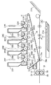
図3は、電子写真方式のカラー画像形成装置の一例である中間転写体28を採用したタンデム方式のカラー画像形成装置の断面図である。図3を用いて、電子写真方式のカラー画像形成装置における画像形成部202の動作を説明する。画像形成部202は、画像処理部201より出力される露光時間に応じて露光光を駆動し静電潜像を形成し、この静電潜像を現像して単色トナー像を形成する。そして、この単色トナー像を重ね合わせて多色トナー像を形成し、この多色トナー像を記録媒体11へ転写したのちにその記録媒体上の多色トナー像を定着させる。帯電ユニットは、イエロー(Y)、マゼンダ(M)、シアン(C)、ブラック(K)のステーション毎に感光体22Y、22M、22C、22K を帯電させるための4個の注入帯電器 23Y、23M、23C、23Kを備える。各注入帯電器にはスリーブ23YS、23MS、23CS、23KSが設けられている。
(Description of image forming unit)
FIG. 3 is a cross-sectional view of a tandem color image forming apparatus that employs an
感光体 22Y、22M、22C、22K は、アルミシリンダの外周に有機光導伝層を塗布して構成し、図示しない駆動モータの駆動力が伝達されて回転可能である。駆動モータは感光体22Y、22M、22C、22Kを画像形成動作に応じて反時計周り方向に回転させることが可能である。
The
露光ユニットは、感光体22Y、22M、22C、22Kへスキャナ部24Y、24M、24C、24Kより露光光を照射し、感光体の表面を選択的に露光することにより、静電潜像を形成するように構成されている。
The exposure unit irradiates the
現像ユニットは、静電潜像を可視化するために、ステーション毎にイエロー(Y)、マゼンダ(M)、シアン(C)、ブラック(K)の現像を行う4個の現像器26Y、26M、26C、26Kを備える構成である。そして、各現像器には、スリーブ26YS、26MS、26CS、26KSが設けられている。尚、各々の現像器26Y、26M、26C、26Kは脱着が可能である。
The developing unit has four developing
転写ユニットは、感光体22から中間転写体28へ単色トナー像を転写するために、中間転写体28を時計周り方向に回転させる。そして、感光体 22Y、22M、22C、22Kとその対向に位置する一次転写ローラ27Y、27M、27C、27Kの回転に伴って、単色トナー像を転写する。
The transfer unit rotates the
一次転写ローラ27に適当なバイアス電圧を印加すると共に感光体22の回転速度と中間転写体28の回転速度に差をつけることにより、効率良く単色トナー像を中間転写体28上に転写する(これを一次転写という。)。
By applying an appropriate bias voltage to the primary transfer roller 27 and making a difference between the rotation speed of the
更に転写ユニットは、ステーション毎に単色トナー像を中間転写体28上に重ね合わせ、重ね合わせた多色トナー像を中間転写体28の回転に伴い、二次転写ローラ29まで搬送する。更に記録媒体11を給紙トレイ21(a,b)から二次転写ローラ29へ狭持搬送し、記録媒体11に中間転写体28上の多色トナー像を転写する。この二次転写ローラ29に適当なバイアス電圧を印加して、静電的にトナー像を転写する(これを二次転写という。)。二次転写ローラ29は、記録媒体11上に多色トナー像を転写している間、29aの位置で記録媒体11に当接し、処理後は29bの位置に離間する。
Further, the transfer unit superimposes the single color toner image on the
定着ユニットは、記録媒体11に転写された多色トナー像を記録媒体11に溶融定着させるために、記録媒体11を加熱する定着ローラ32と記録媒体11を定着ローラ32に圧接させるための加圧ローラ33を備えている。定着ローラ32と加圧ローラ33は中空状に形成され、内部にそれぞれヒータ34、35が内蔵されている。定着装置31は、多色トナー像を保持した記録媒体11を定着ローラ32とか圧ローラ33により搬送するとともに、熱および圧力を加え、トナーを記録媒体11に定着させる。
The fixing unit presses the
トナー定着後の記録媒体11は、その後図示しない排出ローラによって図示しない排紙トレイに排出して画像形成動作を終了する。
The
クリーニングユニット30は、中間転写体28上に残ったトナーをクリーニングするものであり、中間転写体28上に形成された4色の多色トナー像を記録媒体11に転写した後に残った廃トナーは、クリーナ容器に蓄えられる。
The
色ずれ検知センサ41は、中間転写体28へ対向する位置に配置されている。中間転写体28上に色ずれ検知用パッチを形成し、パッチの検知タイミングから各色の色ずれの量を判定することが可能である。
The color
図4は色ずれ検知の一例を示す図である。中間転写体28の上方において、走査方向に4個の色ずれ検知センサ41a、41b、41c、41dが設けられている。中間転写体28が搬送方向に移動して、中間転写体28上に形成されたCMYK各色の色ずれ検知用パッチ402が各センサの下方を通過する。各検知用センサ41は、下方を通過する各検知用パッチ402を検知することが可能な構成になっている。
FIG. 4 is a diagram illustrating an example of color misregistration detection. Above the
図4に示すように、検知用センサ41が走査方向の左、中央1、中央2、右の4箇所で色ずれを検知することにより、不図示のCPUの制御の下、走査線の傾き及び湾曲の大きさを求めることができる。装置の構成によっては、左右2箇所のみに色ずれ検知センサ41を備えるカラー画像形成装置も有り、その場合は傾きの大きさのみを求めることが可能である。
As shown in FIG. 4, the
図5は主走査線における色ずれの補正を説明する図である。図中501は理想的な走査線を示し、感光体22の回転方向に対して垂直に走査がおこなわれる。図中502は感光体22の位置精度や径のずれ、および各色のスキャナ部24における光学系の位置精度に起因する、傾きおよび湾曲が発生した実際の走査線である。
FIG. 5 is a diagram for explaining correction of color misregistration in the main scanning line. In the figure,
このような走査線の傾きおよび湾曲の大きさがC、M、Y、K の画像ステーション毎に異なるため、中間転写体28上に全色のトナー像を転写した画像において色ずれが発生する。主走査方向(x方向)はレーザスキャン方向に対応し、副走査方向(y方向)は、記録媒体の搬送方向に対応する。
Since the inclination and curvature of the scanning line are different for each of C, M, Y, and K image stations, color misregistration occurs in an image in which all color toner images are transferred onto the
画像形成領域の走査開始位置となるポイントAを基準点(Pa)とする。理想的な走査線501と実際の走査線502との副走査方向(y方向)のずれ量(m1、m2、m3)を主走査方向に分割した複数のポイント(B、C、D)で測定し、対応する走査線502上の点をPb、Pc、Pdとする。
Point A that is the scanning start position of the image forming area is defined as a reference point (Pa). Measured at a plurality of points (B, C, D) obtained by dividing the amount of deviation (m1, m2, m3) between the
主走査方向(X方向)を領域1(ポイントPa−Pb間)、領域2(Pb−Pc間)、領域3(Pc−Pd間)に分割し、各ポイント間を結ぶ直線をLab、Lbc、Lcdとする。領域1における副走査方向(y方向)のずれ量の増分はm1、領域2におけるずれ量の増分はm2−m1、そして、領域3におけるずれ量の増分はm3−m2となる。そして、各領域の領域長がそれぞれL1、L2、L3である場合、各領域の増分と領域長とにより、直線Lab、Lbc、Lcdの傾きを求めることができる。
The main scanning direction (X direction) is divided into region 1 (between points Pa and Pb), region 2 (between Pb and Pc), and region 3 (between Pc and Pd), and straight lines connecting the points are labeled Lab, Lbc, Let it be Lcd. The increment of the shift amount in the sub-scanning direction (y direction) in the
ずれ量の増分が正の値である場合、対応する領域における走査線は右上がりの傾き(+)を示し、ずれ量の増分が負の値である場合、対応する領域における走査線は右下がりの傾き(‐)を示す。 When the deviation amount increment is a positive value, the scanning line in the corresponding region shows a slope that rises to the right (+). When the deviation amount increment is a negative value, the scanning line in the corresponding region falls to the right. The slope of (-) is shown.
(画像処理部201の説明)
次に、図2のカラー画像形成装置における画像処理部201の処理について説明する。
(Description of the image processing unit 201)
Next, processing of the
図2において、画像生成部204は、不図示のコンピュータ装置等から受信する印刷データより、印刷処理が可能なビットマップ画像データを生成する。ここで印刷データは、PDL(Page Description Language)と呼ばれるページ画像データを作成するためのプリンタ記述言語が一般的であり、通常、文字やグラフィックス、イメージ等のデータの描画命令が含まれている。このような印刷データを解析しラスタライズ処理することでビットマップ画像データ生成する。
In FIG. 2, an
画像生成部204で生成されるビットマップ画像データがRGB色空間画像データであり、画像形成部202への入力がYMCKの4色の色剤に対応する画像データである場合、色変換部205は色変換処理を実行する。すなわち、色変換部205は、RGB色空間画像データをルックアップテーブル等の参照によりCMYK色空間画像データに変換する変換処理を実行する。
When the bitmap image data generated by the
ハーフトーン処理部206は、スクリーン情報207より取得した所定のスクリーンパターンを用いて入力される画素データの階調数を削減する処理を実行する。通常、画像形成部202には2、4、16階調など、低階調データのみ入力可能であることが多い。従って、少ない階調数しか再現できない画像形成部202においても安定した中間調表現を可能とするようにハーフトーン処理部206による階調数の削減処理を行う。ハーフトーン処理部206は、画素単位の階調表現から面積単位での階調表現に変換する擬似中間調処理を行い、ビットマップメモリ208に色毎に処理後のビットマップ画像データを蓄積する。ビットマップメモリ208は、印刷処理を行うラスタイメージデータを一旦格納するものであり、1ページ分のイメージデータを格納するページメモリ、または、複数ライン分のデータを記憶するバンドメモリにより構成することが可能である。
The
画像生成部204においてビットマップ画像データが生成される際に、同時に各画素がどのような画像特性に属するのかを示す属性情報が生成される。ここで属性情報とは、それぞれの画像特性に応じたデータの種類を特定するための情報をいう。
When bitmap image data is generated in the
例えば、文字データ若しくはその画像特性を持ったデータからなるテキスト属性、ビットマップデータ若しくはその画像特性を持ったデータからなるイメージ属性が挙げられる。また、ドローデータもしくはその画像特性を持ったデータからなるグラフィック属性といった属性情報が挙げられる。ビットマップ画像の各画素に対し属性情報を付加することで、それぞれの属性の画像特性に適した画像処理が実行可能となる。 For example, there are a text attribute made up of character data or data having image characteristics, and an image attribute made up of bitmap data or data having image characteristics. Also, attribute information such as graphic attributes made up of draw data or data having image characteristics thereof can be mentioned. By adding attribute information to each pixel of the bitmap image, image processing suitable for the image characteristics of each attribute can be executed.
イメージ属性とテキスト属性に対し、RGB色空間画像データからCMYK色空間画像データへの色変換処理を行う際、色変換部205は利用するルックアップテーブルを切り替えが可能である。
When performing color conversion processing from RGB color space image data to CMYK color space image data for the image attribute and text attribute, the
また、ハーフトーン処理部206は、属性ごとに異なったスクリーン情報207を用いてハーフトーン処理を施すことが可能である。この場合、ハーフトーン処理部206は、イメージ属性である自然画像に対しては階調性を優先する低線数スクリーンを適用することができる。また、ハーフトーン処理部206は、テキスト属性である文字、グラフィック属性であるラインには解像度を優先する高線数スクリーンを適用することができる。
The
色ずれ補正部209は、スクリーン情報207及び色ずれ補正量演算部213の演算結果に基づいて、走査線の傾き及び湾曲による色ずれを補正する。色ずれ補正部209における処理の詳細は後述する。
The color
その後、色ずれを補正したビットマップ画像は、パルス幅変調(PWM: Pulse Width Modulation)部210において、画像形成部202におけるスキャナ部24へ入力可能な露光時間へ変換される。
Thereafter, the bitmap image corrected for color misregistration is converted into an exposure time that can be input to the
(色ずれの補正方法)
次に本実施形態における色ずれの補正方法の詳細を説明する。
(Color misregistration correction method)
Next, details of the color misregistration correction method in the present embodiment will be described.
図2において、211は画像形成部202に搭載された色ずれ量記憶部であり、色毎に上述した領域(図5の領域1、領域2、領域3)ごとの色ずれプロファイル情報212C、212M、212Y、212Kを格納する。
In FIG. 2,
複数のポイント(B、C、D)で測定した実際の主走査線502と、理想的な主走査線501との副走査方向のずれ量が色ずれプロファイル情報となる。図6は、色ずれ量記憶部211に記憶されるプロファイル情報の一例を示す図である。尚、プロファイルの形式はこれに限ることはなく、走査線の傾きおよび湾曲の特性が分かるものであれば良い。
The amount of deviation in the sub-scanning direction between the actual
色ずれ量記憶部211に記憶される色ずれプロファイル情報212の取得方法は、いくつかの方法が考えられる。例えば、前述した色ずれ検知センサ41a,41b,41c,41dを用いて、中間転写体28上に形成した色ずれ用検知パッチ402の検出結果から、傾きを求めることが可能である。また、画像形成装置の製造工程において、上記ずれ量を測定し取得する方法もある。あるいは予め用意された色ずれ測定用チャートを画像形成装置で出力し、イメージスキャナなどで出力画像を電子情報化し、その電子化された情報からプロファイル情報を取得する方法等でもプロファイル情報の取得は可能である。
There are several methods for obtaining the color misregistration profile information 212 stored in the color misregistration
図2の色ずれ補正量演算部213は、色ずれ量記憶部211に記憶された色ずれプロファイル情報212及びエンジンプロファイル情報214に基づき、色ずれを相殺する補正量を算出して、色ずれ補正部209へ出力する。
The color misregistration correction
色ずれ補正部209による演算の具体的な内容を以下に示す。
Specific contents of the calculation by the color
主走査方向の座標データをx(dot)、副走査方向の色ずれ補正量をΔy(dot)とした場合、図5における各領域1、2、3における色ずれ補正量Δyは以下の演算式により求めることができる(画像形成解像度をr(dpi)とする)。ここで、式中「*」は乗算を示すものとする。
When the coordinate data in the main scanning direction is x (dot) and the color misregistration correction amount in the sub scanning direction is Δy (dot), the color misregistration correction amount Δy in each of the
領域1: Δy1 =x*(m1/L1) ・・・(1)
領域2: Δy2 = m1/r+(x-(L1/r))*((m2-m1)/(L2-L1)) ・・・(2)
領域3: Δy3 = m2/r+(x-(L2/r))*((m3-m2)/(L3-L2)) ・・・(3)
L1、L2、L3は領域1、領域2、領域3の領域長さ(単位mm)を示し、m1、m2、m3は各領域1、領域2、領域3の右端の点(Pb、Pc、Pd)における理想的な走査線501と、実際の走査線502とのずれ量である。
Region 1: Δy1 = x * (m1 / L1) (1)
Region 2: Δy2 = m1 / r + (x- (L1 / r)) * ((m2-m1) / (L2-L1)) (2)
Region 3: Δy3 = m2 / r + (x- (L2 / r)) * ((m3-m2) / (L3-L2)) (3)
L1, L2, and L3 indicate the region length (unit: mm) of
ここで、エンジンプロファイル情報214は、用紙サイズに対応した基準点からのオフセット量情報、各色のビームの走査方向情報、記録媒体搬送速度により構成される。
Here, the
例えば、走査方向が異なる場合には、走査方向に応じて補正量に符号をつける必要がある。例えば、エンジンプロファイル情報214において、走査方向がForward時の符号は負、Reverse時の符号は正として、色ずれ補正量演算部213は補正量を算出する。
For example, when the scanning direction is different, it is necessary to add a sign to the correction amount according to the scanning direction. For example, in the
また、記録媒体搬送速度(印刷速度)が異なる場合、色ずれ補正量演算部213は、印刷速度に応じて補正量を制御することが可能である。例えば、画像形成スピードが通常の1/2倍速の場合、走査スピードは変えず、走査動作2回のうち1回分の走査で画像出力を行い、残り1回分では画像出力を行わないように、補正量を1倍速の時の1/2にすることが可能である。
When the recording medium conveyance speed (printing speed) is different, the color misregistration correction
色ずれ補正量演算部213が算出した各画素の補正量に基づき、色ずれ補正部209は、ビットマップデータの補正を行う。
Based on the correction amount of each pixel calculated by the color misregistration correction
(色ずれ補正部209の構成)
図7は本実施形態にかかる色ずれ補正部209の構成を示すブロック図である。色ずれ補正は色毎(CMYK)にそれぞれの色ずれ補正部209C、209M、209Y、209Kで処理される。尚、説明の重複を避けるため、シアン(C)に関する色ずれ補正部(C)209Cを例として色ずれ補正部の内容を説明するが、他の色ずれ補正部209M、209Y、209Kについても同様の構成及び処理を実行するものとする。
(Configuration of the color misregistration correction unit 209)
FIG. 7 is a block diagram showing the configuration of the color
色ずれ補正部(C)209Cは、座標変換部701、ラインバッファ702、平滑化判定部703、階調値変換部704により構成される。ラインバッファ702は、ビットマップメモリ208から色ずれ補正処理前の情報を格納するライン単位のメモリであり、補正量分の情報をライン単位で格納することが可能である。
The color misregistration correction unit (C) 209C includes a coordinate
座標変換部701は、主走査方向および副走査方向の座標位置データと、色ずれ補正量演算部213より得られる補正量Δyに基づき、出力画像データの再構成を行う。具体的には、座標変換部701は、補正量Δyの整数部分の補正処理、つまり1画素単位での色ずれ補正を行い、出力画像データの再構成を行う。
The coordinate
(座標変換部701における補正処理)
ここで、座標変換部701における補正処理の内容を図8の参照により説明する。座標変換部701は、図8(a)に示す直線近似された走査線の色ずれ量から求められる色ずれ補正量Δyの整数部分の値に応じてビットマップメモリ208に格納された画像データの副走査方向の座標をオフセットする。
(Correction process in coordinate conversion unit 701)
Here, the content of the correction processing in the coordinate
例えば図8(b)に示すように、副走査方向の座標位置がnライン目のデータを再構成する場合、主走査方向の部分領域[1]では色ずれ補正量Δyは0以上1画素未満である。座標変換部701はビットマップメモリ208からnライン目のデータを読み出す。
For example, as shown in FIG. 8B, when the coordinate position in the sub-scanning direction reconstructs data of the nth line, the color misregistration correction amount Δy is 0 or more and less than one pixel in the partial region [1] in the main scanning direction. It is. The coordinate
次に、主走査方向の部分領域[2]では色ずれ補正量Δyが1画素以上2画素未満であり、1ライン分オフセットした位置のビットマップ画像、つまりビットマップメモリ208からn+1ライン目のデータを読み出すように座標変換処理を行う。同様に部分領域[3]ではn+2ライン目、部分領域[4]ではn+3ライン目のデータを読み出すように座標変換処理を行う。
Next, in the partial region [2] in the main scanning direction, the color misregistration correction amount Δy is 1 pixel or more and less than 2 pixels, and a bitmap image at a position offset by one line, that is, data of the (n + 1) th line from the
図8(c)は、座標変換部701により画素単位での色ずれ補正をおこなった画像データを像担持体に露光した露光イメージを例示する図である。各部分領域[1]〜[5]における露光イメージは、各部分領域において発生した色ずれ補正量に対応して露光位置がオフセットされている。
FIG. 8C is a diagram exemplifying an exposure image obtained by exposing the image carrier with image data that has been subjected to color shift correction in pixel units by the coordinate
(階調値変換部704における1画素未満の補正処理)
次に、図9の参照により、階調値変換部704における1画素未満の補正処理、すなわち、色ずれ補正量Δyの小数点以下のずれ量の補正処理を説明する。小数点以下のずれ量の補正は、注目画素に対して副走査方向に位置する前後の画素の階調値を調整することにより行う。
(Correction processing of less than one pixel in the gradation value conversion unit 704)
Next, correction processing for less than one pixel in the gradation
図9(a)は、右上がりの傾きを有する走査線を例示する図である。図9(b)は階調値変換前の水平な直線のビットマップイメージを示す図であり、図9(c)は図9(a)の走査線の傾きによる色ずれを相殺するための補正イメージで、図9(b)のビットマップイメージに対応する補正イメージを示す図である。 FIG. 9A is a diagram illustrating a scanning line having an upward slope. FIG. 9B is a diagram showing a bitmap image of a horizontal straight line before gradation value conversion, and FIG. 9C is a correction for canceling the color shift due to the inclination of the scanning line in FIG. It is a figure which shows the correction image corresponding to the bitmap image of FIG.9 (b) by an image.
図9(c)の補正イメージを実現するために、階調値変換部704は、注目画素に対して、副走査方向に位置する前後の画素の階調値調整を行う。図9(d)は色ずれ補正量Δyと階調値変換をおこなうための補正係数の関係を例示した階調値変換テーブルである。パラメータkは色ずれ補正量Δyの整数部分(小数点以下を切り捨て)を示し、1画素単位での副走査方向の補正量を表す。パラメータβとパラメータα((4)、(5)式)は、1画素未満の副走査方向の補正を行うための補正係数で、色ずれ補正量Δyの小数点以下の情報により、副走査方向における前後の画素の階調値の分配率を示すパラメータである。
In order to realize the correction image in FIG. 9C, the gradation
β=Δy―k ・・・(4)
α=1−β ・・・(5)
αは注目画素に対する先行画素の分配率
βは注目画素に対する後行画素の分配率
図9(e)は、図9(d)の階調値変換テーブルの係数に従って、副走査方向に位置する前後の画素の階調値比率を調整するための階調値変換を行ったビットマップ画像を例示する図である。図9(f)は、階調値変換されたビットマップ画像の像担持体での露光イメージであり、この露光イメージに基づいて形成される直線画像は、主走査ラインの傾きが相殺され、水平な直線画像が形成されることになる。
β = Δy−k (4)
α = 1−β (5)
α is the distribution ratio of the preceding pixel with respect to the pixel of interest β is the distribution ratio of the succeeding pixel with respect to the pixel of interest FIG. 9 (e) is before and after being positioned in the sub-scanning direction according to the coefficients of the gradation value conversion table of FIG. It is a figure which illustrates the bitmap image which performed the gradation value conversion for adjusting the gradation value ratio of the pixel of this. FIG. 9F shows an exposure image of a bitmap image that has been subjected to gradation value conversion on an image carrier. A straight line image formed based on this exposure image cancels the inclination of the main scanning line and is horizontal. A straight line image is formed.
一方、細密画像等のパターンの画像に対しては1画素未満の補正を行わない方が画像品質の観点において良い。その場合、階調値変換部704における補正処理は、図10(a)に示すように、階調値変換テーブルに関して副走査方向における前後の画素の階調値の分配率を一律にパラメータβ=0、α=1とすればよい。このパラメータの設定により、1画素未満の色ずれ補正は、色ずれ補正量演算部213の演算結果によらず無効化される。図10(b)は、色ずれ補正量Δyの整数部分のデータに基づいて、1画素単位で副走査方向に座標変換を行ったビットマップ画像を示す図であり、図10(c)は、ビットマップ画像の像担持体での露光イメージである。この露光イメージに基づいて形成される画像は、主走査ラインの傾きが相殺され、水平な直線画像が形成されることになる。
On the other hand, it is better in terms of image quality that correction of less than one pixel is not performed on a pattern image such as a fine image. In this case, as shown in FIG. 10A, the correction processing in the gradation
ここで、1画素未満の色ずれ補正を行う画像と、行わない画像との判定は、平滑化判定部703が行う。平滑化判定部703における判定方法は後述する。平滑化判定部703の判定結果に基づき、図示しない階調値変換テーブル選択部は使用する階調値変換テーブルを選択する。階調値変換部704は、選択された階調値変換テーブルに基づいて、補正処理を行う。
Here, the smoothing
(平滑化判定部704における判定)
次に、平滑化判定部704における判定方法を具体的に説明する。電子写真方式の画像形成装置におけるハーフトーン処理の際、用いられるスクリーンの種類は、大別すると線成長するラインスクリーンと点成長するドットスクリーンの2種類に分けることができる。
(Determination in smoothing judgment unit 704)
Next, the determination method in the smoothing
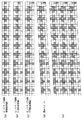
図11はスクリーンを適用したビットマップ画像を例示する図である。図11(a)は、ラインスクリーンを適用した画像であり、図11(b)はドットスクリーンを適用したものである。 FIG. 11 is a diagram illustrating a bitmap image to which a screen is applied. FIG. 11A shows an image to which a line screen is applied, and FIG. 11B shows an image to which a dot screen is applied.
次に、これらスクリーンを適用した画像(図11(a),(b))に対する色ずれ補正を図12、図13の参照により説明する。 Next, color misregistration correction for images (FIGS. 11A and 11B) to which these screens are applied will be described with reference to FIGS.
図12はラインスクリーンを適用した画像に対する1画素未満の補正を説明する図であり、図13はドットスクリーンを適用した画像に対する1画素未満の色ずれ補正を説明する図である。 FIG. 12 is a diagram illustrating correction of less than one pixel for an image to which a line screen is applied, and FIG. 13 is a diagram illustrating correction of color misregistration of less than one pixel for an image to which a dot screen is applied.
図12(a)はラインスクリーンを適用した後のビットマップ画像であり、この状態でハーフトーン処理された画像はビットマップメモリ208に格納されている。図12(b)は座標変換部701により、座標変換された後のビットマップ画像であり、図12(c)は図12(b)に関して階調値補正部704により、1画素未満の補正処理を適用したビットマップ画像を示す図である。図12(d)は図12(c)に関する像担持体での露光イメージを示す図である。
FIG. 12A shows a bitmap image after the line screen is applied, and the image subjected to the halftone process in this state is stored in the
また、図12(e)はハーフトーン処理された後、色ずれ補正処理をした露光イメージを示す図であるが、1画素未満の補正処理のため、濃度ムラが発生し、その結果、モアレが発生することがわかる。 FIG. 12E is a diagram showing an exposure image that has been subjected to color misregistration correction processing after being subjected to halftone processing, but due to correction processing of less than one pixel, density unevenness occurs, resulting in moire. It can be seen that it occurs.
一方、図13(a)はドットスクリーンを適用した後のビットマップ画像である。図13(b)は座標変換部701により、座標変換された後のビットマップ画像であり、図13(c)は図13(b)に関して階調値補正部704により、1画素未満の補正処理を適用したビットマップ画像を示す図である。図13(d)は図13(c)に関する像担持体での露光イメージを示す図である。
On the other hand, FIG. 13A shows a bitmap image after applying the dot screen. FIG. 13B is a bitmap image after coordinate conversion by the coordinate
図13(e)はハーフトーン処理された後、色ずれ補正処理をした露光イメージを示す図であるが、ラインスクリーンを適用した補正(図12(e))と異なり、1画素未満の補正処理による弊害がほとんど生じていないことが分かる。 FIG. 13E is a diagram showing an exposure image that has been subjected to color misregistration correction processing after halftone processing. Unlike the correction using a line screen (FIG. 12E), correction processing for less than one pixel is performed. It can be seen that there is almost no adverse effect caused by.
従って、中間濃度画像に関して、画像品質の観点から平滑化処理を行うか否かの判定には、適用されたスクリーンの種類より判定が可能であることがわかる。尚、画像に適用されるスクリーンの種類は、その画像領域の属性情報に依存することが多い。すなわち属性情報を用いて、イメージ属性である画像に対しては階調性を優先する低線数ラインスクリーンを適用し、テキスト属性である文字には解像度を優先する高線数ドットスクリーンを適用することが好ましいものとなる。 Therefore, it can be seen that the determination as to whether or not to perform the smoothing process on the intermediate density image from the viewpoint of image quality can be made based on the type of screen applied. Note that the type of screen applied to an image often depends on the attribute information of the image area. That is, using the attribute information, a low line number line screen that prioritizes gradation is applied to an image that is an image attribute, and a high line number dot screen that prioritizes resolution is applied to a character that is a text attribute. Is preferable.
本実施形態では、画像生成部204でビットマップ画像と同時に生成された属性情報を基に、ハーフトーン処理部207は、ハーフトーン処理時に適用するスクリーンを切り分ける(選択する)。
In the present embodiment, based on the attribute information generated at the same time as the bitmap image by the
色ずれ補正部209はその領域におけるハーフトーン処理時に適用されたスクリーン情報207を取得する。そして、このスクリーン情報を基に平滑化判定部704は、1画素未満の補正処理、すなわち平滑化処理を行うか否かを判定する。具体的にはラインスクリーンが適用された画像領域には平滑化処理を行わないと判定する。
The color
一方、ドットスクリーンが適用された画像領域に対して、平滑化判定部704は、1画素未満の補正処理(平滑化補正処理)を行うと判定する。
On the other hand, the smoothing
尚、画像領域の濃度がある程度高い場合には、ハーフトーン処理後の画像データに平滑化処理を適用しても濃度ムラの影響がほとんどないため、一律に補正処理を行うものとする。 When the density of the image area is high to some extent, even if the smoothing process is applied to the image data after the halftone process, there is almost no influence of density unevenness, and therefore the correction process is performed uniformly.
図14は、画像の属性情報とその際に適用されるスクリーンとの関係を示すスクリーン情報207の内容を例示する図である。図14において、画像は3種類の画像属性(1401〜1403)を含んでいるものとする。各画像属性には、CMYKの色毎に、スクリーン線数(1404C、M、Y、K)、スクリーン角度(1405C、M、Y、K)、スクリーンの種類(1406C、M、Y、K)が設定されている。
FIG. 14 is a diagram illustrating the contents of
例えば、画像属性1のシアン(C)には、スクリーンの種類(1406C)としてラインスクリーンが設定されており、スクリーン線数は190lpi(line per inch)、スクリーン角度は108°である。
For example, a line screen is set as the screen type (1406C) in cyan (C) of
上述の説明において、1画素未満の色ずれ補正を実行するか否かの判定は、スクリーンの種類(ラインスクリーン、またはドットスクリーン)に基づくものである。しかしながら、本発明の趣旨はこれに限定されるものでなく、スクリーン線数やスクリーン角度に関する情報を用いることも可能である。 In the above description, the determination as to whether or not to perform color misregistration correction for less than one pixel is based on the type of screen (line screen or dot screen). However, the gist of the present invention is not limited to this, and information on the number of screen lines and the screen angle can also be used.
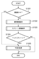
図15は、不図示のCPU、ハーフトーン処理部207、色ずれ補正部209の制御の基に実行される平滑化判定処理の流れを説明するフローチャートである。まず、ステップS1501において、平滑化処理を行うか判定する画素の濃度値がある予め決められた閾値(th)より大きい場合(S1501−Yes)、その後の判定処理を行わず平滑化処理を行うと判定をする。
FIG. 15 is a flowchart for explaining the flow of a smoothing determination process executed under the control of a CPU, a
一方、濃度が閾値(th)以下の場合(S1501−No)、処理をステップS1502に進め、ハーフトーン処理部207はその画素についての属性情報を選択し、取得する。
On the other hand, if the density is equal to or lower than the threshold (th) (S1501-No), the process proceeds to step S1502, and the
そして、ステップS1503において、色ずれ補正部209は属性情報を基に選択されたスクリーン情報を取得する。ここで取得されたスクリーン情報がドットスクリーンの場合(S1504−Yes)、ドットスクリーンが適用された画像領域(画素)に対して、平滑化判定部704は、1画素未満の補正処理を行うと判定する(S1505)。
In step S1503, the color
一方、ステップS1504の判定で、平滑化判定部704は、スクリーン情報がラインスクリーンの場合(S1504−No)、ラインスクリーンの適用された画像領域(画素)には平滑化処理を行わないと判定し、処理を終了する
本実施形態に拠れば、ハーフトーン処理時に使用するスクリーンの種類に応じて、1画素未満の補正を行う画像と行わない画像とを判定することで、色ずれ補正時の濃度ムラを回避することが可能になる。
On the other hand, in the determination in step S1504, when the screen information is a line screen (S1504-No), the smoothing
これにより、処理の対象となる画素ごとにパターンマッチング等を行うこと無しに、より簡易に色ずれ補正時の濃度ムラを回避することが可能になる。 This makes it possible to more easily avoid density unevenness during color misregistration correction without performing pattern matching or the like for each pixel to be processed.
あるいは、ハーフトーン処理時に使用するスクリーンの種類に応じて、1画素未満の補正を行う画像と行わない画像とを判定することで、大幅なコストアップをすることなく、形成する画像の品質を向上させることが可能になる。 Or, depending on the type of screen used during halftone processing, it is possible to improve the quality of the image to be formed without significantly increasing the cost by determining whether the image is corrected with less than one pixel or not. It becomes possible to make it.
(第2実施形態)
第1実施形態では、スクリーンの種類によって1画素未満の補正処理を実行するか否かを判定したが、1画素未満の補正処理による濃度ムラの影響は、スクリーンの角度、及び色ずれ量によっても異なるものとなる。第1実施形態における1画素未満の色ずれ補正は、副走査方向に位置する前後の画素へ階調値の分配をすることで行われるため、補正後のスクリーンの角度が水平に近いほど平滑化処理による影響が大きくなる。一方、補正後のスクリーンの角度が垂直に近ければ平滑化処理の影響をほとんど受けないことになる。そこで、本実施形態では、ハーフトーン処理に際に使用されるスクリーンの角度、及び色ずれ補正時の補正量を基に平滑化判定を行う方法を説明する。
(Second Embodiment)
In the first embodiment, it is determined whether or not the correction process of less than one pixel is executed depending on the type of the screen. However, the influence of density unevenness due to the correction process of less than one pixel also depends on the screen angle and the amount of color misregistration. It will be different. The color misregistration correction of less than one pixel in the first embodiment is performed by distributing the gradation value to the previous and subsequent pixels located in the sub-scanning direction, and therefore smoothing is performed as the corrected screen angle is closer to the horizontal. The effect of processing increases. On the other hand, if the corrected screen angle is close to vertical, the screen is hardly affected by the smoothing process. Therefore, in the present embodiment, a method for performing smoothing determination based on the screen angle used in the halftone process and the correction amount at the time of color misregistration correction will be described.
走査線の傾き及び湾曲による色ずれ量は、色ずれ量記憶部211に格納されている色ずれプロファイル情報212C、212M、212Y、212K(図6を参照)より取得することが可能である。補正後のビットマップ画像は、傾き量に基づき近似される各色の色ずれ量を相殺するように補正される。
The color misregistration amount due to the inclination and curvature of the scanning line can be acquired from the color
ここで、もとのハーフトーン処理で使用されたスクリーン角度をA°として、図6に示すイエロー(Y)の領域1に関して色ずれ補正がなされた場合、補正後のビットマップ画像のスクリーン角度B°は、(6)、(7)式により与えられる。
Here, assuming that the screen angle used in the original halftone processing is A °, when color misregistration correction is performed for the yellow (Y)
B°=A°−Δr° ・・・(6)
Δr°=tan-1(m1/L1)・・・(7)
ここで、平滑化判定部703は、(6)式の演算においてスクリーン角度A°を図14で示したスクリーン情報207(スクリーン角度1405Y)の参照により取得することが可能である。平滑化判定部703は、(6)式により算出されるB°を基に1画素未満の補正処理を行うか否か判定する。
B ° = A ° −Δr ° (6)
Δr ° = tan-1 (m1 / L1) (7)
Here, the
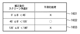
図16は、補正後のスクリーン角度B°に対して平滑化処理を行うか否かの判定結果を示す図である。補正後のスクリーン角度B°が水平に近い、0°≦B°<45°及び135°≦B°<180°の場合、平滑化判定部703は1画素未満の補正処理を行わない(図中「×」印)と判定する(1601、1603)。一方、平滑化判定部703は、補正後のスクリーン角度B°が垂直に近い、45°≦B°<135°では1画素未満の補正処理を行う(図中「○」印)と判定する(1602)。
FIG. 16 is a diagram illustrating a determination result of whether or not to perform the smoothing process on the corrected screen angle B °. When the corrected screen angle B ° is nearly horizontal, 0 ° ≦ B ° <45 ° and 135 ° ≦ B ° <180 °, the smoothing
本実施形態に拠れば、ハーフトーン処理時におけるスクリーン角度及び色ずれ量の情報を基に1画素未満の補正を行う画像と補正を行わない画像とを判定することで、色ずれ補正時の濃度ムラの回避が可能になる。 According to the present embodiment, the density at the time of color misregistration correction is determined by determining an image to be corrected by less than one pixel and an image to be uncorrected based on information on the screen angle and color misregistration amount at the time of halftone processing. Unevenness can be avoided.
これにより、処理の対象となる画素ごとにパターンマッチング等を行うこと無しに、より簡易に色ずれ補正時の濃度ムラを回避することが可能になる。 This makes it possible to more easily avoid density unevenness during color misregistration correction without performing pattern matching or the like for each pixel to be processed.
あるいは、スクリーン角度及び色ずれ量の情報を基に、1画素未満の補正を行う画像と行わない画像とを判定することで、大幅なコストアップを図ることなく、形成する画像の品質を向上させることが可能になる。 Alternatively, it is possible to improve the quality of an image to be formed without significantly increasing the cost by determining an image to be corrected with less than one pixel and an image not to be performed based on information on a screen angle and a color misregistration amount. It becomes possible.
(第3実施形態)
前述のように、電子写真方式の画像形成装置は画像階調値と実際の画像濃度値との比例関係を保った上で孤立画素を形成することが不得意であり、これに起因して1画素未満の補正処理の影響が特に細線領域で濃度ムラとして現れていた。これは副走査方向の前後の画素へ階調値を分配することにより、最大の露光光で露光されるドットを複数のハーフドットで再構成する結果、ハーフドットの安定性がフルドットより悪いために現れる現象である。一方、補正前のドットが初めからハーフドットの場合、副走査方向の前後の画素へ階調値の分配することで、より画像形成におけるドット間の安定度が低下することになる。
(Third embodiment)
As described above, an electrophotographic image forming apparatus is not good at forming an isolated pixel while maintaining a proportional relationship between an image gradation value and an actual image density value. The influence of the correction processing for less than pixels appears as density unevenness particularly in the thin line region. This is because the half-dot stability is worse than the full-dot as a result of reconfiguring the dots exposed with the maximum exposure light by multiple half-dots by distributing the gradation values to the pixels before and after in the sub-scanning direction. It is a phenomenon that appears in On the other hand, when the dot before correction is a half dot from the beginning, by distributing the gradation value to the pixels before and after in the sub-scanning direction, the stability between dots in image formation is further reduced.
本実施形態では、ハーフトーン処理の際に使用されるスクリーンの出力階調により、1画素未満の補正処理を行うか否かを判定する処理を説明する。 In the present embodiment, a process for determining whether or not to perform correction processing for less than one pixel according to the output gradation of the screen used in halftone processing will be described.
ハーフトーン処理を行う際、使用するスクリーンの種類により、ハーフトーン処理後のビットマップ画像の階調数は異なるものとなる。平滑化判定部703は、ハーフトーン後の階調数をハーフトーン処理に使用するスクリーンの種類(ラインスクリーンまたはドットスクリーン)により判定することが可能である。すなわち、平滑化判定部703は、スクリーン情報207を取得し、スクリーン出力の階調数が多階調(4階調や16階調等)である場合には、1画素未満の補正処理、すなわち平滑化処理を行わないものと判定する。一方、スクリーン出力の階調数が2階調である場合、平滑化判定部703は平滑化処理を行うものと判定する。
When halftone processing is performed, the number of gradations of the bitmap image after halftone processing differs depending on the type of screen used. The smoothing
ハーフトーン後のビットマップ画像が多階調である場合、1画素単位の補正により生じるオフセットさせた境界における不自然な段差は、2階調のものに比べて顕著ではなく、平滑化処理を行う必要はないものとなる。これにより、ハーフドットに関して、階調値を分配することによる濃度ムラを回避することが可能になる。 When the bitmap image after halftone has multiple gradations, the unnatural step at the offset boundary caused by the correction of one pixel unit is not significant compared to the two gradations, and smoothing processing is performed. It is not necessary. This makes it possible to avoid uneven density due to the distribution of gradation values for half dots.
本実施形態に拠れば、ハーフトーン処理時に使用されるスクリーンの出力階調をもとに1画素未満の補正を行う画像と補正を行わない画像とを判定することで、色ずれ補正時の濃度ムラを回避することが可能になる。 According to the present embodiment, the density at the time of color misregistration correction is determined by determining an image to be corrected by less than one pixel and an image to be corrected based on the output gradation of the screen used during halftone processing. Unevenness can be avoided.
これにより、処理の対象となる画素ごとにパターンマッチング等を行うこと無しに、より簡易に色ずれ補正時の濃度ムラを回避することが可能になる。 This makes it possible to more easily avoid density unevenness during color misregistration correction without performing pattern matching or the like for each pixel to be processed.
あるいは、スクリーンの出力階調をもとに1画素未満の補正を行う画像と補正を行わない画像とを判定することで、大幅なコストアップを図ることなく、形成する画像の品質を向上させることが可能になる。 Alternatively, it is possible to improve the quality of an image to be formed without significantly increasing the cost by determining an image that is corrected with less than one pixel and an image that is not corrected based on the output gradation of the screen. Is possible.
(他の実施形態)
なお、本発明の目的は、前述した実施形態の機能を実現するソフトウェアのプログラムコードを記録した記憶媒体を、システムあるいは装置に供給することによっても、達成されることは言うまでもない。また、システムあるいは装置のコンピュータ(またはCPUやMPU)が記憶媒体に格納されたプログラムコードを読出し実行することによっても、達成されることは言うまでもない。
(Other embodiments)
Needless to say, the object of the present invention can also be achieved by supplying a storage medium storing software program codes for realizing the functions of the above-described embodiments to a system or apparatus. Needless to say, this can also be achieved by the computer (or CPU or MPU) of the system or apparatus reading and executing the program code stored in the storage medium.
この場合、記憶媒体から読出されたプログラムコード自体が前述した実施形態の機能を実現することになり、そのプログラムコードを記憶した記憶媒体は本発明を構成することになる。 In this case, the program code itself read from the storage medium realizes the functions of the above-described embodiment, and the storage medium storing the program code constitutes the present invention.
プログラムコードを供給するための記憶媒体としては、例えば、フレキシブルディスク,ハードディスク,光ディスク,光磁気ディスク,CD−ROM,CD−R,不揮発性のメモリカード,ROMなどを用いることができる。 As a storage medium for supplying the program code, for example, a flexible disk, a hard disk, an optical disk, a magneto-optical disk, a CD-ROM, a CD-R, a nonvolatile memory card, a ROM, or the like can be used.
また、コンピュータが読出したプログラムコードを実行することにより、前述した実施形態の機能が実現される。また、プログラムコードの指示に基づき、コンピュータ上で稼働しているOS(オペレーティングシステム)などが実際の処理の一部または全部を行い、その処理によって前述した実施形態が実現される場合も含まれることは言うまでもない。 Further, the functions of the above-described embodiment are realized by executing the program code read by the computer. In addition, an OS (operating system) running on a computer performs part or all of actual processing based on an instruction of a program code, and the above-described embodiment is realized by the processing. Needless to say.
Claims (5)
画像データをハーフトーン処理する際のスクリーン情報を前記画像データの属性情報に基づき選択する選択手段と、
前記選択手段により選択された前記スクリーン情報と、前記色ずれ補正量とに基づいて、前記画像データにおける注目画素の階調値を他の画素の階調値に分配して1画素未満の色ずれ補正を行うか否かを判定する判定手段と、
前記判定手段の判定結果に従い、前記1画素未満の色ずれを補正する階調値変換手段と、
を備えることを特徴とする画像処理装置。 An image processing apparatus that corrects a color shift in units of one pixel based on a color shift correction amount according to a color shift amount of an image,
Selection means for selecting screen information for halftone processing of image data based on attribute information of the image data;
Based on the screen information selected by the selection unit and the color misregistration correction amount, the tone value of the pixel of interest in the image data is distributed to the tone values of other pixels, thereby causing a color misregistration of less than one pixel. Determining means for determining whether or not to perform correction;
According to the determination result of the determination unit, a gradation value conversion unit that corrects a color shift of less than one pixel,
An image processing apparatus comprising:
画像データをハーフトーン処理する際のスクリーン情報を前記画像データの属性情報に基づき選択する選択工程と、
前記選択工程において選択された前記スクリーン情報と、前記色ずれ補正量とに基づいて、前記画像データにおける注目画素の階調値を他の画素の階調値に分配して1画素未満の色ずれ補正を行うか否かを判定する判定工程と、
前記判定工程の判定結果に従い、前記1画素未満の色ずれを補正する階調値変換工程と、
を有することを特徴とする画像処理装置の制御方法。 A control method of an image processing apparatus for correcting a color shift in units of one pixel based on a color shift correction amount according to a color shift amount of an image,
A selection step of selecting screen information for halftone processing of image data based on attribute information of the image data;
Based on the screen information selected in the selection step and the color misregistration correction amount, the tone value of the pixel of interest in the image data is distributed to the tone values of other pixels, and the color misregistration of less than one pixel A determination step of determining whether to perform correction;
According to the determination result of the determination step, a gradation value conversion step for correcting color misregistration of less than one pixel,
A control method for an image processing apparatus, comprising:
Priority Applications (1)
| Application Number | Priority Date | Filing Date | Title |
|---|---|---|---|
| JP2005333074A JP4673192B2 (en) | 2005-11-17 | 2005-11-17 | Image processing apparatus and image processing apparatus control method |
Applications Claiming Priority (1)
| Application Number | Priority Date | Filing Date | Title |
|---|---|---|---|
| JP2005333074A JP4673192B2 (en) | 2005-11-17 | 2005-11-17 | Image processing apparatus and image processing apparatus control method |
Publications (3)
| Publication Number | Publication Date |
|---|---|
| JP2007136825A JP2007136825A (en) | 2007-06-07 |
| JP2007136825A5 JP2007136825A5 (en) | 2009-01-08 |
| JP4673192B2 true JP4673192B2 (en) | 2011-04-20 |
Family
ID=38200263
Family Applications (1)
| Application Number | Title | Priority Date | Filing Date |
|---|---|---|---|
| JP2005333074A Expired - Fee Related JP4673192B2 (en) | 2005-11-17 | 2005-11-17 | Image processing apparatus and image processing apparatus control method |
Country Status (1)
| Country | Link |
|---|---|
| JP (1) | JP4673192B2 (en) |
Families Citing this family (7)
| Publication number | Priority date | Publication date | Assignee | Title |
|---|---|---|---|---|
| JP5006731B2 (en) * | 2007-07-31 | 2012-08-22 | キヤノン株式会社 | Image forming apparatus and image correction method |
| JP5144161B2 (en) | 2007-07-31 | 2013-02-13 | キヤノン株式会社 | Color image forming apparatus and color image forming method |
| JP5074851B2 (en) * | 2007-07-31 | 2012-11-14 | キヤノン株式会社 | Image forming apparatus and image forming method |
| JP4950798B2 (en) * | 2007-07-31 | 2012-06-13 | キヤノン株式会社 | Image forming apparatus, control method therefor, and computer program |
| JP5288824B2 (en) * | 2008-02-20 | 2013-09-11 | キヤノン株式会社 | Color image forming apparatus, image forming apparatus, color image processing method, image processing method, and program |
| JP5121595B2 (en) | 2008-06-10 | 2013-01-16 | キヤノン株式会社 | Image processing apparatus, image processing apparatus control method, storage medium, and program |
| JP6136391B2 (en) * | 2013-03-13 | 2017-05-31 | 株式会社リコー | Image processing apparatus, image forming apparatus, image correction method, and program |
Citations (3)
| Publication number | Priority date | Publication date | Assignee | Title |
|---|---|---|---|---|
| JPH0885237A (en) * | 1994-09-16 | 1996-04-02 | Canon Inc | Color image forming device |
| JPH0939294A (en) * | 1995-07-31 | 1997-02-10 | Toshiba Corp | Image recording device |
| JP2004170755A (en) * | 2002-11-21 | 2004-06-17 | Canon Inc | Color image forming apparatus |
-
2005
- 2005-11-17 JP JP2005333074A patent/JP4673192B2/en not_active Expired - Fee Related
Patent Citations (3)
| Publication number | Priority date | Publication date | Assignee | Title |
|---|---|---|---|---|
| JPH0885237A (en) * | 1994-09-16 | 1996-04-02 | Canon Inc | Color image forming device |
| JPH0939294A (en) * | 1995-07-31 | 1997-02-10 | Toshiba Corp | Image recording device |
| JP2004170755A (en) * | 2002-11-21 | 2004-06-17 | Canon Inc | Color image forming apparatus |
Also Published As
| Publication number | Publication date |
|---|---|
| JP2007136825A (en) | 2007-06-07 |
Similar Documents
| Publication | Publication Date | Title |
|---|---|---|
| JP4817727B2 (en) | Color image forming apparatus | |
| JP5006731B2 (en) | Image forming apparatus and image correction method | |
| JP5144161B2 (en) | Color image forming apparatus and color image forming method | |
| JP4850484B2 (en) | Image forming apparatus, control method therefor, and program | |
| JP4966787B2 (en) | Color image forming apparatus and color image correction method | |
| JP5241311B2 (en) | Image forming apparatus, image forming method, and program | |
| US8154767B2 (en) | Image processing apparatus and image processing method with color shift correction | |
| JP4673192B2 (en) | Image processing apparatus and image processing apparatus control method | |
| US8619322B2 (en) | Image formation apparatus and image formation method for performing color deviation correction | |
| JP4612859B2 (en) | Image forming apparatus, control method therefor, and computer program | |
| JP4612860B2 (en) | Image forming apparatus, control method therefor, and computer program | |
| US8335026B2 (en) | Image forming apparatus and color shift correction method thereof | |
| JP4411339B2 (en) | Color image forming apparatus and control method thereof | |
| JP4667201B2 (en) | Image forming apparatus and control method thereof | |
| JP5404340B2 (en) | Image forming apparatus, image forming method, and program | |
| JP4420457B2 (en) | Image forming apparatus, control method therefor, computer program, and storage medium | |
| JP4533222B2 (en) | Color image forming apparatus and control method thereof | |
| JP4898292B2 (en) | Image forming apparatus, image forming method, and program | |
| JP2009133994A (en) | Image forming apparatus, image forming method and its program | |
| JP5737838B2 (en) | Image forming apparatus and image forming method | |
| JP2007279238A (en) | Image forming apparatus and image forming method | |
| JP4898293B2 (en) | Image forming apparatus, image forming method, and program | |
| JP2009056703A (en) | Color image forming apparatus | |
| JP2013120301A (en) | Image forming method |
Legal Events
| Date | Code | Title | Description |
|---|---|---|---|
| A521 | Request for written amendment filed |
Free format text: JAPANESE INTERMEDIATE CODE: A523 Effective date: 20081117 |
|
| A621 | Written request for application examination |
Free format text: JAPANESE INTERMEDIATE CODE: A621 Effective date: 20081117 |
|
| A131 | Notification of reasons for refusal |
Free format text: JAPANESE INTERMEDIATE CODE: A131 Effective date: 20101025 |
|
| A521 | Request for written amendment filed |
Free format text: JAPANESE INTERMEDIATE CODE: A523 Effective date: 20101222 |
|
| TRDD | Decision of grant or rejection written | ||
| A01 | Written decision to grant a patent or to grant a registration (utility model) |
Free format text: JAPANESE INTERMEDIATE CODE: A01 Effective date: 20110117 |
|
| A01 | Written decision to grant a patent or to grant a registration (utility model) |
Free format text: JAPANESE INTERMEDIATE CODE: A01 |
|
| A61 | First payment of annual fees (during grant procedure) |
Free format text: JAPANESE INTERMEDIATE CODE: A61 Effective date: 20110120 |
|
| R150 | Certificate of patent or registration of utility model |
Ref document number: 4673192 Country of ref document: JP Free format text: JAPANESE INTERMEDIATE CODE: R150 Free format text: JAPANESE INTERMEDIATE CODE: R150 |
|
| FPAY | Renewal fee payment (event date is renewal date of database) |
Free format text: PAYMENT UNTIL: 20140128 Year of fee payment: 3 |
|
| LAPS | Cancellation because of no payment of annual fees |