JP4533222B2 - Color image forming apparatus and control method thereof - Google Patents
Color image forming apparatus and control method thereof Download PDFInfo
- Publication number
- JP4533222B2 JP4533222B2 JP2005118975A JP2005118975A JP4533222B2 JP 4533222 B2 JP4533222 B2 JP 4533222B2 JP 2005118975 A JP2005118975 A JP 2005118975A JP 2005118975 A JP2005118975 A JP 2005118975A JP 4533222 B2 JP4533222 B2 JP 4533222B2
- Authority
- JP
- Japan
- Prior art keywords
- dot
- image
- color
- shift amount
- shift
- Prior art date
- Legal status (The legal status is an assumption and is not a legal conclusion. Google has not performed a legal analysis and makes no representation as to the accuracy of the status listed.)
- Expired - Fee Related
Links
Images


Landscapes
- Laser Beam Printer (AREA)
- Exposure Or Original Feeding In Electrophotography (AREA)
- Control Or Security For Electrophotography (AREA)
- Color Electrophotography (AREA)
Description
本発明は、複数の像担持体を並置して得られる色画像を搬送される記憶媒体に順次重ね転写してカラー画像を形成するカラー画像形成装置及びその制御方法に関するものである。 The present invention relates to a color image forming apparatus that forms a color image by sequentially superimposing and transferring a color image obtained by juxtaposing a plurality of image carriers onto a conveyed storage medium, and a control method therefor.
従来、電子写真方式を用いたカラー画像形成装置において、1つの感光体に対し各色の画像信号に応じたレーザ光を露光し、それぞれの色に対応する静電潜像を、対応する色の現像剤を用いて現像して転写シートに転写する方式が知られている。このような方式を採用したプリンタでは、レーザ光による露光、現像、転写の工程を、印刷する色の数に対応する回数繰り返すことにより、1枚の転写シート上にマルチカラーの画像を形成する。そして、こうしてカラー画像が転写された転写シートを定着器により定着させることによりフルカラー画像を得ている。 2. Description of the Related Art Conventionally, in a color image forming apparatus using an electrophotographic method, laser light corresponding to an image signal of each color is exposed to one photoconductor, and an electrostatic latent image corresponding to each color is developed with a corresponding color. There is known a method of developing using an agent and transferring it to a transfer sheet. In a printer employing such a system, a multi-color image is formed on a single transfer sheet by repeating the exposure, development, and transfer processes using laser light a number of times corresponding to the number of colors to be printed. Then, the transfer sheet on which the color image is transferred in this way is fixed by a fixing device to obtain a full color image.
この方式によれば、1枚のプリント画像を得るために、Y,M,Cの場合は3回、これに黒を加えると合計4回の像形成工程を繰り返す必要があり、像形成に時間がかかるという欠点があった。この欠点を補うための方法として、転写シートの搬送路に沿って複数色分の感光体を配列し、各色ごとに得られた像を転写紙の上に順次転写して重ね合わせ、転写シートを1回通紙することによりフルカラープリントを得る方法がある。この方法によれば、各感光体でそれぞれ対応する色の画像が並行して形成されるためスループットを大幅に短縮できる。しかし一方で、各感光体の位置精度や径のずれ、光学系の位置精度ずれなどに起因して、各色の像が転写シート上でずれることにより色ずれが発生するという問題がある。この色ずれを防止するための方法としては、例えば、転写紙や転写手段の一部をなす搬送ベルト上にテスト用のトナー像を形成し、このトナー像の位置を検知し、この検出結果を基に、各色に対応する光学系の光路を補正したり、各色の画像書き出し位置を補正する(特許文献1)方法が考えられる。しかしこの方法では、以下のような問題点がある。
第1に、光学系の光路を補正するために、光源やf−θレンズを含む補正光学系、光路内のミラー等を機械的に動作させ、テスト用のトナー像の位置を合わせ込む必要がある。このためには高精度な可動部材が必要となり高コストとなる。更に、補正の完了までに時間がかかるため頻繁に補正を行うことができない。特に光路長のずれは、機械の昇温などにより時間とともに変化することがあり、この場合には、光学系の光路を補正して色ずれを防止するのは困難となる。第2に、画像の書き出し位置を補正する場合は、画像の左端及び左上部の位置ずれは補正できるが、光学系の傾きを補正したり、光路長のずれによる倍率ずれを補正することができない等の問題がある。 First, in order to correct the optical path of the optical system, it is necessary to mechanically operate a correction optical system including a light source and an f-θ lens, a mirror in the optical path, etc., and align the position of the test toner image. is there. For this purpose, a highly accurate movable member is required, resulting in high costs. Furthermore, since it takes time to complete the correction, the correction cannot be performed frequently. In particular, the deviation of the optical path length may change with time due to the temperature rise of the machine. In this case, it is difficult to correct the optical path of the optical system to prevent the color deviation. Second, when correcting the writing position of the image, it is possible to correct the positional deviation at the left edge and the upper left part of the image, but it is not possible to correct the inclination of the optical system or the magnification deviation due to the optical path length deviation. There are problems such as.
また特許文献2には、各色毎の画像データを出力する座標位置を、レジストレーションずれを補正した座標に自動変換し、その位置を変換した各色の画像データに基づいて、変調された光ビームの位置を、色信号の最小ドット単位よりも小さい量で修正する構成が開示されている。しかしこの場合には、中間調処理を行った画像に対して各色毎の画像データを出力する位置を補正することになり、ディザ処理を施している場合には中間調画像の網点の再現性が劣化してしまう。これにより色むらが生じモアレが顕在化する可能性がある。即ち、一定の濃度値を持つ画像データが入力された場合、その画像データに対して上述の色ずれ補正を行って印刷した場合に、次のような問題が発生する虞がある。一般に、画像データの濃度値とその濃度値に対するトナー濃度の関係がリニアでない。このため、入力した画像データが一定の濃度値を持つ画像であるにも拘わらず、最小ドット単位よりも小さい量で修正することにより、この補正後の画像の濃度が一定でなくなってしまう。このような不均一な濃度部分が周期的に繰り返された場合、モアレが顕在化してしまい、良好なカラー画像が得られないという問題点があった。
In
本発明は、上記従来技術の欠点を解決することにある。 The present invention is to solve the above-mentioned drawbacks of the prior art.
また本願発明の特徴は、色ずれ補正量演算手段により演算された色ずれ補正量に基づき、画素単位の位置ずれ補正を行う。また、濃度確認手段により得られた濃度値から、画素単位未満の色ずれ補正を行うか否かを選択し、薄い画素について画素単位未満の色ずれ補正を行わないことで、モアレを低減し、良好なカラー画像を得ることができるカラー画像形成装置を提供することである。
Further, the present invention is characterized in that the positional deviation correction is performed in units of pixels based on the color misregistration correction amount calculated by the color misregistration correction amount calculating means. Further, from the density value obtained by the density confirmation means, it is selected whether or not to perform color misregistration correction less than a pixel unit, and moire is reduced by not performing color misregistration correction less than a pixel unit for a thin pixel. It is an object of the present invention to provide a color image forming apparatus capable of obtaining a good color image.
本発明の一態様に係るカラー画像形成装置は以下のような構成を備える。即ち、
感光体に対するレーザの理想的な主走査線に対するずれ量を記憶するずれ量記憶手段と、
前記ずれ量記憶手段から得られるずれ量を基に、印刷データに基づくラスターイメージのドット単位のずれ補正を行なうずれ補正手段と、
処理対象のラスターイメージの濃度が閾値より低い場合、前記ずれ量記憶手段から得られる前記ずれ量に基づくドット単位未満のずれ補正を行なわず、前記処理対象のラスターイメージの濃度が前記閾値以上の場合、前記ずれ量記憶手段から得られる前記ずれ量に基づくドット単位未満のずれ補正を行なう補正手段と、
前記補正手段により補正されたドットに応じた画像を前記レーザにより形成する画像形成手段と、を有することを特徴とする。
A color image forming apparatus according to an aspect of the present invention has the following configuration. That is,
A shift amount storage means for storing a shift amount of an ideal main scanning line of the laser with respect to the photosensitive member;
Based on the shift amount obtained from the shift amount storage unit, a shift correction unit that performs shift correction in dot units of a raster image based on print data; and
When the density of the raster image to be processed is lower than the threshold value, when the density of the raster image to be processed is equal to or higher than the threshold value without performing the correction of less than a dot unit based on the shift amount obtained from the shift amount storage unit. Correcting means for correcting a shift of less than a dot unit based on the shift amount obtained from the shift amount storage means;
And image forming means for forming an image corresponding to the dot corrected by the correcting means with the laser .
本発明の一態様に係るカラー画像形成装置の制御方法は以下のような工程を備える。即ち、
画像信号により変調されたレーザにより感光体を照射して画像を形成するカラー画像形成装置の制御方法であって、
感光体に対するレーザの理想的な主走査線に対するずれ量を記憶するずれ量記憶部から得られるずれ量を基に、印刷データに基づくラスターイメージのドット単位のずれ補正を行なうずれ補正工程と、
処理対象のラスターイメージの濃度が閾値より低い場合、前記ずれ量記憶部から得られる前記ずれ量に基づくドット単位未満のずれ補正を行なわず、前記処理対象のラスターイメージの濃度が前記閾値以上の場合、前記ずれ量記憶手段から得られる前記ずれ量に基づくドット単位未満のずれ補正を行なう補正工程と、
前記補正工程で補正されたドットに応じた画像を前記レーザにより形成する画像形成工程と、を有することを特徴とする。
A color image forming apparatus control method according to an aspect of the present invention includes the following steps. That is,
A method of controlling a color image forming apparatus for forming an image by irradiating a photoconductor with a laser modulated by an image signal,
A shift correction step for correcting a shift in dot units of a raster image based on print data based on a shift amount obtained from a shift amount storage unit that stores a shift amount of the laser with respect to an ideal main scanning line of the laser with respect to the photosensitive member;
When the density of the raster image to be processed is lower than the threshold value, when the density of the raster image to be processed is equal to or higher than the threshold value without performing shift correction less than a dot unit based on the shift amount obtained from the shift amount storage unit. A correction step for correcting a shift of less than a dot unit based on the shift amount obtained from the shift amount storage means;
An image forming step of forming an image corresponding to the dot corrected in the correction step by the laser.
尚、この発明の概要は、必要な特徴を全て列挙しているものでなく、よって、これら特徴群のサブコンビネーションも発明になり得る。 The outline of the present invention does not enumerate all necessary features, and therefore, a sub-combination of these feature groups can also be an invention.
本発明によれば、各画像ステーションで形成される像の位置ずれをなくし、かつ濃度の不均一等に起因するモアレなどの発生を抑えて良好なカラー画像を形成できる。 According to the present invention, it is possible to form a good color image by eliminating the misalignment of images formed at each image station and suppressing the occurrence of moire due to non-uniform density.
以下、添付図面を参照して本発明の好適な実施の形態を詳しく説明する。尚、以下の実施の形態は特許請求の範囲に係る発明を限定するものでなく、また本実施の形態で説明されている特徴の組み合わせの全てが発明の解決手段に必須のものとは限らない。 Hereinafter, preferred embodiments of the present invention will be described in detail with reference to the accompanying drawings. The following embodiments do not limit the invention according to the claims, and all the combinations of features described in the embodiments are not necessarily essential to the solution means of the invention. .
図1は、本発明の実施の形態に係るカラー画像形成装置の像形成部の構成を説明する概略断面図で、4ドラム方式のカラーレーザビームプリンタの場合で示している。 FIG. 1 is a schematic cross-sectional view illustrating the configuration of an image forming unit of a color image forming apparatus according to an embodiment of the present invention, and shows a case of a four-drum type color laser beam printer.
このカラー画像形成装置は、本体装置の右側面下部にシートカセット53を装着している。このシートカセット53に収容された転写シートは、給紙ローラ54の回転によって一枚ずつ取り出され、搬送ローラ対55a,55bによって、複数の感光ドラムが配置された画像形成部に給送される。この画像形成部では、転写シートを搬送する搬送ベルト10が複数の回転ローラによって転写シートの搬送方向に扁平に張設され、その最上流部においては、転写シートは搬送ベルト10に静電吸着される。またこの搬送ベルト10の搬送面に対向して4個のドラム状の像担持体である感光体ドラム14が直線状に配設されて画像形成部を構成している。
In this color image forming apparatus, a
画像形成部であるところの各色に対応する現像ユニット52(52C,52Y,52M,52K)は、それぞれ対応する感光体ドラム14(14C,14Y,14M,14K)、C(シアン),Y(イエロー),M(マゼンタ),K(黒)の各色トナー、帯電器、現像器を有している。上記各現像ユニット52の筐体内の帯電器と現像器間には所定の間隙が設けられ、この間隙にレーザスキャナを有する露光ユニット51(51C,51Y,51M,51K)からのレーザ光が照射される。これにより帯電器で、その表面が一様に帯電された各感光体ドラム14の周面を、それぞれ対応する色の画像信号に応じて露光して静電潜像を形成する。そして、現像器がその静電潜像の低電位部にトナーを転移させてトナー像(現像)する。
The developing units 52 (52C, 52Y, 52M, 52K) corresponding to the respective colors which are image forming units respectively correspond to the corresponding photosensitive drums 14 (14C, 14Y, 14M, 14K), C (cyan), Y (yellow). ), M (magenta), and K (black) toners, a charger, and a developer. A predetermined gap is provided between the charger and the developer in the housing of each developing unit 52, and laser light from an exposure unit 51 (51C, 51Y, 51M, 51K) having a laser scanner is irradiated in this gap. The As a result, the peripheral surface of each
また搬送ベルト10の搬送面を挟んで転写部材57(57C,57Y,57M,57K)が配置されている。各感光体ドラム14の周面上に形成(現像)されたトナー像は、それらに対応する転写部材57で形成される転写電界によって、搬送されてきた転写シートに吸収されて転写シート面に転写される。こうしてトナー像が転写された転写シートは、定着器58で定着された後、排紙ローラ対59a,59bの回転によって機外に排出される。尚、搬送ベルト10は、C,Y,M,Kの各色トナーを一旦転写してから転写シートに二次転写する構成の中間転写ベルトでも構わない。
Further, transfer members 57 (57C, 57Y, 57M, and 57K) are arranged across the conveyance surface of the
図2は、像担持体である各感光ドラム14(例えばシアン用の感光ドラム14C)で走査される主走査線のずれを説明するイメージ図である。尚、他の色に対応する感光ドラムの場合も同様であるため、その説明を省略する。
FIG. 2 is an image diagram for explaining a shift of a main scanning line scanned by each photosensitive drum 14 (for example, a cyan
201は、理想的な主走査線のイメージを示し、感光体ドラム14Cの回転方向に対して垂直(ドラムの長手方向)に走査が行われる。202は、感光体ドラム14Cの位置精度や径のずれ、及びシアンの露光ユニット51Cにおける光学系の位置精度ずれに起因して発生する、実際のレーザ走査による右上がりの傾き及び湾曲が発生している主走査線のイメージを示している。このような主走査線の傾きや湾曲が、何れかの色の画像ステーションにおいて存在する場合、転写シートに複数色のトナー像を一括転写した際には、色ずれが発生することになる。
本実施の形態では、主走査方向(x方向:ドラムの長手方向)において、印刷領域の走査開始位置となるポイントAを基準点として、複数のポイント(ポイントB、ポイントC、ポイントD)で、理想的な主走査線201と、実際の主走査線202との間における副走査方向のずれ量を測定する。その測定したずれ量を、その測定したポイントごとに複数の領域(Pa−Pb間を領域1、Pb−Pc間を領域2、Pc−Pd間を領域3とする)に分割する。そして、これらポイントPa,Pb,Pc,Pd同士を結ぶ直線(Lab,Lbc,Lcd)により、各領域の主走査線の傾きを近似する。従って、各ポイントPa,Pb,Pc,Pdにおけるずれ量の差(領域1ではm1、領域2では(m2−m1)、領域3では(m3−m2))が正の値である場合、該当領域の主走査線は右上がりの傾きを有することを示し、負の値である場合は右下がりの傾きであることを示す。
In the present embodiment, in the main scanning direction (x direction: longitudinal direction of the drum), a point A serving as a scanning start position of the printing area is used as a reference point, and a plurality of points (point B, point C, point D) The amount of deviation in the sub-scanning direction between the ideal
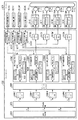
図3は、本実施の形態において行われる走査線の傾き、湾曲により発生する色ずれを補正する色ずれ補正処理を説明するためのブロック図である。 FIG. 3 is a block diagram for explaining color misregistration correction processing for correcting color misregistration caused by the inclination and curvature of the scanning line performed in the present embodiment.
301はプリンタエンジンで、図1に示す像形成部を有し、コントローラ302で生成されたビットマップのイメージデータを基に印刷処理を行う。303C,303Y,303M,303Kのそれぞれは、シアン、イエロー、マゼンタ、黒の色毎の色ずれ量(形成される像の位置ずれ量であるが、これが色ずれの原因となるので以下、色ずれ量とする)を記憶する色ずれ量記憶部で、各色毎に、上述した領域ごとの主走査線のずれ量を記憶する。本実施の形態では、図2で説明した、複数のポイントで測定した実際の主走査線202の位置を基に、理想的な主走査線201に対する副走査方向のずれ量を、主走査線202の傾き及び湾曲を示す情報として色ずれ量記憶部303に記憶する。
A
図4は、この色ずれ量記憶部303(303C,303Y,303M,303K)に記憶されるデータ例を示す図である。 FIG. 4 is a diagram showing an example of data stored in the color misregistration amount storage unit 303 (303C, 303Y, 303M, 303K).
図4では、図2に示す各領域ごとに、基準点から実際に測定した主走査線202上の点までの主走査方向の長さ(L1,L2,L3)と、主走査線202上の点(Pb,Pc,Pd)と理想的な主走査線201とのずれ量(m1,m2,m3)とが対応付けられて、いずれもmm単位で記憶されている。尚、L1,L2,L3のそれぞれは、基準点(ポイントA)から領域1、領域2及び領域3の終端までのそれぞれの長さを表している。またm1,m2,m3のそれぞれは、領域1、領域2、領域3の各終端における理想的な主走査線201と、実際の主走査線202のずれ量である。
In FIG. 4, for each region shown in FIG. 2, the length (
次に、コントローラ302において、色ずれ量記憶部303に記憶された主走査線のずれ量を相殺するように画像データを補正して印刷処理を行う動作を説明する。
Next, an operation in the
画像生成部304は、コンピュータ装置等の外部機器(不図示)から受信する印刷データに基づいて印刷処理が可能なラスタイメージデータを生成し、RGBデータとしてドット毎に出力する。色変換部305は、そのRGBデータを、プリンタエンジン301で処理可能なCMYK色空間のデータに変換する。ハーフトーン処理部309C〜309Kのそれぞれは、所定のハーフトーンスクリーンパターンを用いて、入力するドットデータのビット数を削減し、ドット単位の階調表現からハーフトーンスクリーンの面積単位での階調表現のデータに変換する。こうして変換されたデータは、ビットマップメモリ406に色毎に蓄積される。このビットマップメモリ306は、印刷処理を行うラスタイメージデータを一旦蓄積するものであり、1ページ分のイメージデータを蓄積するページメモリ、又は複数ライン分のデータを記憶するバンドメモリの少なくともいずれかを備えていても良い。
The
307C,307Y,307M,307Kのそれぞれは、各色データに対応する色ずれの補正量を算出する色ずれ補正量演算部であり、各色に対応する色ずれ量記憶部303に記憶された主走査線のずれ量を示す情報に基づき、各ドット毎に、後述する色ずれ補正部308(308C,308Y,308M,308K)から指示される主走査方向の座標情報に対応した副走査方向の色ずれ補正量を算出して、各色ずれ補正部308にそれぞれ出力する。 Each of 307C, 307Y, 307M, and 307K is a color misregistration correction amount calculation unit that calculates a color misregistration correction amount corresponding to each color data, and the main scanning line stored in the color misregistration amount storage unit 303 corresponding to each color. Based on the information indicating the amount of misregistration, color misregistration correction in the sub-scanning direction corresponding to coordinate information in the main scanning direction instructed from a color misregistration correction unit 308 (308C, 308Y, 308M, 308K) described later for each dot. The amount is calculated and output to each color misregistration correction unit 308.
いま、あるドットに対する主走査方向の座標をx(ドット)、副走査方向をyラインとし、副走査方向の色ずれ補正量をΔyi(ドット)(iは、領域を表す)とした場合、図2を基にした各領域における副走査方向の色ずれ補正量Δyiの演算式を以下に示す(尚、ここでは解像度を600dpiとする)。 Now, assuming that the coordinate in the main scanning direction for a certain dot is x (dot), the sub-scanning direction is y-line, and the color misregistration correction amount in the sub-scanning direction is Δyi (dot) (i represents a region) An arithmetic expression of the color misregistration correction amount Δyi in the sub-scanning direction in each region based on 2 is shown below (here, the resolution is 600 dpi).
領域1:Δy1=x×(m1/L1) …式(1)
領域2:Δy2=m1×23.622+(x−L1×23.622)×((m2−m1)/(L2−L1)) …式(2)
領域3:Δy3=m2×23.622+(x−L2×23.622)×((m3−m2)/(L3−L2)) …式(3)
色ずれ補正部308C,308Y,308M,308Kのそれぞれは、主走査線の傾きや歪みによる色ずれを補正している。具体的には、色ずれ補正量演算部307C,307Y,307M,307Kのそれぞれによってドット毎に算出される色ずれ補正量に基づいて、ビットマップメモリ306に蓄積されたビットマップデータの出力タイミングの調整及び各ドット毎の露光量の調整を行っている。これにより各色のトナー像を、転写シートに転写したときの色ずれ(レジストレーションずれ)を防止している。
Region 1: Δy1 = xx (m1 / L1) (1)
Region 2: Δy2 = m1 × 23.622 + (x−L1 × 23.622) × ((m2−m1) / (L2−L1)) (2)
Region 3: Δy3 = m2 × 23.622 + (x−L2 × 23.622) × ((m3−m2) / (L3−L2)) Equation (3)
Each of the color
次に本実施の形態に係る色ずれ補正部308(308C,308Y,308M,308K)を図5に示すブロック図を参照して説明する。尚、ここではシアン用の色ずれ量補正部308Cの場合で説明するが、他の色様の色ずれ量補正部の構成及び動作も同様であるため、それらの説明を省略する。
Next, the color misregistration correction unit 308 (308C, 308Y, 308M, 308K) according to the present embodiment will be described with reference to the block diagram shown in FIG. Here, the description will be given in the case of the color
色ずれ補正部308Cは、座標カウンタ801、座標変換部802、ラインバッファ803、階調補正部804を有している。座標カウンタ801は、色ずれ補正処理の対象となるドットの主走査方向及び副走査方向の座標データを座標変換部802に出力する。これと同時に、そのドットの主走査方向の座標データを、色ずれ量演算部307C及び階調補正部804に出力する。座標変換部802は、座標カウンタ801から入力される主走査方向及び副走査方向の座標データとに基づいて、ビットマップメモリ306から、処理対象のラインデータを読み出す。階調補正部804は、色ずれ補正量演算部307Cより得られるずれ補正量Δyに基づき、このずれ補正量Δyの整数部分に基づく補正処理、つまりドット単位での副走査方向に対する再構成処理を行う。また階調補正部804は、座標カウンタ801からの主走査方向の座標データとずれ補正量Δyに基づき、このずれ補正量Δyの小数点以下の値に基づく補正処理、つまりドット単位未満での補正を、副走査方向の前後のドットの露光比率を調整して行う。また階調補正部804は、副走査方向の前後のドットを参照するためのラインバッファ803を用いる。
The color
以上の構成に基づく動作を以下に説明する。 The operation based on the above configuration will be described below.
座標変換部802は、座標カウンタ801から入力される座標値の副走査方向のアドレスを変換し、ビットマップメモリ306から対応するラインのビットマップデータを読み出す。ラインバッファ803は、処理対象のドットデータを記憶するレジスタ805と、先行する1ライン分のドットデータを記憶するFIFOバッファ806とを備えている。階調補正部804は、補正データを生成するために、ラインバッファ803に記憶されている副走査方向の前後のラインにあるドットデータを参照する。レジスタ805に蓄積されたドットデータは、階調補正部804に出力されるとともに、次のラインの補正データの生成に使用される。階調補正部804は、座標カウンタ801から入力されるnラインの主走査方向の座標x、レジスタ805から入力する、nラインのx番目のドットデータPn(x)、FIFOバッファ806から入力する先行するラインのx番目のドットデータPn-1(x)を入力している。そして、補正データP''n(x)を生成するために、以下の演算処理を行う。
The coordinate
P'n(x)=Pn(x)×β(x)+Pn-1(x)×α(x)
濃度確認部804bは、処理対象のドットデータPn(x)を入力し、そのドットの濃度を確認する。このドットPn(x)の濃度が、所定の濃度値(μ)よりも低いときにはP''n(x)として元のドットデータPn(x)を出力し、所定の濃度値(μ)よりも高いときには、補正したドットデータP'n(x)を選択して出力する。この選択は、セレクタ804aにより行われる。このようにして、副走査方向のドット単位未満の色ずれ量を補正したビットマップデータが出力される。
P′n (x) = Pn (x) × β (x) + Pn−1 (x) × α (x)
The
こうしてずれ量が補正されたドットデータは、PWM回路310C〜310Kによりパルス幅変調された信号に変換され、この信号が、それぞれ対応する露光ユニット51C〜51Kに送られて、各半導体レーザを駆動する。
The dot data in which the shift amount is corrected in this way is converted into a pulse-width modulated signal by the PWM circuits 310C to 310K, and this signal is sent to the
図6は、本実施の形態に係る座標変換部802が、色ずれ補正量Δyの整数部分に基づくずれ量を補正する動作を説明するためのイメージ図である。
FIG. 6 is an image diagram for explaining an operation in which the coordinate
座標変換部802は、600で示すように、直線で近似された主走査線の色ずれ情報から求められる色ずれ補正量Δyの整数部分の値に応じて、ビットマップメモリ306に蓄積された、そのドットデータの副走査方向(Y方向)の座標をオフセットする。例えば601に示すように、座標カウンタ801からの副走査方向の座標がn(ライン)の場合、主走査方向の座標をxとすると、主走査方向のx座標において、(1)の領域では、色ずれ補正量Δyが0以上1未満である。よって、この場合には、nライン目のデータを再構成する場合、ビットマップメモリ306からnライン目のドットデータ610を読み出す(オフセット=0)。(2)の領域では、色ずれ補正量Δyが1以上2未満であるため、nライン目のデータを再構成する場合、副走査ライン数を1だけオフセットした(n+1)ラインのデータ611を読み出すための座標変換処理が行われる。同様に(3)の領域では、色ずれ補正量Δyが2以上3未満であるため(n+2)ライン目のデータ612を読み出すための座標変換処理が実行される。以下同様にして、(4)の領域では(n+3)ライン目のデータを読み出すため座標変換処理が行われ、(5)の領域では(n+4)ライン目のデータを読み出すため座標変換処理が行われる。
The coordinate
以上の方法により、ずれ補正量の整数部分の値に従って、副走査方向のライン単位、即ち、ドット単位での再構成処理が行われる。尚、602は、座標変換部802によりドット単位での色ずれ補正を行ったデータ601を基に、感光ドラムに露光した場合の露光イメージを示している。
With the above method, reconstruction processing is performed in units of lines in the sub-scanning direction, that is, in units of dots, according to the value of the integer part of the deviation correction amount.
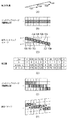
図7(A)〜(F)は、階調補正部804が行うドット単位未満の色ずれ補正、つまり色ずれ補正量Δyの小数点以下のずれ量を補正する動作内容を説明するためのイメージ図である。小数点以下のずれ量の補正は、副走査方向の前後のドットの露光比率を調整することにより行われる。
FIGS. 7A to 7F are image diagrams for explaining the operation of correcting the color misregistration performed by the
図7(A)は、右上がりの傾きを有する主走査線のイメージである。図7(B)は、このずれ補正前のビットマップイメージを示し、主走査方向に水平な直線のビットマップイメージである。図7(C)は、図7(A)に示す主走査線の傾きによる色ずれを相殺するために、図7(B)のビットマップイメージを補正した補正イメージである。 FIG. 7A is an image of a main scanning line having an upward slope. FIG. 7B shows a bitmap image before this deviation correction, and is a straight bitmap image horizontal in the main scanning direction. FIG. 7C is a correction image obtained by correcting the bitmap image of FIG. 7B in order to cancel the color shift due to the inclination of the main scanning line shown in FIG.
ここでは図7(C)に示す補正イメージを実現するために、副走査方向に位置している前後のラインにおけるドットの露光量を調整する。 Here, in order to realize the correction image shown in FIG. 7C, the exposure amount of dots in the front and rear lines positioned in the sub-scanning direction is adjusted.
図7(D)は、色ずれ補正量Δyと階調補正を行うための補正係数との関係を表している。kは色ずれ補正量Δyの整数部分(小数点以下を切り捨て)であり、図6で説明したドット単位での副走査方向の補正量を表わしている。βとαは、ドット単位未満(1ドットサイズよりも小さいサイズ)の副走査方向の補正を行うための補正係数で、色ずれ補正量Δyの小数点以下の情報より、副走査方向の前後のドットの露光量の分配率を表わす。これら補正係数α、βのそれぞれは、
α=Δy−k
β=1−α
により求められる。ここでαは、(n+k)ラインへのドットの分配率、βは(n+k−1)ラインへのドットの分配率を表す。即ち、k=0のときは、αは、nラインへのドットの分配率、βは(n−1)ラインへのドットの分配率を表わす。又k=1のときは、αは(n+1)ラインへのドットの分配率、βはnラインへのドットの分配率を表わす。
FIG. 7D shows the relationship between the color misregistration correction amount Δy and the correction coefficient for performing gradation correction. k is the integer part of the color misregistration correction amount Δy (the fractional part is rounded down), and represents the correction amount in the sub-scanning direction in dot units described with reference to FIG. β and α are correction coefficients for correcting in the sub-scanning direction less than a dot unit (size smaller than one dot size), and dots before and after the sub-scanning direction are determined from information below the decimal point of the color misregistration correction amount Δy. Represents the distribution ratio of the exposure amount. Each of these correction factors α, β is
α = Δy−k
β = 1−α
It is calculated by. Here, α represents the distribution ratio of dots to the (n + k) line, and β represents the distribution ratio of dots to the (n + k−1) line. That is, when k = 0, α represents the dot distribution ratio to the n line, and β represents the dot distribution ratio to the (n−1) line. When k = 1, α represents the dot distribution ratio to the (n + 1) line, and β represents the dot distribution ratio to the n line.
ここで、図7(C)〜(D)を参照して説明すると、ドット700は、図7(D)において、k=0,α=0,β=1であるため、本来位置しているnラインの1つ前の(n−1)ラインに移動して形成される。ドット701は、図7(D)において、α=0.25,β=0.75であるため、nラインの1つ前の(n−1)ラインで、そのドットの3/4が形成され、現ライン(n)では1/4のドットが形成される。同様にドット702は、図7(D)において、α=0.5,β=0.5であるため、nラインの1つ前の(n−1)ラインで、そのドットの1/2が形成され、現ライン(n)では1/2のドットが形成される。同様にドット703は、nラインの1つ前の(n−1)ラインで、そのドットの1/4が形成され、現ライン(n)では3/4のドットが形成される。尚、ドット704は、k=1,α=0,β=1であるため、本来位置しているnラインの位置に形成される。そしてドット705〜707ではk=1であるため、αは(n+1)ラインへのドットの分配率、βはnラインへのドットの分配率を表わしている。更にドット708ではk=2であるため、αは(n+2)ラインへのドットの分配率、βは(n+1)ラインへのドットの分配率を表わしている。
Here, with reference to FIGS. 7C to 7D, the
図7(E)は、図7(D)の補正係数に従って、副走査方向の前後のドットの露光比率を調整したビットマップイメージに基づくパルス信号として示している。ここでは各ドットデータに対応するパルス幅変調された信号の形式で示している。 FIG. 7E shows a pulse signal based on a bitmap image in which the exposure ratio of dots before and after the sub-scanning direction is adjusted in accordance with the correction coefficient shown in FIG. Here, a pulse width modulated signal corresponding to each dot data is shown.
図7(F)は、図7(E)で示すような階調補正されたパルス幅でレーザ露光された場合に感光ドラムで現像されたイメージを示している。これにより、主走査ラインの傾きが相殺され、水平な直線が形成されることになる。 FIG. 7F shows an image developed on the photosensitive drum when the laser exposure is performed with the tone-corrected pulse width as shown in FIG. Thereby, the inclination of the main scanning line is canceled and a horizontal straight line is formed.
以上の説明では、ハードウェアによる補正処理として説明したが、コントローラ302にCPUを備えることによりソフトウェアによる処理も可能である。
In the above description, correction processing by hardware has been described, but processing by software is also possible by providing the
図8は、図3に示すコントローラ302をCPUとメモリで構成した例を示すブロック図で、前述の図3と共通する部分は同じ記号で示し、その説明を省略する。
FIG. 8 is a block diagram showing an example in which the
プリンタエンジン301は図3と同じ構成で、ここでは露光ユニット51や感光ドラム14などは省略して示している。色ずれ量記憶部303C〜303Kのそれぞれは、前述したように、各色に対応する感光ドラム14C〜14Kのそれぞれにおける色ずれ量を記憶している。コントローラ302は、CPU1000、CPU1000により実行されるプログラムや各種データを記憶するROM1001、CPU1000による制御処理時にワークエリアとして使用され、各種データを一時的に保存するRAM1002を備えている。このRAM1002には、シアン、イエロー、マゼンタ、黒の各ビットマップイメージデータを記憶しているビットマップメモリ306、プリンタエンジン301の色ずれ量記憶部303C〜303Kから取得した、各色に対応する色ずれデータを記憶するエリア1010が設けられている。
The
図9及び図10は、本実施の形態に係るコントローラ302のCPU1000により実行される像形成処理を説明するフローチャートで、この処理を実行するプログラムはROM1001に記憶されており、CPU1000の制御の下に実行される。
FIG. 9 and FIG. 10 are flowcharts for explaining the image forming process executed by the
まずステップS1で、プリンタエンジン301の色ずれ量記憶部303C〜303Kに格納されている各色ごとの色ずれ量を読み出してRAM1002のエリア1010に記憶する。次にステップS2で、印刷データを入力し色変換などの処理を行った後、シアン、イエロー、マゼンタ及び黒の各1ページ分のビットマップイメージデータに変換してビットマップメモリ306に記憶する。次にステップS3で、ライン数を計数する変数nを「1」に、ドット位置(x座標)を計数する変数xを「0」にそれぞれ初期化する。尚、これら変数は共にRAM1002に記憶される。
First, in step S <b> 1, the color misregistration amount for each color stored in the color misregistration amount storage units 303 </ b> C to 303 </ b> K of the
次にステップS4で、まず最初にシアンのビットマップデータのnライン目でx番目のドットデータを読み出す。そしてステップS5で、そのドットが含まれる領域(例えば、図2の領域1〜3のいずれか)を判定する。そしてステップS6で、ステップS5で判定した領域と、ドット位置(x)とに基づいて、そのドットを形成する副走査方向の補正量Δyを算出する。これは上述した式(1)〜(3)のいずれかにより求められる。そしてステップS7で、ステップS6で求めた補正量Δyの整数部分が「0」かどうかを判定する。「0」であれば、ライン単位での補正が不要であるためステップS10aに進むが、「0」でないときはステップS8に進み、その整数部分が正か負かを判断する。正であればステップS9に進み、(n+s)ラインのx番目のドットデータを取得して、現ラインのドットデータとする(図6参照)。一方、ステップS8で負であればステップS10に進み、(n−s)ラインのx番目のドットデータを取得して、現ラインのドットデータとする(図6参照)。尚、ここでsは、その整数部分の絶対値を示している。こうしてステップS9或はS10を実行するとステップS10aに進む。ステップS10aでは、その処理対象となっているドットデータ(多値データ)の濃度が所定濃度(μ)よりも小さいかどうかを判定する。これは前述した図5の階調確認部804bの構成に相当している。ここで濃度値が、閾値(μ)よりも小さいときは、前述した係数α、βを用いた補正が不要であると判断してステップS12に進むが、濃度値が、閾値(μ)よりも大きいときは、そのドットが形成されると目立つために、前述したずれ補正が必要であると判断してステップS11に進む。
In step S4, x-th dot data is first read out on the n-th line of cyan bitmap data. In step S5, an area including the dot (for example, any one of
ステップS11では、今度は補正量Δyの小数点以下の数値に対する処理を実行する。ここでは、その小数点以下の数値に従って、現ライン(nライン)と(n+1)ライン、或は(n−1)ラインの同じx番目のドットデータとの配分を決定する。ここでは図7を参照して前述したように、Sの小数点以下の数値に応じて、隣接するラインのドットデータとの間で、ドットデータの交換や入れ替えなどを行う。こうして現ライン(nライン)のx番目のドットデータが更新されるとステップS12で、ビットマップデータを更新する。次にステップS13で、変数xを+1し、次にステップS14で、その変数xの値が1ラインの全ドット数よりも大きくなったかどうかを判定し、大きくないときはステップS4に戻り、前述の処理を実行する。 In step S11, a process for the numerical value after the decimal point of the correction amount Δy is executed. Here, the distribution of the same x-th dot data in the current line (n line) and (n + 1) line or (n-1) line is determined according to the value after the decimal point. Here, as described above with reference to FIG. 7, the dot data is exchanged or exchanged with the dot data of the adjacent line according to the numerical value after the decimal point of S. When the x-th dot data of the current line (n line) is updated in this way, the bitmap data is updated in step S12. Next, in step S13, the variable x is incremented by 1, and then in step S14, it is determined whether or not the value of the variable x has become larger than the total number of dots in one line. Execute the process.
ステップS14で、その変数xの値が1ラインの全ドット数よりも大きくなるとステップS15に進み、ライン数をカウントする変数nを+1する。そしてステップS16で、この変数nの値が1ページのライン数を越えたかどうかを判定し、超えていないときはステップS17に進み、変数xを「0」に戻してステップS4に進み、前述した処理を実行する。一方、ステップS16で、変数nの値が1ページのライン数を越えるとステップS18に進み、シアン、イエロー、マゼンタ、黒のビットマップデータに対する処理が終了したかを調べ、終了していないときはステップS3に進んで前述の処理を実行するが、終了するとステップS19に進み像形成処理を開始する。 If the value of the variable x becomes larger than the total number of dots in one line in step S14, the process proceeds to step S15, and the variable n for counting the number of lines is incremented by one. In step S16, it is determined whether or not the value of the variable n has exceeded the number of lines on one page. If not, the process proceeds to step S17, the variable x is returned to “0”, and the process proceeds to step S4. Execute the process. On the other hand, if the value of the variable n exceeds the number of lines on one page in step S16, the process proceeds to step S18, where it is checked whether or not the processing for cyan, yellow, magenta, and black bitmap data has been completed. The process proceeds to step S3 to execute the above-described process. When the process is completed, the process proceeds to step S19 to start the image forming process.
ステップS19では、転写シートをカセット53からピックアップして搬送を開始し、搬送ベルト10上に載置して搬送しながら、ドットデータをPWM変調し、そのPWM信号により各半導体レーザを駆動してシアン、イエロー、マゼンタ、黒の順に順次トナー画像を形成し(ステップS20)、搬送されてくる転写シートに順次転写する。こうして転写が完了するとステップS22で、転写シートへの画像の定着を行い、定着が完了するとステップS23で、その定着済の転写シートを排紙する。
In step S19, the transfer sheet is picked up from the
尚、上述した閾値(μ)は、色毎、又は各ビームごとに設定をしてもよい。例えば、イエローのように濃度の差が人の目には判別しづらい色の場合には、閾値μを他の色の場合よりも、より大きく設定する。これにより、階調補正を実行する割合を他の色に比べて少なくすることで、モアレを解消することが可能である。 Note that the threshold value (μ) described above may be set for each color or for each beam. For example, in the case of a color whose density difference is difficult to be discerned by human eyes, such as yellow, the threshold value μ is set larger than in the case of other colors. Accordingly, it is possible to eliminate moire by reducing the ratio of executing the gradation correction as compared with other colors.
このように本実施の形態に係るカラー画像形成装置によれば、各感光ドラムにおける色ずれ量に基づいて、ドット単位での色ずれと、ドット単位に満たない量の色ずれの両方を補正できる。これにより、各感光ドラムを走査露光する走査線の傾きや、湾曲などに起因する、各色の画像における色ずれを防止して良好なカラー画像を得ることができる。 As described above, according to the color image forming apparatus of the present embodiment, it is possible to correct both color misregistration in dot units and color misregistration that is less than dot units based on the color misregistration amount in each photosensitive drum. . As a result, it is possible to prevent color misregistration in each color image due to the inclination or curvature of the scanning line for scanning exposure of each photosensitive drum, and obtain a good color image.
なお本発明は、前述した実施の形態の機能を実現するソフトウェアのプログラムを、システム或いは装置に直接或いは遠隔から供給し、そのシステム或いは装置のコンピュータが、その供給されたプログラムコードを読み出して実行することによっても達成される場合を含む。その場合、プログラムの機能を有していれば、その形態はプログラムである必要はない。従って、本発明の機能処理をコンピュータで実現するために、該コンピュータにインストールされるプログラムコード自体も本発明を実現するものである。つまり、本発明には、本発明の機能処理を実現するためのコンピュータプログラム自体も含まれる。その場合、プログラムの機能を有していれば、オブジェクトコード、インタプリタにより実行されるプログラム、OSに供給するスクリプトデータ等、プログラムの形態を問わない。 In the present invention, a software program that realizes the functions of the above-described embodiments is supplied directly or remotely to a system or apparatus, and the computer of the system or apparatus reads and executes the supplied program code. In some cases, it can be achieved by In that case, as long as it has the function of a program, the form does not need to be a program. Accordingly, since the functions of the present invention are implemented by computer, the program code installed in the computer also implements the present invention. That is, the present invention includes a computer program itself for realizing the functional processing of the present invention. In this case, the program may be in any form as long as it has a program function, such as an object code, a program executed by an interpreter, or script data supplied to the OS.
プログラムを供給するための記憶媒体としては、例えば、フロッピー(登録商標)ディスク、ハードディスク、光ディスク、光磁気ディスク、MO、CD−ROM、CD−R、CD−RW、磁気テープ、不揮発性のメモリカード、ROM、DVD(DVD−ROM,DVD−R)などがある。その他のプログラムの供給方法としては、クライアントコンピュータのブラウザを用いてインターネットのホームページに接続し、該ホームページから本発明のコンピュータプログラムそのもの、もしくは圧縮され自動インストール機能を含むファイルをハードディスク等の記憶媒体にダウンロードすることによっても供給できる。また本発明のプログラムを構成するプログラムコードを複数のファイルに分割し、それぞれのファイルを異なるホームページからダウンロードすることによっても実現可能である。つまり本発明の機能処理をコンピュータで実現するためのプログラムファイルを複数のユーザに対してダウンロードさせるWWWサーバも、本発明のクレームに含まれるものである。 As a storage medium for supplying the program, for example, floppy (registered trademark) disk, hard disk, optical disk, magneto-optical disk, MO, CD-ROM, CD-R, CD-RW, magnetic tape, nonvolatile memory card ROM, DVD (DVD-ROM, DVD-R) and the like. As another program supply method, a client computer browser is used to connect to an Internet homepage, and the computer program of the present invention itself or a compressed file including an automatic installation function is downloaded from the homepage to a storage medium such as a hard disk. Can also be supplied. It can also be realized by dividing the program code constituting the program of the present invention into a plurality of files and downloading each file from a different homepage. That is, a WWW server that allows a plurality of users to download a program file for realizing the functional processing of the present invention on a computer is also included in the claims of the present invention.
また、本発明のプログラムを暗号化してCD−ROM等の記憶媒体に格納してユーザに配布し、所定の条件を満足するユーザに対してインターネットを介してホームページから暗号化を解く鍵情報をダウンロードさせ、その鍵情報を使用することにより暗号化されたプログラムを実行してコンピュータにインストールさせて実現することも可能である。 In addition, the program of the present invention is encrypted, stored in a storage medium such as a CD-ROM, distributed to users, and key information for decryption is downloaded from a homepage via the Internet to users who satisfy predetermined conditions. It is also possible to execute the encrypted program by using the key information and install the program on a computer.
またコンピュータが、読み出したプログラムを実行することによって、前述した実施形態の機能が実現される他、そのプログラムの指示に基づき、コンピュータ上で稼動しているOSなどが、実際の処理の一部又は全部を行ない、その処理によっても前述した実施形態の機能が実現され得る。 In addition to the functions of the above-described embodiments being realized by the computer executing the read program, the OS running on the computer based on the instruction of the program may be part of the actual processing or The functions of the above-described embodiment can also be realized by performing all the processing and performing the processing.
さらに、記録媒体から読み出されたプログラムが、コンピュータに挿入された機能拡張ボードやコンピュータに接続された機能拡張ユニットに備わるメモリに書き込まれた後、そのプログラムの指示に基づき、その機能拡張ボードや機能拡張ユニットに備わるCPUなどが実際の処理の一部又は全部を行ない、その処理によっても前述した実施形態の機能が実現される。 Furthermore, after the program read from the recording medium is written in a memory provided in a function expansion board inserted into the computer or a function expansion unit connected to the computer, the function expansion board or The CPU or the like provided in the function expansion unit performs part or all of the actual processing, and the functions of the above-described embodiments are realized by the processing.
Claims (5)
前記ずれ量記憶手段から得られるずれ量を基に、印刷データに基づくラスターイメージのドット単位のずれ補正を行なうずれ補正手段と、
処理対象のラスターイメージの濃度が閾値より低い場合、前記ずれ量記憶手段から得られる前記ずれ量に基づくドット単位未満のずれ補正を行なわず、前記処理対象のラスターイメージの濃度が前記閾値以上の場合、前記ずれ量記憶手段から得られる前記ずれ量に基づくドット単位未満のずれ補正を行なう補正手段と、
前記補正手段により補正されたドットに応じた画像を前記レーザにより形成する画像形成手段と、
を有することを特徴とするカラー画像形成装置。 A shift amount storage means for storing a shift amount of an ideal main scanning line of the laser with respect to the photosensitive member;
Based on the shift amount obtained from the shift amount storage unit, a shift correction unit that performs shift correction in dot units of a raster image based on print data; and
When the density of the raster image to be processed is lower than the threshold, when the density of the raster image to be processed is equal to or higher than the threshold without performing shift correction less than a dot unit based on the shift amount obtained from the shift amount storage unit Correcting means for correcting a shift of less than a dot unit based on the shift amount obtained from the shift amount storage means;
Image forming means for forming an image corresponding to the dot corrected by the correcting means with the laser; and
A color image forming apparatus comprising:
感光体に対するレーザの理想的な主走査線に対するずれ量を記憶するずれ量記憶部から得られるずれ量を基に、印刷データに基づくラスターイメージのドット単位のずれ補正を行なうずれ補正工程と、A shift correction step for correcting a shift in dot units of a raster image based on print data based on a shift amount obtained from a shift amount storage unit that stores a shift amount of the laser with respect to the ideal main scanning line of the laser with respect to the photosensitive member;
処理対象のラスターイメージの濃度が閾値より低い場合、前記ずれ量記憶部から得られる前記ずれ量に基づくドット単位未満のずれ補正を行なわず、前記処理対象のラスターイメージの濃度が前記閾値以上の場合、前記ずれ量記憶手段から得られる前記ずれ量に基づくドット単位未満のずれ補正を行なう補正工程と、When the density of the raster image to be processed is lower than the threshold value, when the density of the raster image to be processed is equal to or higher than the threshold value without performing the dot correction based on the shift amount obtained from the shift amount storage unit. A correction step for correcting a shift of less than a dot unit based on the shift amount obtained from the shift amount storage means;
前記補正工程で補正されたドットに応じた画像を前記レーザにより形成する画像形成工程と、An image forming step of forming an image corresponding to the dot corrected in the correction step with the laser; and
を有することを特徴とするカラー画像形成装置の制御方法。A control method for a color image forming apparatus, comprising:
Priority Applications (6)
| Application Number | Priority Date | Filing Date | Title |
|---|---|---|---|
| JP2005118975A JP4533222B2 (en) | 2005-04-15 | 2005-04-15 | Color image forming apparatus and control method thereof |
| EP06251973.1A EP1710999B1 (en) | 2005-04-08 | 2006-04-07 | Color image forming apparatus |
| US11/279,001 US7630100B2 (en) | 2005-04-08 | 2006-04-07 | Color image forming apparatus |
| CN200610072550XA CN1845014B (en) | 2005-04-08 | 2006-04-07 | Color image forming apparatus |
| KR1020060032209A KR100809969B1 (en) | 2005-04-08 | 2006-04-10 | Col0r image forming apparatus and control method thereof |
| US12/603,035 US8068259B2 (en) | 2005-04-08 | 2009-10-21 | Color image forming apparatus |
Applications Claiming Priority (1)
| Application Number | Priority Date | Filing Date | Title |
|---|---|---|---|
| JP2005118975A JP4533222B2 (en) | 2005-04-15 | 2005-04-15 | Color image forming apparatus and control method thereof |
Publications (3)
| Publication Number | Publication Date |
|---|---|
| JP2006297631A JP2006297631A (en) | 2006-11-02 |
| JP2006297631A5 JP2006297631A5 (en) | 2008-05-29 |
| JP4533222B2 true JP4533222B2 (en) | 2010-09-01 |
Family
ID=37466311
Family Applications (1)
| Application Number | Title | Priority Date | Filing Date |
|---|---|---|---|
| JP2005118975A Expired - Fee Related JP4533222B2 (en) | 2005-04-08 | 2005-04-15 | Color image forming apparatus and control method thereof |
Country Status (1)
| Country | Link |
|---|---|
| JP (1) | JP4533222B2 (en) |
Families Citing this family (4)
| Publication number | Priority date | Publication date | Assignee | Title |
|---|---|---|---|---|
| JP4311753B2 (en) * | 2007-03-06 | 2009-08-12 | キヤノン株式会社 | Image forming apparatus and control method thereof |
| JP2013156547A (en) * | 2012-01-31 | 2013-08-15 | Canon Inc | Image forming apparatus |
| JP2013156548A (en) * | 2012-01-31 | 2013-08-15 | Canon Inc | Image forming apparatus |
| JP6611510B2 (en) * | 2015-08-05 | 2019-11-27 | キヤノン株式会社 | Correction method for image forming apparatus |
Citations (2)
| Publication number | Priority date | Publication date | Assignee | Title |
|---|---|---|---|---|
| JP2000015870A (en) * | 1998-07-03 | 2000-01-18 | Minolta Co Ltd | Image-processing apparatus |
| JP2004170755A (en) * | 2002-11-21 | 2004-06-17 | Canon Inc | Color image forming apparatus |
-
2005
- 2005-04-15 JP JP2005118975A patent/JP4533222B2/en not_active Expired - Fee Related
Patent Citations (2)
| Publication number | Priority date | Publication date | Assignee | Title |
|---|---|---|---|---|
| JP2000015870A (en) * | 1998-07-03 | 2000-01-18 | Minolta Co Ltd | Image-processing apparatus |
| JP2004170755A (en) * | 2002-11-21 | 2004-06-17 | Canon Inc | Color image forming apparatus |
Also Published As
| Publication number | Publication date |
|---|---|
| JP2006297631A (en) | 2006-11-02 |
Similar Documents
| Publication | Publication Date | Title |
|---|---|---|
| JP2006289749A (en) | Color image forming apparatus | |
| US8040580B2 (en) | Image forming apparatus, control method therefor, and computer program | |
| US20070097439A1 (en) | Image processing method and apparatus thereof | |
| JP2007121923A (en) | Image forming apparatus, control method therefor, and program | |
| US8619322B2 (en) | Image formation apparatus and image formation method for performing color deviation correction | |
| JP4673192B2 (en) | Image processing apparatus and image processing apparatus control method | |
| JP4612859B2 (en) | Image forming apparatus, control method therefor, and computer program | |
| JP4612860B2 (en) | Image forming apparatus, control method therefor, and computer program | |
| JP4533222B2 (en) | Color image forming apparatus and control method thereof | |
| JP4667201B2 (en) | Image forming apparatus and control method thereof | |
| US8335026B2 (en) | Image forming apparatus and color shift correction method thereof | |
| JP4459039B2 (en) | Image forming apparatus and control method thereof | |
| JP4420457B2 (en) | Image forming apparatus, control method therefor, computer program, and storage medium | |
| JP5404340B2 (en) | Image forming apparatus, image forming method, and program | |
| JP4926412B2 (en) | Image processing apparatus, control method therefor, and program | |
| JP2006162698A (en) | Image forming apparatus and its control method | |
| JP4950562B2 (en) | Color image forming apparatus and control method thereof | |
| JP4898292B2 (en) | Image forming apparatus, image forming method, and program | |
| JP2004188665A (en) | Image forming apparatus, correction data generating unit, and method for correcting amount of light of optical printhead | |
| RU2304808C1 (en) | Image generation device and method for controlling said device | |
| JP4459038B2 (en) | Image forming apparatus and control method thereof | |
| JP2007279238A (en) | Image forming apparatus and image forming method | |
| JP2006292967A (en) | Color image forming apparatus | |
| JP4939660B2 (en) | Image forming apparatus and control method thereof | |
| US6486973B1 (en) | Image forming apparatus and method for correcting density level of pixel data corresponding to each dot in a dot image |
Legal Events
| Date | Code | Title | Description |
|---|---|---|---|
| A521 | Request for written amendment filed |
Free format text: JAPANESE INTERMEDIATE CODE: A523 Effective date: 20080415 |
|
| A621 | Written request for application examination |
Free format text: JAPANESE INTERMEDIATE CODE: A621 Effective date: 20080415 |
|
| A977 | Report on retrieval |
Free format text: JAPANESE INTERMEDIATE CODE: A971007 Effective date: 20100525 |
|
| TRDD | Decision of grant or rejection written | ||
| A01 | Written decision to grant a patent or to grant a registration (utility model) |
Free format text: JAPANESE INTERMEDIATE CODE: A01 Effective date: 20100531 |
|
| A01 | Written decision to grant a patent or to grant a registration (utility model) |
Free format text: JAPANESE INTERMEDIATE CODE: A01 |
|
| A61 | First payment of annual fees (during grant procedure) |
Free format text: JAPANESE INTERMEDIATE CODE: A61 Effective date: 20100611 |
|
| R150 | Certificate of patent or registration of utility model |
Ref document number: 4533222 Country of ref document: JP Free format text: JAPANESE INTERMEDIATE CODE: R150 Free format text: JAPANESE INTERMEDIATE CODE: R150 |
|
| FPAY | Renewal fee payment (event date is renewal date of database) |
Free format text: PAYMENT UNTIL: 20130618 Year of fee payment: 3 |
|
| LAPS | Cancellation because of no payment of annual fees |