JP5424761B2 - Seismic reinforcement method for existing buildings - Google Patents
Seismic reinforcement method for existing buildings Download PDFInfo
- Publication number
- JP5424761B2 JP5424761B2 JP2009172460A JP2009172460A JP5424761B2 JP 5424761 B2 JP5424761 B2 JP 5424761B2 JP 2009172460 A JP2009172460 A JP 2009172460A JP 2009172460 A JP2009172460 A JP 2009172460A JP 5424761 B2 JP5424761 B2 JP 5424761B2
- Authority
- JP
- Japan
- Prior art keywords
- column
- pillar
- existing building
- outer peripheral
- seismic reinforcement
- Prior art date
- Legal status (The legal status is an assumption and is not a legal conclusion. Google has not performed a legal analysis and makes no representation as to the accuracy of the status listed.)
- Expired - Fee Related
Links
Images


Description
本発明は、既存建物の耐震補強方法に関する。 The present invention relates to a seismic reinforcement method for existing buildings.
耐震強度が不足している既存建物は、一般に、柱の打ち増しや、柱の周囲を鋼板や炭素繊維で取り囲む等の手段で耐震補強が行われている。特に、既存建物の外周部柱を従来の補強方法で補強する場合、外壁に影響が及ぶため大掛かりな工事となり、長い養生期間が必要となる等の問題が生じる。 Existing buildings with insufficient earthquake resistance are generally reinforced with earthquake resistance by means such as increasing the number of columns and surrounding the columns with steel plates or carbon fibers. In particular, when the outer peripheral column of an existing building is reinforced by a conventional reinforcing method, the outer wall is affected, so a large-scale construction is required, and a long curing period is required.
このとき、外壁にウォールガーダー形式の梁が採用されている場合には、外周部柱のせん断スパン比が小さくなり、外周部柱がせん断破壊を生じやすくなるため、十分な配慮が必要となる。
このため、簡易で施工性の良い耐震補強方法が求められている。
そこで、外周部柱を簡易に補強する耐震補強方法が提案されている(特許文献1)。
At this time, when a wall girder type beam is adopted for the outer wall, the shear span ratio of the outer peripheral column becomes small, and the outer peripheral column is liable to be sheared, so that sufficient consideration is required.
For this reason, there is a demand for a seismic reinforcement method that is simple and has good workability.
Then, the earthquake-proof reinforcement method which reinforces an outer peripheral part column simply is proposed (patent document 1).
特許文献1によれば、図5に示すように、鉄筋コンクリート造ラーメン構造の既存建物80には、外周部柱82の外側に、外周部柱82の外側壁面に沿わせて補強柱86を設けている。
According to Patent Document 1, as shown in FIG. 5, in an existing
補強柱86は、柱鉄骨90の内部にコンクリート88を充填させたいわゆるCFT柱とされ、既存建物80の場所に応じて、補強が必要な高さで設けられている。補強柱86と外周部柱82の接合は、外周部柱82に植設したシアキー84をアンカーとして使用し、補強柱86のコンクリート88に定着させて接合している。
The reinforcing
また、外周部梁94の外側には、鉄骨梁92が、既存建物80の場所に応じて、補強が必要な補強柱86の間に横方向に架けられている。鉄骨梁92の両端面は、補強柱86の柱鉄骨90の側壁と接合されている。これにより、既存建物80の外周部柱82が耐震補強される。
Further, on the outside of the outer
しかし、特許文献1の補強方法は、補強柱86に常に軸力が伝達されるので、大きな地震が発生した時に、外周部梁94と補強柱86が一緒にせん断破壊する恐れがある。また、既存建物80の外部での工事となるため、隣地との境界制限もある。
However, since the axial force is always transmitted to the reinforcing
本発明は、上記事実に鑑み、地震時に外周部柱がせん断破壊しても建物を支持できる、耐震補強方法を提供することを目的とする。 In view of the above facts, an object of the present invention is to provide a seismic reinforcement method capable of supporting a building even if an outer peripheral column is sheared and destroyed during an earthquake.
請求項1に記載の発明に係る既存建物の耐震補強方法は、既存建物の内部に設けられた内部柱の周囲を、鉛直方向に分割された補強部材で取り囲んだ後、分割位置を接合して補強し、前記既存建物の前記内部柱と対面する外周部柱の側面へ、地震時に軸力が伝達される添え柱を設けて補強することを特徴としている。 The seismic reinforcement method for an existing building according to the invention of claim 1 is to surround the inner pillar provided inside the existing building with a reinforcing member divided in the vertical direction, and then join the divided positions. Reinforcing and reinforcing a side column of the outer peripheral column facing the internal column of the existing building by providing an auxiliary column to transmit axial force during an earthquake.
請求項1に記載の発明によれば、内部柱は、鉛直方向に分割された補強部材で周囲を取り囲まれて接合され、耐震補強される。また、外周部柱は、内部柱と対面する外周部柱の側面に、地震時に軸力が伝達される添え柱を設けて耐震補強される。 According to the first aspect of the present invention, the inner pillar is surrounded and joined by the reinforcing member divided in the vertical direction to be seismically reinforced. Further, the outer peripheral column is seismically reinforced by providing an auxiliary column to which axial force is transmitted during an earthquake on the side surface of the outer peripheral column facing the inner column.
これにより、内部柱のみならず、外周部柱も外部での工事を必要とせずに耐震補強できる。このとき、外周部柱には何ら直接に加工を施す必要がなく、内部柱と対面する側面に添え柱を追加する作業のみとなり、施工性が良い。この結果、短期間で既存建物の耐震補強ができる。 Thereby, not only an internal pillar but an outer peripheral part pillar can carry out earthquake-proof reinforcement, without requiring the construction outside. At this time, it is not necessary to directly process the outer peripheral column, and only an additional column is added to the side surface facing the inner column, and the workability is good. As a result, existing buildings can be seismically strengthened in a short period of time.
請求項2に記載の発明は、請求項1に記載の既存建物の耐震補強方法において、前記添え柱は、前記既存建物の床スラブから上階の梁に至る長さとされ、前記添え柱の上端部には、前記外周部柱が支持する前記梁と接合される上側フランジが設けられ、下端部には、前記床スラブと接合される下側フランジが設けられ、前記梁と前記上側フランジの接合部の間、及び前記床スラブと前記下側フランジの接合部の間には、充填材を充填することを特徴としている。 The invention according to claim 2 is the seismic reinforcement method for an existing building according to claim 1, wherein the auxiliary pillar has a length from a floor slab of the existing building to a beam on an upper floor, and an upper end of the auxiliary pillar. The upper part is provided with an upper flange to be joined to the beam supported by the outer peripheral pillar, and the lower end is provided with a lower flange to be joined to the floor slab, and the beam and the upper flange are joined. It is characterized in that a filler is filled between the portions and between the joint portion of the floor slab and the lower flange.
請求項2に記載の発明によれば、添え柱は、既存建物の床スラブから上階の梁に至る長さを有し、添え柱の上端部には上側フランジが設けられ、添え柱の下端部には下側フランジが設けられている。そして、梁と上側フランジの接合部の間、及び床スラブと下側フランジの接合部の間には、充填材が充填されている。
これにより、梁が充填材を介して添え柱で支持される。
According to the invention described in claim 2, the splint has a length from the floor slab of the existing building to the beam on the upper floor, and an upper flange is provided at the upper end portion of the spear post, and the lower end of the spur post The part is provided with a lower flange. A filler is filled between the joint between the beam and the upper flange, and between the joint between the floor slab and the lower flange.
As a result, the beam is supported by the auxiliary pillar via the filler.
この結果、地震時以外は、充填材の収縮作用で、既存建物の荷重が添え柱に伝達されることはなく、内部柱と外周部柱が従来通り既存の建物を支持する。一方、地震時には、内部柱の損傷が、内部柱を取り囲む補強部材で抑制される。また、外周部柱が破損しても、添え柱が、外周部柱に替わり引き続き梁を支持する。これにより、既存建物の倒壊が防止される。 As a result, except during an earthquake, the load of the existing building is not transmitted to the auxiliary column due to the shrinkage of the filler, and the inner column and the outer column support the existing building as usual. On the other hand, during an earthquake, damage to the internal pillar is suppressed by the reinforcing member surrounding the internal pillar. In addition, even if the outer peripheral column is damaged, the accessory column replaces the outer peripheral column and continues to support the beam. Thereby, the collapse of the existing building is prevented.
請求項3に記載の発明は、請求項1又は2に記載の耐震補強方法において、前記添え柱は、内部にコンクリートが充填されたコンクリート充填柱であることを特徴としている。 The invention according to claim 3 is the seismic reinforcement method according to claim 1 or 2, wherein the auxiliary pillar is a concrete-filled pillar filled with concrete inside.
請求項3に記載の発明によれば、添え柱が内部にコンクリートが充填されたコンクリート充填柱とされている。 According to the third aspect of the present invention, the auxiliary column is a concrete-filled column in which concrete is filled.
添え柱をコンクリート充填柱とすることで、添え柱の支持強度を強くでき、既存建物の耐震強度をより高くできる。 By making the supporting column a concrete-filled column, the supporting strength of the supporting column can be increased, and the seismic strength of the existing building can be increased.
本発明は、上記構成としてあるので、地震時に外周部柱がせん断破壊しても、既存建物を支持できる。 Since this invention is set as the said structure, even if an outer peripheral part column shears and breaks at the time of an earthquake, it can support the existing building.
(第1の実施の形態)
図1に示すように、第1の実施の形態に係る既存建物の耐震補強方法は、既存建物10の柱を補強して耐震強度を高くする方法である。
既存建物10の柱には、大別すると既存建物10の内部に位置する内部柱12と、外周部に位置する外周部柱14の2種類がある。いずれも鉄筋コンクリート柱である。
(First embodiment)
As shown in FIG. 1, the seismic reinforcement method of the existing building which concerns on 1st Embodiment is a method which reinforces the pillar of the existing
The pillars of the existing
先ず、外周部柱14の補強について説明する。
外周部柱14の側面のうち、内部柱12と対面する側面14Nには、補強用の添え柱16が設けられている。
First, the reinforcement of the outer
Of the side surfaces of the outer
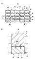
添え柱16は、図2に示すように、中空の鋼管柱(外形寸法D)とされ、外周部柱14の側面14Nから距離Sだけ離されて設けられている。また、添え柱16は、既存建物の床スラブ18から上階の梁20に至る長さとされている。
As shown in FIG. 2, the
なお、添え柱16の外形寸法Dと外周部柱14からの距離Sは、既存建物10が目標とする耐震強度を確保するために必要とする強度から決定される。即ち、既存の外周部柱14のせん断強度、添え柱16のせん断強度、添え柱16の取付け位置等により定まる値である。
The external dimension D of the
添え柱16は、上側の添え柱16Aと下側の添え柱16Bに2分割され、接合部16Cで接合されている。そして、上側の添え柱16Aの上端部には上側フランジ22が設けられ、上側フランジ22と上階の梁20がアンカーボルト30で接合されている。また、下側の添え柱16Bの下端部には下側フランジ24が設けられ、下側フランジ24と床スラブ18がアンカーボルト30で接合されている。
The
梁20と上側フランジ22の接合部の間、及び床スラブ18と下側フランジの接合部の間には、モルタル26が充填されている。これにより、添え柱16が上階の梁20を支持できる。なお、既存建物10の外壁38は、壁梁(ウオールガーダー)とされている。
このように、外周部柱14に添え柱16を設けることで、既存建物10の外部に、足場を組むことを必要とせずに、外周部柱14を耐震補強できる。更に、外周部柱14には何ら直接に加工を施す必要がなく、内部柱12と対面する側面14Nに添え柱16を追加する作業のみとなり施工性が良い。なお、外周部柱14のうち、隅柱15には添え柱16は設けられていない。
Thus, by providing the
次に、内部柱12の補強について説明する。
図3に示すように、内部柱12は、床スラブ18から上階の梁20の下面までの範囲に渡り、板厚T1の補強鋼板28で周囲を取り囲まれている。
Next, reinforcement of the
As shown in FIG. 3, the
補強鋼板28は、上側の補強鋼板28Aと下側の補強鋼板28Bに2分割され、更にそれぞれは、側方から内部柱12を囲めるように左右方向に2分割されている。そして、上側の補強鋼板28Aと下側の補強鋼板28Bで、内部柱12を側方から囲んだ後、接合部28C、28D、28Eで接合されている。
The reinforcing
なお、板厚T1は、内部柱12のせん断強度と既存建物10が目標とする耐震強度を確保するために必要とする強度から決定される。
内部柱12と補強鋼板28の隙間には、モルタル32が厚さT2で充填されている。これにより、内部柱12が補強鋼板28で耐震補強される。
In addition, plate | board thickness T1 is determined from the intensity | strength required in order to ensure the shear strength of the
A gap between the
以上説明したように、外周部柱14と内部柱12をそれぞれ補強することで、地震時以外は、モルタル26の収縮作用で、既存建物10の荷重が添え柱16に伝達されることはなく、内部柱12と外周部柱14が従来通り既存建物10を支持する。一方、地震時には、内部柱12の損傷が、内部柱14を取り囲む補強鋼板28で抑制される。
As explained above, by reinforcing each of the outer
また、外周部柱14が破損しても、添え柱16が、外周部柱14に替わり引き続き梁20を支持する。これにより、既存建物10の倒壊が防止される。
本実施の形態は、既存建物10の各階毎に採用することができる。
Further, even if the outer
This embodiment can be adopted for each floor of the existing
なお、内部柱12が所要のせん断強度を備えていないため、板厚T1の補強鋼板28で周囲を取り囲む構成としても、既存建物10が目標とする耐震強度を確保できないときは、外周部柱14と同じように、内部柱12の側壁に添え柱16を設けてもよい。
In addition, since the
(第2の実施の形態)
図4に示すように、第2の実施の形態に係る既存建物の耐震補強方法は、第1の実施の形態で説明した添え柱16を、コンクリート充填添え柱36としている。
(Second Embodiment)
As shown in FIG. 4, in the seismic reinforcement method for an existing building according to the second embodiment, the
コンクリート充填添え柱36は、添え柱16の内部にコンクリート34を充填している。これにより、コンクリート充填添え柱36の支持強度を強くできる。この結果、既存建物10の耐震強度をより高くできる。
他の構成は、第1の実施の形態と同一であり説明は省略する。
The concrete-filled supporting
Other configurations are the same as those of the first embodiment, and a description thereof will be omitted.
10 既存建物
12 内部柱
14 外周部柱
16 添え柱
18 床スラブ
20 梁
22 上側フランジ
24 下側フランジ
26 モルタル(充填材)
28 補強鋼板(補強部材)
34 コンクリート
36 コンクリート充填添え柱(コンクリート充填柱)
DESCRIPTION OF
28 Reinforced steel sheet (reinforcing member)
34
Claims (3)
前記既存建物の前記内部柱と対面する外周部柱の側面へ、地震時に軸力が伝達される添え柱を設けて補強する既存建物の耐震補強方法。 After surrounding the internal pillars provided inside the existing building with the reinforcing members divided in the vertical direction, the divided positions are joined and reinforced,
A method for seismic reinforcement of an existing building, in which a side post of an outer peripheral column facing the internal column of the existing building is provided and reinforced by an auxiliary column to transmit axial force during an earthquake.
前記添え柱の上端部には、前記外周部柱が支持する前記梁と接合される上側フランジが設けられ、下端部には、前記床スラブと接合される下側フランジが設けられ、
前記梁と前記上側フランジの接合部の間、及び前記床スラブと前記下側フランジの接合部の間には、充填材を充填する請求項1に記載の既存建物の耐震補強方法。 The splint is the length from the floor slab of the existing building to the beam on the upper floor,
An upper flange to be joined to the beam supported by the outer peripheral pillar is provided at the upper end of the accessory pillar, and a lower flange to be joined to the floor slab is provided at the lower end.
The seismic reinforcement method for an existing building according to claim 1, wherein a filler is filled between a joint between the beam and the upper flange and between a joint between the floor slab and the lower flange.
Priority Applications (1)
| Application Number | Priority Date | Filing Date | Title |
|---|---|---|---|
| JP2009172460A JP5424761B2 (en) | 2009-07-23 | 2009-07-23 | Seismic reinforcement method for existing buildings |
Applications Claiming Priority (1)
| Application Number | Priority Date | Filing Date | Title |
|---|---|---|---|
| JP2009172460A JP5424761B2 (en) | 2009-07-23 | 2009-07-23 | Seismic reinforcement method for existing buildings |
Publications (2)
| Publication Number | Publication Date |
|---|---|
| JP2011026811A JP2011026811A (en) | 2011-02-10 |
| JP5424761B2 true JP5424761B2 (en) | 2014-02-26 |
Family
ID=43635848
Family Applications (1)
| Application Number | Title | Priority Date | Filing Date |
|---|---|---|---|
| JP2009172460A Expired - Fee Related JP5424761B2 (en) | 2009-07-23 | 2009-07-23 | Seismic reinforcement method for existing buildings |
Country Status (1)
| Country | Link |
|---|---|
| JP (1) | JP5424761B2 (en) |
Families Citing this family (4)
| Publication number | Priority date | Publication date | Assignee | Title |
|---|---|---|---|---|
| JP5373848B2 (en) * | 2011-04-26 | 2013-12-18 | 旭コンクリート工業株式会社 | Method for reinforcing underground structure, column structure and concrete structure |
| JP6427315B2 (en) * | 2013-11-08 | 2018-11-21 | 株式会社竹中工務店 | Column reinforcement structure |
| JP2017115437A (en) * | 2015-12-24 | 2017-06-29 | 一般社団法人 レトロフィットジャパン協会 | Reinforcement method for building structure |
| KR101912116B1 (en) * | 2018-03-21 | 2018-10-29 | 주식회사 서린디앤씨 | Reinforcement structure and reinforcement structure installation method using the same |
Family Cites Families (7)
| Publication number | Priority date | Publication date | Assignee | Title |
|---|---|---|---|---|
| JPH108899A (en) * | 1996-06-21 | 1998-01-13 | Nippon Kokan Light Steel Kk | Structure reinforcing construction method and reinforcing column |
| JPH1046833A (en) * | 1996-07-31 | 1998-02-17 | Teito Kousokudo Kotsu Eidan | Earthquake-resistant reinforcing method of underground structure and earthquake-resistant reinforcing pole |
| JPH1077683A (en) * | 1996-09-03 | 1998-03-24 | Denki Kagaku Kogyo Kk | Joint structure of steel plate and reinforcement structure of structure with application of joint structure 0f the steel plate |
| JP2000087563A (en) * | 1998-09-11 | 2000-03-28 | Daito Kogyo Kk | Reinforcing and repairing structure and method of existing column |
| JP4350619B2 (en) * | 2004-08-30 | 2009-10-21 | 独立行政法人建築研究所 | Seismic retrofit structure of building and seismic retrofit method |
| JP5191191B2 (en) * | 2007-08-31 | 2013-04-24 | 株式会社竹中工務店 | Extension construction method of extension building |
| JP5132503B2 (en) * | 2008-09-22 | 2013-01-30 | 株式会社竹中工務店 | Seismic structure and building |
-
2009
- 2009-07-23 JP JP2009172460A patent/JP5424761B2/en not_active Expired - Fee Related
Also Published As
| Publication number | Publication date |
|---|---|
| JP2011026811A (en) | 2011-02-10 |
Similar Documents
| Publication | Publication Date | Title |
|---|---|---|
| KR101457077B1 (en) | Reformed concrete filled tube column structure | |
| CN109339229B (en) | Prefabricated assembled concrete-filled steel tube frame structure of perforation thick liquid anchor | |
| JP2010047910A (en) | Composite beam, construction method for the same, and fireproof building | |
| KR20180109766A (en) | E-z connecting structure for beam and column wherein the end-moment and bending resistibility are reinforced | |
| JP5424761B2 (en) | Seismic reinforcement method for existing buildings | |
| JP2010261270A (en) | Composite structure and method for constructing composite structure building | |
| JP6815183B2 (en) | Complex building | |
| JP2016050377A (en) | Joint structure between column base part and steel beam | |
| JP2011069148A (en) | Building structure | |
| JP2006316495A (en) | Foundation structure of bridge pier and its construction method | |
| JP4238991B2 (en) | Seismic isolation structure on the middle floor of the building | |
| JP2023029562A (en) | pile foundation structure | |
| JP6855296B2 (en) | Building foundation structure and its construction method | |
| JP6478832B2 (en) | Seismic reinforcement structure | |
| JP2006342497A (en) | Foundation structure of steel column base | |
| JP3981688B2 (en) | Joint structure and composite structure of steel beam and reinforced concrete column | |
| JP5344702B2 (en) | Column and slab joint structure | |
| JP6849491B2 (en) | Exposed column base structure of steel columns and its construction method | |
| JP2009257039A (en) | Aseismatic reinforcing method and aseismatic reinforcing structure for existing building | |
| JP2008223245A (en) | Column base structure | |
| JP4713218B2 (en) | Foundation structure | |
| JP4127225B2 (en) | Beam-column joint | |
| JP2006207306A (en) | Frame body, and connection structure of frame body and pile | |
| JP2007040049A (en) | Antiseismic reinforcing structure for existing building | |
| JP2007092370A (en) | Aseismatic reinforcing construction method of reinforced concrete existing building |
Legal Events
| Date | Code | Title | Description |
|---|---|---|---|
| A621 | Written request for application examination |
Free format text: JAPANESE INTERMEDIATE CODE: A621 Effective date: 20120627 |
|
| A977 | Report on retrieval |
Free format text: JAPANESE INTERMEDIATE CODE: A971007 Effective date: 20130710 |
|
| TRDD | Decision of grant or rejection written | ||
| A01 | Written decision to grant a patent or to grant a registration (utility model) |
Free format text: JAPANESE INTERMEDIATE CODE: A01 Effective date: 20131119 |
|
| A61 | First payment of annual fees (during grant procedure) |
Free format text: JAPANESE INTERMEDIATE CODE: A61 Effective date: 20131126 |
|
| R150 | Certificate of patent or registration of utility model |
Free format text: JAPANESE INTERMEDIATE CODE: R150 |
|
| LAPS | Cancellation because of no payment of annual fees |