JP5420900B2 - Rotor for electric machine - Google Patents
Rotor for electric machine Download PDFInfo
- Publication number
- JP5420900B2 JP5420900B2 JP2008519001A JP2008519001A JP5420900B2 JP 5420900 B2 JP5420900 B2 JP 5420900B2 JP 2008519001 A JP2008519001 A JP 2008519001A JP 2008519001 A JP2008519001 A JP 2008519001A JP 5420900 B2 JP5420900 B2 JP 5420900B2
- Authority
- JP
- Japan
- Prior art keywords
- rotor
- magnet
- slot
- arc
- rotor according
- Prior art date
- Legal status (The legal status is an assumption and is not a legal conclusion. Google has not performed a legal analysis and makes no representation as to the accuracy of the status listed.)
- Expired - Fee Related
Links
Images


Classifications
-
- H—ELECTRICITY
- H02—GENERATION; CONVERSION OR DISTRIBUTION OF ELECTRIC POWER
- H02K—DYNAMO-ELECTRIC MACHINES
- H02K1/00—Details of the magnetic circuit
- H02K1/06—Details of the magnetic circuit characterised by the shape, form or construction
- H02K1/22—Rotating parts of the magnetic circuit
- H02K1/27—Rotor cores with permanent magnets
- H02K1/2706—Inner rotors
- H02K1/272—Inner rotors the magnetisation axis of the magnets being perpendicular to the rotor axis
- H02K1/274—Inner rotors the magnetisation axis of the magnets being perpendicular to the rotor axis the rotor consisting of two or more circumferentially positioned magnets
- H02K1/2753—Inner rotors the magnetisation axis of the magnets being perpendicular to the rotor axis the rotor consisting of two or more circumferentially positioned magnets the rotor consisting of magnets or groups of magnets arranged with alternating polarity
- H02K1/276—Magnets embedded in the magnetic core, e.g. interior permanent magnets [IPM]
-
- H—ELECTRICITY
- H02—GENERATION; CONVERSION OR DISTRIBUTION OF ELECTRIC POWER
- H02K—DYNAMO-ELECTRIC MACHINES
- H02K1/00—Details of the magnetic circuit
- H02K1/06—Details of the magnetic circuit characterised by the shape, form or construction
- H02K1/22—Rotating parts of the magnetic circuit
- H02K1/27—Rotor cores with permanent magnets
-
- H—ELECTRICITY
- H02—GENERATION; CONVERSION OR DISTRIBUTION OF ELECTRIC POWER
- H02K—DYNAMO-ELECTRIC MACHINES
- H02K1/00—Details of the magnetic circuit
- H02K1/06—Details of the magnetic circuit characterised by the shape, form or construction
- H02K1/22—Rotating parts of the magnetic circuit
-
- H—ELECTRICITY
- H02—GENERATION; CONVERSION OR DISTRIBUTION OF ELECTRIC POWER
- H02K—DYNAMO-ELECTRIC MACHINES
- H02K29/00—Motors or generators having non-mechanical commutating devices, e.g. discharge tubes or semiconductor devices
- H02K29/03—Motors or generators having non-mechanical commutating devices, e.g. discharge tubes or semiconductor devices with a magnetic circuit specially adapted for avoiding torque ripples or self-starting problems
-
- H—ELECTRICITY
- H02—GENERATION; CONVERSION OR DISTRIBUTION OF ELECTRIC POWER
- H02K—DYNAMO-ELECTRIC MACHINES
- H02K2201/00—Specific aspects not provided for in the other groups of this subclass relating to the magnetic circuits
- H02K2201/06—Magnetic cores, or permanent magnets characterised by their skew
Description
本発明は、電気機械用のロータに関し、特に、ロータ自身に作られたスロットに配置された埋め込み永久磁石を有するロータに関する。 The present invention relates to a rotor for an electric machine, and more particularly to a rotor having an embedded permanent magnet disposed in a slot formed in the rotor itself.
ブラシレスモータで特に使用される既知の形式の埋め込み磁石ロータは、積層鉄心から構成され且つモータの回転軸と一致する主軸を有する鉄心から通常構成される。 Known types of embedded magnet rotors that are particularly used in brushless motors are typically constructed from a laminated core and a core having a main axis that coincides with the rotational axis of the motor.
ロータは、通常、主軸に平行な多数の縦向きのスロット、さらに、磁石と駆動軸とをそれぞれ適用するための主軸に平行な中心穴又は開口を有する。 The rotor typically has a number of longitudinal slots parallel to the main axis and a central hole or opening parallel to the main axis for applying the magnet and drive shaft, respectively.
ロータは、磁極に備え付けられた固定子(stator)に取り付けられ、給電されると、磁石と相互作用し、且つロータを回転させる磁場を生成する。 The rotor is attached to a stator attached to the magnetic pole, and when powered, interacts with the magnet and generates a magnetic field that rotates the rotor.
この種のロータを使用するモータの1つの欠点は、「コギングトルク(cogging torque)」又は「デタントトルク(detent torque)」と通常言われるものを生じさせるロータにおける磁石と、固定子上の極との間の磁力に起因する。 One drawback of motors that use this type of rotor is that the magnets in the rotor that produce what is commonly referred to as "cogging torque" or "detent torque", and the poles on the stator Due to the magnetic force between.
コギングトルクは、ロータの角速度における不均一さをもたらし、そういったロータは、円滑に且つ連続的に回転する代わりに、一連の短い「ガタガタ動作(jerky)」を伴って回転する傾向がある。 Cogging torque results in non-uniformities in the angular speed of the rotor, and such rotors tend to rotate with a series of short “jerky” instead of rotating smoothly and continuously.
埋め込み磁石ロータもまた、バランスさせること及び組み立てることが困難であり、特に、磁石を縦向きのスロットに挿入するのは困難である。
スロットの内側寸法は、磁石がスロットに挿入することができるように、磁石の外側寸法よりわずかに広い。
Embedded magnet rotors are also difficult to balance and assemble, and in particular, it is difficult to insert a magnet into a longitudinal slot.
The inner dimension of the slot is slightly wider than the outer dimension of the magnet so that the magnet can be inserted into the slot.
その結果として、従来技術のロータにおいては、スロットと磁石の間のこれらの小さな寸法的な差があり、磁石は、適切な位置に堅固に支えられず、かつ回転運動で生成される遠心力がスロットの最外壁に対して半径方向に磁石を押しつけることとなった。 As a result, in prior art rotors, there are these small dimensional differences between the slot and the magnet, the magnet is not firmly supported in place and the centrifugal force generated by the rotational motion is The magnet was pressed radially against the outermost wall of the slot.
これは、ロータが静止しているとき重量分散及び空隙が、ロータが回転しているときの重量分散及び空隙と異なることを意味する。
言い換えれば、モータが起動するとき、ロータ鉄心と磁石との相対的位置が変化し、モータ設計における電流及び配置を最適化するのが困難にさせる。
This means that the weight distribution and air gap are different when the rotor is stationary than the weight distribution and air gap when the rotor is rotating.
In other words, when the motor starts, the relative position of the rotor core and magnet changes, making it difficult to optimize the current and placement in the motor design.
配置の最適化は、ロータを形成する板が異なる回数切られるという原因による異なる板における同心度誤差による困難性でもある。これらの誤差は、ロータのアンバランスをもたらす。 Optimization of the arrangement is also a difficulty due to concentricity errors in different plates due to the fact that the plates forming the rotor are cut different times. These errors result in rotor imbalance.
このような状況において、本発明の主目的は、ロータが静止しているときの磁石の位置が、モータ起動時及びモータ回転開始時に変化しない組み立て容易な組み込み磁石ロータを提供することである。 Under such circumstances, the main object of the present invention is to provide an easily assembled magnet rotor in which the position of the magnet when the rotor is stationary does not change when the motor is started and when the motor starts rotating.
本発明の別な狙いは、静的及び回転状況の両方下でバランスした分散重量を有するロータを提供することである。 Another aim of the present invention is to provide a rotor having a distributed weight balanced under both static and rotational conditions.
本発明のさらに別な狙いは、モータ作動時にコギングトルクを減らすロータ、特にブラシレスモータ用ロータを提供することである。 Yet another object of the present invention is to provide a rotor, particularly a brushless motor rotor, that reduces cogging torque when the motor is operating.
上述の目的及び狙いは、独立項1及び14、もしくは1つ以上の従属項で規定される特徴を有する電気機械用ロータによって実質的に成し遂げられる。
The above objects and aims are substantially achieved by an electric machine rotor having the characteristics defined in
本発明のさらなる特性及び利点は、添付の図面で説明されるような電気機械用ロータの好適及び非限定的な実施形態を参照して、後述される詳細な説明でさらに明白である。 Additional features and advantages of the present invention will become more apparent from the detailed description set forth below with reference to preferred and non-limiting embodiments of an electric machine rotor as illustrated in the accompanying drawings.
添付図面を参照して、数字1は、本発明に係る電気モータM用のロータを示す。
Referring to the attached drawings,
図4及び6に表されるように、モータMは、ロータ1に適合する固定子200を備える。
ロータ1は、通常はモータMの軸と一致する回転Dの主軸を有し、及び、積層鉄心2、即ち、(「スタック技術」として知られるものによって組み立てられる)第1及び第2の壁4、5によって且つ側面6によって囲まれる結合要素3aで互いに堅く結合した多数の薄い積層3から構成される積層鉄心2を備える。
As shown in FIGS. 4 and 6, the motor M includes a
The
鉄心2は、モータ軸8と接続するために、その軸が主軸Dと実質的に一致する縦穴7を有する。
第1及び第2の壁4、5は、互いに平行であることが好ましい。この平行性を保障するために、積層3は、積層鉄心2を形成するために結合されるスタックの中に互いにグループ化される。
In order to connect to the
The first and
各スタックは、末端壁4、5の平行性を維持するためだけではなく、積層3が切られるとき変更されるスタック因子(stacking factor)を訂正するためにも、隣接するスタックと比して回転される。
Each stack rotates relative to the adjacent stack not only to maintain the parallelism of the
スタック因子訂正の目的は、積層鉄心2全体の間の抵抗を一定に保つためである。
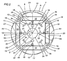
4極ロータ1を説明する図1及び2に表されるように、鉄心2は、各々が磁石10を収納する4つの縦スロット9も有する。
各磁石10は、ロータ1をより簡単にバランスさせるのに規定の重量を有する。
The purpose of stack factor correction is to keep the resistance between the entire laminated cores 2 constant.
As shown in FIGS. 1 and 2 describing the four-
Each
説明されない代替的実施形態では、磁石10は、磁場を最適化又は最大化するために、各スロット9より短い又は長い。
図3に表されるように、各スロット9は、各磁石10及び成形末端部15を適合するための中央ゾーン14を有し、成形末端部15は、中央ゾーン14に対して適切に曲げられる。
知られるように、これらの末端部15は、空であり、特に、スロット9に収納された各磁石10によって生成される磁束漏れの囲い込みを防ぐために使用される。
In an alternative embodiment not described, the
As shown in FIG. 3, each
As is known, these
末端部15では、各スロット9は、それぞれのスロット9の中に各磁石10を導くためのリブ(rib)16を有する。
磁石10は、磁石10自身をスロット9の中の横道を移動することを防ぐために、リブ16に対して隣接する。
図3a及び10で説明するように、リブ16は、スロット9の半径方向の内壁9a及び半径方向の外壁9bに各々作られる。
説明される好ましい実施形態では、リブ16は、半径Rの円形の形状であることに注意されたい。
At the
The
As illustrated in FIGS. 3 a and 10,
Note that in the preferred embodiment described, the
鉄心2の側面6は、互いに接続される多数の円弧11によって規定され、より詳細には、4極ロータ1の場合は、各積層3の側面は、半径R3の4つの弧11によって規定される。
記載の簡素化のために、1つの積層3でより詳細に検討すると、弧11の頂点12は、軸Dから等しい距離R1に配置され、主軸Dに実質的に垂直な軸D1に沿って配置され、それぞれの縦スロット9の中心線を通過する。
The
For simplicity of description, considering in more detail in one
基本的には、各弧11は、それぞれのスロット9に配置され、そして、隣接弧11は、直線部分13によって接続される。
1つの積層3(及び、結果的に、鉄心2)は、丸い角を有する多角形の形状を有する。
弧11の中心は、軸Dから均等な距離R2にある。
特に図2で説明されるように、弧11の中心は、より詳細に後述される空隙を通して磁束分散を最適化するために、縦穴7の境界24の内部に実質的に配置される。
Basically, each
One laminate 3 (and consequently the iron core 2) has a polygonal shape with rounded corners.
The center of the
In particular, as illustrated in FIG. 2, the center of the
例示及び発明の範囲を限定しない方法で、好ましい実施形態における4極ロータ内の各弧11は、主軸Dを参照して計測される約55°〜65°の間の角度Hに範囲を定める。より詳細には、好ましい実施形態における弧11によって範囲を定められる角度Hは、約60°である。
In a manner that does not limit the scope of the illustration and invention, each
図5に説明されるように、ロータ1の鉄心2は、実質的にT形状部及びゾーン25の一続きを有する。
ゾーン25は、上記接続部分13及び近接スロット9の末端部15によって囲まれる。
各ゾーン25は、軸D1に沿った半径方向に実質的に延びる幅Sの脚部26、及び、2つの連続した弧11を結合し、且つ、脚部26と実質的に垂直な方向に延びる幅S1のブリッジ27を有する。
As illustrated in FIG. 5, the iron core 2 of the
The
Each
特に、図3及び3bで説明したように、ロータ1は、磁石10をスロット9の中に保持し、かつモータMの作動時間中に磁石10が半径方向に移動することを防ぐための弾性固定手段17を備える。
手段17は、磁石10及び鉄心2の間に配置される弾性要素18を有する。
弾性要素18は、屈曲性のスプリング(リーフスプリング)から好ましくは構成される。スプリング18は、実質的に直線の部分100を有し、その上にそれぞれの磁石10が置かれる。
In particular, as described in FIGS. 3 and 3b, the
The
The
部分100は、それぞれのスロット9の最大長まで延長し、そして、対応する磁石10は、部分100によってその最大長によって支えられる。
スプリング18は、鉄心2に対して隣接する適切に曲げられた一組の側部101も有する。
各スプリング18は、ロータ1の中に縦に挿入され、特に、軸Dに平行な方向に伸びる溝19の中に挿入され、そして、それぞれのスロット9にそって半分の位置に配置される。
The
The
Each
各スプリング18は、ロータ1の境界に向かって前述した半径方向D1に、各磁石10を押す。
スプリング18は、モータMの動きのために磁石10上で生ずる磁力及び反発力に対抗し、そしてそのため、磁石10が各スロット9内で動くことを妨げる。
したがって、静的から作動状況にロータ1が変化するとき、ロータ1内の磁場又は重量分散のどちらかが変化することは無い。磁石は、ロータが止まりそして回転しても、スロットの半径方向の最外部壁に対抗して位置決めし留まる。
Each
The
Therefore, when the
弾性固定手段17、ガイドリブ16、したがってスロット9に磁石10を位置決めする構成手段20は、スロット内への磁石の挿入を促進するだけでなく、モータの作動中に同じ半径方向位置に磁石10を保つためにも設計される。
図9で説明される好ましい実施形態では、磁石10は、各スロット9で並んで収納される多数の部分10a、10b、10cから構成されることに気付かれたい。
この解決法は、ロータ内の渦電流のためのロスを削減する。このケースでは、説明されないが、スプリング18は、実質的に半径方向に部分10a、10b、10c、10dを全て押すように、そして、正しい位置にそれらを維持するように適切に成形される。
The elastic fixing means 17, the
It should be noted that in the preferred embodiment illustrated in FIG. 9, the
This solution reduces losses due to eddy currents in the rotor. In this case, although not described, the
説明されない他の実施形態においては、各磁石10は、要求に応じて、多数の部分から構成されるのが好ましい。
ロータ1は、シリーズの長手方向のバランス穴21も有する。
穴21は、同じロータ内の磁石10の中の差によって起こされるアンバランスを補うために使用される適切なバランス重量22で充填される。
In other embodiments not described, each
The
The
ロータをバランスさせるための重量22は、個々の積層3が正確に同心ではない場合にも役に立つ。
例示により説明された4極ロータの好ましい実施形態では、ロータ1の弧11は、約12〜15mmの間で測定され、かつ具体的には、13.1mmで測定される半径R3を有する。
磁石10は、約30〜50mmの間の長さL1、約14〜16mmの間の幅L2、そして約2.5〜3.5mmの間の高さL3である。
The
In the preferred embodiment of the four pole rotor described by way of example, the
The
具体的には、磁石10は、40mmの間の長さL1、15.4mmの間の幅L2、そして3mmの間の高さL3である。
リブ16の半径Rは、約0.1〜0.5mmの間の長さを有し、具体的には、半径Rは、約0.2mmの長さを有する。
したがって、リブ16は、磁石10に短絡するのを防ぐために、磁石10と比較して低い。
脚部26の厚さSは、約0.8〜2.2mmの間の長さを有し、具体的には、約2mmの長さを有する。一方で、ブリッジ27の厚さS1は、約0.5〜0.8mmであり、具体的には、約0.6mmである。
Specifically, the
The radius R of the
Therefore, the
The thickness S of the
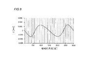
図7及び8に表されるように、ここで記述されたロータ1を備え付けるモータMは、実際は、磁束漏れが無く、そのコギングトルクカーブは、実質的に正弦関数であり、相対的に低い最大値を有する。
8極ロータを有するモータMは、図6に表されるように、好ましい距離R2、即ち、主軸D及び側部6を規定する弧11の中心との間の共通の距離は、弧11の頂点と主軸Dとの間の距離R1の約1/3に等しい。
各弧11は、約30°の角度Hの範囲を定め、そして、ロータ1は、換気穴28を有する。
As shown in FIGS. 7 and 8, the motor M equipped with the
As shown in FIG. 6, the motor M having an 8-pole rotor has a preferable distance R 2, that is, a common distance between the center of the
Each
好ましくは、代替実施形態において、距離R2、即ち、主軸D及び側部6を規定する弧11の中心との間の共通の距離は、弧11の頂点と主軸Dとの間の距離R1の約半分に等しい。
Preferably, in an alternative embodiment, the distance R2, ie the common distance between the main axis D and the center of the
本発明は、重要な利点を提供する。
配置手段20は、重量分散20がロータが静的から動的構成へ変化するとき実質的に変化しないので、ロータバランスを最適化することを保障する。
磁石の安定位置は、空隙を通した良好な磁束分散及びコギングトルクの有効な削減を成し遂げるために、ロータ位置を最適化することを可能にする。
The present invention provides significant advantages.
The placement means 20 ensures that the rotor balance is optimized because the
The stable position of the magnet allows the rotor position to be optimized to achieve good flux distribution through the air gap and effective reduction of cogging torque.
本発明は明白な産業上の適用性を有し、発明の範囲から逸脱することなく、様々な方法で改良され応用される。さらに、発明の詳細の全ては、技術的に等価な要素によって置換されても良い。
(態様1)
永久磁石(10)を含む電気モータのためのロータであって、
主軸(D)、
第1及び第2の末端壁(4、5)及び側面(6)によって囲まれた積層鉄心(2)、
モータ軸(8)に連結するための穴(7)、及び、
前記磁石(10)を収納するための複数の縦スロット(9)を有し、
前記ロータは、前記スロット(9)内に前記磁石(10)を固定するための位置決め装置(20)をさらに有することを特徴とするロータ。
(態様2)
前記位置決め装置(20)は、前記鉄心(2)と前記磁石(10)との間に弾性固定手段(17)を有することを特徴とする態様1に記載のロータ。
(態様3)
前記弾性固定手段(17)は、前記各磁石(10)とそれぞれのスロット(9)との間に位置決めされる少なくとも1つの弾性要素(18)を有することを特徴とする態様2に記載のロータ。
(態様4)
前記弾性要素(18)は、前記主軸(D)に対して半径方向に動作することを特徴とする態様3に記載のロータ。
(態様5)
前記鉄心(2)は、各弾性要素(18)のための溝(19)を有することを特徴とする態様3又は4に記載のロータ。
(態様6)
前記溝(19)は、前記第1及び第2の末端壁(4、5)の間に伸び、特に、前記主軸(D)に平行であることを特徴とする態様5に記載のロータ。
(態様7)
前記弾性要素(18)は、屈曲のスプリングから構成されることを特徴とする態様3〜6のいずれか一項に記載のロータ。
(態様8)
前記位置決め装置(20)は、前記スロット(9)内の前記磁石(10)を導くために、前記各スロット(9)の中にリブ(16)を有することを特徴とする態様1〜7のいずれか一項に記載のロータ。
(態様9)
前記リブ(16)は、約0.1〜0.5mmの間の長さの半径(R)の円形を有することを特徴とする態様8に記載のロータ。
(態様10)
前記半径(R)は、約0.2mmの長さであることを特徴とする態様9に記載のロータ。
(態様11)
前記第1及び第2の末端壁(4、5)の間に伸び、且つ、特に前記主軸(D)に平行であるバランス穴(21)を有することを特徴とする態様1〜10のいずれか一項に記載のロータ。
(態様12)
前記穴(21)の内部に配置されたバランス重し(22)を有することを特徴とする態様11に記載のロータ。
(態様13)
前記側面(6)は、前記縦スロット(9)の1つに各々が位置決めされた複数の接続弧(11)によって規定され、
前記弧(11)は、前記軸(D)から均等距離(R1)に配置された頂点(12)、及び、前記穴(7)の境界(24)内部に配置された中心を有し、かつ、
前記ロータは、特に4極ロータであることを特徴とする態様1〜12のいずれか一項に記載のロータ。
(態様14)
永久磁石(10)を含む電気モータのためのロータであって、
主軸(D)、
第1及び第2の末端壁(4、5)及び側面(6)によって囲まれた積層鉄心(2)、
モータ軸(8)に連結するための穴(7)、及び、
前記磁石(10)を収納するための複数の縦スロット(9)を有し、
前記側面(6)は、それぞれの頂点が前記軸(D)から等距離にあり且つ各頂点がそれぞれのスロット(9)にある複数の接続した弧(11)によって規定され、
前記ロータは、前記弧(11)の中心が前記穴(7)の境界(24)内部に位置決めされており、
前記ロータは、特に4極ロータであることを特徴とするロータ。
(態様15)
前記弧(11)は、約55°〜65°の角度(H)の範囲を定めることを特徴とする態様14に記載のロータ。
(態様16)
前記弧(11)は、約60°の角度(H)の範囲を定めることを特徴とする態様15に記載のロータ。
(態様17)
前記弧(11)は、長さ約12〜15mmの間の半径(R3)を有し、
前記磁石(10)は、約30〜50mmの長さ(L1)、約14〜16mmの幅(L2)、約2.5〜3.5mmの高さ(L3)であることを特徴とする態様14〜16のいずれか一項に記載のロータ。
(態様18)
前記弧(11)は、長さ約13.1mmの半径(R3)を有し、
前記磁石(10)は、具体的には、約40mmの長さ(L1)、約15.4mmの幅(L2)、及び約3mmの高さ(L3)であることを特徴とする態様17に記載のロータ。
(態様19)
前記弧(11)は、約55°〜65°の角度(H)の範囲を定めることを特徴とする態様14〜18のいずれか一項に記載のロータ。
(態様20)
前記弧(11)は、約60°の角度(H)の範囲を定めることを特徴とする態様19に記載のロータ。
(態様21)
前記側面(6)は、前記主軸(D)から均等距離(R1)に配置されたそれぞれの頂点(12)、及び、前記主軸(D)から均等距離(R2)の中心を有する複数の接続された弧(11)によって規定され、
前記距離(R2)は、前記距離(R1)の約1/3に等しく、
前記ロータは、特に8極ロータであり、
前記磁石(10)は、前記弧(11)に位置決めされることを特徴とする態様1〜12のいずれか一項に記載のロータ。
(態様22)
前記弧(11)は、約25°〜35°の角度(H)の範囲を定めることを特徴とする態様21に記載のロータ。
(態様23)
前記弧(11)は、約30°の角度(H)の範囲を定めることを特徴とする態様22に記載のロータ。
(態様24)
前記側面(6)は、前記主軸(D)から均等距離(R1)に配置されたそれぞれの頂点(12)、及び、前記主軸(D)から均等距離(R2)の中心を有する複数の接続された弧(11)によって規定され、
前記距離(R2)は、前記距離(R1)の約半分に等しく、
前記ロータは、特に8極ロータであり、
前記磁石(10)は、前記弧(11)に位置決めされることを特徴とする態様1〜12のいずれか一項に記載のロータ。
(態様25)
前記磁石(10)は、前記それぞれのスロットの中で並んで収容される複数の部分(10a、10b、10c、10d)から構成されることを特徴とする態様1〜24のいずれか一項に記載のロータ。
(態様26)
前記磁石(10)の各々は、規定の重量を有することを特徴とする態様1〜25のいずれか一項に記載のロータ。
(態様27)
前記第1及び第2の末端壁(4、5)は、互いに平行であり、
前記積層鉄心(2)は、前記主軸(D)について互いに対して少なくとも部分的に回転している複数の積層(3)を有することを特徴とする態様1〜26のいずれか一項に記載のロータ。
The present invention has obvious industrial applicability and can be improved and applied in various ways without departing from the scope of the invention. Moreover, all of the details of the invention may be replaced by technically equivalent elements.
(Aspect 1)
A rotor for an electric motor including a permanent magnet (10),
Spindle (D),
A laminated core (2) surrounded by first and second end walls (4, 5) and side faces (6);
A hole (7) for connection to the motor shaft (8), and
A plurality of vertical slots (9) for accommodating the magnets (10);
The rotor further comprises a positioning device (20) for fixing the magnet (10) in the slot (9).
(Aspect 2)
The rotor according to
(Aspect 3)
Rotor according to aspect 2, characterized in that the elastic fixing means (17) comprises at least one elastic element (18) positioned between each magnet (10) and a respective slot (9). .
(Aspect 4)
The rotor according to
(Aspect 5)
The rotor according to
(Aspect 6)
Rotor according to
(Aspect 7)
The rotor according to any one of
(Aspect 8)
The positioning device (20) has a rib (16) in each slot (9) for guiding the magnet (10) in the slot (9). The rotor according to any one of the above.
(Aspect 9)
The rotor of
(Aspect 10)
The rotor according to
(Aspect 11)
Any one of
(Aspect 12)
Rotor according to
(Aspect 13)
The side surface (6) is defined by a plurality of connecting arcs (11) each positioned in one of the longitudinal slots (9);
The arc (11) has a vertex (12) disposed at an equal distance (R1) from the axis (D) and a center disposed within the boundary (24) of the hole (7); and ,
The rotor according to any one of
(Aspect 14)
A rotor for an electric motor including a permanent magnet (10),
Spindle (D),
A laminated core (2) surrounded by first and second end walls (4, 5) and side faces (6);
A hole (7) for connection to the motor shaft (8), and
A plurality of vertical slots (9) for accommodating the magnets (10);
The side surface (6) is defined by a plurality of connected arcs (11), each vertex being equidistant from the axis (D) and each vertex being in a respective slot (9),
The rotor has a center of the arc (11) positioned within the boundary (24) of the hole (7),
The rotor is a quadrupole rotor, in particular.
(Aspect 15)
15. The rotor of
(Aspect 16)
16. The rotor of
(Aspect 17)
Said arc (11) has a radius (R3) between about 12-15 mm in length;
The magnet (10) has a length (L1) of about 30-50 mm, a width (L2) of about 14-16 mm, and a height (L3) of about 2.5-3.5 mm. The rotor according to any one of 14 to 16.
(Aspect 18)
The arc (11) has a radius (R3) of about 13.1 mm in length;
Specifically, the magnet (10) has a length (L1) of about 40 mm, a width (L2) of about 15.4 mm, and a height (L3) of about 3 mm. The described rotor.
(Aspect 19)
19. A rotor according to any one of
(Aspect 20)
A rotor according to
(Aspect 21)
The side surface (6) is connected to a plurality of vertices (12) arranged at an equal distance (R1) from the main axis (D) and a center at an equal distance (R2) from the main axis (D). Defined by the arc (11)
The distance (R2) is equal to about 1/3 of the distance (R1);
Said rotor is in particular an 8-pole rotor,
The rotor according to any one of
(Aspect 22)
A rotor according to
(Aspect 23)
25. A rotor according to
(Aspect 24)
The side surface (6) is connected to a plurality of vertices (12) arranged at an equal distance (R1) from the main axis (D) and a center at an equal distance (R2) from the main axis (D). Defined by the arc (11)
The distance (R2) is equal to about half of the distance (R1);
Said rotor is in particular an 8-pole rotor,
The rotor according to any one of
(Aspect 25)
The magnet (10) is composed of a plurality of portions (10a, 10b, 10c, 10d) accommodated side by side in the respective slots. The described rotor.
(Aspect 26)
26. A rotor according to any one of
(Aspect 27)
The first and second end walls (4, 5) are parallel to each other;
27. The laminated core (2) according to any one of
Claims (18)
主軸(D)、
第1及び第2の末端壁(4、5)及び側面(6)によって囲まれた積層鉄心(2)、
モータ軸(8)に連結するための穴(7)、及び、
前記磁石(10)を収納するための複数の縦スロット(9)を有し、
前記ロータは、前記スロット(9)内の前記磁石(10)を導くために、前記各スロット(9)の中に提供されるガイドリブ(16)をさらに有し、
各スロット(9)は、前記スロット(9)の向かい合う端にそれぞれ二つの末端部(15)を有し、
各末端部(15)は、前記スロット(9)から前記ガイドリブ(16)の一つを越えて外側に伸び、
前記側面(6)は、複数の直線部分(13)を含み、
各直線部分(13)は、隣接するスロット(9)の隣接する末端部(15)の半径方向の外側に位置され、
隣接するスロット(9)の隣接する末端部(15)の半径方向の内側のエッジ及び半径方向の外側のエッジは、それぞれ、互いに向かってまっすぐに伸び、
前記隣接する末端部(15)の半径方向の内側のエッジ及び半径方向の外側のエッジの両方は、互いに平行であり、且つ前記側面(6)の隣接する直線部分(13)とも平行であり、
前記ロータは、前記スロット(9)内に前記磁石(10)を固定するための、前記各磁石(10)とそれぞれのスロット(9)との間に位置決めされる屈曲のスプリング(18)をさらに有し、
前記鉄心(2)は、前記第1及び第2の末端壁(4、5)の間に、前記主軸(D)に対して平行な方向に伸びる、各前記屈曲のスプリング(18)のための溝(19)を有し、
各前記スプリング(18)は、前記溝(19)の中に縦に挿入され、
各前記溝(19)は、それぞれの前記スロット(9)にそって半分の位置に配置され、 前記側面(6)は、各々が前記縦スロット(9)の1つに位置決めされ、且つ二つの直線部分(13)に接続する複数の接続弧(11)によって規定され、
前記弧(11)は、前記主軸(D)から均等距離(R1)に配置された頂点(12)、及び、前記穴(7)の境界(24)内部に配置された中心を有することを特徴とするロータ。 A rotor for an electric motor including a permanent magnet (10),
Spindle (D),
A laminated core (2) surrounded by first and second end walls (4, 5) and side faces (6);
A hole (7) for connection to the motor shaft (8), and
A plurality of vertical slots (9) for accommodating the magnets (10);
The rotor further comprises a guide rib (16) provided in each slot (9) to guide the magnet (10) in the slot (9);
Each slot (9) has two end portions (15) at opposite ends of the slot (9),
Each end (15) extends outwardly from the slot (9) beyond one of the guide ribs (16),
The side surface (6) includes a plurality of straight portions (13),
Each straight portion (13) is located radially outward of an adjacent end (15) of an adjacent slot (9);
The radially inner edge and the radially outer edge of the adjacent end (15) of the adjacent slot (9) each extend straight toward each other,
Both the radially inner edge and the radially outer edge of the adjacent end (15) are parallel to each other and also to the adjacent straight portion (13) of the side surface (6);
The rotor further comprises a bent spring (18) positioned between each magnet (10) and the respective slot (9) for securing the magnet (10) in the slot (9). Have
The iron core (2) extends between the first and second end walls (4, 5) in a direction parallel to the main axis (D) for each bending spring (18). Having a groove (19),
Each spring (18) is inserted vertically into the groove (19),
Each said groove (19) is arranged in half position along each said slot (9), said side surface (6) is positioned in one of said longitudinal slots (9) and two Defined by a plurality of connecting arcs (11) connecting to the straight section (13),
The arc (11) has a vertex (12) disposed at an equal distance (R1) from the main axis (D) and a center disposed within the boundary (24) of the hole (7). Rotor.
前記磁石(10)は、30〜50mmの長さ(L1)、14〜16mmの幅(L2)、2.5〜3.5mmの高さ(L3)であることを特徴とする請求項7〜9のいずれか一項に記載のロータ。 Said arc (11) has a radius (R3) between 12-15 mm in length;
Said magnet (10) has a length of 30 to 50 mm (L1), the width of 14~16Mm (L2), claim, characterized in that the height of 2.5 to 3.5 mm (L3). 7 to The rotor according to claim 9 .
前記磁石(10)は、40mmの長さ(L1)、15.4mmの幅(L2)、及び3mmの高さ(L3)であることを特徴とする請求項10に記載のロータ。 Said arc (11) has a radius (R3) of length 13.1 mm;
11. The rotor according to claim 10 , wherein the magnet (10) has a length (L1) of 40 mm, a width (L2) of 15.4 mm, and a height (L3) of 3 mm.
前記距離(R2)は、前記距離(R1)の1/3に等しく、
前記ロータは、8極ロータであり、
前記磁石(10)は、前記弧(11)に位置決めされることを特徴とする請求項1〜6のいずれか一項に記載のロータ。 The plurality of connected arcs (11) have respective vertices (12) arranged at an equal distance (R1) from the main axis (D), and an equal distance (R2) from the main axis (D). have a respective center,
The distance (R2) is equal to 1/3 of the distance (R1),
The rotor is an 8-pole rotor;
The rotor according to any one of claims 1 to 6 , wherein the magnet (10) is positioned on the arc (11).
前記距離(R2)は、前記距離(R1)の半分に等しく、
前記ロータは、8極ロータであり、
前記磁石(10)は、前記弧(11)に位置決めされることを特徴とする請求項1〜6のいずれか一項に記載のロータ。 The plurality of connected arcs (11) have respective vertices (12) arranged at an equal distance (R1) from the main axis (D), and an equal distance (R2) from the main axis (D). have a respective center,
The distance (R2) is equal to half of the distance (R1),
The rotor is an 8-pole rotor;
The rotor according to any one of claims 1 to 6 , wherein the magnet (10) is positioned on the arc (11).
前記積層鉄心(2)は、前記主軸(D)について互いに対して少なくとも部分的に回転している複数の積層(3)を有することを特徴とする請求項1〜17のいずれか一項に記載のロータ。 The first and second end walls (4, 5) are parallel to each other;
Said laminated core (2) is claimed in any one of claims 1 to 17, characterized in that at least partially rotated to a plurality are stacked (3) relative to each other about the main axis (D) Rotor.
Applications Claiming Priority (3)
| Application Number | Priority Date | Filing Date | Title |
|---|---|---|---|
| IT000437A ITBO20050437A1 (en) | 2005-06-30 | 2005-06-30 | ROTOR FOR ELECTRIC MACHINE |
| ITBO2005A000437 | 2005-06-30 | ||
| PCT/IB2006/001764 WO2007004009A2 (en) | 2005-06-30 | 2006-06-28 | A rotor for an electrical machine |
Publications (3)
| Publication Number | Publication Date |
|---|---|
| JP2008545364A JP2008545364A (en) | 2008-12-11 |
| JP2008545364A5 JP2008545364A5 (en) | 2009-07-30 |
| JP5420900B2 true JP5420900B2 (en) | 2014-02-19 |
Family
ID=37084858
Family Applications (1)
| Application Number | Title | Priority Date | Filing Date |
|---|---|---|---|
| JP2008519001A Expired - Fee Related JP5420900B2 (en) | 2005-06-30 | 2006-06-28 | Rotor for electric machine |
Country Status (14)
| Country | Link |
|---|---|
| US (1) | US8405269B2 (en) |
| EP (1) | EP1905145A2 (en) |
| JP (1) | JP5420900B2 (en) |
| KR (1) | KR101229527B1 (en) |
| CN (1) | CN101213720B (en) |
| AU (1) | AU2006264597B2 (en) |
| BR (1) | BRPI0611843A2 (en) |
| CA (1) | CA2612157C (en) |
| IL (1) | IL188057A0 (en) |
| IT (1) | ITBO20050437A1 (en) |
| MX (1) | MX2007016535A (en) |
| RU (2) | RU2007147457A (en) |
| WO (1) | WO2007004009A2 (en) |
| ZA (1) | ZA200711064B (en) |
Families Citing this family (72)
| Publication number | Priority date | Publication date | Assignee | Title |
|---|---|---|---|---|
| DE102007015249A1 (en) | 2007-03-27 | 2008-10-02 | Miele & Cie. Kg | Rotor, in particular for an electric motor of a circulating pump |
| DE102007029157A1 (en) * | 2007-06-25 | 2009-01-08 | Robert Bosch Gmbh | Synchronous motor with 12 stator teeth and 10 rotor poles |
| KR101478838B1 (en) * | 2008-01-22 | 2015-01-05 | 엘지전자 주식회사 | Fan motor, BLDC motor and rotator for the same |
| DE102008018724A1 (en) * | 2008-04-14 | 2009-10-22 | Siemens Aktiengesellschaft | Secondary part i.e. rotor, for e.g. two-pole synchronous motor, has positioning elements e.g. steel tape, for positioning permanent magnets in magnet bags, and magnet bags with recesses for accommodation of positioning elements |
| EP2321667B1 (en) | 2008-08-07 | 2019-12-18 | Koninklijke Philips N.V. | Scintillating material |
| JP5190318B2 (en) * | 2008-09-02 | 2013-04-24 | 株式会社三井ハイテック | Permanent magnet type laminated iron core and manufacturing method thereof |
| DE102008043138A1 (en) * | 2008-10-23 | 2010-04-29 | Robert Bosch Gmbh | Slat package of a rotor of an electric machine |
| EP2249460B1 (en) | 2009-05-05 | 2012-03-07 | Iro Ab | Positioning substrate and permanent magnet rotor |
| DE102009025622A1 (en) | 2009-06-17 | 2010-12-23 | Miele & Cie. Kg | Rotor for electric motor, particularly of circulation pump, has rotor packet, which is mounted on shaft, where multiple rotating bags are formed on rotor packet, in which magnet is inserted in each case |
| JP2011015499A (en) * | 2009-06-30 | 2011-01-20 | Sanyo Electric Co Ltd | Rotor of electric motor |
| JP2011015500A (en) * | 2009-06-30 | 2011-01-20 | Sanyo Electric Co Ltd | Rotor of electric motor |
| US8564168B2 (en) * | 2010-05-24 | 2013-10-22 | Remy Technologies, L.L.C. | Rotor lamination assembly |
| FR2963175A1 (en) * | 2010-07-22 | 2012-01-27 | Ssd Parvex Sas | Rotor for synchronous motor, has elastic element exerting restoring force of magnets toward predetermined position in housing, where elastic element is support on face of magnets and housings |
| DE102010039334A1 (en) * | 2010-08-16 | 2012-02-16 | Robert Bosch Gmbh | Attaching magnets to a rotor |
| DE202010017376U1 (en) * | 2010-08-16 | 2014-01-08 | Robert Bosch Gmbh | Attaching magnets to a rotor |
| JP5418467B2 (en) | 2010-11-02 | 2014-02-19 | 株式会社安川電機 | Rotating electric machine |
| JP2012120326A (en) * | 2010-11-30 | 2012-06-21 | Fujitsu General Ltd | Interior magnet rotor, motor, and method for assembling motor |
| DE102011080671A1 (en) * | 2011-08-09 | 2013-02-14 | Siemens Aktiengesellschaft | Rotor for a permanent magnetic machine |
| ITBO20110587A1 (en) * | 2011-10-17 | 2013-04-18 | Spal Automotive Srl | ROTOR FOR ELECTRIC MACHINE AND ITS ASSEMBLY PROCEDURE |
| FR2993506B1 (en) * | 2012-07-19 | 2015-06-05 | Leroy Somer Moteurs | ASSEMBLY COMPRISING A GENERATOR AND ELECTRIC MOTORS FOR AN AIR CONDITIONING OR REFRIGERATION SYSTEM FOR A VEHICLE. |
| CN103580324B (en) * | 2012-08-01 | 2017-09-01 | 德昌电机(深圳)有限公司 | P-m rotor and the permanent magnet motor with the rotor |
| DE102012016927A1 (en) * | 2012-08-27 | 2014-02-27 | Volkswagen Aktiengesellschaft | Rotor of electric machine e.g. electric motor, has clamping element that is extended along extending direction of permanent magnet in recess such that permanent magnet is partially enclosed by clamping element |
| JP2014054154A (en) * | 2012-09-10 | 2014-03-20 | Nsk Ltd | Electric motor and electric power steering device |
| JP2014054153A (en) * | 2012-09-10 | 2014-03-20 | Nsk Ltd | Electric motor and electric power steering device |
| DE102012218716A1 (en) * | 2012-10-15 | 2014-04-17 | Continental Automotive Gmbh | Rotor arrangement for an electric machine and method for producing a rotor assembly |
| JP5596103B2 (en) * | 2012-10-31 | 2014-09-24 | ファナック株式会社 | Motor rotor using magnets |
| US9641033B2 (en) | 2013-09-06 | 2017-05-02 | General Electric Company | Electric machine having offset rotor sections |
| US9906108B2 (en) | 2012-11-01 | 2018-02-27 | General Electric Company | Sensorless electric machine |
| US9941775B2 (en) | 2012-11-01 | 2018-04-10 | General Electric Company | D-ring implementation in skewed rotor assembly |
| US9871418B2 (en) | 2012-11-01 | 2018-01-16 | General Electric Company | Sensorless electric machine |
| JP2014107924A (en) * | 2012-11-27 | 2014-06-09 | Tamagawa Seiki Co Ltd | Ipm rotor structure |
| EP2740966B1 (en) * | 2012-12-05 | 2020-02-05 | Siemens Aktiengesellschaft | Method for balancing a component |
| JP5787190B2 (en) * | 2012-12-10 | 2015-09-30 | 株式会社デンソー | Rotor and rotating electric machine using the same |
| US9148055B2 (en) | 2013-03-15 | 2015-09-29 | Cooper Technologies Company | Power system with electronic impedance switch controls and methods for supplying power to a load |
| DE102013206438A1 (en) | 2013-04-11 | 2014-10-16 | Bühler Motor GmbH | Permanent magnet rotor for an electronically commutated DC motor |
| JP2014212599A (en) * | 2013-04-17 | 2014-11-13 | 日本電産テクノモータ株式会社 | Synchronous induction motor |
| ITBS20130104A1 (en) * | 2013-07-17 | 2015-01-18 | I M E S P A Ind Motori El Ettrici | ENGINE GROUP |
| US20150022044A1 (en) * | 2013-07-22 | 2015-01-22 | Steering Solutions Ip Holding Corporation | System and method for reducing torque ripple in an interior permanent magnet motor |
| US9287742B2 (en) | 2013-08-05 | 2016-03-15 | General Electric Company | Spoke permanent magnet machine with reduced torque ripple and method of manufacturing thereof |
| JP5954279B2 (en) * | 2013-08-28 | 2016-07-20 | 株式会社安川電機 | Rotating electric machine |
| US9906082B2 (en) | 2013-09-06 | 2018-02-27 | General Electric Company | Electric machine having reduced torque oscillations and axial thrust |
| WO2015051571A1 (en) * | 2013-10-11 | 2015-04-16 | 睿能机电有限公司 | Magnetic circuit structure of dc brushless motor and permanent magnet embedded rotor thereof |
| TWI508414B (en) * | 2013-11-12 | 2015-11-11 | Hon Hai Prec Ind Co Ltd | Rotor and motor using the same |
| CN104682650A (en) * | 2013-11-28 | 2015-06-03 | 德昌电机(深圳)有限公司 | Motor rotor and brushless motor with motor rotor |
| US10491088B2 (en) * | 2014-02-20 | 2019-11-26 | Mitsubishi Electric Corporation | Permanent magnet motor with a rotor having press fitted rivets and press fitted shaft and pin holes and a method for manufacturing the rotor |
| CN106165256B (en) * | 2014-03-24 | 2018-10-19 | 日立汽车系统株式会社 | Permanent magnet rotary electric machine and its manufacturing method |
| DE112015001725T5 (en) * | 2014-04-08 | 2017-01-05 | Mitsubishi Electric Corporation | Rotating electrical machine with embedded permanent magnets |
| WO2016015289A1 (en) * | 2014-07-31 | 2016-02-04 | 广东威灵电机制造有限公司 | Motor rotor and motor having same |
| FR3032839B1 (en) * | 2015-02-16 | 2018-05-04 | Alstom Transport Technologies | ELECTRIC MOTOR ROTOR AND CORRESPONDING ELECTRIC MOTOR |
| FR3033959B1 (en) * | 2015-03-16 | 2018-04-13 | Valeo Equipements Electriques Moteur | ROTOR OF ROTATING ELECTRIC MACHINE WITH CONFIGURATION OF PERMANENT MAGNETS OPTIMIZED |
| FR3033960B1 (en) * | 2015-03-16 | 2018-03-30 | Valeo Equipements Electriques Moteur | ROTOR OF ROTATING ELECTRIC MACHINE WITH IMPLANTATION OF OPTIMIZED MOUNTING MEANS |
| FR3033958B1 (en) * | 2015-03-16 | 2018-04-13 | Valeo Equipements Electriques Moteur | PERMANENT MAGNET ROTATING ELECTRIC MACHINE ROTOR |
| CN106160284A (en) * | 2015-04-10 | 2016-11-23 | 睿能机电有限公司 | A kind of p-m rotor |
| CN104767308A (en) * | 2015-05-05 | 2015-07-08 | 湖北立锐机电有限公司 | Dynamic balancing structure for permanent magnet synchronous motor rotor |
| FR3036006B1 (en) * | 2015-05-07 | 2019-08-02 | Valeo Equipements Electriques Moteur | ROTOR OF ROTATING ELECTRIC MACHINE PROVIDED WITH AT LEAST ONE FOLDING MEMBER OF A MAGNET WITHIN A CORRESPONDING CAVITY |
| DE102016109083A1 (en) * | 2015-05-21 | 2016-11-24 | Johnson Electric S.A. | Single-phase brushless motor and electrical appliance |
| US10720808B2 (en) * | 2015-11-23 | 2020-07-21 | Ingersoll-Rand Industrial U.S., Inc. | Method of making a permanent magnet rotor |
| CN106972653A (en) * | 2016-01-14 | 2017-07-21 | 德昌电机(深圳)有限公司 | Motor and its outer magnetic core, inner magnetic core |
| JP6143314B1 (en) * | 2016-07-29 | 2017-06-07 | パナソニック アプライアンシズ リフリジレーション デヴァイシズ シンガポール | Hermetic refrigerant compressor and refrigeration system |
| JP2018026965A (en) * | 2016-08-10 | 2018-02-15 | 富士電機株式会社 | Rotor and permanent magnet type rotary electric machine |
| FR3055484B1 (en) * | 2016-08-31 | 2018-08-10 | Valeo Equipements Electriques Moteur | ROTOR OF ROTATING ELECTRIC MACHINE WITH AT LEAST ONE CURVED PORTION OF RECEIVING A SPRING |
| DE102017103619A1 (en) * | 2017-02-22 | 2018-08-23 | Ebm-Papst St. Georgen Gmbh & Co. Kg | Electric motor, inner rotor and rotor plate |
| GB2569142B (en) * | 2017-12-06 | 2023-05-03 | Trw Ltd | An interior permanent magnet motor |
| CN109980806A (en) * | 2017-12-28 | 2019-07-05 | 丹佛斯(天津)有限公司 | Rotor and motor |
| WO2019169828A1 (en) * | 2018-03-07 | 2019-09-12 | 广东美的生活电器制造有限公司 | Food processor and electric motor for food processor |
| JP7055220B2 (en) | 2018-11-27 | 2022-04-15 | 三菱電機株式会社 | Rotating electric machine |
| JP7024745B2 (en) * | 2019-02-15 | 2022-02-24 | 株式会社デンソー | Embedded magnet type rotor |
| CN112152348B (en) * | 2019-06-27 | 2022-01-04 | 台达电子工业股份有限公司 | Rotor lamination and rotor assembly suitable for same |
| DE102019124710A1 (en) * | 2019-09-13 | 2021-03-18 | Metabowerke Gmbh | Rotor sheet for a rotor of an electric motor, rotor for an electric motor and electric motor |
| DE102020215316A1 (en) * | 2020-12-03 | 2022-06-09 | Valeo Siemens Eautomotive Germany Gmbh | Rotor of an electrical machine |
| FR3121799B1 (en) * | 2021-04-08 | 2023-03-03 | Seb Sa | ROTOR FOR BRUSHLESS SYNCHRONOUS MOTOR WITH INSERTED PERMANENT MAGNETS |
| CN116488372A (en) * | 2021-12-08 | 2023-07-25 | 安徽威灵汽车部件有限公司 | Rotor punching sheet, rotor, motor, electric power steering system and vehicle |
Family Cites Families (38)
| Publication number | Priority date | Publication date | Assignee | Title |
|---|---|---|---|---|
| US3445700A (en) * | 1967-01-09 | 1969-05-20 | Georator Corp | Dynamo-electric machine |
| DE69128083T2 (en) * | 1990-07-12 | 1998-03-19 | Seiko Epson Corp | BRUSHLESS MOTOR RUNNER AND MANUFACTURE THEREOF |
| JPH0583892A (en) * | 1991-09-19 | 1993-04-02 | Seiko Epson Corp | Permanent magnet rotor |
| JPH05219668A (en) * | 1992-02-03 | 1993-08-27 | Toshiba Corp | Permanent magnet type rotor |
| US5679995A (en) * | 1992-08-12 | 1997-10-21 | Seiko Epson Corporation | Permanent magnet rotor of brushless motor |
| JPH06133479A (en) * | 1992-09-02 | 1994-05-13 | Toshiba Corp | Permanent magnet rotor and manufacture thereof |
| JPH0984285A (en) * | 1995-09-13 | 1997-03-28 | Aichi Emerson Electric Co Ltd | Magnet rotor |
| JP3654377B2 (en) * | 1995-12-11 | 2005-06-02 | 株式会社安川電機 | Inner magnet type synchronous motor |
| JPH09182332A (en) * | 1995-12-21 | 1997-07-11 | Daikin Ind Ltd | Dc brushless motor |
| CN1071061C (en) * | 1996-02-23 | 2001-09-12 | 松下电器产业株式会社 | Motor |
| JPH09327140A (en) * | 1996-06-07 | 1997-12-16 | Hitachi Ltd | Electric rotating machine of permanent magnet rotation type and its manufacture |
| US5801470A (en) * | 1996-12-19 | 1998-09-01 | General Electric Company | Rotors with retaining cylinders and reduced harmonic field effect losses |
| JPH11289699A (en) * | 1998-04-06 | 1999-10-19 | Matsushita Electric Ind Co Ltd | Rotor of electric motor |
| JPH11355985A (en) * | 1998-06-04 | 1999-12-24 | Toshiba Corp | Permanent magnet type motor |
| JP2000197292A (en) * | 1998-10-21 | 2000-07-14 | Mitsubishi Electric Corp | Permanent-magnet rotor of permanent-magnet mounted motor |
| JP4089072B2 (en) * | 1998-10-23 | 2008-05-21 | 三菱電機株式会社 | Permanent magnet embedded motor |
| JP2000175388A (en) * | 1998-12-02 | 2000-06-23 | Meidensha Corp | Permanent magnet burial type motor |
| DE69928363T2 (en) * | 1998-12-25 | 2006-06-01 | Matsushita Electric Industrial Co., Ltd., Kadoma | Motor with embedded permanent magnets embedded in the rotor |
| JP2000341920A (en) * | 1999-05-26 | 2000-12-08 | Meidensha Corp | Permanent magnet embedded motor |
| JP2001025191A (en) * | 1999-07-05 | 2001-01-26 | Nissan Motor Co Ltd | Rotor of motor and manufacture thereof |
| JP2001069701A (en) * | 1999-08-30 | 2001-03-16 | Mitsubishi Heavy Ind Ltd | Magnet motor |
| JP4363746B2 (en) * | 2000-05-25 | 2009-11-11 | 株式会社東芝 | Permanent magnet type reluctance type rotating electrical machine |
| DE10056036A1 (en) | 2000-11-11 | 2002-05-29 | Bosch Gmbh Robert | anchor |
| JP3887541B2 (en) * | 2001-02-16 | 2007-02-28 | 三菱電機株式会社 | Embedded magnet rotor |
| JP2002354727A (en) * | 2001-05-21 | 2002-12-06 | Hitachi Ltd | Rotor with buried permanent magnet and electric rotating machine |
| JP3778271B2 (en) * | 2001-06-06 | 2006-05-24 | 株式会社荏原製作所 | Permanent magnet type motor |
| US6867526B2 (en) * | 2001-09-05 | 2005-03-15 | Koyo Seiko Co., Ltd. | Brushless DC motor |
| TW577658U (en) * | 2001-09-10 | 2004-02-21 | Adlee Powertronic Co Ltd | Rotor structure for a motor having built-in type permanebt magnet |
| ATE311030T1 (en) * | 2002-03-22 | 2005-12-15 | Ebm Papst St Georgen Gmbh & Co | INNER ROTOR MOTOR |
| JP3621929B2 (en) * | 2002-04-18 | 2005-02-23 | ファナック株式会社 | Electric motor and manufacturing method thereof |
| US20040217666A1 (en) * | 2002-12-11 | 2004-11-04 | Ballard Power Systems Corporation | Rotor assembly of synchronous machine |
| CN100426627C (en) * | 2003-01-15 | 2008-10-15 | 三菱电机株式会社 | Permanent magnet type motor |
| JP3852930B2 (en) * | 2003-02-27 | 2006-12-06 | アイチエレック株式会社 | Permanent magnet rotating machine |
| EP1458077A1 (en) * | 2003-03-12 | 2004-09-15 | ebm-papst St. Georgen GmbH & Co. KG | Multi-phase electric motor with rotor having embedded permanent magnets |
| JP2004289904A (en) * | 2003-03-20 | 2004-10-14 | Isuzu Motors Ltd | Permanent magnet retaining structure for rotor |
| US7042127B2 (en) * | 2003-04-02 | 2006-05-09 | Nidec Sankyo Corporation | Permanent magnet embedded motor |
| JP2004357418A (en) | 2003-05-29 | 2004-12-16 | Honda Motor Co Ltd | Permanent magnet fixing structure in rotor for rotating electric machine |
| JP4351482B2 (en) * | 2003-06-23 | 2009-10-28 | 本田技研工業株式会社 | Embedded magnet rotor and manufacturing method of embedded magnet rotor |
-
2005
- 2005-06-30 IT IT000437A patent/ITBO20050437A1/en unknown
-
2006
- 2006-06-28 MX MX2007016535A patent/MX2007016535A/en active IP Right Grant
- 2006-06-28 BR BRPI0611843-7A patent/BRPI0611843A2/en active Search and Examination
- 2006-06-28 CN CN2006800240899A patent/CN101213720B/en not_active Expired - Fee Related
- 2006-06-28 US US11/922,910 patent/US8405269B2/en not_active Expired - Fee Related
- 2006-06-28 KR KR1020087002572A patent/KR101229527B1/en not_active IP Right Cessation
- 2006-06-28 EP EP06779782A patent/EP1905145A2/en not_active Withdrawn
- 2006-06-28 AU AU2006264597A patent/AU2006264597B2/en not_active Ceased
- 2006-06-28 JP JP2008519001A patent/JP5420900B2/en not_active Expired - Fee Related
- 2006-06-28 WO PCT/IB2006/001764 patent/WO2007004009A2/en active Application Filing
- 2006-06-28 RU RU2007147457/09A patent/RU2007147457A/en unknown
- 2006-06-28 CA CA2612157A patent/CA2612157C/en not_active Expired - Fee Related
- 2006-06-28 ZA ZA200711064A patent/ZA200711064B/en unknown
-
2007
- 2007-12-11 IL IL188057A patent/IL188057A0/en not_active IP Right Cessation
-
2012
- 2012-01-16 RU RU2012101459/07U patent/RU119541U1/en active
Also Published As
| Publication number | Publication date |
|---|---|
| AU2006264597A1 (en) | 2007-01-11 |
| AU2006264597B2 (en) | 2010-11-25 |
| CA2612157C (en) | 2015-11-24 |
| RU119541U1 (en) | 2012-08-20 |
| MX2007016535A (en) | 2008-03-06 |
| US8405269B2 (en) | 2013-03-26 |
| KR101229527B1 (en) | 2013-02-04 |
| CN101213720A (en) | 2008-07-02 |
| EP1905145A2 (en) | 2008-04-02 |
| CN101213720B (en) | 2012-06-20 |
| IL188057A0 (en) | 2008-03-20 |
| CA2612157A1 (en) | 2007-01-11 |
| WO2007004009A3 (en) | 2007-04-26 |
| RU2007147457A (en) | 2009-06-27 |
| WO2007004009A2 (en) | 2007-01-11 |
| BRPI0611843A2 (en) | 2011-12-20 |
| ZA200711064B (en) | 2009-04-29 |
| KR20080035593A (en) | 2008-04-23 |
| JP2008545364A (en) | 2008-12-11 |
| ITBO20050437A1 (en) | 2007-01-01 |
| US20090115279A1 (en) | 2009-05-07 |
Similar Documents
| Publication | Publication Date | Title |
|---|---|---|
| JP5420900B2 (en) | Rotor for electric machine | |
| EP1414130B1 (en) | Electric motor with a permanent magnet rotor | |
| US10110076B2 (en) | Single-phase brushless motor | |
| US9018816B2 (en) | Rotor of motor having interpole magnets in holding member | |
| JP2008545364A5 (en) | ||
| EP3101788A1 (en) | Single-phase outer-rotor motor and electric apparatus having the same | |
| JP2010098929A (en) | Double gap motor | |
| JP5969290B2 (en) | Rotor and motor | |
| CN102629786A (en) | Rotating electrical machine | |
| US20170149318A1 (en) | Single Phase Permanent Magnet Brushless Motor | |
| JP6074887B2 (en) | Gap gauge used for assembling electric motor and method for manufacturing electric motor | |
| KR20190074467A (en) | A Motor having split stator | |
| KR101597967B1 (en) | Stator of Plate type motor and Plate type motor using the same | |
| KR101221251B1 (en) | Rotor of interior permanent magnet motor | |
| KR101448647B1 (en) | Motor | |
| JP6468118B2 (en) | motor | |
| KR101405973B1 (en) | Motor | |
| WO2022181035A1 (en) | Motor | |
| KR20100109693A (en) | Inteior permanent magnet type motor | |
| KR20230000836A (en) | Rotor | |
| JP6662008B2 (en) | Stator, motor, and stator manufacturing method | |
| CN113394938A (en) | Electric machine with radially embedded permanent magnet rotor and method therefor | |
| JP5840919B2 (en) | Rotor and motor | |
| JP2020174492A (en) | motor | |
| KR20100005896A (en) | Motor |
Legal Events
| Date | Code | Title | Description |
|---|---|---|---|
| A521 | Request for written amendment filed |
Free format text: JAPANESE INTERMEDIATE CODE: A523 Effective date: 20090611 |
|
| A621 | Written request for application examination |
Free format text: JAPANESE INTERMEDIATE CODE: A621 Effective date: 20090611 |
|
| A131 | Notification of reasons for refusal |
Free format text: JAPANESE INTERMEDIATE CODE: A131 Effective date: 20111101 |
|
| A601 | Written request for extension of time |
Free format text: JAPANESE INTERMEDIATE CODE: A601 Effective date: 20120131 |
|
| A602 | Written permission of extension of time |
Free format text: JAPANESE INTERMEDIATE CODE: A602 Effective date: 20120207 |
|
| A521 | Request for written amendment filed |
Free format text: JAPANESE INTERMEDIATE CODE: A523 Effective date: 20120420 |
|
| A131 | Notification of reasons for refusal |
Free format text: JAPANESE INTERMEDIATE CODE: A131 Effective date: 20121204 |
|
| A601 | Written request for extension of time |
Free format text: JAPANESE INTERMEDIATE CODE: A601 Effective date: 20130301 |
|
| A602 | Written permission of extension of time |
Free format text: JAPANESE INTERMEDIATE CODE: A602 Effective date: 20130308 |
|
| A521 | Request for written amendment filed |
Free format text: JAPANESE INTERMEDIATE CODE: A523 Effective date: 20130425 |
|
| A01 | Written decision to grant a patent or to grant a registration (utility model) |
Free format text: JAPANESE INTERMEDIATE CODE: A01 Effective date: 20131022 |
|
| A61 | First payment of annual fees (during grant procedure) |
Free format text: JAPANESE INTERMEDIATE CODE: A61 Effective date: 20131121 |
|
| R250 | Receipt of annual fees |
Free format text: JAPANESE INTERMEDIATE CODE: R250 |
|
| R250 | Receipt of annual fees |
Free format text: JAPANESE INTERMEDIATE CODE: R250 |
|
| LAPS | Cancellation because of no payment of annual fees |