JP5420342B2 - Electric tool - Google Patents
Electric tool Download PDFInfo
- Publication number
- JP5420342B2 JP5420342B2 JP2009183425A JP2009183425A JP5420342B2 JP 5420342 B2 JP5420342 B2 JP 5420342B2 JP 2009183425 A JP2009183425 A JP 2009183425A JP 2009183425 A JP2009183425 A JP 2009183425A JP 5420342 B2 JP5420342 B2 JP 5420342B2
- Authority
- JP
- Japan
- Prior art keywords
- housing
- housing body
- base end
- electric tool
- motor
- Prior art date
- Legal status (The legal status is an assumption and is not a legal conclusion. Google has not performed a legal analysis and makes no representation as to the accuracy of the status listed.)
- Active
Links
- 230000008878 coupling Effects 0.000 claims description 22
- 238000010168 coupling process Methods 0.000 claims description 22
- 238000005859 coupling reaction Methods 0.000 claims description 22
- 230000002093 peripheral effect Effects 0.000 claims description 6
- 238000003860 storage Methods 0.000 description 5
- 230000005489 elastic deformation Effects 0.000 description 4
- 238000005286 illumination Methods 0.000 description 4
- 238000005304 joining Methods 0.000 description 2
- 238000004519 manufacturing process Methods 0.000 description 2
- 206010044565 Tremor Diseases 0.000 description 1
- 238000006243 chemical reaction Methods 0.000 description 1
- 230000001186 cumulative effect Effects 0.000 description 1
- 238000000034 method Methods 0.000 description 1
Images


Classifications
-
- B—PERFORMING OPERATIONS; TRANSPORTING
- B25—HAND TOOLS; PORTABLE POWER-DRIVEN TOOLS; MANIPULATORS
- B25F—COMBINATION OR MULTI-PURPOSE TOOLS NOT OTHERWISE PROVIDED FOR; DETAILS OR COMPONENTS OF PORTABLE POWER-DRIVEN TOOLS NOT PARTICULARLY RELATED TO THE OPERATIONS PERFORMED AND NOT OTHERWISE PROVIDED FOR
- B25F5/00—Details or components of portable power-driven tools not particularly related to the operations performed and not otherwise provided for
- B25F5/02—Construction of casings, bodies or handles
-
- Y—GENERAL TAGGING OF NEW TECHNOLOGICAL DEVELOPMENTS; GENERAL TAGGING OF CROSS-SECTIONAL TECHNOLOGIES SPANNING OVER SEVERAL SECTIONS OF THE IPC; TECHNICAL SUBJECTS COVERED BY FORMER USPC CROSS-REFERENCE ART COLLECTIONS [XRACs] AND DIGESTS
- Y10—TECHNICAL SUBJECTS COVERED BY FORMER USPC
- Y10T—TECHNICAL SUBJECTS COVERED BY FORMER US CLASSIFICATION
- Y10T403/00—Joints and connections
- Y10T403/32—Articulated members
- Y10T403/32606—Pivoted
- Y10T403/32614—Pivoted including circumferential biasing or damping means
-
- Y—GENERAL TAGGING OF NEW TECHNOLOGICAL DEVELOPMENTS; GENERAL TAGGING OF CROSS-SECTIONAL TECHNOLOGIES SPANNING OVER SEVERAL SECTIONS OF THE IPC; TECHNICAL SUBJECTS COVERED BY FORMER USPC CROSS-REFERENCE ART COLLECTIONS [XRACs] AND DIGESTS
- Y10—TECHNICAL SUBJECTS COVERED BY FORMER USPC
- Y10T—TECHNICAL SUBJECTS COVERED BY FORMER US CLASSIFICATION
- Y10T403/00—Joints and connections
- Y10T403/32—Articulated members
- Y10T403/32606—Pivoted
- Y10T403/32861—T-pivot, e.g., wrist pin, etc.
- Y10T403/32893—T-pivot, e.g., wrist pin, etc. including distinct pin retainer
-
- Y—GENERAL TAGGING OF NEW TECHNOLOGICAL DEVELOPMENTS; GENERAL TAGGING OF CROSS-SECTIONAL TECHNOLOGIES SPANNING OVER SEVERAL SECTIONS OF THE IPC; TECHNICAL SUBJECTS COVERED BY FORMER USPC CROSS-REFERENCE ART COLLECTIONS [XRACs] AND DIGESTS
- Y10—TECHNICAL SUBJECTS COVERED BY FORMER USPC
- Y10T—TECHNICAL SUBJECTS COVERED BY FORMER US CLASSIFICATION
- Y10T403/00—Joints and connections
- Y10T403/32—Articulated members
- Y10T403/32606—Pivoted
- Y10T403/32951—Transverse pin or stud
Description
本発明は、筒状のハウジング本体とグリップ部とからなるハウジングを備え、前記ハウジング本体内に複数の部品が軸方向に直列に収納される構成の電動工具に関する。 The present invention relates to an electric tool including a housing including a cylindrical housing body and a grip portion, and a plurality of components are housed in series in the axial direction in the housing body.
上記した電動工具に関する技術が特許文献1に記載されている。
この電動工具は、ネジ締め機であり、筒状のハウジング本体内に前側から順番に、先端工具を回転させるギヤ部と、駆動源であるモータと、前記モータを動作させるスイッチとが同軸に収納されている。そして、各々の部品(ギヤ部、モータ、スイッチ)がそれぞれ前記ハウジング本体の内壁面に形成された突起部によって軸方向における一端側と他端側から支持されることで、そのハウジング本体に対して軸方向に位置決めされている。
これにより、各々の部品の軸方向におけるがたつきを抑制できる。
A technique related to the above-described electric power tool is described in Patent Document 1.
This electric tool is a screw tightener, and a gear portion that rotates a tip tool, a motor that is a driving source, and a switch that operates the motor are coaxially housed in a cylindrical housing body in order from the front side. Has been. And each component (gear part, motor, switch) is supported from the one end side and the other end side in the axial direction by the projecting part formed on the inner wall surface of the housing body, respectively, with respect to the housing body Positioned in the axial direction.
Thereby, the shakiness in the axial direction of each component can be suppressed.
しかし、各々の部品(ギヤ部、モータ、スイッチ)をハウジング本体の突起部によって個々に軸方向両側から支持する構成では、直列に配置された各々の部品間に突起部が配置されるようになる。このため、各々の部品間に配置された突起部の厚み分だけ、ハウジング本体に収納された部品集合体の先端から基端部までの全長寸法が大きくなる。これにより、ハウジング本体の全長寸法、即ち、電動工具の全長寸法が大きくなる。
さらに、各々の部品毎にそれらの部品を支持する突起部が必要になるため、突起部の数が多くなり、ハウジング本体の内壁面形状も複雑化する。
However, in a configuration in which each component (gear unit, motor, switch) is individually supported from both axial sides by the projections of the housing body, the projections are arranged between the components arranged in series. . For this reason, the full length dimension from the front-end | tip of a component assembly accommodated in the housing main body to a base end part becomes large by the thickness of the projection part arrange | positioned between each components. Thereby, the full length dimension of a housing main body, ie, the full length dimension of an electric tool, becomes large.
Furthermore, since each part requires a protrusion for supporting these parts, the number of protrusions is increased, and the shape of the inner wall surface of the housing body is complicated.
本発明は、上記問題点を解決するためになされたものであり、本発明が解決しようとする課題は、電動工具の全長寸法を極力小さくするとともに、ハウジング本体の形状を簡素化することである。 The present invention has been made to solve the above-described problems, and the problem to be solved by the present invention is to reduce the overall length of the electric tool as much as possible and to simplify the shape of the housing body. .
上記した課題は、各請求項の発明によって解決される。
請求項1の発明は、筒状のハウジング本体とグリップ部とからなるハウジングを備え、前記ハウジング本体内に複数の部品が軸方向に直列に収納される構成の電動工具であって、前記複数の部品を直列に連結することにより構成された部品連結体が、前記ハウジング本体の内壁面に形成された複数の突起部により、軸方向における一端側と他端側とから支持されて、そのハウジング本体に対して軸方向に位置決めされる構成であり、前記部品連結体と前記ハウジング本体の基端部に設けられている突起部との間には、前記ハウジング本体の軸方向に対して交差する方向に延びる軸状の弾性体が挟持されていることを特徴とする。
The above-described problems are solved by the inventions of the claims.
The invention of claim 1 is a power tool comprising a housing comprising a cylindrical housing main body and a grip portion, wherein a plurality of parts are housed in series in the axial direction in the housing main body. A component coupling body configured by coupling components in series is supported from one end side and the other end side in the axial direction by a plurality of protrusions formed on the inner wall surface of the housing body, and the housing body In a direction that intersects the axial direction of the housing body between the component coupling body and the protrusion provided at the base end of the housing body. A shaft-like elastic body extending between the two is sandwiched.
本発明では、複数の部品を直列に連結して部品連結体を形成し、この部品連結体をハウジング本体の突起部により軸方向一端側と他端側とから支持し、前記ハウジング本体に対して軸方向に位置決めする構成である。このため、各々の部品間に突起部を配置する必要がなくなり、その突起部の省略分だけ部品連結体の全長寸法を小さくできる。これにより、ハウジング本体の全長寸法、即ち、電動工具の全長寸法を小さくできる。さらに、ハウジング本体の突起部の数も少なくできることからハウジング本体の内壁面形状も簡素化できる。
ここで、複数の部品を直列に連結して部品連結体を構成する場合、個々の部品の製作誤差に起因して前記部品連結体の長さ方向における累積公差が大きくなる。しかし、部品連結体とハウジング本体の基端部に設けられている突起部との間には弾性体が挟持されているため、前記弾性体の弾性変形分で前記部品連結体の長さ方向における累積公差を吸収できる。
また、弾性体が軸状に形成されているため、平板状の弾性体と比較して弾性変形代を大きくできる。
In the present invention, a plurality of components are connected in series to form a component connection body, and the component connection body is supported from one end side and the other end side in the axial direction by the protrusions of the housing body, This is a configuration for positioning in the axial direction. For this reason, it becomes unnecessary to arrange | position a projection part between each components, and the full length dimension of a component coupling body can be made small by the omission of the projection part. Thereby, the full length dimension of a housing main body, ie, the full length dimension of an electric tool, can be made small. Furthermore, since the number of protrusions of the housing body can be reduced, the shape of the inner wall surface of the housing body can be simplified.
Here, when a plurality of parts are connected in series to form a part connection body, the accumulated tolerance in the length direction of the part connection body increases due to manufacturing errors of individual parts. However, since the elastic body is sandwiched between the component connecting body and the protrusion provided at the base end portion of the housing body , the elastic deformation of the elastic body in the length direction of the component connecting body Can absorb cumulative tolerances.
Moreover, since the elastic body is formed in a shaft shape, the elastic deformation allowance can be increased as compared with the flat plate-like elastic body.
請求項2の発明によると、ハウジング本体の基端部は扁平容器状に形成されて、グリップ部の凹部内に嵌め込まれており、前記ハウジング本体の基端部内に突起部と弾性体とが設けられていることを特徴とする。
即ち、扁平容器状に形成されて部品の収納には不適切な部分に突起部と弾性体とを収納できるため、ハウジング本体内の部品収納スペースが突起部と弾性体によって狭められず、ハウジング本体内のスペースを有効に利用できる。
According to the second aspect of the present invention, the base end portion of the housing body is formed in a flat container shape and is fitted in the recess of the grip portion, and the protrusion and the elastic body are provided in the base end portion of the housing body. It is characterized by being.
That is, since the protrusion and the elastic body can be stored in a portion that is formed in a flat container shape and is inappropriate for storing the parts, the component storage space in the housing body is not narrowed by the protrusion and the elastic body. The space inside can be used effectively.
請求項3の発明によると、ハウジング本体の基端部には、その基端部を貫通するように円筒部が形成され、前記円筒部に対して前記グリップ部の凹部の位置に設けられた連結軸部が通されて、前記ハウジング本体が前記グリップ部に対し、前記連結軸部回りに回動可能に構成されており、前記ハウジング本体の円筒部の外周面には前記突起部として機能する断面円弧状の溝がその円筒部の軸方向に延びるように形成されて、その溝に軸状の弾性体が嵌め込まれていることを特徴とする。
このため、弾性体を安定した状態でハウジング本体の突起部と部品連結体との間に挟持することができる。
According to the invention of claim 3, a cylindrical portion is formed at the base end portion of the housing body so as to penetrate the base end portion, and the coupling provided at the position of the concave portion of the grip portion with respect to the cylindrical portion. A section through which a shaft portion is passed, the housing body being rotatable about the connecting shaft portion with respect to the grip portion, and functioning as the protrusion on the outer peripheral surface of the cylindrical portion of the housing body An arc-shaped groove is formed to extend in the axial direction of the cylindrical portion, and an axial elastic body is fitted into the groove.
For this reason, an elastic body can be clamped between the projection part of a housing main body, and a component coupling body in the stable state .
請求項4の発明によると、部品連結体は、先端工具を回転させるギヤ部と、駆動源であるモータと、前記モータを動作させるスイッチと、前記スイッチの信号に基づいて前記モータの回転制御を行なう電子素子のケースとが直列に連結される構成であることを特徴とする。
前記電子素子をハウジング本体の基端部内に設けることで、電子素子を配置するためのスペースを確保するために電動工具の長さ寸法を大きくする必要がなくなる。
According to the invention of claim 4, the component coupling body controls the rotation of the motor based on a gear portion that rotates the tip tool, a motor that is a driving source, a switch that operates the motor, and a signal of the switch. The case of the electronic device to be performed is connected in series.
By providing the electronic element in the base end portion of the housing body, it is not necessary to increase the length of the electric tool in order to secure a space for arranging the electronic element.
本発明によると、電動工具の全長寸法を小さくできるとともに、ハウジング本体の形状も簡素化できる。 According to the present invention, the overall length of the power tool can be reduced, and the shape of the housing body can be simplified.
(実施形態1)
以下、図1から図5に基づいて、本発明の実施形態1に係る電動工具(充電式ペンインパクトドライバ)の説明を行なう。ここで、図中に記載された前後左右及び上下は、充電式ペンインパクトドライバ(以下、電動工具という)の前後左右及び上下に対応している。
(Embodiment 1)
Hereinafter, based on FIGS. 1-5, the electric tool (rechargeable pen impact driver) which concerns on Embodiment 1 of this invention is demonstrated. Here, the front, rear, left and right and top and bottom described in the figure correspond to the front, back, left and right and top and bottom of a rechargeable pen impact driver (hereinafter referred to as a power tool).
<電動工具の構成について>
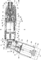
本実施形態に係る電動工具10のハウジング11は、図1に示すように、筒状のハウジング本体12と、そのハウジング本体12の基端部に上下回動可能な状態で連結されたグリップ部15とから構成されている。グリップ部15は、使用者が電動工具10を使用する際に把持する部分であり、左右の半筒状のグリップ片150a,150b(図5参照)が合わせられることで筒状に形成され、その内側に電池収納部15e(図1参照)が設けられている。電池収納部15eは、電池パック18のケース本体部18mを収納する部分であり、グリップ部15の先端側(図1において下端側)に開口15hを備えている。電池パック18は、電動工具10用のバッテリと、そのバッテリを収納するケースとからなる電池ユニットで、ケース本体部18mとグリップ形成部18zとから構成されている。そして、電池パック18のケース本体部18mがグリップ部15の電池収納部15eに全体的に挿入されることで、電池パック18がグリップ部15に連結されるとともに、その電池パック18のバッテリと電動工具10の電気回路とが電気的に接続される。また、この状態で、電池パック18のグリップ形成部18zがグリップ部15の先端部分を構成する。
<About the configuration of the power tool>
As shown in FIG. 1, the
ハウジング本体12は、二つ割りタイプのハウジングで、図4に示すように、半筒状の左ハウジング片120aと右ハウジング片120bが相互に接合されることにより筒状に形成される。ハウジング本体12には、前側から順番にギヤ部20と、モータ30と、スイッチ40と、素子ケース50とが同軸に収納されている。ギヤ部20は、図1、図3に示すように、モータ30の回転を減速させる遊星歯車機構24と、遊星歯車機構24によって回転させられるスピンドル25と、スピンドル25の回転力を回転打撃力に変換する打撃力発生機構26と、打撃力発生機構26の回転打撃力を受けるアンビル27とを備えている。そして、アンビル27が軸受27jによって軸回りに回転自在に支持されている。また、アンビル27の先端部には、ドライバビットやソケットビット等(図示省略)の先端工具を装着するためのチャック部27tが設けられている。
As shown in FIG. 4, the
モータ30は、図1から図4に示すように、円柱形状に形成されて、その前端面中央と後端面中央とに、そのモータ30の回転軸32を支持する前部軸受33と後部軸受34(図4参照)とが設けられている。モータ30の回転軸32は、図1、図3に示すように、前部軸受33から前方に突出しており、その回転軸32の突出端にモータ側歯車32wが設けられている。そして、前記モータ側歯車32wが遊星歯車機構24の一対の遊星歯車24rと噛合している。また、前記モータ30の前部軸受33が遊星歯車機構24の外輪歯車24zを備えるケース部24cの軸受支持部24jに嵌め込まれている。この状態で、モータ30がギヤ部20の遊星歯車機構24に対して同軸に連結される。
また、モータ30の後端面外周には、図4に示すように、後部軸受34を挟んで向かい合う位置に、一対のターミナル36が軸方向に突出するように設けられている。
As shown in FIGS. 1 to 4, the
Further, as shown in FIG. 4, a pair of
スイッチ40は、モータ30の正転、逆転の切替え、モータ30の回転速度調整、及び照明用LED13の点灯、消灯を行うスイッチである。スイッチ40は、スイッチ回路を収納する筒状のスイッチ本体部42と、そのスイッチ本体部42を覆い、前記スイッチ本体部42に対して同軸に回転できるように構成された円筒状のトリガ44とから構成されている。そして、スイッチ本体部42に対してトリガ44が基準位置から右方向に回転することで、照明用LED13の点灯し、モータ30が正転するとともに、トリガ44の回転角度の増加に伴ってモータ30の回転速度が増加するようになる。また、トリガ44が基準位置から左方向に回転することで、照明用LED13の点灯し、モータ30が逆転するとともに、トリガ44の回転角度の増加に伴ってモータ30の回転速度が増加するようになる。
The
スイッチ40のスイッチ本体部42の前端面には、図4に示すように、モータ30のターミナル36に対応する位置に、そのターミナル36が挿入される開口42xが形成されており、その開口42xの内側にターミナル36が接続されるスイッチ側端子42tが配置されている。また、スイッチ本体部42の前端面中央には、モータ30の後部軸受34が嵌め込まれる円筒状凹部42hが形成されている。
即ち、スイッチ本体部42の開口42xにモータ30のターミナル36が挿入されてスイッチ側端子42tに接続され、そのモータ30の後部軸受34がスイッチ本体部42の円筒状凹部42hに嵌め込まれることで、モータ30とスイッチ40とが同軸に連結される。
また、スイッチ40のスイッチ本体部42の後端面には、図3等に示すように、側面略逆L字形をした素子ケース50が縦向きに固定される。素子ケース50は、モータ30の回転制御を行なう電子素子(FET)やそれを保護する電子素子(ダイオード)を収納するケースであり、その外側に電動工具10の電気回路の電源端子(図示省略)を備えている。
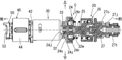
即ち、ハウジング本体12に収納されるギヤ部20と、モータ30と、スイッチ40と、素子ケース50とは、図3に示すように、直列に連結されて部品連結体Cを構成できるように製作されている。
このように、ギヤ部20、モータ30、スイッチ40、及び素子ケース50が本発明の部品に相当する。
As shown in FIG. 4, an opening 42x into which the terminal 36 is inserted is formed on the front end surface of the switch
That is, the
Further, as shown in FIG. 3 and the like, an
That is, the
Thus, the
<ハウジング本体12の構成について>
ハウジング本体12の先端には、図1、図5に示すように、ギヤ部20のアンビル27の軸受27jを支持する軸受支持部12hが形成されており、その軸受支持部12hの後側にアンビル27のケース27cを半径方向外側及び前側から支える前部支持部12fが形成されている。ここで、ハウジング本体12を構成する左ハウジング片120a、右ハウジング片120bは、図4に示すように、アンビル27のケース27cにネジ止めされるようになっている。また、ハウジング本体12の前部支持部12fの下部に、図1に示すように、照明用LED13が取付けられている。
ハウジング本体12の前後方向における中央位置には、図5に示すように、ギヤ部20を構成する遊星歯車機構24のケース部24cの外周部分が嵌め込まれる浅溝部12mが円周方向に延びるように形成されている。さらに、ハウジング本体12には、浅溝部12mの後側に左ハウジング片120a、右ハウジング片120bを連結するためのネジを通すネジ支持部12b(図1参照)が上下に形成されている。そして、上下のネジ支持部12bによって、遊星歯車機構24のケース部24cが後方から支持されている。
即ち、ギヤ部20は、ハウジング本体12の軸受支持部12h、前部支持部12fによって前側から支持され、ハウジング本体12の浅溝部12m、ネジ支持部12bによって後側から支持されて、ハウジング本体12の軸方向に位置決めされる。
<About the structure of the
As shown in FIGS. 1 and 5, a
As shown in FIG. 5, a
That is, the
ハウジング本体12の後部の左右両側には、図5に示すように、スイッチ40のトリガ44に相当する位置に角形開口12kが形成されており、その角形開口12kの位置でトリガ44の外側面の一部が露出している。これにより、前記スイッチ40のトリガ44をハウジング本体12の外側から回転操作できるようになる。
ハウジング本体12は、スイッチ40の収納部分の後側で高さ寸法と幅寸法とがそれぞれ減少して、縦方向段差部12p(図1参照)と左右対称な横方向段差部12q(図5参照)とが形成されている。そして、縦方向段差部12pと左右の横方向段差部12qとの後側に扁平箱形の基端部(後端部)120が形成されて、その基端部120の位置に、図1、図2に示すように、前記素子ケース50が収納されている。
ハウジング本体12の基端部120は、グリップ部15に連結される部分であり、その基端部120の中央位置に円筒部122が水平方向(左右方向)に延びて前記基端部120を貫通するように形成されている。そして、ハウジング本体12の基端部120の内側に位置する円筒部122の外周面前側位置に、図2に示すように、その円筒部122の軸方向(左右方向)に延びる断面円弧状の溝122mが上下に形成されている。円筒部122は、後記するように、グリップ部15の連結軸部153(図2、図5参照)を回転自在に支持するとともに、前記スイッチ40に固定された素子ケース50を後方から支える働きをする。そして、素子ケース50の後端面52と円筒部122との間に軸状の弾性体124が円弧状の溝122mに嵌合した状態で挟持されている。即ち、ギヤ部2と、モータ30と、スイッチ40と、素子ケース50とからなる部品連結体Cの後端が円筒部122と軸状の弾性体124とによって後方から支持される。
即ち、ハウジング本体12の円筒部122が本発明の部品連結体を軸方向の他端側から支持する突起部に相当し、ハウジング本体12の軸受支持部12h、前部支持部12f、浅溝部12m、ネジ支持部12b等が本発明の部品連結体を軸方向の一端側から支持する突起部に相当する。
As shown in FIG. 5, a
The
A
That is, the
<ハウジング本体12とグリップ部15との連結構造について>
グリップ部15の基端部は、ハウジング本体12の基端部120に連結される部分であり、図5に示すように、左右のグリップ片150a、150bにそれぞれ形成された支持壁部150を備えている。そして、左右の支持壁部150の間にハウジング本体12の基端部120が嵌め込まれる凹部152が形成されている。グリップ部15の凹部152の中央位置には、左方の支持壁部150から右方の支持壁部150まで連結軸部153が水平に渡されており、その連結軸部153が上記したようにハウジング本体12の円筒部122に挿入されている。これにより、ハウジング本体12の基端部120とグリップ部15の基端部とが連結軸部153を中心にして上下方向に相対回転可能な状態で連結される。
グリップ部15の連結軸部153は筒状に形成されており、その内側に左グリップ片150aと右グリップ片150bとを接合させるためのネジNが通されるようになっている。
<About the connection structure between the
The base end portion of the
The connecting
<本実施形態に係る電動工具10の長所について>
本実施形態に係る電動工具10では、複数の部品(ギヤ部20、モータ30、スイッチ40、及び素子ケース50)を直列に連結して部品連結体Cを形成し、この部品連結体Cをハウジング本体12の円筒部122、軸受支持部12h、前部支持部12f等(突起部)により軸方向一端側と他端側とから支持し、前記ハウジング本体12に対して軸方向に位置決めする構成である。このため、各々の部品間に突起部を配置する必要がなくなり、その突起部の省略分だけ部品連結体Cの全長寸法を小さくできる。これにより、ハウジング本体12の全長寸法、即ち、電動工具10の全長寸法を小さくできる。さらに、ハウジング本体12の突起部の数も少なくできることからハウジング本体12の内側形状も簡素化できる。
ここで、複数の部品を直列に連結して部品連結体Cを構成する場合、個々の部品の製作誤差に起因して部品連結体Cの長さ方向における累積公差が大きくなる。しかし、部品連結体Cとハウジング本体12の円筒部122(突起部)との間には弾性体124が挟持されているため、その弾性体124の弾性変形分で部品連結体Cの長さ方向における累積公差を吸収でき、モータ30やスイッチ40の耐久性が向上する。
<Advantages of the
In the
Here, when a plurality of components are connected in series to form the component coupling body C, the accumulated tolerance in the length direction of the component coupling body C increases due to manufacturing errors of individual components. However, since the
また、ハウジング本体12の基端部120は扁平箱状に形成されて、グリップ部15の凹部152内に嵌め込まれており、そのハウジング本体12の基端部120内に円筒部122(突起部)と弾性体124とが設けられている。 即ち、扁平箱形で部品の収納には不適切な部分に突起部122と弾性体124とを収納できるため、ハウジング本体12内の部品収納スペースが突起部122と弾性体124によって狭められず、ハウジング本体12内のスペースを有効に利用できる。
また、ハウジング本体12の円筒部122(突起部)の外周面には断面円弧状の溝122mがその円筒部122の軸方向に延びるように形成されて、その溝122mに軸状の弾性体124が嵌め込まれる構成である。このため、弾性体124を安定した状態でハウジング本体12の円筒部122(突起部)と部品連結体C(素子ケースの後端面52)との間に挟持することができる。また、弾性体124が軸状に形成されているため、平板状の弾性体と比較して弾性変形代を大きくできる。
Further, the
Further, a
<変更例>
ここで、本発明は上記実施形態に限定されるものではなく、本発明の要旨を逸脱しない範囲における変更が可能である。例えば、本実施形態では、円筒部122の外周面に断面円弧状の溝122mを形成し、その溝122mに嵌るように弾性体124を軸状に形成する例を示した。しかし、前記溝を、例えば、断面角形に形成し、弾性体を角柱状に形成することも可能である。また、軸状の弾性体の代わりに、例えば、板バネ等を使用することも可能である。
また、本実施形態では、本発明をペンインパクトドライバに適用する例を示したが、通常のインパクトドライバに本発明を適用することも可能である。さらに、本発明をスクリュドライバやドリル等に適用することも可能である。
<Example of change>
Here, the present invention is not limited to the above-described embodiment, and can be modified without departing from the gist of the present invention. For example, in the present embodiment, an example is shown in which a
In this embodiment, an example in which the present invention is applied to a pen impact driver has been described. However, the present invention can also be applied to a normal impact driver. Furthermore, the present invention can be applied to a screw driver, a drill, or the like.
12・・・・ハウジング本体
12f・・・前部支持部(突起部)
12m・・・浅溝部(突起部)
12h・・・軸受支持部(突起部)
15・・・・グリップ部
18・・・・電池パック
20・・・・ギヤ部(部品)
30・・・・モータ(部品)
40・・・・スイッチ(部品)
42・・・・スイッチ本体部
44・・・・トリガ
50・・・・素子ケース(部品)
122・・・円筒部(突起部)
122m・・溝
124・・・弾性体
152・・・凹部
C・・・・・部品連結体
12 ....
12m ... Shallow groove (projection)
12h ... Bearing support (protrusion)
15 ...
30 ... Motor (parts)
40 .... Switch (parts)
42...
122 ... cylindrical part (protrusion part)
122 m ··· groove 124 ···
Claims (4)
前記複数の部品を直列に連結することにより構成された部品連結体が、前記ハウジング本体の内壁面に形成された複数の突起部により、軸方向における一端側と他端側とから支持されて、そのハウジング本体に対して軸方向に位置決めされる構成であり、
前記部品連結体と前記ハウジング本体の基端部に設けられている突起部との間には、前記ハウジング本体の軸方向に対して交差する方向に延びる軸状の弾性体が挟持されていることを特徴とする電動工具。 A power tool comprising a housing composed of a cylindrical housing body and a grip portion, wherein a plurality of components are housed in series in the axial direction in the housing body,
A component coupling body configured by coupling the plurality of components in series is supported from one end side and the other end side in the axial direction by a plurality of protrusions formed on the inner wall surface of the housing body, It is configured to be axially positioned with respect to the housing body,
A shaft-like elastic body extending in a direction intersecting the axial direction of the housing main body is sandwiched between the component coupling body and the protrusion provided at the base end portion of the housing main body. An electric tool characterized by
前記ハウジング本体の基端部は扁平容器状に形成されて、グリップ部の凹部内に嵌め込まれており、
前記ハウジング本体の基端部内に前記突起部と前記弾性体とが設けられていることを特徴とする電動工具。 The electric tool according to claim 1,
The base end portion of the housing body is formed in a flat container shape, and is fitted in the recess of the grip portion,
The power tool, wherein the protrusion and the elastic body are provided in a base end portion of the housing body.
前記ハウジング本体の基端部には、その基端部を貫通するように円筒部が形成され、前記円筒部に対して前記グリップ部の凹部の位置に設けられた連結軸部が通されて、前記ハウジング本体が前記グリップ部に対し、前記連結軸部回りに回動可能に構成されており、
前記ハウジング本体の円筒部の外周面には前記突起部として機能する断面円弧状の溝がその円筒部の軸方向に延びるように形成されて、その溝に軸状の前記弾性体が嵌め込まれていることを特徴とする電動工具。 The electric tool according to claim 2,
A cylindrical portion is formed in the base end portion of the housing main body so as to penetrate the base end portion, and a connecting shaft portion provided at a position of the concave portion of the grip portion is passed through the cylindrical portion, The housing body is configured to be rotatable around the connecting shaft portion with respect to the grip portion,
A circular arc-shaped groove that functions as the protrusion is formed on the outer peripheral surface of the cylindrical portion of the housing body so as to extend in the axial direction of the cylindrical portion, and the shaft-shaped elastic body is fitted into the groove. An electric tool characterized by having
前記部品連結体は、先端工具を回転させるギヤ部と、駆動源であるモータと、前記モータを動作させるスイッチと、前記スイッチの信号に基づいて前記モータの回転制御を行なう電子素子のケースとが直列に連結される構成であることを特徴とする電動工具。 The electric tool according to any one of claims 1 to 3,
The component coupling body includes a gear unit that rotates a tip tool, a motor that is a driving source, a switch that operates the motor, and a case of an electronic element that controls rotation of the motor based on a signal of the switch. An electric tool characterized by being connected in series.
Priority Applications (4)
| Application Number | Priority Date | Filing Date | Title |
|---|---|---|---|
| JP2009183425A JP5420342B2 (en) | 2009-08-06 | 2009-08-06 | Electric tool |
| CN201010247923.9A CN101992457B (en) | 2009-08-06 | 2010-08-04 | Power tools |
| US12/850,154 US8413743B2 (en) | 2009-08-06 | 2010-08-04 | Power tools |
| EP10008181.9A EP2281663B1 (en) | 2009-08-06 | 2010-08-05 | Power tools |
Applications Claiming Priority (1)
| Application Number | Priority Date | Filing Date | Title |
|---|---|---|---|
| JP2009183425A JP5420342B2 (en) | 2009-08-06 | 2009-08-06 | Electric tool |
Publications (2)
| Publication Number | Publication Date |
|---|---|
| JP2011036924A JP2011036924A (en) | 2011-02-24 |
| JP5420342B2 true JP5420342B2 (en) | 2014-02-19 |
Family
ID=43063635
Family Applications (1)
| Application Number | Title | Priority Date | Filing Date |
|---|---|---|---|
| JP2009183425A Active JP5420342B2 (en) | 2009-08-06 | 2009-08-06 | Electric tool |
Country Status (4)
| Country | Link |
|---|---|
| US (1) | US8413743B2 (en) |
| EP (1) | EP2281663B1 (en) |
| JP (1) | JP5420342B2 (en) |
| CN (1) | CN101992457B (en) |
Families Citing this family (9)
| Publication number | Priority date | Publication date | Assignee | Title |
|---|---|---|---|---|
| EP2289670B1 (en) * | 2009-08-31 | 2012-07-11 | Robert Bosch GmbH | Rotary power tool |
| JP5593200B2 (en) | 2010-10-27 | 2014-09-17 | 株式会社マキタ | Electric tool system |
| JP5663353B2 (en) | 2010-10-27 | 2015-02-04 | 株式会社マキタ | Electric tool system |
| JP2013094877A (en) * | 2011-10-31 | 2013-05-20 | Hitachi Koki Co Ltd | Power tool |
| DE202013103023U1 (en) * | 2012-07-14 | 2013-10-04 | Hitachi Koki Co., Ltd. | power tool |
| JP2014172118A (en) * | 2013-03-08 | 2014-09-22 | Hitachi Koki Co Ltd | Electric power tool |
| CN107848105B (en) * | 2015-06-30 | 2021-07-20 | 工机控股株式会社 | Working machine |
| JP6849088B2 (en) * | 2017-09-29 | 2021-03-24 | 工機ホールディングス株式会社 | Electrical equipment |
| TWI660806B (en) * | 2018-07-09 | 2019-06-01 | 愛烙達股份有限公司 | Hand-held tool |
Family Cites Families (18)
| Publication number | Priority date | Publication date | Assignee | Title |
|---|---|---|---|---|
| DE4000861C3 (en) | 1990-01-13 | 1999-04-08 | Atlas Copco Electric Tools | Hand-held impact drill with vibration damping |
| DE19730356C2 (en) | 1997-07-15 | 2001-05-17 | Wacker Werke Kg | Vibration-damped breaker and / or hammer drill |
| US6102134A (en) * | 1998-10-16 | 2000-08-15 | Black & Decker Inc. | Two-position screwdriver |
| US6318479B1 (en) * | 1999-10-01 | 2001-11-20 | Chicago Pneumatic Tool Company | Vibration isolated impact wrench |
| US6321853B2 (en) | 1999-10-01 | 2001-11-27 | Chicago Pneumtic Tool Company | Vibration isolated impact wrench |
| TW492383U (en) * | 2001-05-15 | 2002-06-21 | Mobiletron Electronics Co Ltd | Multi-segment bending structure for joints of electromotive screwdriver |
| US6364033B1 (en) * | 2001-08-27 | 2002-04-02 | Techtronic Industries Co. Ltd. | Portable electric tool |
| DE10259518A1 (en) | 2002-12-19 | 2004-07-01 | Robert Bosch Gmbh | housing unit |
| CN2644105Y (en) * | 2003-05-27 | 2004-09-29 | 车王电子股份有限公司 | Electric tool with multiple working angle |
| DE10361812A1 (en) * | 2003-12-30 | 2005-07-28 | Robert Bosch Gmbh | Hand tool |
| DE102004051465A1 (en) * | 2004-10-22 | 2006-04-27 | Robert Bosch Gmbh | Hand tool with vibration damped pistol handle |
| EP1674212B1 (en) | 2004-12-23 | 2008-05-28 | BLACK & DECKER INC. | Power tool housing |
| CN1891414A (en) * | 2005-05-17 | 2007-01-10 | 密尔沃基电动工具公司 | Power tool, battery, charger and method of operating the same |
| DE102006023187B4 (en) * | 2005-05-17 | 2020-02-27 | Milwaukee Electric Tool Corp. | Method for operating a battery charger and a combination comprising a battery and a battery charger |
| US7649337B2 (en) * | 2005-05-17 | 2010-01-19 | Milwaukee Electric Tool Corporation | Power tool including a fuel gauge and method of operating the same |
| DE102005059180A1 (en) * | 2005-12-12 | 2007-06-14 | Robert Bosch Gmbh | Hand tool with a drive train and a decoupling unit |
| JP4754395B2 (en) * | 2006-04-20 | 2011-08-24 | 株式会社マキタ | Screwing machine |
| US7896103B2 (en) * | 2008-02-04 | 2011-03-01 | Ingersoll Rand Company | Power tool housing support structures |
-
2009
- 2009-08-06 JP JP2009183425A patent/JP5420342B2/en active Active
-
2010
- 2010-08-04 CN CN201010247923.9A patent/CN101992457B/en active Active
- 2010-08-04 US US12/850,154 patent/US8413743B2/en active Active
- 2010-08-05 EP EP10008181.9A patent/EP2281663B1/en active Active
Also Published As
| Publication number | Publication date |
|---|---|
| CN101992457A (en) | 2011-03-30 |
| US8413743B2 (en) | 2013-04-09 |
| EP2281663A3 (en) | 2011-07-13 |
| EP2281663A2 (en) | 2011-02-09 |
| EP2281663B1 (en) | 2015-04-01 |
| US20110030986A1 (en) | 2011-02-10 |
| CN101992457B (en) | 2012-11-21 |
| JP2011036924A (en) | 2011-02-24 |
Similar Documents
| Publication | Publication Date | Title |
|---|---|---|
| JP5420342B2 (en) | Electric tool | |
| CN107443321B (en) | Electric tool | |
| JP6050110B2 (en) | Impact tools | |
| JP4084319B2 (en) | Electric tool | |
| JP2017100259A (en) | Electric tool with vibration mechanism | |
| CA2735034A1 (en) | A portable angle impact tool | |
| CN112238411B (en) | Electric tool and rotary tool | |
| JP6397594B2 (en) | Impact driver, driver drill, power tool | |
| JP2007105816A (en) | Battery type power tool | |
| JP2018183874A (en) | Power tool | |
| JP2016215373A (en) | Angle tool | |
| CA2735028A1 (en) | A portable angle impact tool | |
| US20110278033A1 (en) | Portable angle impact tool | |
| JP2016165767A (en) | Rotary impact tool | |
| JP4188792B2 (en) | motor | |
| JP7426831B2 (en) | impact tools | |
| JP7129871B2 (en) | impact tools and power tools | |
| JP6615298B2 (en) | Power tools | |
| JP2014104569A (en) | Power tool | |
| JP6364646B2 (en) | Electric tool | |
| JP6249575B2 (en) | Impact tools | |
| JP2020196052A (en) | Electric tool | |
| JP7462273B2 (en) | Impact rotary tool | |
| JP2021016936A (en) | Power tool and rotary tool | |
| JP2023181600A (en) | Impact tool |
Legal Events
| Date | Code | Title | Description |
|---|---|---|---|
| A621 | Written request for application examination |
Free format text: JAPANESE INTERMEDIATE CODE: A621 Effective date: 20120228 |
|
| A977 | Report on retrieval |
Free format text: JAPANESE INTERMEDIATE CODE: A971007 Effective date: 20130531 |
|
| A131 | Notification of reasons for refusal |
Free format text: JAPANESE INTERMEDIATE CODE: A131 Effective date: 20130625 |
|
| A977 | Report on retrieval |
Free format text: JAPANESE INTERMEDIATE CODE: A971007 Effective date: 20130731 |
|
| A521 | Request for written amendment filed |
Free format text: JAPANESE INTERMEDIATE CODE: A523 Effective date: 20130808 |
|
| A131 | Notification of reasons for refusal |
Free format text: JAPANESE INTERMEDIATE CODE: A131 Effective date: 20130903 |
|
| A521 | Request for written amendment filed |
Free format text: JAPANESE INTERMEDIATE CODE: A523 Effective date: 20131017 |
|
| TRDD | Decision of grant or rejection written | ||
| A01 | Written decision to grant a patent or to grant a registration (utility model) |
Free format text: JAPANESE INTERMEDIATE CODE: A01 Effective date: 20131112 |
|
| A61 | First payment of annual fees (during grant procedure) |
Free format text: JAPANESE INTERMEDIATE CODE: A61 Effective date: 20131120 |
|
| R150 | Certificate of patent or registration of utility model |
Ref document number: 5420342 Country of ref document: JP Free format text: JAPANESE INTERMEDIATE CODE: R150 |
|
| R250 | Receipt of annual fees |
Free format text: JAPANESE INTERMEDIATE CODE: R250 |
|
| R250 | Receipt of annual fees |
Free format text: JAPANESE INTERMEDIATE CODE: R250 |
|
| R250 | Receipt of annual fees |
Free format text: JAPANESE INTERMEDIATE CODE: R250 |
|
| R250 | Receipt of annual fees |
Free format text: JAPANESE INTERMEDIATE CODE: R250 |
|
| R250 | Receipt of annual fees |
Free format text: JAPANESE INTERMEDIATE CODE: R250 |
|
| R250 | Receipt of annual fees |
Free format text: JAPANESE INTERMEDIATE CODE: R250 |
|
| R250 | Receipt of annual fees |
Free format text: JAPANESE INTERMEDIATE CODE: R250 |
|
| R250 | Receipt of annual fees |
Free format text: JAPANESE INTERMEDIATE CODE: R250 |