JP5419926B2 - A simple building with electronic equipment - Google Patents
A simple building with electronic equipment Download PDFInfo
- Publication number
- JP5419926B2 JP5419926B2 JP2011126424A JP2011126424A JP5419926B2 JP 5419926 B2 JP5419926 B2 JP 5419926B2 JP 2011126424 A JP2011126424 A JP 2011126424A JP 2011126424 A JP2011126424 A JP 2011126424A JP 5419926 B2 JP5419926 B2 JP 5419926B2
- Authority
- JP
- Japan
- Prior art keywords
- building
- heat exchanger
- ceiling plate
- roof
- intermediate ceiling
- Prior art date
- Legal status (The legal status is an assumption and is not a legal conclusion. Google has not performed a legal analysis and makes no representation as to the accuracy of the status listed.)
- Expired - Fee Related
Links
Images


Description
本発明は、例えば、ラックに収納した多数のサーバを集中して設置するデータセンターなど、コンピュータ等の電子機器を室内に集中管理する建造物、特に、移設や増設が簡易にできるよう構成された建造物に関するものである。 The present invention is configured to centrally manage electronic devices such as computers in a room, such as a data center in which a large number of servers housed in a rack are centrally installed, and in particular, can be easily moved or expanded. Concerning buildings.
インターネットの普及に代表されるコンピュータネットワークの発展に伴い、サーバと呼ばれる業務用の比較的大型で信頼性を重視したコンピュータ、あるいは主に記憶装置を収めたストレージなどのコンピュータの需要が、ネットワークのサービス提供業者を中心に近年急速に拡大している。サーバ等のコンピュータは、収納用の筐体であるラックに多数のものを収め、一個所で集中管理されることが多く、サーバ等を内部に集中して管理する建造物は、データセンターと呼ばれている。 With the development of computer networks represented by the spread of the Internet, the demand for computers such as servers, which are relatively large-sized business-use computers that emphasize reliability, or storage that mainly contains storage devices, is the network service. In recent years, the number of providers has been increasing rapidly. Computers such as servers are housed in a rack, which is a housing for storage, and are often centrally managed in one place. A building that centrally manages servers is called a data center. It is.
データセンターには、通常の建築物として構築されるもの以外に、輸送用の大型容器であるコンテナを改造して構築するコンテナ型データセンター(モジュール型データセンターともいわれる)が存在する。輸送用のコンテナは、周囲を強度の大きい壁面で取り囲まれた堅牢な構造であって、データセンターのセキュリティを確保するのが容易であるとともに、気密性が高く、塵埃の侵入や塩害(海岸付近に設置される場合)を防止してコンピュータを保護するのも容易である。また、コンテナ型データセンターは、輸送用のコンテナを基礎とする、通常の建築物と比較すると小型の建造物であるので、その増設や移設が簡単であり、無人運転に適しているという利点もある。 In addition to what is constructed as a normal building, there are container-type data centers (also called modular data centers) that are constructed by modifying containers that are large containers for transportation. The shipping container has a robust structure surrounded by a strong wall around it, making it easy to ensure the security of the data center and high airtightness. It is easy to protect the computer by preventing (if installed). Container-type data centers are small buildings compared to ordinary buildings based on transportation containers, so they can be easily expanded and relocated and are suitable for unmanned operation. is there.
コンテナ型データセンターの増設に容易に対応できるよう、棚状のコンテナ格納部を上下方向及び横方向に複数形成した、鉄骨構造の大規模な建築物が、特開2011−18220号公報に開示されている。この建築物は、図7に示すとおり、複数の鋼材の柱PLと梁BMとを組み合わせた格子構造を備え、格子構造の各区画に、データセンターとしてのコンテナCTが収められる。コンテナCTの前方には、保守管理のための通路WYが設けられるとともに、後方側には、移動可能なエレベータ(図示せず)が設けられており、コンテナCTは、エレベータによって収納場所に容易に設置される。 Japanese Laid-Open Patent Publication No. 2011-18220 discloses a large-scale building with a steel structure in which a plurality of shelf-shaped container storage units are formed in the vertical and horizontal directions so that the expansion of a container-type data center can be easily accommodated. ing. As shown in FIG. 7, this building has a lattice structure in which a plurality of steel pillars PL and beams BM are combined, and a container CT as a data center is stored in each section of the lattice structure. A passage WY for maintenance management is provided in front of the container CT, and a movable elevator (not shown) is provided on the rear side. The container CT can be easily placed in a storage place by the elevator. Installed.
ところで、多数のコンピュータを備えたデータセンター等の建造物においては、コンピュータの発熱に起因する熱障害を防止し、併せて室内の空調を行う必要がある。コンピュータの冷却や室内の空調を行うには、冷凍サイクルを実行する空調機を設置してコンピュータ等いわば強制的に冷却してもよいが、冷媒の相変化を利用するヒートパイプと同様な熱伝達促進装置を用いて、室内の熱を外部の大気に積極的に排熱することによりコンピュータの熱障害を防止する冷却装置も知られており、例えば、特開2011−38734号公報に開示されている。 By the way, in a building such as a data center equipped with a large number of computers, it is necessary to prevent thermal failure caused by the heat generated by the computers and to perform indoor air conditioning. In order to cool the computer or to air-condition the room, an air conditioner that executes the refrigeration cycle may be installed to forcibly cool the computer, but the heat transfer is similar to a heat pipe that uses the phase change of the refrigerant. There is also known a cooling device that prevents a thermal failure of a computer by actively exhausting indoor heat to the outside atmosphere using an accelerating device, and is disclosed in, for example, Japanese Patent Application Laid-Open No. 2011-38734. Yes.
上記公報に記載の冷却装置は、携帯電話等の電話基地局に収容された情報通信機器を冷却(温度上昇を抑制)するためのものであり、図8に示されるように、電話基地局の屋外に室外熱交換器LE(低温熱交換器)を設置するとともに、情報通信機器が設置された室内Rの上方に室内熱交換器HE(高温熱交換器)を設置する。両方の熱交換器は連通されて内部に冷媒が封入されており、情報通信機器から発生した熱によって室内熱交換器HEの冷媒が沸騰して室外熱交換器LEに移送され、ここで、大気に熱を放出して冷媒が凝縮し、重力で室内熱交換器HEに還流する。室内の空気は、室内側ファンRFにより循環され、温度の下降した室内熱交換器HEを通過して冷却される。
外気冷却によるこの装置は、温度差に基づく対流を利用する自然循環式の冷却装置であって、冷凍サイクルを行うものではないから、基本的に外部電力等が不要である。したがって、この冷却装置をデータセンターに採用したときは、サーバ等のコンピュータで使用する電力以外のものは殆ど必要なく、消費電力の大幅な削減が可能となる。
The cooling device described in the above publication is for cooling information communication equipment accommodated in a telephone base station such as a mobile phone (suppressing temperature rise). As shown in FIG. An outdoor heat exchanger LE (low temperature heat exchanger) is installed outdoors, and an indoor heat exchanger HE (high temperature heat exchanger) is installed above the room R where the information communication equipment is installed. Both heat exchangers are connected to each other and a refrigerant is sealed inside, and the refrigerant generated in the indoor heat exchanger HE is boiled by the heat generated from the information communication device and transferred to the outdoor heat exchanger LE. The refrigerant is condensed by discharging heat to the indoor heat exchanger HE by gravity. The indoor air is circulated by the indoor fan RF and is cooled by passing through the indoor heat exchanger HE whose temperature has dropped.
This device based on the outside air cooling is a natural circulation type cooling device that uses convection based on a temperature difference, and does not perform a refrigeration cycle. Therefore, external power or the like is basically unnecessary. Therefore, when this cooling device is employed in a data center, almost no power other than that used by a computer such as a server is required, and power consumption can be greatly reduced.
データセンターあるいは電話基地局など、コンピュータ等の電子機器を多数収容する建造物においては、コンピュータの十分なセキュリティの確保が要請されるとともに、塵埃や塩害等からのコンピュータの保護が要請される。こうした要請に応じるには、建造物の密閉性を高めて室内を外部から遮断することが可能でなければならないが、一方では、コンピュータの発熱に起因する熱障害を防ぐため、室内の熱を外部に放出しながらコンピュータを確実に冷却する必要がある。このとき、最近のデータセンターでは、コンピュータ作動の電力以外の、室内冷却用の電力等は極力抑制するよう求められている。また、コンテナ型データセンターのような小型の設備では、作業員等の常駐しない無人運転が可能であることが望ましく、これは、作業員用の空調の必要性を省いて消費電力の削減にも繋がることとなる。 In buildings that contain a large number of electronic devices such as computers such as data centers or telephone base stations, it is required to ensure sufficient security of computers and to protect computers from dust and salt damage. In order to meet these requirements, it must be possible to enhance the sealing of the building and block the room from the outside. On the other hand, to prevent thermal damage caused by computer heat, It is necessary to cool the computer securely while discharging it. At this time, in recent data centers, it is required to suppress as much as possible electric power for room cooling other than electric power for computer operation. In addition, it is desirable that small equipment such as container-type data centers can be operated unattended by workers, etc., which reduces power consumption by eliminating the need for air conditioning for workers. It will be connected.
そして、コンテナ型データセンターは、サーバ等の需要の増減に対応して、データセンターの建造物自体も容易に増設や撤去が可能であることが望ましい。特許文献1に開示される建築物は、コンテナ型データセンターの増設等の容易化を図ったものではあるが、鉄骨構造を基本とする非常に大規模な建築物であって、構築のために多大なコストを要し、極めて大量のサーバ等を必要とする場合以外には、不向きである。
本発明の課題は、データセンター等の建造物において、収容された多数のコンピュータ等を効率的に冷却し、かつ、建造物の構造を改良して増設や移設を容易化し、このような問題を解決することにある。
In addition, it is desirable that the container-type data center can be easily expanded or removed in accordance with the increase or decrease in demand for servers or the like. The building disclosed in Patent Document 1 is intended to facilitate the expansion of container-type data centers, etc., but is a very large-scale building based on a steel structure. It is not suitable unless it requires a great deal of cost and requires a very large number of servers.
An object of the present invention is to efficiently cool a large number of accommodated computers in a building such as a data center and improve the structure of the building to facilitate expansion and relocation. There is to solve.
上記の課題に鑑み、本発明は、建造物の4隅に配置した柱状部材の上部及び下部に緊締具の係合可能な締結金具を固着し、建造物の屋根の下方には中間天井板を設け、電子機器を中間天井板の下側室内に収め、かつ、中間天井板を挟むように電子機器の冷却装置を配置するものである。すなわち、本発明は、
「電子機器を室内に収めた建造物であって、
前記建造物は、平面視で長方形の形状を有し、その長方形の4隅には柱状部材が配置されるとともに、各々の前記柱状部材の上部及び下部には、緊締具の係合可能な締結金具が固着され、
前記建造物の屋根は、上部に固着された前記締結金具よりも低くなる位置に設置されており、さらに、
前記建造物の屋根の下方には中間天井板が設けられ、前記電子機器が前記中間天井板の下側に形成される室内に収められており、
前記中間天井板の下側に形成される室内には、室内の空気を冷却する熱交換器と冷却された空気を循環するファンとが設けられ、かつ、前記建造物の屋根と前記中間天井板との間には、前記熱交換器が吸収した熱を外気に排熱する室外熱交換器が設置される」
ことを特徴とする建造物となっている。
In view of the above problems, the present invention secures fasteners capable of engaging fasteners to the upper and lower portions of columnar members arranged at the four corners of a building, and has an intermediate ceiling plate below the roof of the building. The electronic device is placed in a lower chamber of the intermediate ceiling plate, and the electronic device cooling device is disposed so as to sandwich the intermediate ceiling plate. That is, the present invention
“It ’s a building with electronic equipment inside,
The building has a rectangular shape in plan view, and columnar members are arranged at four corners of the rectangle, and fasteners that can be engaged with fasteners are provided at the upper and lower portions of the columnar members. The bracket is fixed,
The roof of the building is installed at a position that is lower than the fasteners secured to the top, and
An intermediate ceiling plate is provided below the roof of the building, and the electronic device is housed in a room formed below the intermediate ceiling plate,
The room formed below the intermediate ceiling plate is provided with a heat exchanger for cooling indoor air and a fan for circulating the cooled air, and the roof of the building and the intermediate ceiling plate An outdoor heat exchanger that exhausts the heat absorbed by the heat exchanger to the outside air is installed between
The building is characterized by that.
請求項2に記載のように、前記中間天井板を、前記建造物の屋根の一部分において、その下方に設けることができる。 According to a second aspect of the present invention, the intermediate ceiling plate can be provided below a part of the roof of the building.
請求項3に記載のように、複数の前記電子機器をラックに収納するとともに、前記ラックの上方には、前記熱交換器を収めた熱交換器外箱を取り付け、前記熱交換器外箱を前記中間天井板に固定することが好ましい。
As claimed in
請求項4に記載のように、前記熱交換器と前記室外熱交換器とを連通し、その内部に、対流により循環する冷媒を封入して、室内の熱が前記室外熱交換器から排熱されるよう構成することができる。 According to a fourth aspect of the present invention, the heat exchanger and the outdoor heat exchanger are communicated with each other, and a refrigerant circulating by convection is enclosed therein, so that indoor heat is exhausted from the outdoor heat exchanger. Can be configured.
請求項5に記載のように、前記建造物の底部に、長方形の枠体を備えた底部フレームを設置し、前記底部フレームには、フォークリフトのフォークを挿入するフォークポケットを、長方形の長手方向と直角に延びるように固定することが好ましい。 A bottom frame having a rectangular frame is installed at the bottom of the building, and a fork pocket into which a fork of a forklift is inserted is formed in the bottom frame, and a longitudinal direction of the rectangle. It is preferable to fix so as to extend at a right angle.
また、請求項6に記載のように、前記建造物の端面の一方には、観音開き式のドアを設置するとともに、前記ドアを閉鎖するロックロッドを設け、かつ、前記ロックロッドの上端のカムと係合するカムキーパーを、前記建造物の屋根の下方において前記柱状部材を連結するように設けられた梁部材に固定することが好ましい。
In addition, as described in
電子機器を室内に収めた本発明の建造物は、平面視で長方形の形状を有し、その長方形の4隅には柱状部材が配置されるとともに、各々の前記柱状部材の上部及び下部には、緊締具の係合可能な締結金具が固着されている。つまり、本発明の建造物は、全体としては直方体の形状であって、船舶に積み重ねて積載される海上コンテナと同様に、直方体の8個の隅部に緊締具の係合可能な締結金具が固着されている。こうした締結金具は、コンテナの分野ではコーナーキャスティングと呼ばれ、一般的に使用される締結金具であり、コンテナ同士を連結するときには、ツイストコーン等の緊締具をこの締結金具に係合して積み重ね等が行われる。コンテナを陸上輸送するときは車輪付きのコンテナシャシに積載するが、これには、締結金具に係合するツイストロックがコンテナの寸法に合わせて装着されている。
本発明の建造物は、その屋根が上部に固着された締結金具よりも低くなる位置に設置されているので、建造物同士を直接積み重ねて連結することが可能である。そのため、電子機器の需要の増加に合わせて建造物を増設するときは、既存の建造物上に別のものを積載するだけで増設することができる。建造物を移設するときは、通常のコンテナシャシに積載して締結金具をツイストロックに緊締し、移動することができる。
The building of the present invention in which an electronic device is housed has a rectangular shape in plan view, and columnar members are arranged at the four corners of the rectangle, and the upper and lower portions of each of the columnar members are arranged. The fasteners that can be engaged with the fasteners are fixed. That is, the building of the present invention has a rectangular parallelepiped shape as a whole, and there are fasteners that can be engaged with fasteners at eight corners of the rectangular parallelepiped, similar to a marine container stacked and loaded on a ship. It is fixed. Such fasteners are called corner casting in the container field, and are commonly used fasteners. When connecting containers, a fastener such as a twist cone is engaged with the fasteners and stacked. Is done. When a container is transported by land, it is loaded on a container chassis with wheels, and a twist lock that engages with a fastener is attached to the container chassis according to the dimensions of the container.
Since the building of this invention is installed in the position where the roof becomes lower than the fastening metal fitting fixed to the upper part, it is possible to stack and connect buildings directly. Therefore, when a building is added in response to an increase in demand for electronic devices, the building can be added simply by loading another on the existing building. When relocating a building, it can be moved by loading it on a normal container chassis and tightening the fastening bracket to the twist lock.
そして、本発明の建造物では、屋根の下方に中間天井板が設けてあり、電子機器がこの中間天井板の下側に形成される室内に収められる。電子機器を収めた室内には、空気を冷却する熱交換器と冷却された空気を循環するファンとが設けられ、かつ、建造物の屋根と中間天井板との間には、室内の熱交換器が吸収した熱を外気に排熱する室外熱交換器が設置される。これにより、電子機器の効率的な冷却が可能であって、温度上昇による熱障害が防止される。また、室外熱交換器が屋根の下方に収容されるので、建造物同士を積み重ねるときの障害となることはない。
中間天井板は、屋根の下方の全面に亘り設置することもできるが、請求項2の発明のように、例えば室外熱交換器が存在する部分等、建造物の屋根の一部分においてその下方に設置してもよい。
And in the building of this invention, the intermediate ceiling board is provided under the roof, and an electronic device is stored in the room | chamber formed in the lower side of this intermediate ceiling board. The room containing the electronic equipment is provided with a heat exchanger that cools the air and a fan that circulates the cooled air, and heat exchange between the building roof and the intermediate ceiling plate An outdoor heat exchanger that exhausts the heat absorbed by the chamber to the outside air is installed. Thereby, the electronic device can be efficiently cooled, and a thermal failure due to a temperature rise is prevented. Moreover, since an outdoor heat exchanger is accommodated under the roof, it does not become an obstacle when stacking buildings.
The intermediate ceiling plate can be installed over the entire lower surface of the roof. However, as in the invention of
請求項3の発明は、複数の電子機器をラックに収納するとともに、ラックの上方には室内用の熱交換器を収めた熱交換器外箱を取り付け、この熱交換器外箱を中間天井板に固定するものである。この構成によれば、電子機器を収納したラックと電子機器の冷却装置とがユニット化されて、ラックが独立した冷却装置を備えることとなり、電子機器が稼動中のラックの冷却装置だけを作動させ、電力をその分削減することができる。また、ユニット化されたラック−熱交換器組立体の上部が中間天井板に固定されるため、電子機器収納体の耐震性を向上することができる。 According to a third aspect of the present invention, a plurality of electronic devices are accommodated in a rack, and a heat exchanger outer box containing an indoor heat exchanger is attached above the rack, and the heat exchanger outer box is attached to the intermediate ceiling plate. It is to be fixed to. According to this configuration, the rack in which the electronic device is stored and the cooling device for the electronic device are unitized, and the rack is provided with an independent cooling device. Only the cooling device for the rack in which the electronic device is operating is operated. , Power can be reduced accordingly. In addition, since the upper part of the unitized rack-heat exchanger assembly is fixed to the intermediate ceiling plate, the earthquake resistance of the electronic device housing can be improved.
本発明においては、電子機器を収めた室内の空気を冷却するため、圧縮機等を用いた冷凍サイクルを実行させ、冷凍サイクルのエバポレータ(蒸発器)を、熱交換器として室内に設置してもよいが、請求項4の発明は、室内の空気を冷却する熱交換器の上方に、その熱交換器と連通し室外に置かれた室外熱交換器を設け、両方の熱交換器の内部に対流により循環する冷媒を封入して、室内の熱を室外熱交換器から排熱するものである。これによれば、基本的に電力を使用することなく、自然対流を利用してコンピュータ等電子機器の冷却を行うことができる。
In the present invention, in order to cool indoor air containing electronic equipment, a refrigeration cycle using a compressor or the like is executed, and an evaporator (evaporator) of the refrigeration cycle is installed indoors as a heat exchanger. However, in the invention of
請求項5の発明のように、建造物の底部に底部フレームを設置し、これに、フォークリフトのフォークを挿入するフォークポケットを設けたときは、フォークリフトを使用して建造物の積み重ねや移動を行うことができる。つまり、建造物の積み重ねのために大規模なクレーン等の設備が必要なく、また、コンテナシャシへの積載も、フォークリフトを使用して簡単に行うことが可能となる。
When the bottom frame is installed at the bottom of the building and the fork pocket for inserting the fork of the forklift is provided on the bottom frame as in the invention of
請求項6の発明は、建造物の端面の一方に、観音開き式のドアを設置するとともにドアを閉鎖するロックロッドを設け、かつ、ロックロッドの上端のカムと係合するカムキーパーを、建造物の屋根の下方において柱状部材を連結するように設けられた梁部材に固定するものである。ロックロッドは、強度及び剛性の大きい棒材であって、これで閉鎖される観音開き式のドアは、建造物の出入口のセキュリティを高めることとなる。さらに、観音開き式のドアの両側に配置された、上下に締結金具を固着した柱状部材には、建造物の屋根の下方において梁部材が掛け渡されており、ロックロッドの上端のカムと係合するカムキーパーが、この梁部材に固定される。そのため、建造物を上下に積み重ねたときには、梁部材とロックロッドとが下側の建造物の補強材として作用し、また、柱状部材等の多少の変形があったとしても、カムとカムキーパーとを係合させロックロッドを強力に回転操作すると変形が回復し、ドアの閉鎖が可能となる。建造物の屋根と梁部材との間隙は、室外熱交換器のための外気流入口又は流出口として利用できる。 According to the sixth aspect of the present invention, a cam keeper is provided on one of the end faces of the building. The cam keeper is provided with a lock rod for installing a double door and closing the door, and is engaged with a cam at the upper end of the lock rod. It fixes to the beam member provided so that a columnar member may be connected under the roof of this. The lock rod is a bar having high strength and rigidity, and the double door that is closed by the lock rod increases the security of the entrance of the building. In addition, beam members are placed under the roof of the building on the columnar members, which are arranged on both sides of the double doors and fixed with fasteners on the top and bottom, and engage with the cam on the upper end of the lock rod. A cam keeper is fixed to the beam member. Therefore, when the building is stacked up and down, the beam member and the lock rod act as a reinforcement for the lower building, and even if there is some deformation of the columnar member, the cam and cam keeper When the lock rod is rotated strongly by engaging and the deformation is restored, the door can be closed. The gap between the roof of the building and the beam member can be used as an outside air inlet or outlet for the outdoor heat exchanger.
以下、図面に基づいて、データセンター等として用いられる本発明の建造物について説明する。
図1の全体図から分かるように、本発明の建造物は、輸送用のコンテナを基本とするコンテナ型データセンターとして構築されたものであって、全体としては6面体の直方体である箱型構造をなし、平面視では長方形の形状となっている。その長方形の4隅には、上下方向に延びる柱状部材1として、前部側の柱状部材1F及び後部側の柱状部材1Rが配置されるとともに(側面図では箱型構造の側壁を除いて示し、便宜上、左側を前部、右側を後部とする)、各々の柱状部材の上部及び下部には締結金具2が固着される。締結金具2は、建造物の最外方の部分に位置するよう、各々の柱状部材に固着されるもので、建造物の屋根3は、上部に固着された締結金具よりも低くなる位置に設置されている。建造物の内部は、サーバ、ストレージ等のコンピュータを室内に収めたコンピュータ室CRと、コンピュータ等に電力を供給する電源ユニットEUや予備空調用室外機CDなどを据え付けた機械室MRとに分割され、その間には仕切り壁が設置される。
Hereinafter, the building of the present invention used as a data center or the like will be described with reference to the drawings.
As can be seen from the overall view of FIG. 1, the building of the present invention is constructed as a container-type data center based on a container for transportation, and is a box-shaped structure that is a hexahedron as a whole. It has a rectangular shape in plan view. At the four corners of the rectangle, a
図2(a)は、前部側の柱状部材1Fを備えた前側フレーム枠体を、図2(b)は、後部側の柱状部材1Rを備えた後側フレーム枠体を示すものである。この実施例では、前部側の柱状部材1Fは扁平な角形の一様断面を有し、その上部及び下部に締結金具2が溶接により固着される。後部側の柱状部材1Rも、扁平な角形の一様断面を有し、上部及び下部に締結金具2の溶接されたものであるが、観音開きドアのヒンジを取り付ける4個の切り欠き部が途中に形成されている。図2(b)に示す後部側の柱状部材1Rには、建造物の屋根3の下方において、2本の柱状部材1Rを連結する梁部材4が掛け渡されている。この梁部材4には、観音開きドアを閉鎖するロックロッドLR(図1)のためのカムキーパーCKが固着される。
2A shows a front frame body provided with a front-
よく知られているように、ロックロッドは、上端及び下端にカム部材が一体的に固着された強度及び剛性の大きい棒材であり、カム部材は、フレームに固定されたカムキーパーと係合してドアを閉鎖する。カム部材は両側に二股部を備え、ロックロッドを回転させることによって、カムキーパーに形成された2個の突起に二股部がそれぞれ嵌め込まれるように構成されている(例えば、特開2000−129980号公報参照)。本発明の建造物では、出入口となる観音開きドアのロックロッドLRが、梁部材4と建造物の底部に置かれた底部フレーム5との間に、いわば補強用柱材として存在することになる。そのため、建造物の強度が増大し、積み重ねた場合でも変形が少なくなる。
As is well known, the lock rod is a bar having high strength and rigidity, with the cam member integrally fixed to the upper end and the lower end, and the cam member is engaged with a cam keeper fixed to the frame. Close the door. The cam member has bifurcated portions on both sides, and is configured such that the bifurcated portions are fitted into two protrusions formed on the cam keeper by rotating the lock rod (for example, Japanese Patent Laid-Open No. 2000-129980). See the official gazette). In the building of the present invention, the lock rod LR of the double door that serves as an entrance / exit exists between the
本発明の建造物で使用される締結金具2は、海上コンテナの隅部に置かれるコーナーキャスティングと同様な金具であり、この締結金具について図3により説明する。締結金具2は、6枚の厚板を組み合わせた直方体の強固な部品であって、柱状部材に溶接可能なように、通常は鋳鋼で製造される。建造物の外方となる面の厚板には、ツイストコーンTC等の緊締具を係合するための貫通孔が形成されている。建造物を積み重ねるときは、海上コンテナの積載と同じように、上側の締結金具2の貫通孔にツイストコーンTCの上側突起を嵌め込み、ツイストコーンTCを所定角度回転させて、下側突起を下方の締結金具2に嵌め込んで両者を連結する。ちなみに、陸上輸送用のコンテナシャシに装着されるツイストロックも、その上側突起をコンテナの下側のコーナーキャスティングに嵌め込み、所定角度回転させて固定するものである。
本発明の建造物は、締結金具2にツイストコーン等の緊締具を係合することにより、図4(a)に示されるように、直接積み重ねることが可能であり、サーバ等の需要の増大に対応して容易に増設することができる。場合によっては、図4(b)に示されるように、横方向に連結する緊締具を用いて並列的な増設も可能である。
The
The building of the present invention can be directly stacked as shown in FIG. 4A by engaging a fastener such as a twist cone with the
建造物の積み重ねやコンテナシャシへの積載にあたり、フォークリフトの使用を可能とするため、建造物の底部に置かれた底部フレーム5(図1)には、その長手方向の2個所に、フォークリフトのフォークを挿入するフォークポケットFPが設けられている。フォークポケットFPは、断面4角形の強度の大きい角パイプであって、平面視で長方形をなす底部フレーム5の長手方向と直角(横方向)に延び、底部フレーム5に溶接あるいはリベット等で取り付けられる(図6も参照)。
In order to enable the use of forklifts when stacking buildings and loading on container chassis, the bottom frame 5 (Fig. 1) placed on the bottom of the building has two forklift forks. Is provided with a fork pocket FP. The fork pocket FP is a square pipe having a quadrangular cross section and a large strength, and extends in a right angle (lateral direction) to the longitudinal direction of the
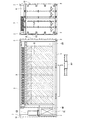
そして、本発明では、建造物の屋根の下方には中間天井板が設けられ、電子機器が中間天井板の下側の室内に収められるとともに、室内の空気を冷却する熱交換器と排熱用の室外熱交換器とが、それぞれ中間天井板の下方と上方とに設置される。この構造について、図5(a)(b)により説明する。
コンピュータ等の電子機器は、多数のものがラック6に収納される形で建造物の室内に収められ、ラック6は、床面に敷設されたT形板材7上に固定されて(詳細な構造については後述)、コンピュータ室CRの横断面においてほぼ中央部に設置される。各々のラック6の上方には、コンピュータ室CRの室内の空気を冷却する熱交換器8を収めた熱交換器外箱81が取り付けられており、ラック6と熱交換器8とは、ユニット化されたラック−熱交換器組立体を構成している。この実施例では、コンピュータ室CR内には8個のラック−熱交換器組立体が設置され(図1)、ラックの上方の熱交換器は、主に組み合わされた下方のラックを独立して冷却するための熱交換器となっている。
In the present invention, an intermediate ceiling plate is provided below the roof of the building, and an electronic device is housed in a room below the intermediate ceiling plate, and a heat exchanger that cools indoor air and exhaust heat The outdoor heat exchangers are respectively installed below and above the intermediate ceiling plate. This structure will be described with reference to FIGS.
A large number of electronic devices such as computers are housed in a building room in such a manner that they are housed in a
ラック−熱交換器組立体と建造物の屋根との間には中間天井板9が設けてあり、この部分では、建造物は2重天井を形成している。この実施例では、中間天井板9は、断熱材の積層された断熱パネルであって、その端部は、建造物の長手方向の全長に亘って延びるセンタービーム10に結合される。センタービーム10は、建造物の屋根3と中間天井板9とを連結しており、これによって、建造物の上部の強度並びに剛性を高めている。また、ラック6の強度及び耐震性を増大させるため、ラック−熱交換器組立体の上部は中間天井板9に固定される。
An
コンピュータ室CRの空気を冷却するための、ラック6と組み合わされた熱交換器8の上方には、室外熱交換器11が置かれ、これは、コンピュータ室CRの室外となる中間天井板9の上部に載置される。両方の熱交換器は、特許文献2に記載された熱交換装置のように、互いに連通され、内部には気体−液体の相変化を行う冷媒が封入されている。室内側の熱交換器8の端部には、コンピュータ室CR内の空気を循環するファン12が装着されるとともに、室外熱交換器11の端部には、外気を導入するファン13が装着される。ファン13により導入された外気は、室外熱交換器11を冷却した後、直角に曲げられて建造物の長手方向に延びる共通排気ダクト14を通過し、建造物の前端上部又は後端上部の流出口から排出される。外気の流れを逆向きとして、ファン13から排出するようにしてもよい。
図5(b)に示されるとおり、ラック6に収納されたコンピュータの発熱に伴い、温度の上昇した室内の空気は、図の左側矢印のように、コンピュータ室CR内を上昇して熱交換器8に導入され、内部に封入された液体の冷媒を沸騰させる。気体となった冷媒は、対流によって室外熱交換器11に入り、ここで熱を外気に放熱して凝縮し、温度が低下した状態で室内の熱交換器8に還流する。一方、熱交換器8で冷却された室内の空気は、冷却空気を循環するファン12によって図の右側矢印のように送り出され、ラック6に収納されたコンピュータを冷却することとなる。
Above the
As shown in FIG. 5B, the indoor air whose temperature has risen as the computer stored in the
上述のとおり、この実施例における室内空気の冷却装置は、対流により循環する冷媒を封入した2個の熱交換器を設け、密閉した室内の熱を排熱する自然冷却式のものであり、基本的に電力を使用することなく冷却を行うことができる。ただし、室内の空気を冷却するため、圧縮機等を装備して冷凍サイクルを実行させ、冷凍サイクルのエバポレータ(蒸発器)を、熱交換器として室内に設置してもよい。この実施例においても、外気温が上昇して自然冷却式の冷却装置の冷却能力が不足するなどの事態に備えて、冷凍サイクルを実行する予備の空調機が設置されており、そのエバポレータEV(図5(a))が天井面に装着されるとともに、圧縮機やコンデンサ(凝縮器)を収めた室外機CD(図1)が機械室の上部に据え付けられている。 As described above, the indoor air cooling apparatus in this embodiment is of a natural cooling type in which two heat exchangers enclosing a refrigerant circulating by convection are provided, and the heat in the sealed room is exhausted. Therefore, cooling can be performed without using electric power. However, in order to cool indoor air, a refrigeration cycle may be executed by installing a compressor or the like, and an evaporator (evaporator) of the refrigeration cycle may be installed indoors as a heat exchanger. Also in this embodiment, in preparation for a situation where the outside air temperature rises and the cooling capacity of the natural cooling type cooling device is insufficient, a spare air conditioner for executing the refrigeration cycle is installed, and the evaporator EV ( 5A) is mounted on the ceiling surface, and an outdoor unit CD (FIG. 1) containing a compressor and a condenser (condenser) is installed at the upper part of the machine room.
次いで、ラック6が設置される、本発明の建造物の床構造について、図6に基づき説明を加える。建造物の底部は、輸送用のコンテナと同様に、長方形をなす枠体に、長手方向と直角(横方向)に延びる複数のクロスメンバ51を適宜の間隔で掛け渡した底部フレーム5を備えており、底部フレーム5を横断するフォークポケットFPが2個所に取り付けられる。クロスメンバ51の上方には、発泡合成樹脂等の断熱材の両面にアルミニウム等の金属板を積層したサンドイッチパネル15が、建造物の床のほぼ全面に設置され、さらにその上方に、連続して延びるT形断面形状の突起161を、底板上に複数並列して形成したT形板材16が敷設される。
Next, the floor structure of the building of the present invention in which the
T形板材16は、いわゆるT形ボードと呼ばれる長尺のアルミニウム押出し形材が使用され、図6(a)に示されるように、機械室の床面まで建造物のほぼ全長に亘って敷設されている。T形板材16を敷設しない部分には、図6(b)に示されるとおり、ハット形断面形状のハット形板材17が敷設されており、ここに浅皿形の空間が形成される。ハット形板材17の上部を含め、ラック6が載置される個所以外の部分は、図示しない薄板のカバーによって覆われる。
この床構造においては、T形板材16の突起161の間の空間、ハット形板材17の空間を利用して、ラック6に収納されたコンピュータへの自由なケーブルの配線が可能である。また、ファン12により室内を循環する冷却空気は、これらの空間を通過してラック6の周囲や下部へ流れ込む。そのため、コンピュータ等から発生する熱が効率的に除去され、温度上昇による熱障害が防止される。
As the T-shaped
In this floor structure, the cable between the
以上詳述したように、本発明は、電子機器を収めた建造物において、その4隅に配置した柱状部材の上部及び下部に緊締具の係合可能な締結金具を固着し、建造物の屋根の下方には中間天井板を設け、電子機器を中間天井板の下側室内に収め、かつ、中間天井板を挟むように電子機器の冷却装置を配置するものである。上記の実施例では、電子機器の冷却のため、自然対流循環型の熱交換器を用いた外気冷却方式を利用しているが、これに代えて、冷凍サイクルを実行する空調機を採用し、その室外機を中間天井板の上部に設置してもよい。また、実施例では、夫々のラックの上方に独立した冷却装置を設置しているが、室内を集中して冷却する1個の冷却装置を設けるなど、実施例に対し種々の変形が可能であるのは明らかである。 As described above in detail, in the present invention, in a building containing electronic equipment, fasteners capable of engaging fasteners are fixed to the upper and lower portions of columnar members arranged at the four corners of the building so that the roof of the building is secured. An intermediate ceiling plate is provided below, an electronic device is placed in a lower chamber of the intermediate ceiling plate, and a cooling device for the electronic device is disposed so as to sandwich the intermediate ceiling plate. In the above embodiment, an external air cooling method using a natural convection circulation type heat exchanger is used for cooling the electronic device, but instead, an air conditioner that executes a refrigeration cycle is adopted, The outdoor unit may be installed above the intermediate ceiling plate. In the embodiment, an independent cooling device is installed above each rack. However, various modifications can be made to the embodiment, such as providing a single cooling device that cools the room in a concentrated manner. It is clear.
1 柱状部材
1F 前部側柱状部材、 1R 後部側柱状部材
2 締結金具
3 屋根
4 梁部材
5 底部フレーム
6 ラック
8 熱交換器(室内空気冷却用)
9 中間天井板
11 室外熱交換器
12 ファン(室内空気循環用)
16 T形板材
DESCRIPTION OF SYMBOLS 1
9
16 T-shaped board
Claims (6)
前記建造物は、平面視で長方形の形状を有し、その長方形の4隅には柱状部材が配置されるとともに、各々の前記柱状部材の上部及び下部には、緊締具の係合可能な締結金具が固着され、
前記建造物の屋根は、上部に固着された前記締結金具よりも低くなる位置に設置されており、さらに、
前記建造物の屋根の下方には中間天井板が設けられ、前記電子機器が前記中間天井板の下側に形成される室内に収められており、
前記中間天井板の下側に形成される室内には、室内の空気を冷却する熱交換器と冷却された空気を循環するファンとが設けられ、かつ、前記建造物の屋根と前記中間天井板との間には、前記熱交換器が吸収した熱を外気に排熱する室外熱交換器が設置されることを特徴とする建造物。 A building that houses electronic equipment in a room,
The building has a rectangular shape in plan view, and columnar members are arranged at four corners of the rectangle, and fasteners that can be engaged with fasteners are provided at the upper and lower portions of the columnar members. The bracket is fixed,
The roof of the building is installed at a position that is lower than the fasteners secured to the top, and
An intermediate ceiling plate is provided below the roof of the building, and the electronic device is housed in a room formed below the intermediate ceiling plate,
The room formed below the intermediate ceiling plate is provided with a heat exchanger for cooling indoor air and a fan for circulating the cooled air, and the roof of the building and the intermediate ceiling plate Between, the outdoor heat exchanger which exhausts the heat | fever which the said heat exchanger absorbed to the outside air is installed, The building characterized by the above-mentioned.
Priority Applications (1)
| Application Number | Priority Date | Filing Date | Title |
|---|---|---|---|
| JP2011126424A JP5419926B2 (en) | 2011-06-06 | 2011-06-06 | A simple building with electronic equipment |
Applications Claiming Priority (1)
| Application Number | Priority Date | Filing Date | Title |
|---|---|---|---|
| JP2011126424A JP5419926B2 (en) | 2011-06-06 | 2011-06-06 | A simple building with electronic equipment |
Publications (2)
| Publication Number | Publication Date |
|---|---|
| JP2012252639A JP2012252639A (en) | 2012-12-20 |
| JP5419926B2 true JP5419926B2 (en) | 2014-02-19 |
Family
ID=47525366
Family Applications (1)
| Application Number | Title | Priority Date | Filing Date |
|---|---|---|---|
| JP2011126424A Expired - Fee Related JP5419926B2 (en) | 2011-06-06 | 2011-06-06 | A simple building with electronic equipment |
Country Status (1)
| Country | Link |
|---|---|
| JP (1) | JP5419926B2 (en) |
Families Citing this family (4)
| Publication number | Priority date | Publication date | Assignee | Title |
|---|---|---|---|---|
| WO2014174606A1 (en) * | 2013-04-24 | 2014-10-30 | 株式会社日立システムズ | Container-type data center |
| US9345174B2 (en) | 2013-04-24 | 2016-05-17 | Hitachi Systems, Ltd. | Container-type data center having air conditioning facility |
| WO2015121994A1 (en) * | 2014-02-14 | 2015-08-20 | 株式会社日立製作所 | Electronic-apparatus cooling device and case for cooling |
| JP2020021386A (en) * | 2018-08-03 | 2020-02-06 | 清水建設株式会社 | Server room air conditioning system, and data center |
Family Cites Families (8)
| Publication number | Priority date | Publication date | Assignee | Title |
|---|---|---|---|---|
| JPH04230099A (en) * | 1990-12-27 | 1992-08-19 | Furukawa Electric Co Ltd:The | Heat-pipe type enclosure cooler |
| CN101501599B (en) * | 2006-06-01 | 2011-12-21 | 谷歌公司 | Modular computing environments |
| US7430118B1 (en) * | 2007-06-04 | 2008-09-30 | Yahoo! Inc. | Cold row encapsulation for server farm cooling system |
| JP2009063226A (en) * | 2007-09-06 | 2009-03-26 | Caterpillar Japan Ltd | Structure of computer lab |
| WO2010039120A1 (en) * | 2008-09-30 | 2010-04-08 | Hewlett-Packard Development Company, L.P. | Data center |
| US7990710B2 (en) * | 2008-12-31 | 2011-08-02 | Vs Acquisition Co. Llc | Data center |
| JP5478185B2 (en) * | 2009-10-06 | 2014-04-23 | 高砂熱学工業株式会社 | Air conditioning system |
| US8233270B2 (en) * | 2009-11-20 | 2012-07-31 | Turbine Air Systems, Ltd. | Modular data center |
-
2011
- 2011-06-06 JP JP2011126424A patent/JP5419926B2/en not_active Expired - Fee Related
Also Published As
| Publication number | Publication date |
|---|---|
| JP2012252639A (en) | 2012-12-20 |
Similar Documents
| Publication | Publication Date | Title |
|---|---|---|
| JP5762646B2 (en) | Container type data center | |
| US9345174B2 (en) | Container-type data center having air conditioning facility | |
| JP5762645B2 (en) | Container type data center | |
| JP5419926B2 (en) | A simple building with electronic equipment | |
| US20070175236A1 (en) | Portable refrigeration container | |
| AU2012345182B2 (en) | Outdoor machine for an air-conditioning device | |
| CN111194154B (en) | Rack structure for data center | |
| JP5545675B2 (en) | Ceiling structure of a simple building containing electronic equipment | |
| JP2014048816A (en) | Air conditioning system of building with electronic equipment housed therein | |
| JP5814001B2 (en) | Electronic equipment container | |
| WO2015045252A1 (en) | Refrigeration device for container | |
| JP5618909B2 (en) | Building with electronic equipment | |
| TWI568639B (en) | Equipment for the installation of refrigerators for foodstuffs on ships and for the installation of refrigerators on ships | |
| WO2021024406A1 (en) | Chilling unit and chilling unit system | |
| JP2012167862A (en) | Outdoor unit of refrigerating apparatus | |
| JP5723682B2 (en) | Electronic equipment container | |
| WO2014174608A1 (en) | Container-type data center | |
| CN220392115U (en) | Container | |
| WO2020076320A1 (en) | Systems and methods for mechanical load isolation in transportable storage container | |
| JPH11294928A (en) | Cold retention box | |
| US11272637B2 (en) | Rack arrangement for a data center | |
| US20230069508A1 (en) | Rack system for a data center | |
| CN115101877A (en) | Make things convenient for battery box of battery module dismouting | |
| CN116018478A (en) | Outdoor unit of air conditioner | |
| JP2010255876A (en) | Heat exchange device and heating element storage device using the same |
Legal Events
| Date | Code | Title | Description |
|---|---|---|---|
| A621 | Written request for application examination |
Free format text: JAPANESE INTERMEDIATE CODE: A621 Effective date: 20130313 |
|
| A977 | Report on retrieval |
Free format text: JAPANESE INTERMEDIATE CODE: A971007 Effective date: 20131030 |
|
| TRDD | Decision of grant or rejection written | ||
| A01 | Written decision to grant a patent or to grant a registration (utility model) |
Free format text: JAPANESE INTERMEDIATE CODE: A01 Effective date: 20131119 |
|
| A977 | Report on retrieval |
Free format text: JAPANESE INTERMEDIATE CODE: A971007 Effective date: 20131125 |
|
| A61 | First payment of annual fees (during grant procedure) |
Free format text: JAPANESE INTERMEDIATE CODE: A61 Effective date: 20131119 |
|
| R150 | Certificate of patent or registration of utility model |
Ref document number: 5419926 Country of ref document: JP Free format text: JAPANESE INTERMEDIATE CODE: R150 |
|
| LAPS | Cancellation because of no payment of annual fees |