JP5415735B2 - Dressing method, dressing condition determining method, dressing condition determining program, and polishing apparatus - Google Patents
Dressing method, dressing condition determining method, dressing condition determining program, and polishing apparatus Download PDFInfo
- Publication number
- JP5415735B2 JP5415735B2 JP2008247450A JP2008247450A JP5415735B2 JP 5415735 B2 JP5415735 B2 JP 5415735B2 JP 2008247450 A JP2008247450 A JP 2008247450A JP 2008247450 A JP2008247450 A JP 2008247450A JP 5415735 B2 JP5415735 B2 JP 5415735B2
- Authority
- JP
- Japan
- Prior art keywords
- sliding distance
- dressing
- dresser
- polishing
- diamond dresser
- Prior art date
- Legal status (The legal status is an assumption and is not a legal conclusion. Google has not performed a legal analysis and makes no representation as to the accuracy of the status listed.)
- Active
Links
Images


Classifications
-
- B—PERFORMING OPERATIONS; TRANSPORTING
- B24—GRINDING; POLISHING
- B24B—MACHINES, DEVICES, OR PROCESSES FOR GRINDING OR POLISHING; DRESSING OR CONDITIONING OF ABRADING SURFACES; FEEDING OF GRINDING, POLISHING, OR LAPPING AGENTS
- B24B53/00—Devices or means for dressing or conditioning abrasive surfaces
- B24B53/017—Devices or means for dressing, cleaning or otherwise conditioning lapping tools
Description
本発明は、光学部品、機械部品、セラミックスおよび金属等などの研磨対象物を研磨する研磨装置に使用される研磨部材をダイヤモンドドレッサによってドレッシングするドレッシング方法、ドレッシング条件の決定方法、ドレッシング条件決定プログラム、および研磨装置に関し、特に半導体ウェーハ等の研磨対象物の表面を平坦に研磨する研磨装置の研磨パッドに好適なドレッシング方法、ドレッシング条件の決定方法、ドレッシング条件決定プログラム、および研磨装置に関する。 The present invention relates to a dressing method for dressing a polishing member used in a polishing apparatus for polishing a polishing object such as an optical component, a mechanical component, ceramics, metal, etc. with a diamond dresser, a dressing condition determining method, a dressing condition determining program, More particularly, the present invention relates to a dressing method suitable for a polishing pad of a polishing apparatus that flatly polishes the surface of an object to be polished such as a semiconductor wafer, a dressing condition determination method, a dressing condition determination program, and a polishing apparatus.
近年、半導体デバイスの高集積化が進むにつれて、回路の配線が微細化し、集積されるデバイスの寸法もより微細化されつつある。そこで、表面に例えば金属等の膜が形成された半導体ウェーハを研磨して、半導体ウェーハの表面を平坦化する工程が必要となっている。この平坦化法の一つとして、化学機械研磨(CMP)装置による研磨がある。化学機械研磨装置は、研磨部材(研磨布、研磨パッド等)と、半導体ウェーハ等の研磨対象物を保持する保持部(トップリング、研磨ヘッド、チャック等)とを有している。そして、研磨対象物の表面(被研磨面)を研磨部材の表面に押当て、研磨部材と研磨対象物との間に研磨助剤(砥液、薬液、スラリー、純水等)を供給しつつ、研磨部材と研磨対象物とを相対運動させることにより、研磨対象物の表面を平坦に研磨するようにしている。化学機械研磨装置による研磨では、化学的研磨作用と機械的研磨作用により、良好な研磨が行われることが知られている。 In recent years, with the progress of high integration of semiconductor devices, circuit wiring has been miniaturized, and the dimensions of the integrated devices are being further miniaturized. Therefore, it is necessary to polish a semiconductor wafer having a film made of metal or the like on the surface to flatten the surface of the semiconductor wafer. As one of the planarization methods, there is polishing by a chemical mechanical polishing (CMP) apparatus. The chemical mechanical polishing apparatus includes a polishing member (polishing cloth, polishing pad, etc.) and a holding unit (top ring, polishing head, chuck, etc.) that holds an object to be polished such as a semiconductor wafer. Then, the surface of the polishing object (surface to be polished) is pressed against the surface of the polishing member, and a polishing aid (abrasive solution, chemical solution, slurry, pure water, etc.) is supplied between the polishing member and the polishing object. The surface of the polishing object is flatly polished by relatively moving the polishing member and the polishing object. It is known that in the polishing by the chemical mechanical polishing apparatus, good polishing is performed by the chemical polishing action and the mechanical polishing action.
この様な化学機械研磨装置に用いられる研磨部材の材料(素材)としては、一般に発泡樹脂や不織布が用いられている。研磨部材の表面には微細な凹凸が形成されており、この微細な凹凸は、目詰まり防止や研磨抵抗の低減に効果的なチップポケットとして作用する。しかし、研磨部材で研磨対象物の研磨を続けると、研磨部材表面の微細な凹凸が潰れてしまい、研磨レートの低下を引き起こす。このため、多数のダイヤモンド粒子を電着させたダイヤモンドドレッサで研磨部材表面のドレッシング(目立て)を行い、研磨部材表面に微細な凹凸を再形成する。 As a material (raw material) of a polishing member used in such a chemical mechanical polishing apparatus, a foamed resin or a nonwoven fabric is generally used. Fine irregularities are formed on the surface of the polishing member, and the minute irregularities act as chip pockets effective for preventing clogging and reducing polishing resistance. However, if polishing of the object to be polished is continued with the polishing member, fine irregularities on the surface of the polishing member are crushed, causing a reduction in the polishing rate. Therefore, dressing (sharpening) the surface of the polishing member is performed with a diamond dresser in which a large number of diamond particles are electrodeposited, and fine irregularities are re-formed on the surface of the polishing member.
研磨部材のドレッシング方法としては、研磨部材の研磨で使用される領域と同等かそれよりも大きいドレッサ(大径ドレッサ)を使用する方法や、研磨部材の研磨で使用される領域よりも小さいドレッサ(小径ドレッサ)を使用する方法がある。大径ドレッサを使用する場合、例えばドレッサの位置を固定してドレッサを回転させながら、ダイヤモンド粒子が電着されているドレッシング面を回転している研磨部材に押し付けてドレッシングする。小径ドレッサを使用する場合、例えば回転するドレッサを移動(円弧状や直線状に往復運動、揺動)させながら、ドレッシング面を回転している研磨部材に押し付けてドレッシングする。なおこのように研磨部材を回転させながらドレッシングする場合、研磨部材の全表面のうち実際に研磨のために使用される領域は研磨部材の回転中心を中心とする円環形状の領域である。 As a dressing method of the polishing member, a method using a dresser (large diameter dresser) equal to or larger than a region used for polishing the polishing member, or a dresser (smaller than a region used for polishing the polishing member) There is a method using a small diameter dresser). When a large diameter dresser is used, for example, the dressing surface on which the diamond particles are electrodeposited is pressed against the rotating polishing member while performing dressing while fixing the position of the dresser and rotating the dresser. When using a small-sized dresser, for example, the dressing surface is pressed against the rotating polishing member while dressing the rotating dresser while moving (reciprocating or swinging in a circular or linear shape). When dressing while rotating the polishing member in this way, the region actually used for polishing of the entire surface of the polishing member is an annular region centering on the rotation center of the polishing member.
ここで、研磨部材のドレッシングの際に、微量ではあるが研磨部材の表面が削り取られる。したがって、適切にドレッシングが行われないと研磨部材の表面に不適切なうねりが生じ、被研磨面内で研磨レートのばらつきが生じるという不都合がある。研磨レートのばらつきは、研磨不良の原因となるため、研磨部材の表面に不適切なうねりを生じさせないようなドレッシングを行う必要がある。即ち、研磨部材の適切な回転速度、ドレッサの適切な回転速度、適切なドレッシング荷重、小径ドレッサの場合はドレッサの適切な移動速度といった、適切なドレッシング条件でドレッシングを行うことで研磨レートのばらつきを回避している。 Here, at the time of dressing the polishing member, the surface of the polishing member is scraped off even though the amount is small. Therefore, if dressing is not performed appropriately, the surface of the polishing member will be improperly undulated and there will be a disadvantage that the polishing rate will vary within the surface to be polished. Variations in the polishing rate cause poor polishing, and it is necessary to perform dressing that does not cause inappropriate undulations on the surface of the polishing member. That is, dispersion of the polishing rate is achieved by performing dressing under appropriate dressing conditions such as an appropriate rotation speed of the polishing member, an appropriate rotation speed of the dresser, an appropriate dressing load, and an appropriate moving speed of the dresser in the case of a small-diameter dresser. It is avoiding.
研磨部材の回転速度、ドレッサの回転速度、ドレッシング荷重、ドレッサの移動速度は互いに独立に制御することができるものの、これらの要素が研磨部材の削れ量に与える影響は複雑である。特に、小径ドレッサによるドレッシングにおいてはドレッシング条件を実験的に決定するには多くの時間と労力が必要となる。そこで、シミュレーションによるドレッシング条件の決定方法が提案されている。 Although the rotation speed of the polishing member, the rotation speed of the dresser, the dressing load, and the movement speed of the dresser can be controlled independently of each other, the influence of these factors on the amount of abrasion of the polishing member is complicated. In particular, in dressing with a small diameter dresser, much time and labor are required to experimentally determine dressing conditions. Therefore, a method for determining dressing conditions by simulation has been proposed.
例えば、特許文献1には、研磨布上の各点におけるドレッサ砥石の摺動距離がドレッシング量(ドレッサ砥石による研磨布の削れ量)と密接な関係にあることを利用して、ドレッサ砥石の摺動距離分布を求め、ドレッサ砥石の移動条件を最適化する方法が提案されている。 For example, Patent Document 1 discloses that the sliding distance of the dresser grindstone at each point on the polishing cloth is closely related to the dressing amount (the amount of abrasion of the polishing cloth by the dresser grindstone). There has been proposed a method for obtaining a moving distance distribution and optimizing the moving condition of the dresser grindstone.
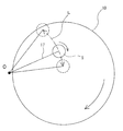
しかし、ダイヤモンドドレッサの摺動距離分布のシミュレーション結果と研磨パッド削れ量分布の測定結果を比較すると、必ずしも精度良くシミュレーションできているとはいえない。図1は、小径ドレッサ5によって研磨部材の一種である研磨パッド10をドレッシングする際の、ドレッサ5の揺動範囲の一例を示した図である。ドレッサアーム17は、ドレッサ揺動軸Oを中心にして揺動し、ドレッサアーム17の揺動により、ドレッサ5は円弧Lで示す範囲で揺動する。図2は、あるドレッシング条件で、図1のような小径ドレッサを揺動させてドレッシングした際の研磨パッド削れ量の測定結果と、公知の方法による摺動距離のシミュレーション結果をそれぞれの平均値で除して規格化した値の研磨パッド半径方向の分布を示すグラフである。
However, if the simulation result of the sliding distance distribution of the diamond dresser is compared with the measurement result of the polishing pad scraping amount distribution, it cannot be said that the simulation can be performed with high accuracy. FIG. 1 is a view showing an example of a swing range of the
研磨パッド削れ量と摺動距離とを定性的に比較してみると、研磨パッドの中心(研磨パッド半径が0)から研磨パッド半径が100mm程度の部分までは、研磨パッド半径が大きくなるにしたがって、研磨パッド削れ量および摺動距離ともに大きくなり、研磨パッド半径120mm付近で両者とも小さくなり、研磨パッド半径120mmを超えるとまた両者とも大きくなり、研磨パッド半径250mm付近でまた両者とも小さくなり、研磨パッド半径250mmを超えると両者とも大きくなっており、両者が密接な関係にあることに疑いの余地はない。なお、本明細書で摺動距離とは、ドレッサと研磨パッド(研磨部材)とが接触しながら相対移動したときの研磨パッド上の各点におけるドレッサの移動距離のことであり、具体的には研磨パッド上の各点をドレッシング面(すなわちドレッサのダイヤモンド粒子が配置された面)が通過したときの相対速度を時間で積分したものである。 Comparing the polishing pad scraping amount and the sliding distance qualitatively, from the center of the polishing pad (polishing pad radius is 0) to the portion where the polishing pad radius is about 100 mm, the polishing pad radius increases. The polishing pad scraping amount and sliding distance both increase, both decrease near the polishing pad radius of 120 mm, increase both when the polishing pad radius exceeds 120 mm, and decrease both near the polishing pad radius of 250 mm. When the pad radius exceeds 250 mm, both of them become large, and there is no doubt that they are in a close relationship. In the present specification, the sliding distance is a movement distance of the dresser at each point on the polishing pad when the dresser and the polishing pad (polishing member) move relative to each other while being in contact. It is the result of integrating the relative speed with time when the dressing surface (that is, the surface on which the dresser diamond particles are disposed) passes through each point on the polishing pad.
しかし、公知の方法では、図2に示すように、研磨パッド削れ量の実験結果に比べて、摺動距離のシミュレーション結果の起伏が激しい。即ち、摺動距離分布によってドレッシング量(研磨パッドの削れ量)分布が適切にシュミレーションされていると言うためには、実験結果とシミュレーション結果の分布形状が互いにほぼ相似でなければならない。換言すれば、例えば図2において、研磨パッド半径に対する研磨パッド削れ量の分布形状と摺動距離の分布形状とが互いに似ている(または互いに比例的関係にある)必要があるが、上記のように両者の分布形状にかなりの相違がある。従って公知の方法による摺動距離のシミュレーション結果を用いて所望の研磨パッド削れ量となるようにドレッシング条件を決定すると、実際の研磨パッド削れ量は所望の削れ量との間で差が大きく開いてしまう。そのため、所望の研磨パッド削れ量分布が得られるドレッシング条件を見出すには更なる実験的検討が必要であった。 However, in the known method, as shown in FIG. 2, the undulation of the simulation result of the sliding distance is more severe than the experimental result of the polishing pad scraping amount. That is, in order to say that the dressing amount (polishing amount of polishing pad) distribution is appropriately simulated by the sliding distance distribution, the distribution shapes of the experimental result and the simulation result must be substantially similar to each other. In other words, in FIG. 2, for example, the distribution shape of the polishing pad scraping amount with respect to the polishing pad radius and the distribution shape of the sliding distance need to be similar to each other (or are in a proportional relationship with each other). However, there is a considerable difference in the distribution shape between the two. Therefore, if the dressing conditions are determined so that the desired polishing pad scraping amount is obtained using the simulation result of the sliding distance by a known method, the actual polishing pad scraping amount is greatly different from the desired scraping amount. End up. Therefore, further experimental investigation is necessary to find out the dressing conditions that can provide the desired polishing pad wear distribution.
また、図2において、実験およびシミュレーションのドレッシング条件は、研磨パッドの外縁からダイヤモンドドレッサの一部がはみ出すような条件である。この場合、ダイヤモンドドレッサのドレッシング荷重(ダイヤモンドドレッサを研磨パッドに押し付ける荷重)は一定でありながら、ダイヤモンドドレッサの一部がはみ出すため、ドレッサと研磨パッドとの接触面積が小さくなり、ドレッサが研磨パッドを押し付ける圧力(ドレッシング圧力)は大きくなる。ドレッシング圧力が大きくなると、ドレッシング圧力に略比例して研磨パッドの削れ量が大きくなることが予想される。図2の摺動距離シミュレーションにおいては、このドレッシング圧力の増加を、摺動距離に補正係数を掛けることによって補正している。しかし、図2に見られるように、ダイヤモンドドレッサが研磨パッドからはみ出す研磨パッドの外周部では、研磨パッド削れ量と摺動距離のシミュレーション結果との差が非常に大きい。 In FIG. 2, the dressing conditions for the experiment and simulation are such that part of the diamond dresser protrudes from the outer edge of the polishing pad. In this case, the dressing load of the diamond dresser (the load that presses the diamond dresser against the polishing pad) is constant, but part of the diamond dresser protrudes, so the contact area between the dresser and the polishing pad decreases, and the dresser pushes the polishing pad. The pressing pressure (dressing pressure) increases. As the dressing pressure increases, it is expected that the amount of abrasion of the polishing pad increases in proportion to the dressing pressure. In the sliding distance simulation of FIG. 2, this increase in dressing pressure is corrected by multiplying the sliding distance by a correction coefficient. However, as seen in FIG. 2, the difference between the polishing pad scraping amount and the sliding distance simulation result is very large at the outer periphery of the polishing pad where the diamond dresser protrudes from the polishing pad.
研磨に使用される領域が研磨パッドの外縁近くにまでおよぶ場合には、研磨パッドを外縁まで適切にドレッシングする必要がある。しかしながら、上記の通り研磨パッド外周部における実際の研磨パッド削れ量と摺動距離のシミュレーション結果との差が大きい。したがって、所望の研磨パッド削れ量分布が得られるドレッシング条件を見出すには更なる実験的検討が必要であった。 If the area used for polishing extends close to the outer edge of the polishing pad, it is necessary to dress the polishing pad appropriately to the outer edge. However, as described above, the difference between the actual polishing pad scraping amount and the sliding distance simulation result at the outer periphery of the polishing pad is large. Therefore, further experimental investigation is necessary to find out the dressing conditions for obtaining the desired polishing pad scraping distribution.
また、半導体デバイスの微細化に伴って、研磨レートばらつきの許容範囲が小さくなっており、研磨レートばらつきに影響する研磨パッドの削れ量分布の適切な制御が重要になってきている。したがって、より精度の高いシミュレーションを用いてドレッシング条件を決めることが必要となっている。 Further, with the miniaturization of semiconductor devices, the allowable range of the polishing rate variation is becoming smaller, and appropriate control of the polishing pad scraping distribution that affects the polishing rate variation has become important. Therefore, it is necessary to determine dressing conditions using a more accurate simulation.
本発明は、上記事情に鑑みて為されたもので、従来よりも精度の高いシミュレーションを用いてドレッシング条件を決定することにより、予測した削れ量に十分に近い削れ量で研磨部材をドレッシングすることができる方法を提供することを目的とする。また、本発明は、該ドレッシング条件の決定方法、ドレッシング条件決定プログラム、および該ドレッシング方法を実行することができる研磨装置を提供することを目的とする。 The present invention has been made in view of the above circumstances, and dressing a polishing member with a scraping amount sufficiently close to the predicted scraping amount by determining dressing conditions using a simulation with higher accuracy than conventional. An object is to provide a method capable of Another object of the present invention is to provide a dressing condition determination method, a dressing condition determination program, and a polishing apparatus capable of executing the dressing method.
上述の目的を達成するために鋭意研究した結果、発明者らは以下に説明するように、ダイヤモンドドレッサ表面に配置されたダイヤモンドの研磨部材への食い込みを考慮して摺動距離をシミュレーションすることによって、従来よりも精度の高いシミュレーション結果が得られることを突き止めた。また、ダイヤモンドドレッサとその回転駆動軸との間のなす角度が可変となるように構成した場合には、ダイヤモンドドレッサの一部が研磨部材の外縁からはみ出した際のダイヤモンドドレッサの傾きを考慮して摺動距離をシミュレーションすることによって、研磨部材外周部におけるシミュレーション精度が向上することを突き止めた。更に、精度の高いシミュレーションを用いて決定したドレッシング条件で研磨部材をドレッシングすることにより、所望の削れ量分布で研磨部材をドレッシングできることを突き止めた。 As a result of diligent research to achieve the above-mentioned object, the inventors have simulated the sliding distance in consideration of the biting of the diamond disposed on the diamond dresser surface into the abrasive member, as will be described below. It has been found that simulation results with higher accuracy than before can be obtained. In addition, when the angle between the diamond dresser and the rotational drive shaft is made variable, the inclination of the diamond dresser when a part of the diamond dresser protrudes from the outer edge of the polishing member is taken into account. By simulating the sliding distance, it was found that the simulation accuracy in the outer peripheral portion of the polishing member was improved. Furthermore, it was found that the polishing member can be dressed with a desired wear distribution by dressing the polishing member under dressing conditions determined using a highly accurate simulation.
本発明の一態様は、研磨部材表面でのダイヤモンドドレッサの摺動距離分布をシミュレーションすることにより決定されるドレッシング条件で前記研磨部材をドレッシングするドレッシング方法であって、前記シミュレーションが、前記ダイヤモンドドレッサ表面に配置されたダイヤモンド粒子の前記研磨部材への食い込み深さが大きい所では前記ダイヤモンドドレッサの摺動距離が大きくなるように、前記食い込み深さが小さい所では前記摺動距離が小さくなるように補正された摺動距離を計算する工程を含むシミュレーションであることを特徴とするドレッシング方法を提供する。 One aspect of the present invention is a dressing method for dressing the abrasive member under dressing conditions determined by simulating the sliding distance distribution of the diamond dresser on the surface of the abrasive member, wherein the simulation comprises the surface of the diamond dresser. Correction is made so that the sliding distance of the diamond dresser is increased when the depth of penetration of the diamond particles arranged on the polishing member is large, and the sliding distance is decreased when the depth of penetration is small. There is provided a dressing method characterized by being a simulation including a step of calculating a calculated sliding distance.
ダイヤモンド粒子の研磨部材への食い込みを考慮して摺動距離をシミュレーションすることによって、従来よりも精度の高いシミュレーション結果が得られ、このシミュレーションを用いて決定されるドレッシング条件で研磨部材をドレッシングすることにより、所望の削れ量分布で研磨部材をドレッシングすることができる。 By simulating the sliding distance in consideration of the penetration of diamond particles into the abrasive member, a more accurate simulation result than before can be obtained, and dressing the abrasive member under the dressing conditions determined using this simulation Thus, it is possible to dress the polishing member with a desired wear amount distribution.
本発明の好ましい態様は、前記シミュレーションが、前記ダイヤモンドドレッサが前記研磨部材からはみ出したときの前記ダイヤモンドドレッサの傾きに応じて更に補正された摺動距離を計算する工程を含むシミュレーションであることを特徴とするドレッシング方法を提供する。 In a preferred aspect of the present invention, the simulation is a simulation including a step of calculating a sliding distance further corrected in accordance with an inclination of the diamond dresser when the diamond dresser protrudes from the polishing member. A dressing method is provided.
これにより、研磨部材外周部におけるシミュレーション精度が更に向上し、このシミュレーションを用いて決定されるドレッシング条件で研磨部材をドレッシングすることにより、研磨部材外周部においても所望の削れ量分布で研磨部材をドレッシングすることができる。特に、ドレッサがドレッサ回転軸に傾動自在に連結されている場合に、本発明は有効である。 This further improves the simulation accuracy at the outer periphery of the polishing member. By dressing the polishing member under the dressing conditions determined using this simulation, the polishing member can be dressed with the desired amount of wear distribution at the outer periphery of the polishing member. can do. In particular, the present invention is effective when the dresser is tiltably coupled to the dresser rotation shaft.
本発明の好ましい態様は、前記シミュレーションが、前記ダイヤモンドドレッサの移動の加速度に応じて摺動距離を計算する工程を含むシミュレーションであることを特徴とするドレッシング方法を提供する。 According to a preferred aspect of the present invention, there is provided a dressing method, wherein the simulation is a simulation including a step of calculating a sliding distance in accordance with an acceleration of movement of the diamond dresser.
ダイヤモンドドレッサが研磨部材上を移動(例えば揺動)する際、常に一定の速度で移動しているわけではなく、往復運動の折り返しに伴う加速度や移動速度の変化に伴う加速度が生じる。このダイヤモンドドレッサの加速度を考慮することによりシミュレーション精度が更に向上し、このシミュレーションを用いて決定されるドレッシング条件で研磨部材をドレッシングすることにより、所望の削れ量分布で研磨部材をドレッシングすることができる。 When the diamond dresser moves (for example, swings) on the polishing member, the diamond dresser does not always move at a constant speed, but an acceleration accompanying the return of the reciprocating motion and an acceleration accompanying a change in the moving speed occur. Considering the acceleration of the diamond dresser, the simulation accuracy is further improved. By dressing the polishing member under the dressing conditions determined using this simulation, the polishing member can be dressed with a desired wear amount distribution. .
本発明の他の態様は、ダイヤモンドドレッサを用いた研磨部材のドレッシング方法であって、仮のドレッシング条件を用いて前記研磨部材表面での前記ダイヤモンドドレッサの摺動距離を計算するステップと、前記計算された摺動距離を前記ダイヤモンドドレッサ表面に配置されたダイヤモンド粒子の前記研磨部材への食い込み深さが大きい所では前記摺動距離が大きくなるように、前記食い込み深さが小さい所では前記摺動距離が小さくなるように補正するステップと、所望の摺動距離分布となるドレッシング条件を前記仮のドレッシング条件を変えることで探索するステップと、前記探索されたドレッシング条件で前記ダイヤモンドドレッサにより前記研磨部材をドレッシングするステップとを含むことを特徴とするドレッシング方法を提供する。 Another aspect of the present invention is a dressing method for an abrasive member using a diamond dresser, the step of calculating a sliding distance of the diamond dresser on the surface of the abrasive member using temporary dressing conditions, and the calculation The sliding distance is increased so that the sliding distance is increased at a location where the penetration depth of the diamond particles disposed on the surface of the diamond dresser is large, and the sliding operation is performed at a location where the penetration depth is small. A step of correcting the distance so as to decrease, a step of searching for dressing conditions that provide a desired sliding distance distribution by changing the temporary dressing conditions, and the polishing member by the diamond dresser under the searched dressing conditions. Dressing method comprising the steps of: Subjected to.
本発明によれば、ダイヤモンドドレッサの摺動距離分布の計算結果が所望の摺動距離分布となるようなドレッシング条件を当該条件を構成する要素(変数)の値を変えて探索する。その際に、ダイヤモンドドレッサ表面に配置されたダイヤモンド粒子の研磨部材への食い込み深さに応じて摺動距離を補正する。これによって、単に摺動距離分布を計算するよりも実際の研磨部材削れ量分布に近い摺動距離分布の計算結果が得られる。さらに、探索されたドレッシング条件で研磨部材をドレッシングすることにより、所望の削れ量分布またはそれに十分に近い削れ量分布で研磨部材をドレッシングすることができる。 According to the present invention, a dressing condition in which the calculation result of the sliding distance distribution of the diamond dresser becomes a desired sliding distance distribution is searched by changing the values of elements (variables) constituting the condition. At that time, the sliding distance is corrected according to the depth of penetration of the diamond particles arranged on the surface of the diamond dresser into the polishing member. Thus, a calculation result of the sliding distance distribution closer to the actual abrasive member scraping amount distribution can be obtained than simply calculating the sliding distance distribution. Furthermore, by dressing the abrasive member under the searched dressing conditions, the abrasive member can be dressed with a desired wear amount distribution or a wear amount distribution sufficiently close thereto.
本発明の好ましい態様は、前記補正された摺動距離を、前記ダイヤモンドドレッサが前記研磨部材からはみ出したときの前記ダイヤモンドドレッサの傾きに応じて補正するステップを更に含むことを特徴とするドレッシング方法を提供する。 In a preferred aspect of the present invention, the dressing method further includes a step of correcting the corrected sliding distance according to an inclination of the diamond dresser when the diamond dresser protrudes from the polishing member. provide.
これにより、研磨部材の外周部における計算精度が更に向上し、研磨部材外周部においても所望の削れ量分布またはそれに十分に近い削れ量分布で研磨部材をドレッシングすることができる。 As a result, the calculation accuracy in the outer peripheral portion of the polishing member is further improved, and the polishing member can be dressed with a desired wear amount distribution or a wear amount distribution sufficiently close to that in the outer peripheral portion of the polishing member.
本発明の好ましい態様は、前記摺動距離を計算するステップが、前記ダイヤモンドドレッサの移動の加速度に応じて摺動距離を計算するステップであることを特徴とする方法を提供する。 In a preferred aspect of the present invention, there is provided a method, wherein the step of calculating the sliding distance is a step of calculating a sliding distance in accordance with an acceleration of movement of the diamond dresser.
例えば研磨部材が回転運動する場合において、研磨部材の半径方向位置に応じてダイヤモンドドレッサの移動(例えば揺動)速度を変化させても良い。その場合にダイヤモンドドレッサの加速度を実際にダイヤモンドドレッサにおいて実現可能な有限の値に設定し、研磨部材の半径方向位置に応じた移動速度を求めて、研磨部材上の各点におけるダイヤモンドドレッサの摺動距離を計算することにより、実際の研磨部材削れ量分布に近い摺動距離分布の計算結果が得られる。換言すれば、例えば研磨部材の半径方向において区画された領域1と領域2とを想定した場合、ダイヤモンドドレッサの移動速度が両領域で異なるケースにおいて、ダイヤモンドドレッサの移動速度を両領域で不連続に変化させるのではなく、領域1と領域2との間に適当な半径方向寸法を有する移行領域を画定し、ここにおいて(正または負の)有限な値の加速度を設定して、移動速度の値を一方の領域での値から他方の領域での値に連続的に変化させる。従って領域1と領域2との境界近傍に画定された前記移行領域においては、設定された加速度に応じて摺動距離が計算される。このようにして探索されたドレッシング条件で研磨部材をドレッシングすることにより、所望の削れ量分布により近い削れ量分布で研磨部材をドレッシングすることができる。
For example, when the polishing member rotates, the moving (for example, swinging) speed of the diamond dresser may be changed according to the radial position of the polishing member. In that case, the acceleration of the diamond dresser is set to a finite value that can be actually realized in the diamond dresser, and the moving speed according to the radial position of the abrasive member is obtained to slide the diamond dresser at each point on the abrasive member. By calculating the distance, the calculation result of the sliding distance distribution close to the actual abrasive member scraping amount distribution can be obtained. In other words, for example, when assuming the region 1 and the
本発明の他の態様は、ダイヤモンドドレッサを用いた研磨部材のドレッシングにおけるドレッシング条件の決定方法であって、仮のドレッシング条件を用いて前記研磨部材表面での前記ダイヤモンドドレッサの摺動距離を計算するステップと、前記計算された摺動距離を、前記ダイヤモンドドレッサ表面に配置されたダイヤモンド粒子の前記研磨部材への食い込み深さが大きい所では前記摺動距離が大きくなるように、前記食い込み深さが小さい所では前記摺動距離が小さくなるように補正するステップと、所望の摺動距離分布となるドレッシング条件を、前記仮のドレッシング条件を変えることで探索するステップと、を含むことを特徴とするドレッシング条件決定方法を提供する。 Another aspect of the present invention is a method for determining dressing conditions in dressing an abrasive member using a diamond dresser, wherein the sliding distance of the diamond dresser on the surface of the abrasive member is calculated using temporary dressing conditions. Step, and the calculated sliding distance is set so that the sliding distance is increased so that the diamond particles disposed on the surface of the diamond dresser have a large depth of penetration into the polishing member. The method includes a step of correcting the sliding distance so that the sliding distance is reduced in a small place, and a step of searching for a dressing condition having a desired sliding distance distribution by changing the temporary dressing condition. A method for determining dressing conditions is provided.
本発明によれば、ダイヤモンドドレッサの摺動距離分布の計算結果が所望の摺動距離分布となるようなドレッシング条件を当該条件を構成する要素(変数)の値を変えて探索する。その際に、ダイヤモンドドレッサ表面に配置されたダイヤモンド粒子の研磨部材への食い込み深さに応じて摺動距離を補正する。これによって、単に摺動距離分布を計算するよりも実際の研磨部材削れ量分布に近い摺動距離分布の計算結果が得られる。したがって、所望の削れ量分布またはそれに十分に近い削れ量分布で研磨部材をドレッシングすることができるドレッシング条件を精度良く探索することができる。 According to the present invention, a dressing condition in which the calculation result of the sliding distance distribution of the diamond dresser becomes a desired sliding distance distribution is searched by changing the values of elements (variables) constituting the condition. At that time, the sliding distance is corrected according to the depth of penetration of the diamond particles arranged on the surface of the diamond dresser into the polishing member. Thus, a calculation result of the sliding distance distribution closer to the actual abrasive member scraping amount distribution can be obtained than simply calculating the sliding distance distribution. Therefore, it is possible to accurately search for a dressing condition capable of dressing the polishing member with a desired scraping amount distribution or a scraping amount distribution sufficiently close thereto.
本発明の好ましい態様は、前記補正された摺動距離を、前記ダイヤモンドドレッサが前記研磨部材からはみ出したときの前記ダイヤモンドドレッサの傾きに応じて補正するステップを更に含むことを特徴とするドレッシング条件決定方法を提供する。 A preferred embodiment of the present invention further includes a step of correcting the corrected sliding distance in accordance with an inclination of the diamond dresser when the diamond dresser protrudes from the polishing member. Provide a method.
本発明の好ましい態様は、前記摺動距離を計算するステップが、前記ダイヤモンドドレッサの移動の加速度に応じて摺動距離を計算するステップであることを特徴とするドレッシング条件決定方法を提供する。 In a preferred aspect of the present invention, there is provided a dressing condition determining method, wherein the step of calculating the sliding distance is a step of calculating the sliding distance according to the acceleration of the movement of the diamond dresser.
本発明の他の態様は、ダイヤモンドドレッサを用いた研磨部材のドレッシングにおけるドレッシング条件の決定プログラムであって、仮のドレッシング条件を用いて前記研磨部材表面での前記ダイヤモンドドレッサの摺動距離を計算するステップと、前記計算された摺動距離を、前記ダイヤモンドドレッサ表面に配置されたダイヤモンド粒子の前記研磨部材への食い込み深さが大きい所では前記摺動距離が大きくなるように、前記食い込み深さが小さい所では前記摺動距離が小さくなるように補正するステップと、所望の摺動距離分布となるドレッシング条件を仮のドレッシング条件を変えることで探索するステップと、をコンピュータに実行させることを特徴とするドレッシング条件決定プログラムを提供する。 Another aspect of the present invention is a program for determining dressing conditions in dressing an abrasive member using a diamond dresser, and calculates the sliding distance of the diamond dresser on the surface of the abrasive member using temporary dressing conditions. Step, and the calculated sliding distance is set so that the sliding distance is increased so that the diamond particles disposed on the surface of the diamond dresser have a large depth of penetration into the polishing member. A step of correcting the sliding distance to be small in a small place, and a step of searching for a dressing condition having a desired sliding distance distribution by changing a temporary dressing condition. A dressing condition determination program is provided.
本発明の好ましい態様は、前記補正された摺動距離を前記ダイヤモンドドレッサが前記研磨部材からはみ出したときの前記ダイヤモンドドレッサの傾きに応じて補正するステップを更にコンピュータに実行させることを特徴とするドレッシング条件決定プログラムを提供する。 In a preferred aspect of the present invention, the dressing is characterized in that the computer further executes a step of correcting the corrected sliding distance in accordance with the inclination of the diamond dresser when the diamond dresser protrudes from the polishing member. Provide a condition determination program.
本発明の好ましい態様は、前記摺動距離を計算するステップが、前記ダイヤモンドドレッサの移動の加速度に応じて摺動距離を計算するステップであることを特徴とするドレッシング条件決定プログラムを提供する。 In a preferred aspect of the present invention, there is provided a dressing condition determination program characterized in that the step of calculating the sliding distance is a step of calculating the sliding distance according to the acceleration of movement of the diamond dresser.
本発明の他の態様は、上記ドレッシング条件決定プログラムを記録したコンピュータ読み取り可能な記録媒体を提供する。 Another aspect of the present invention provides a computer-readable recording medium on which the dressing condition determination program is recorded.
本発明の他の態様は、研磨対象物と研磨部材とを摺接させる相対運動機構と、前記研磨部材のドレッシングを行うダイヤモンドドレッサを有するドレッシングユニットと、前記ダイヤモンドドレッサの摺動距離分布を用いて所望の研磨部材削れ量分布となるドレッシング条件を決定する演算装置とを備え、前記演算装置は、前記所望の研磨部材削れ量分布から所望の摺動距離分布を計算し、仮のドレッシング条件における摺動距離分布を計算し、前記所望の摺動距離分布と摺動距離分布の計算結果との差を計算し、前記差が許容範囲内でない場合は、前記仮のドレッシング条件を変更して、再度摺動距離分布の計算からのステップを繰り返し、前記差が許容範囲内であれば前記仮のドレッシング条件を前記所望の研磨部材削れ量分布を実現するためのドレッシング条件に決定し、前記ドレッシングユニットは、前記演算装置で決定したドレッシング条件で前記研磨部材をドレッシングすることを特徴とする研磨装置を提供する。 Another aspect of the present invention uses a relative motion mechanism for slidingly contacting an object to be polished and a polishing member, a dressing unit having a diamond dresser for dressing the polishing member, and a sliding distance distribution of the diamond dresser. An arithmetic device for determining a dressing condition that provides a desired abrasive member scraping amount distribution , wherein the arithmetic device calculates a desired sliding distance distribution from the desired abrasive member scraping amount distribution, and slides under a temporary dressing condition. Calculate the dynamic distance distribution, calculate the difference between the desired sliding distance distribution and the calculation result of the sliding distance distribution. If the difference is not within the allowable range, change the temporary dressing condition, The steps from the calculation of the sliding distance distribution are repeated, and if the difference is within an allowable range, the temporary dressing condition is realized as the desired abrasive member scraping amount distribution. Determine the dressing condition for the dressing unit provides a polishing apparatus characterized by dressing the abrasive member in the dressing conditions determined by the arithmetic unit.
本発明の好ましい態様は、前記演算装置は、前記ダイヤモンドドレッサ表面に配置されたダイヤモンド粒子の前記研磨部材への食い込み深さが大きい所では前記ダイヤモンドドレッサの摺動距離が大きくなるように、前記食い込み深さが小さい所では前記摺動距離が小さくなるように補正された摺動距離を計算することを特徴とする研磨装置を提供する。 In a preferred aspect of the present invention, the computing device is configured so that the sliding distance of the diamond dresser is increased at a location where the depth of penetration of the diamond particles arranged on the surface of the diamond dresser into the polishing member is large. There is provided a polishing apparatus characterized in that a sliding distance corrected so that the sliding distance is reduced at a small depth is calculated.
本発明の好ましい態様は、前記演算装置は、前記研磨部材から前記ダイヤモンドドレッサがはみ出したときの前記ダイヤモンドドレッサの傾きに応じてさらに補正された摺動距離を計算することを特徴とする研磨装置を提供する。 In a preferred aspect of the present invention, there is provided a polishing apparatus, wherein the arithmetic unit calculates a sliding distance further corrected according to a tilt of the diamond dresser when the diamond dresser protrudes from the polishing member. provide.
本発明の好ましい態様は、前記演算装置は、前記ダイヤモンドドレッサの移動の加速度に応じて摺動距離を計算することを特徴とする研磨装置を提供する。 In a preferred aspect of the present invention, there is provided a polishing apparatus, wherein the arithmetic device calculates a sliding distance according to an acceleration of movement of the diamond dresser.
本発明によれば、ダイヤモンドドレッサによる研磨部材のドレッシングにおいて、従来よりも精度の高いシミュレーションによってドレッシング条件を決定することができるので、所望の研磨部材削れ量分布に近い削れ量分布で研磨部材をドレッシングすることができる。 According to the present invention, in dressing an abrasive member with a diamond dresser, the dressing conditions can be determined by simulation with higher accuracy than in the past, so that the abrasive member is dressed with a scraping amount distribution close to a desired abrasive member scraping amount distribution. can do.
まず、図面を参照して本発明の一実施形態に係る小径ドレッサによるドレッシング方法について説明する。本ドレッシング方法は、半導体ウェーハなどの研磨対象物を研磨する研磨装置に使用される研磨パッド(研磨部材)のドレッシングに好適に適用される。 First, a dressing method using a small diameter dresser according to an embodiment of the present invention will be described with reference to the drawings. This dressing method is suitably applied to dressing a polishing pad (polishing member) used in a polishing apparatus for polishing a polishing object such as a semiconductor wafer.
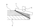
図3は、研磨パッド10をダイヤモンドドレッサ5によりドレッシングする際の様子を横から見た場合の概略図である。図3に示すように、ダイヤモンドドレッサ5は、自在継ぎ手15を介してドレッサ回転軸16に連結されている。ドレッサ回転軸16は図示しない回転機構に連結されている。ドレッサ回転軸16はドレッサアーム17に回転自在に支持されており、このドレッサアーム17により、ドレッサ5は研磨パッド10に接触しながら、図1に示すように揺動するようになっている。自在継ぎ手15は、ドレッサ5の傾動を許容しつつ、ドレッサ回転軸16の回転をドレッサ5に伝達するように構成されている。ドレッサ5、自在継ぎ手15、ドレッサ回転軸16、ドレッサアーム17、および図示しない回転機構などにより、ドレッシングユニット12が構成されている。このドレッシングユニット12には、ドレッサ5の摺動距離をシミュレーションにより求める演算装置130が電気的に接続されている。この演算装置130としては、専用または汎用のコンピュータを用いることができる。
FIG. 3 is a schematic view when the state of dressing the
研磨テーブル8は、研磨定盤9と、該研磨定盤9の上面に取り付けられた研磨パッド10とを備えている。研磨定盤9は図示しない回転機構により回転されるようになっており、研磨パッド10は研磨定盤9と一体に回転する。研磨対象物である半導体ウェーハは、後述するトップリングにより研磨パッド10の上面(すなわち研磨面)に押し付けられる。この状態で、研磨パッド10と半導体ウェーハとを相対運動させることにより、半導体ウェーハの表面が研磨される。なお、本実施形態においては、研磨部材を代表して研磨パッドが使用されているが、研磨部材は研磨パッドに限られず、研磨布などの他の例にも同様に本発明を適用することができる。
The polishing table 8 includes a polishing
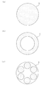
ドレッサ5の下面にはダイヤモンド粒子が固定されている。このダイヤモンド粒子が固定されている部分が、研磨パッド10の研磨面をドレッシングするドレッシング面を構成している。図4(a)乃至図4(c)は、それぞれドレッシング面の例を示す図である。図4(a)に示す例では、ドレッサ5の下面全体にダイヤモンド粒子が固定されており、円形のドレッシング面が形成されている。図4(b)に示す例では、ドレッサ5の下面の周縁部にダイヤモンド粒子が固定されており、リング状のドレッシング面が形成されている。図4(c)に示す例では、ドレッサ5の中心周りに略等間隔に配列された複数の小径ペレットの表面にダイヤモンド粒子が固定されており、複数の円形のドレッシング面が形成されている。
Diamond particles are fixed to the lower surface of the
研磨パッド10をドレッシングするときは、図3に示すように、研磨パッド10を図示しない回転機構によって例えば矢印Iの方向に所定の回転速度で回転させ、ドレッサ5を図示しない回転機構によって例えば矢印Hの方向に所定の回転速度で回転させる。そして、この状態で、ドレッサ5のドレッシング面(ダイヤモンド粒子が配置された面)を研磨パッド10に所定のドレッシング荷重で押圧してドレッシングを行う。また、ドレッサアーム17によってドレッサ5が研磨パッド10上を揺動することによって、研磨パッド10の研磨で使用される領域(研磨領域、即ち半導体ウェーハ等の研磨対象物を研磨する領域)をドレッシングすることができる。
When dressing the
なお、ドレッサ5が自在継ぎ手15およびドレッサ回転軸16を介して回転機構に連結されているので、研磨パッド10の表面とドレッサ回転軸16が少し傾いていても、ドレッサ5のドレッシング面は研磨パッド10に適切に当接する。
Since the
次に、ドレッサ5の揺動のさせ方について図1を参照して説明する。ドレッサアーム17は、ドレッサ揺動軸Oを中心にして揺動する。そして、ドレッサアーム17の揺動により、ドレッサ5の回転中心は、円弧Lで示す範囲で揺動する。
Next, how to swing the
ここで、例えばドレッサ5の下面全体にダイヤモンド粒子を配置したタイプのドレッサの場合(すなわち図4(a)の例の場合)、ドレッサ5の揺動速度が円弧Lの全領域にわたって一定であると、研磨パッド10上の各点におけるドレッサ5の摺動距離の分布は図5のようになる。なお、図5に示す摺動距離分布は、研磨パッド(研磨部材)の径方向におけるドレッサの摺動距離の分布である。また、図5の“規格化摺動距離”とは摺動距離の値を摺動距離の平均値で除したものである。ところで、一般に、研磨パッドの被研磨物に当接する領域内において、ドレッサによる研磨パッド削れ量分布が略均一であると、研磨パッドの研磨面が平坦になり、その結果、半導体ウェーハの被研磨面内での研磨速度(即ち除去レート)のばらつきが小さくなる。研磨パッド削れ量分布と摺動距離分布との間には略比例関係があると考えられるので、図5のような摺動距離分布の場合、半導体ウェーハの被研磨面内での研磨レートのばらつきが大きくなって好ましくない。
Here, for example, in the case of a dresser of a type in which diamond particles are arranged on the entire lower surface of the dresser 5 (that is, in the example of FIG. 4A), the rocking speed of the
このような事態を回避するために、ドレッサ5の揺動速度を円弧Lの場所によって変えることが行われる。例えば、円弧Lを幾つかの揺動区間に分割し、表1に示すように、その揺動区間ごとにドレッサ5の揺動速度を決定する。

ここで、ドレッシング時の研磨パッド10の回転速度、ドレッサ5の回転速度、ドレッシング荷重、ドレッサ5の揺動区間、ドレッサ5の揺動速度などの組み合わせを、ドレッシング条件(ドレッシングレシピ)と呼ぶ。もちろん、ドレッシング時間、揺動範囲(円弧Lの長さ)や、揺動半径(ドレッサ揺動軸Oから円弧Lまでの距離)もドレッシング条件に含んでも良い。なお、上記“揺動区間”とは“揺動範囲(円弧Lの長さ)”を研磨パッド10の半径方向に複数に分割した区間を意味する。上述のように、ドレッシング条件を実験的に決定するには多くの時間と労力が必要であったが、研磨パッド10の研磨面上の各点におけるドレッサ5の摺動距離がドレッサ5による研磨パッド10の削れ量と密接な関係にあることを利用することで、ドレッサ5の摺動距離分布を求め、ドレッシング条件を決定することができる。
Here, a combination of the rotational speed of the
ここで、ドレッサの摺動距離について説明する。ドレッサの摺動距離とは、ドレッサのダイヤモンド粒子が配置される領域、すなわちドレッシング面が、研磨パッドの表面(研磨面)上のある点を摺動する距離である。例えば、研磨パッド10とドレッサ5のいずれもが回転せずに、ドレッサ5が一直線に移動する場合を考える。図4(a)のような下面全体にダイヤモンド粒子が配置されたドレッサが、研磨パッド10上のある点をドレッサの中心が通るように移動する場合、その点でのドレッサの摺動距離はドレッサ直径と等しくなる。また、図4(b)のようなリング状にダイヤモンド粒子が配置されたドレッサが、研磨パッド10上のある点をドレッサの中心が通るように移動する場合、その点でのドレッサの摺動距離はリング幅の2倍の長さと等しくなる。これは、研磨パッド10上のある点でのドレッサの摺動距離が、その点でのドレッサの移動速度と、ダイヤモンド粒子が配置される領域(すなわちドレッシング面)の通過時間(接触時間)との積となることを表している。
Here, the sliding distance of the dresser will be described. The sliding distance of the dresser is the distance that the region where the diamond particles of the dresser are arranged, that is, the dressing surface, slides at a certain point on the surface (polishing surface) of the polishing pad. For example, consider a case where the
研磨パッド10とドレッサ5が共に回転し、さらにドレッサ5が移動する場合について考えると、研磨パッド10上のある点での摺動距離は、その点でのドレッサ5と研磨パッド10との相対速度をドレッシング開始から終了まで時間で積分した値となる。
Considering the case where the
上述のように、単にドレッサの摺動距離分布をシミュレーションするだけでは研磨パッドの削れ量分布を精度良く予測することはできない。したがって、単なる摺動距離分布のシミュレーションによって決定されたドレッシング条件で行うドレッシングでは、所望の研磨パッド削れ量分布でドレッシングをすることが困難である。 As described above, it is not possible to accurately predict the abrasion amount distribution of the polishing pad simply by simulating the sliding distance distribution of the dresser. Therefore, it is difficult to perform dressing with a desired polishing pad scraping amount distribution in dressing performed under dressing conditions determined simply by simulation of sliding distance distribution.
そこで、本発明は、従来よりも精度の良いシミュレーションを用いてドレッシング条件を決定することにより、所望の削れ量分布により近い削れ量分布でドレッシングできる方法を提供する。以下にそのシミュレーション方法を説明する。 Therefore, the present invention provides a method capable of dressing with a scraping amount distribution closer to a desired scraping amount distribution by determining dressing conditions using a more accurate simulation than in the past. The simulation method will be described below.
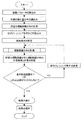
研磨パッドの削れ量が摺動距離に密接な関係があることは前述の通りである。しかし、削れ量分布と摺動距離分布との差が大きいため、ダイヤモンドドレッサのダイヤモンド粒子の研磨パッドへの食い込みを考慮して摺動距離分布を補正する。一例として、ある時刻から微小時間経過するまでの摺動距離の増分を、その時刻における研磨パッド上の各点の相対速度と微小時間の積として算出し、ドレッシング開始から終了までの摺動距離の増分を積算して摺動距離を求める摺動距離分布のシミュレーション方法を、図6のフローチャートを用いて説明する。 As described above, the amount of abrasion of the polishing pad is closely related to the sliding distance. However, since the difference between the scraping amount distribution and the sliding distance distribution is large, the sliding distance distribution is corrected in consideration of the biting of diamond particles of the diamond dresser into the polishing pad. As an example, the increment of the sliding distance from a certain time until a minute time elapses is calculated as the product of the relative speed of each point on the polishing pad and the minute time at that time, and the sliding distance from the start to the end of dressing is calculated. A sliding distance distribution simulation method for calculating the sliding distance by integrating the increments will be described with reference to the flowchart of FIG.
本実施例においては、演算装置130(図3参照)が設けられる。演算装置130(図3参照)は、まず、装置パラメータやドレッシング条件など、摺動距離分布のシミュレーションに必要なデータを読み込む。これらのデータは、プログラムに直接記述されても良いし、キーボードなどの入力装置から入力されても良い。また、研磨装置の制御コンピュータなどから読み込む様にしても良い。なお、図3においては、演算装置130はドレッシングユニット12に電気的に接続されているが、本発明はこの例に限定されない。例えば、演算装置130はドレッシングユニット12とは電気信号が直接やりとりされずに独立に設置されてもよい。この場合は、ドレッシング条件を探索するシミュレーション処理を演算装置(計算機)で実施し、そこで生成したドレッシング条件を、研磨装置の動作を制御する制御部(図示せず)に入力してドレッシングを行ってもよい。
In this embodiment, an arithmetic device 130 (see FIG. 3) is provided. The arithmetic device 130 (see FIG. 3) first reads data necessary for the simulation of the sliding distance distribution, such as device parameters and dressing conditions. These data may be directly described in the program, or may be input from an input device such as a keyboard. Further, it may be read from a control computer of the polishing apparatus. In FIG. 3, the
装置パラメータには、ドレッサ5のダイヤモンド粒子が配置される範囲に関するデータ、ドレッサ揺動軸の位置データ、ドレッサ5の揺動半径、研磨パッド10の直径、ドレッサ5の揺動の加速度などが含まれる。
The apparatus parameters include data relating to the range in which the diamond particles of the
ドレッサ5のダイヤモンド粒子が配置される範囲に関するデータとは、ドレッシング面の形状および大きさを含むデータである。例えば図4(a)のようなドレッサの下面全体にダイヤモンド粒子が配置されるドレッサであればドレッサ外径、図4(b)のようなリング状にダイヤモンド粒子が配置されるドレッサであればリングの外径と内径、図4(c)のような複数の小径ペレット上にダイヤモンド粒子が配置されるドレッサであれば各ペレットの中心位置およびダイヤモンド粒子の配置部分の直径などである。
The data regarding the range in which the diamond particles of the
ドレッシング条件には、研磨パッド10の回転速度、ドレッサ5の揺動開始位置、ドレッサ5の揺動範囲、揺動区間数、各揺動区間の区間幅、各揺動区間でのドレッサ5の揺動速度、ドレッサ5の回転速度、ドレッシング荷重、ドレッシング時間などが含まれる。
The dressing conditions include the rotational speed of the
なお、演算装置130は、装置パラメータやドレッシング条件と共に、ドレッシングの繰り返し数(設定繰り返し数)を読み込む。これは、ある一定の時間として定められた1回のドレッシング時間分のドレッシングについての摺動距離分布をシミュレーションしただけでは、研磨パッドの削れ量分布とドレッサの摺動距離分布との差が大きくなる可能性があるためである。例えば、1回のドレッシングにおけるドレッサの往復回数が少ない場合に、研磨パッドの削れ量分布とドレッサの摺動距離分布との差が大きくなることがある。
Note that the
次に、研磨パッド10の表面(研磨面)上の摺動距離算出点の座標を設定する。例えば、研磨パッド10の回転中心を原点とする円筒座標を研磨パッド10の研磨面上に定義し、研磨面を半径方向と円周方向に複数分割する格子の交点を摺動距離算出点とする。図7にその一例を示す。図7においては、同心円と、径方向に延びる線との交点が摺動距離算出点である。計算速度向上のためには、分割数を減らせばよい。また、必ずしも円周方向に分割する必要は無い。もちろん、円筒座標でなく、直交座標を定義してもなんら問題はない。
Next, the coordinates of the sliding distance calculation point on the surface (polishing surface) of the
次に、時間、各摺動距離算出点の摺動距離などの各種変数の初期値を設定する。これらの変数は、摺動距離の計算にともなって変動する。 Next, initial values of various variables such as time and the sliding distance of each sliding distance calculation point are set. These variables vary as the sliding distance is calculated.
次に、摺動距離算出点の間隔や研磨パッドの回転速度、ドレッサの回転速度、ドレッサの揺動速度などを用いて、時間刻み幅(微小時間)ΔTを決定する。 Next, the time increment (minute time) ΔT is determined using the distance between the sliding distance calculation points, the rotation speed of the polishing pad, the rotation speed of the dresser, the rocking speed of the dresser, and the like.
次に、演算装置130は、ある時刻における摺動距離算出点の座標とドレッサのドレッシング面の位置情報を元に、摺動距離算出点とドレッサとの接触判定を行う。
Next, the
次に、演算装置130は、摺動距離算出点におけるドレッサと研磨パッドとの相対速度Vrelを計算する。具体的には、ある時刻の各摺動距離算出点における、ドレッサの速度ベクトルと研磨パッドの速度ベクトルの差の大きさを求めることで相対速度Vrelを計算する。ここで、ドレッサの速度ベクトルは、ドレッサの回転による速度ベクトルとドレッサの揺動による速度ベクトルとの和となる。また、研磨パッドの速度ベクトルは、研磨パッドの回転による速度ベクトルとなる。
Next, the
次に、演算装置130は、ドレッサ接触面積比Sを計算する。ドレッサ接触面積比とは、ドレッシング面全体の面積(即ち一定の値)を、研磨パッドに接触しているドレッシング面の部分の面積(即ち可変の値)で割ったものである。ドレッシング荷重一定でドレッシングする場合、ドレッサの一部が研磨パッドの外縁からはみ出すと、はみ出した分だけドレッサと研磨パッドとの接触面圧(ドレッシング圧力)が大きくなる。研磨パッドの削れ量は接触面圧に略比例すると考えられるので、接触面圧が大きくなると研磨パッドの削れ量が大きくなる。したがって、摺動距離の計算においては、接触面圧の増分に比例して摺動距離を補正する必要がある。ドレッサ接触面積比Sは、この補正に使用される。もちろん、ドレッシング荷重が一定ではなく、ドレッシング圧力一定でドレッシングする場合は、摺動距離を補正する必要が無いので、ドレッサ接触面積比を算出する必要が無い。即ち、本発明においては、研磨部材削れ量は摺動距離自体に略比例するとの考え方を基本にしながら、研磨部材削れ量に影響を与える接触面圧の変化に応じて、摺動距離を補正することで、換言すれば接触面圧の変化を摺動距離に置き換えることで、研磨部材の削れ量と摺動距離との比例関係の正確さ(双方の比例関係の一致性)の向上を実現している。
Next, the
次に、演算装置130は、ある時刻から微小時間経過するまでの摺動距離の増分ΔD0を計算する。ΔD0は、相対速度Vrel、時間刻み幅ΔTの積となる。
ΔD0=Vrel×ΔT ・・・(1)
ここで、摺動距離算出点とドレッサとの接触判定でドレッサと接触しないと判定された摺動距離算出点においては、摺動距離の増分は0となる。
Next, the
ΔD 0 = Vrel × ΔT (1)
Here, the increment of the sliding distance is zero at the sliding distance calculation point determined not to contact the dresser in the contact determination between the sliding distance calculation point and the dresser.
次に、演算装置130は、摺動距離の増分ΔD0をドレッサ接触面積比Sで補正する。即ち、
ΔD1=ΔD0×S ・・・(2)
もちろん、ドレッシング圧力が一定でドレッシングする場合は、摺動距離を補正する必要が無いので、ΔD1=ΔD0である。
Next, the
ΔD 1 = ΔD 0 × S (2)
Of course, when dressing is performed at a constant dressing pressure, there is no need to correct the sliding distance, so ΔD 1 = ΔD 0 .
次に、補正された摺動距離の増分ΔD1を、ダイヤモンド粒子の研磨パッドへの食い込み量に応じて更に補正する。摺動距離にばらつきがあると、摺動距離が小さいところでは削れ量が小さいので研磨パッドが相対的に厚くなり、摺動距離が大きいところでは削れ量が大きいので研磨パッドが相対的に薄くなって、研磨パッドの研磨面にうねりが生じる。図8に示すように、研磨パッド10の研磨面にうねりがある場合、相対的に研磨パッド10の厚い部分ではダイヤモンド粒子5aの食い込みが大きく、相対的に研磨パッド10の薄い部分ではダイヤモンド粒子5aの食い込みが小さくなる。したがって、相対的に研磨パッド10の厚い部分では削れ量が大きく、相対的に研磨パッド10の薄い部分では削れ量が小さくなる。そこで、摺動距離が小さい部分では摺動距離が大きく、摺動距離が大きい部分では摺動距離が小さくなるように、摺動距離を補正する。
Next, the corrected increment ΔD 1 of the sliding distance is further corrected according to the amount of the diamond particles biting into the polishing pad. If the sliding distance varies, the polishing pad becomes relatively thick when the sliding distance is small, and the polishing pad becomes relatively thick.If the sliding distance is large, the polishing pad becomes relatively thin because the scraping amount is large. As a result, waviness occurs on the polishing surface of the polishing pad. As shown in FIG. 8, when the polishing surface of the
上記説明を簡単化して換言すれば、摺動距離が大きい所では研磨パッドが薄くなるのでダイヤモンド粒子の食い込みが小さくなり、研磨パッドの削れ量が小さい。したがって、摺動距離が大きい所では摺動距離が小さくなるように、摺動距離を補正する。反対に、摺動距離が小さい所では研磨部材が厚くなるのでダイヤモンド粒子の食い込みが大きくなり、研磨パッドの削れ量が大きい。したがって、摺動距離が小さい所では摺動距離が大きくなるように、摺動距離を補正する。 In other words, the above description is simplified. In other words, the polishing pad becomes thin at a place where the sliding distance is large, so that the bite of diamond particles is reduced and the amount of abrasion of the polishing pad is small. Therefore, the sliding distance is corrected so that the sliding distance becomes small at a place where the sliding distance is large. On the contrary, when the sliding distance is small, the polishing member becomes thick, so that the diamond particles bite in and the amount of abrasion of the polishing pad is large. Therefore, the sliding distance is corrected so that the sliding distance becomes large where the sliding distance is small.
ダイヤモンド粒子の食い込みを考慮した摺動距離増分ΔD1の補正方法の一例を、図9を用いて説明する。図9は、理解しやすいように、ある時刻においてドレッシング面が接触する領域付近の摺動距離分布を2次元で表した図である。図9において、細破線ではさまれた領域がドレッシング面が接触する領域、太実線がドレッサの摺動距離(D)、太破線がドレッシング面が接触する領域での摺動距離の平均値(DMEAN)であり、ドレッシング面が接触する領域における摺動距離の最大値と最小値をそれぞれDMAXとDMINとしている。ダイヤモンド粒子が研磨パッドに食い込む深さの大小は、ドレッサの摺動距離(D)の大小と逆の傾向を示す。前者が大のときは後者が小となり、前者が小の時には後者が大となる。従ってダイヤモンド粒子が研磨パッドに食い込む深さは、ドレッサの摺動距離(D)を用いて表現することが出来る。 An example of a method for correcting the sliding distance increment ΔD 1 in consideration of the biting of diamond particles will be described with reference to FIG. FIG. 9 is a two-dimensional representation of the sliding distance distribution near the area where the dressing surface contacts at a certain time for easy understanding. In FIG. 9, the area between the thin broken lines is the area where the dressing surface is in contact, the thick solid line is the dresser sliding distance (D), and the thick broken line is the average sliding distance in the area where the dressing surface is in contact (D MMAX ), and the maximum value and the minimum value of the sliding distance in the region where the dressing surface contacts are D MAX and D MIN , respectively. The depth at which the diamond particles bite into the polishing pad has a tendency opposite to that of the dresser sliding distance (D). When the former is large, the latter is small, and when the former is small, the latter is large. Therefore, the depth at which the diamond particles bite into the polishing pad can be expressed using the sliding distance (D) of the dresser.
ダイヤモンド粒子の食い込みを考慮して摺動距離増分ΔD1を補正するための補正係数K1を、例えば次式のように定義する。
ΔD2=ΔD1×K1 ・・・(4)
このように、本発明では、ダイヤモンド粒子の食い込み深さに応じて摺動距離を補正することにより、換言すればダイヤモンド粒子の食い込み深さを摺動距離に置き換えて、研磨部材の削れ量と摺動距離との比例関係の正確さ(双方の比例関係の一致性)の向上を実現している。
なお、補正された摺動距離の増分ΔD2が負の値をとらないように、補正係数K1の最小値は0とする。
A correction coefficient K 1 for correcting the sliding distance increment ΔD 1 in consideration of the bite of the diamond particles is defined as follows, for example.
ΔD 2 = ΔD 1 × K 1 (4)
As described above, in the present invention, by correcting the sliding distance according to the penetration depth of the diamond particles, in other words, replacing the penetration depth of the diamond particles with the sliding distance, The accuracy of the proportional relationship with the moving distance (coincidence of both proportional relationships) is improved.
Note that as the incremental [Delta] D 2 of the corrected sliding distance does not take a negative value, the minimum value of the correction coefficient K 1 is set to 0.
次に、補正された摺動距離の増分ΔD2を、ドレッサ5が研磨パッド10からはみ出したときのドレッサ5の傾きに応じて更に補正する。先述の様に、ドレッサ5は、ドレッシング面が研磨パッド10の研磨面から傾いた状態も許容できるように、自在継ぎ手15を介してドレッサ回転軸16に接続されている。したがって、ドレッサ5が研磨パッド10からはみ出すと、図10に示すように、研磨パッド10からの反力によるモーメントが自在継ぎ手15を中心に釣り合うようにドレッサ5が傾く(図10では理解しやすい様にドレッサ5の傾きを強調している)。ドレッサ5が研磨パッド10からはみ出していないときは、研磨パッド10とドレッサ5との接触圧力(ドレッシング圧力)分布は略均一である。しかし、ドレッサ5が研磨パッド10からはみ出すと、ドレッシング圧力分布が均一とはならず、概ね研磨パッド10の外縁に近づくにつれてドレッシング圧力は大きくなる。
Next, the corrected increment ΔD 2 of the sliding distance is further corrected according to the inclination of the
図11(a)は、直径740mmの研磨パッドを直径100mmのドレッサで研磨する際に、ドレッサの外周端が最大で研磨パッドから25mmはみ出した場合の様子を示す平面図であり、図11(b)は、研磨パッドの中心とドレッサの中心を通る直線上のドレッシング圧力分布を示した図である。図11(a)に示す例では、ドレッサの下面全体にダイヤモンド粒子が固着されたドレッサ(図4(a)参照)が使用されている。図11(b)は、ドレッシング荷重と研磨パッドからの反力との力の釣り合いと、研磨パッドからの反力の自在継ぎ手まわりのモーメントの釣り合いから導いたドレッシング圧力分布を示している。ここで、ドレッシング荷重とは、ドレッサ回転軸を経由してドレッサに加えられる力であって、研磨パッドにドレッサを押し付ける荷重である。図11(b)において、縦軸はドレッサが研磨パッドからはみ出していない場合のドレッシング圧力を1として規格化した規格化ドレッシング圧力である。すなわち、規格化ドレッシング圧力とは、ドレッサ中心から距離xmmだけ離れた位置における圧力を、ドレッシング面全体が研磨パッドに接した状態において研磨パッドに与える圧力で除した値である。横軸は、ドレッサ中心を0とした位置を表し、研磨パッド中心側の値は負となる。 FIG. 11A is a plan view showing a state where the outer peripheral end of the dresser protrudes 25 mm from the polishing pad at the maximum when the polishing pad having a diameter of 740 mm is polished with the dresser having a diameter of 100 mm, and FIG. ) Is a diagram showing a dressing pressure distribution on a straight line passing through the center of the polishing pad and the center of the dresser. In the example shown in FIG. 11A, a dresser (see FIG. 4A) in which diamond particles are fixed to the entire lower surface of the dresser is used. FIG. 11B shows the dressing pressure distribution derived from the balance of the force between the dressing load and the reaction force from the polishing pad and the balance of the moment around the universal joint of the reaction force from the polishing pad. Here, the dressing load is a force applied to the dresser via the dresser rotation shaft, and is a load that presses the dresser against the polishing pad. In FIG. 11 (b), the vertical axis represents the normalized dressing pressure normalized by setting the dressing pressure to 1 when the dresser does not protrude from the polishing pad. That is, the normalized dressing pressure is a value obtained by dividing the pressure at a position separated from the dresser center by a distance x mm by the pressure applied to the polishing pad when the entire dressing surface is in contact with the polishing pad. The horizontal axis represents the position where the dresser center is 0, and the value on the polishing pad center side is negative.
図11(a)および図11(b)から分かるように、ドレッサ5が研磨パッド10からはみ出した状態のドレッシング圧力は、ドレッサ中心からの位置(図11(a)に示す傾きの軸からの距離で、研磨パッド中心側が負の値:x)を用いて概ね1次関数で表すことができる。また、図12(a)に示すように、この1次関数の傾き(規格化傾き:fΔ)は、研磨パッド中心とドレッサ中心との距離(ドレッサ中心位置:C0)に対して一意に決まる。なお、規格化傾きとは、上記のように図11(b)の1次関数の直線上に例えば2点を仮想し、当該2点間の規格化ドレッシング圧力の差を当該2点間のドレッサ中心からの位置の差で除して求めたものである。また、ドレッサ中心でのドレッシング圧力の値は、研磨パッド中心とドレッサ中心との距離(ドレッサ中心位置:C0)に対して一意に決まる。その一例を図12(b)に示す。なお、図12(b)では、ドレッサ中心での規格化ドレッシング圧力の値そのものを示すのではなく、ドレッサ中心での規格化ドレッシング圧力を、ドレッシング圧力がその平均値となる位置での規格化ドレッシング圧力(図11(b)の例では規格化ドレッシング圧力はドレッサの中心からの距離が−12.5mmの位置で平均値になっている)で割って、規格化y切片(fy0)として表示している。したがって、あるドレッサ中心位置C0におけるドレッシング面上のある点の規格化ドレッシング圧力は、そのドレッサ中心位置C0でのドレッシング圧力の規格化傾きと規格化y切片、前記ある点のドレッサの傾きの軸からの距離(ドレッサの中心からの距離)によって計算することができる。したがって、ドレッサの傾きによる補正係数K2を次のように定義する。
K2=fΔ(C0)×x+fy0(C0) ・・・(5)
そして、摺動距離増分ΔD2を次のように補正する。
ΔD3=ΔD2×K2 ・・・(6)
このように本発明では、ドレッサの傾きに応じて摺動距離をさらに補正することにより、換言すればドレッサの傾きを摺動距離に置き換えることにより、研磨パッドの削れ量と摺動距離との比例関係の正確さ(双方の比例関係の一致性)の向上を実現している。
As can be seen from FIGS. 11A and 11B, the dressing pressure in a state where the
K 2 = f Δ (C 0 ) × x + f y0 (C 0) ··· (5)
Then, to correct the sliding distance increment [Delta] D 2 as follows.
ΔD 3 = ΔD 2 × K 2 (6)
As described above, in the present invention, by further correcting the sliding distance in accordance with the dresser inclination, in other words, by replacing the dresser inclination with the sliding distance, the amount of abrasion of the polishing pad and the sliding distance are proportional. Improves the accuracy of the relationship (consistency of the proportional relationship between the two).
摺動距離の増分ΔD3は、微小時間での摺動距離の増分ΔD0に対して、上述した式(2)、式(4)、および式(6)で表される補正を行った結果である。この摺動距離の増分ΔD3を、その時刻までの摺動距離に加えて、新たな摺動距離とする。その際、上述の様に研磨パッド削れ量がドレッシング荷重やドレッシング圧力に略比例すると考えられるので、設定したドレッシング荷重やドレッシング圧力に応じて、摺動距離の増分ΔD3をさらに補正しても良い。 The sliding distance increment ΔD 3 is a result of performing the correction represented by the above-described formulas (2), (4), and (6) with respect to the sliding distance increment ΔD 0 in a minute time. It is. The increment [Delta] D 3 of the sliding distance, in addition to the sliding distance up to that time, as a new sliding distance. At this time, as described above, the polishing pad scraping amount is considered to be substantially proportional to the dressing load and dressing pressure, and therefore the sliding distance increment ΔD 3 may be further corrected according to the set dressing load and dressing pressure. .
次に、演算装置130は、次の時間刻み幅(微小時間)における摺動距離の増分を計算するための準備を行う。すなわち、演算装置130は、研磨部材を仮想的に回転させて摺動距離算出点を移動させ、ドレッサを仮想的に揺動させてドレッサを移動させる。さらに、演算装置130は、時間の更新(時間に時間刻み幅を加える)を行う。ドレッサの移動においては、ドレッサの揺動の折り返し点や、揺動区間(表1参照)の間の点でのドレッサの加速度を考慮して、次の時間刻み幅におけるドレッサの位置を算出することが好ましい。つまり、研磨パッド10上の各点におけるドレッサ5の摺動距離を精度良くシミュレーションするためには、相対速度と時間刻み幅から算出した摺動距離の増分に対し、式(2)、式(4)及び式(6)で表わされる補正を行なえば十分というわけではない。研磨パッド10の回転中心側や外周端側においてドレッサ5は揺動の折り返しをするから、揺動速度が加速や減速(即ち正または負の加速)をし、単位時間当りのドレッサ5の揺動距離は変化する。またドレッサ5が揺動区間(表1参照)を跨いで移動するときには、揺動区間の境目及びその近傍領域では同様に揺動速度の加速または減速を伴うから、単位時間当りのドレッサ5の揺動距離は変化する。従って研磨パッド10上の各点における摺動距離そのものを精度良く算出するためにはドレッサ5の移動の加速度を考慮するのが好ましい。これによって一層精度の高い摺動距離を算出できる。
Next, the
時間がドレッシング時間に到達した場合、演算装置130は、時間を初期化し、設定繰り返し数になるまでドレッシング時間分の摺動距離計算を繰り返す。設定繰り返し数だけドレッシング時間分の摺動距離の計算が終了したら、演算装置130は、結果を表示し、保存するなどの終了処理を行う。ここで、摺動距離が研磨部材削れ量に略比例することから、計算された摺動距離に変換係数(比例定数)を掛けて削れ量の計算結果としても良い。
When the time reaches the dressing time, the
なお、図6を用いた上述の説明では、単なる摺動距離増分ΔD0の計算、ドレッサ接触面積比による摺動距離増分の補正、ダイヤモンド粒子の食い込みによる摺動距離増分の補正、ドレッサ傾きによる摺動距離増分の補正の順に行ったが、最終的な摺動距離の増分ΔD3は、式(2)、式(4)、式(6)から、
ΔD3=ΔD0×S×K1×K2 ・・・(7)
となり、補正の順番に依存しない。
In the above description using FIG. 6, the calculation of the mere sliding distance increment ΔD 0 , the correction of the sliding distance increment based on the dresser contact area ratio, the correction of the sliding distance increment due to the biting of diamond particles, and the sliding due to the dresser inclination are performed. was performed in the order of correction of dynamic range increment, increment [Delta] D 3 of the final sliding distance, from equation (2), equation (4), equation (6),
ΔD 3 = ΔD 0 × S × K 1 × K 2 (7)
And does not depend on the order of correction.
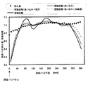
図13は、上述の方法で摺動距離分布をシミュレーションした結果と、研磨パッド削れ量の測定結果とを比較した図である。それぞれの値はそれぞれの平均値で除して規格化してある。図13において、菱形マークが研磨パッド削れ量の実測値、太実線が単に摺動距離を計算しただけの結果(図2と同じ)、細実線が摺動距離をダイヤモンド粒子の研磨パッドへの食い込みを考慮して補正した結果、細破線が摺動距離をダイヤモンド粒子の研磨パッドへの食い込みとドレッサの研磨パッドからのはみ出しによる傾きを考慮して補正した結果である。また、太破線は、ドレッサ移動の加速度を考慮して計算した摺動距離をダイヤモンド粒子の研磨パッドへの食い込みを考慮して補正した結果である。なお、いずれの計算結果においても、補正係数K1の式(3)のαを定数としている。 FIG. 13 is a diagram comparing the result of simulating the sliding distance distribution by the above-described method and the measurement result of the polishing pad scraping amount. Each value is normalized by dividing by its average value. In FIG. 13, the diamond mark indicates the measured value of the polishing pad scraping amount, the thick solid line merely calculates the sliding distance (same as in FIG. 2), and the thin solid line indicates the sliding distance biting into the polishing pad of diamond particles. As a result of correction in consideration of the above, the thin broken line is the result of correcting the sliding distance in consideration of the inclination caused by the bite of the diamond particles into the polishing pad and the protrusion of the dresser from the polishing pad. The thick broken line is the result of correcting the sliding distance calculated in consideration of the acceleration of the dresser movement in consideration of the bite of the diamond particles into the polishing pad. In any calculation result, α in equation (3) of the correction coefficient K 1 is a constant.
図13から分かるように、単に摺動距離を計算しただけの結果に比べて、研磨パッドへのダイヤモンド粒子の食い込みを考慮して摺動距離を補正した結果は、摺動距離のうねりが小さくなり、研磨パッド削れ量の測定結果に近い分布を示している。また、ダイヤモンド粒子の食い込みに加えて、ドレッサの傾きやドレッサ揺動の加速度を考慮した結果は、研磨パッド外周部において摺動距離が大きくなっており、実際の削れ量分布により近い分布となっている。 As can be seen from FIG. 13, the result of correcting the sliding distance in consideration of the bite of the diamond particles into the polishing pad is smaller than the result of simply calculating the sliding distance. The distribution close to the measurement result of the polishing pad scraping amount is shown. In addition to the bite of the diamond particles, the result of considering the dresser inclination and the acceleration of the dresser oscillation shows that the sliding distance is larger at the outer periphery of the polishing pad, which is closer to the actual wear amount distribution. Yes.
図14は、研磨パッドへのダイヤモンド粒子の食い込みと、ドレッサのはみ出しによるドレッサの傾きと、ドレッサ揺動の加速度とを全て考慮した場合の摺動距離分布のシミュレーション結果と、研磨パッド削れ量分布の測定結果を比較した図である。図14から、摺動距離分布と削れ量分布が良く一致していることが分かる。したがって、本シミュレーション方法によれば、従来の単に摺動距離分布だけをシミュレーションした場合に比べて、より精度良く研磨パッドの削れ量分布を予測することができる。 FIG. 14 shows a simulation result of a sliding distance distribution in consideration of all of the bite of diamond particles into the polishing pad, the inclination of the dresser due to the protrusion of the dresser, and the acceleration of the dresser swing, and the polishing pad scraping amount distribution. It is the figure which compared the measurement result. FIG. 14 shows that the sliding distance distribution and the shaving amount distribution are in good agreement. Therefore, according to the present simulation method, it is possible to predict the abrasion amount distribution of the polishing pad more accurately than in the case where only the conventional sliding distance distribution is simulated.
次に、上述のシミュレーション方法を用いたドレッシング条件の探索方法について、図15を参照して説明する。図15は、所望の研磨部材削れ量分布が得られる所望の摺動距離分布を、仮のドレッシング条件を種々変更して探索するフローチャートである。 Next, a method for searching for dressing conditions using the above-described simulation method will be described with reference to FIG. FIG. 15 is a flowchart for searching for a desired sliding distance distribution from which a desired abrasive member scraping amount distribution can be obtained by changing various temporary dressing conditions.
まず、演算装置130は、装置パラメータを読み込む。装置パラメータは、プログラムに直接記述されても良いし、キーボードなどの入力装置から入力されても良い。また、研磨装置の制御コンピュータなどから読み込む様にしても良い。装置パラメータには、ドレッサのダイヤモンドが配置される範囲に関するデータ、ドレッサ揺動軸の位置データ、ドレッサ揺動半径、研磨パッド直径、ドレッサ揺動の加速度などが含まれる。
First, the
次に、演算装置130は、所望の研磨部材の削れ量分布を読み込む。所望の削れ量分布は、プログラムに直接記述されても良いし、キーボードなどの入力装置から入力されても良い。また、所望の削れ量分布のデータ形式は、研磨部材半径(研磨部材の中心からの径方向距離)と削れ量との関係が一意に決まるデータ形式であれば良い。例えば、表2の様な複数の研磨部材半径と削れ量とが1対1に対応したデータであれば、その中間の値を直線や3次スプラインで補完することにより決定することができる。また、所望の削れ量分布が均一な削れ量分布である場合は、均一な削れ量分布であることをプログラムに直接記述したり入力装置から入力したりすれば良い。
次に、演算装置130は、所望の削れ量分布から所望の摺動距離分布を計算する。例えば、所望の削れ量分布をその平均値で規格化することによって、規格化された所望の摺動距離分布とする。この場合、所望の削れ量分布が均一な削れ量分布であれば、所望の摺動距離分布は研磨部材上の場所によらず1となる。なお、他の方法としては、摺動距離が削れ量に略比例すると考えられることから、所望の削れ量分布をその比例定数(変換係数)で割って、所望の摺動距離分布とする方法がある。
Next, the
次に、演算装置130は、ドレッシング条件の探索のスタートとなる仮のドレッシング条件を読み込む。仮のドレッシング条件は、プログラムに直接記述されても良いし、キーボードなどの入力装置から入力されても良い。また、研磨装置の制御コンピュータなどから読み込む様にしても良い。仮のドレッシング条件には、研磨部材回転速度、ドレッサの揺動開始位置、ドレッサの揺動範囲、揺動区間数、各揺動区間の区間幅、各揺動区間の揺動速度、ドレッサ回転速度、ドレッシング荷重、ドレッシング時間などが含まれる。
Next, the
次に、ドレッシング条件を探索する際の制約条件を演算装置130に設定する。制約条件は、プログラムに直接記述されても良いし、キーボードなどの入力装置から入力されても良い。また、研磨装置の制御コンピュータなどから読み込む様にしても良い。制約条件には、研磨部材回転速度、ドレッサの揺動開始位置、ドレッサの揺動範囲、揺動区間数、各揺動区間の区間幅、各揺動区間の揺動速度、ドレッサ回転速度、ドレッシング荷重、ドレッシング時間などの下限値、上限値が含まれる。ここで、パラメータによっては下限値と上限値が同じであっても良い。例えば、研磨部材回転速度の下限値と上限値を等しく設定した場合、研磨部材回転速度は下限値(および上限値)に固定される。また、制約条件と共に、ドレッシングの繰り返し数(設定繰り返し数)を演算装置130に設定する。
Next, a restriction condition for searching for the dressing condition is set in the
次に、演算装置130は、仮のドレッシング条件における摺動距離分布を計算する。摺動距離分布の計算は、図6のフローチャートを用いて説明した上述の方法で実施する。その際、入力された装置パラメータや仮のドレッシング条件は、摺動距離分布の計算に使用される。
Next, the
次に、演算装置130は、所望の摺動距離分布と摺動距離分布の計算結果との差を計算する。具体的には、例えば、各摺動距離算出点における所望の摺動距離分布と摺動距離の計算結果との差の2乗和や差の絶対値の和を算出する。その際、摺動距離算出点の範囲を限定しても良い。
Next, the
次に、演算装置130は、所望の摺動距離分布と摺動距離分布の計算結果との差が許容範囲内か、あるいは、仮のドレッシング条件を変えてもこれ以上その差が有意に小さくならないかを判断する。差が許容範囲内でなく、かつ仮のドレッシング条件を変えると差が有意に小さくなると判断される場合は、演算装置130は、仮のドレッシング条件を変更して、再度摺動距離分布の計算から繰り返す。差が許容範囲内であるか、仮のドレッシング条件を変えても差が有意に小さくならないと判断される場合は、演算装置130は、その仮のドレッシング条件を所望のドレッシング条件として、結果の表示や保存といった終了処理を行う。
Next, the
なお、ドレッシング条件の探索には、実験計画法や市販の最適化ツールを使用することができる。例えば、Minitab Inc.製のMinitabや、MathWorks Inc.が開発しているMATLAB Optimization Toolboxを使用することができる。 For searching for dressing conditions, an experimental design method or a commercially available optimization tool can be used. For example, Minitab Inc. Manufactured by Minitab and MathWorks Inc. Can use MATLAB Lab Optimization Tool.
次に、上述のドレッシング条件探索方法を用いてドレッシング条件を探索した結果について説明する。図14のドレッシング条件からドレッサ回転速度のみを変更し、他のドレッシング条件を変更しないという制約条件の下で、均一な研磨パッド削れ量分布となるようにドレッシング条件を探索した。図16は、ドレッシング条件探索結果における摺動距離分布のシミュレーション結果と、ドレッシング条件探索結果を用いて研磨パッドをドレッシングした際の研磨パッド削れ量分布の測定結果を示す。図14と比較すると、特に研磨パッドの中心からの径方向距離が小さい領域において、摺動距離および削れ量が均一となるようにドレッシング条件(ここではドレッサ回転速度)が最適化されていることが分かる。これにより、本手法の有効性が確認できる。なお、図14および図16の摺動距離と削れ量は、それぞれの平均値で規格化している。 Next, the results of searching for dressing conditions using the above-described dressing condition searching method will be described. Under the constraint that only the dresser rotation speed is changed from the dressing conditions of FIG. 14 and the other dressing conditions are not changed, the dressing conditions were searched for a uniform polishing pad scraping amount distribution. FIG. 16 shows the simulation result of the sliding distance distribution in the dressing condition search result and the measurement result of the polishing pad scraping amount distribution when dressing the polishing pad using the dressing condition search result. Compared to FIG. 14, the dressing conditions (here, the dresser rotation speed) are optimized so that the sliding distance and the scraping amount are uniform, particularly in a region where the radial distance from the center of the polishing pad is small. I understand. Thereby, the effectiveness of this method can be confirmed. Note that the sliding distance and the scraping amount in FIGS. 14 and 16 are normalized by their average values.
次に、上述のドレッシング条件探索方法を用いて、図14のドレッシング条件からドレッサ揺動速度のみを変更し、他のドレッシング条件を変更しないという制約条件の下で、均一な研磨パッド削れ量分布となるようにドレッシング条件を探索した。また、図14のドレッシング条件からドレッサ揺動速度とドレッサ揺動区間幅のみを変更し、他のドレッシング条件を変更しないという制約条件の下で、均一な研磨パッド削れ量分布となるようにドレッシング条件を探索した。図17は、それぞれのドレッシング条件探索結果における摺動距離分布のシミュレーション結果である。図において、細実線が図14のドレッシング条件における摺動距離分布、太一点差線がドレッサ揺動速度のみを変更して探索したドレッシング条件での摺動距離分布、太実線がドレッサ揺動速度とドレッサ揺動区間幅のみを変更して探索したドレッシング条件での摺動距離分布である。本手法により、図14のドレッシング条件に比べて、特に研磨パッドの中心からの径方向距離が約100mm以上の領域でより均一な摺動距離分布が得られることが分かる。なお、図17において、摺動距離はその平均値で規格化している。 Next, using the above-described dressing condition search method, only the dresser swing speed is changed from the dressing condition of FIG. 14 and the other polishing dressing distribution is uniformly distributed under the constraint that the other dressing conditions are not changed. The dressing conditions were searched as follows. Further, under the constraint that only the dresser swing speed and the dresser swing section width are changed from the dressing conditions of FIG. 14 and the other dressing conditions are not changed, the dressing conditions are set so as to obtain a uniform polishing pad scraping amount distribution. Explored. FIG. 17 is a simulation result of sliding distance distribution in each dressing condition search result. In the figure, the thin solid line is the sliding distance distribution under the dressing conditions in FIG. 14, the thick dotted line is the sliding distance distribution under the dressing conditions searched by changing only the dresser swing speed, and the thick solid line is the dresser swing speed. It is the sliding distance distribution under the dressing condition searched by changing only the dresser swinging section width. Compared with the dressing conditions of FIG. 14, it can be seen that a more uniform sliding distance distribution can be obtained by this method, particularly in a region where the radial distance from the center of the polishing pad is about 100 mm or more. In FIG. 17, the sliding distance is normalized by the average value.
図18は、本発明の実施形態に係る主として半導体ウェーハを研磨するための研磨装置を示す平面図である。図18に示す研磨装置は、多数の半導体ウェーハ(研磨対象物)をストックするウェーハカセット21を載置するロード・アンロードステージ22を4つ備えている。ロード・アンロードステージ22は、昇降可能な機構を有していても良い。ロード・アンロードステージ22上の各ウェーハカセット21に到達可能となるように、走行機構23の上に2つのハンドを有した搬送ロボット24が配置されている。
FIG. 18 is a plan view showing a polishing apparatus mainly for polishing a semiconductor wafer according to an embodiment of the present invention. The polishing apparatus shown in FIG. 18 includes four load / unload
搬送ロボット24における2つのハンドのうち、下側のハンドは、ウェーハカセット21より半導体ウェーハを受け取る時のみに使用される。また、上側のハンドは、ウェーハカセット21に半導体ウェーハを戻す時に使用される。これは、洗浄した後のクリーンな半導体ウェーハを上側にして、半導体ウェーハを汚さないためである。下側のハンドは、半導体ウェーハを真空吸着する吸着型ハンドであり、上側のハンドは、半導体ウェーハの周縁部を保持する落し込み型ハンドである。吸着型ハンドは、ウェーハカセット21内の半導体ウェーハのずれに関係なく半導体ウェーハを確実に搬送でき、落し込み型ハンドは、真空吸着のようにごみを集めてこないので、半導体ウェーハの裏面のクリーン度を保って半導体ウェーハを搬送できる。
Of the two hands in the
搬送ロボット24の走行機構23を対称軸に、ウェーハカセット21とは反対側に2台の洗浄機25,26が配置されている。各洗浄機25,26は、搬送ロボット24のハンドが到達可能な位置に配置されている。また、2台の洗浄機25,26の間で、ロボット24が到達可能な位置に、4つの半導体ウェーハの載置台27,28,29,30を備えたウェーハステーション70が配置されている。洗浄機25,26は、半導体ウェーハを高速回転させて乾燥させるスピンドライ機能を有しており、これによりモジュールを交換することなく半導体ウェーハの2段洗浄及び3段洗浄を行うことができる。
Two
洗浄機25,26と載置台27,28,29,30が配置されている領域Bと、ウェーハカセット21、搬送ロボット24が配置されている領域Aのクリーン度を分けるために隔壁84が配置されている。互いの領域A,Bの間で半導体ウェーハの搬送を可能とするために、隔壁84には開口部が設けられている。この開口部にはシャッター31が設けられている。洗浄機25と3つの載置台27,29,30に到達可能な位置に2つのハンドを有した搬送ロボット80が配置されており、洗浄機26と3つの載置台28,29,30に到達可能な位置に2つのハンドを有した搬送ロボット81が配置されている。
A partition wall 84 is arranged to separate the cleanliness between the area B where the
載置台27は、搬送ロボット24と搬送ロボット80との間で半導体ウェーハを受渡すために使用され、半導体ウェーハの有無検知用センサ91を具備している。載置台28は、搬送ロボット24と搬送ロボット81との間で半導体ウェーハを受渡すために使用され、半導体ウェーハの有無検知用センサ92を具備する。載置台29は、搬送ロボット81から搬送ロボット80へ半導体ウェーハを搬送するために使用され、半導体ウェーハの有無検知用センサ93と半導体ウェーハの乾燥防止、または洗浄用のリンスノズル95を具備している。
The mounting table 27 is used to deliver a semiconductor wafer between the
載置台30は、搬送ロボット80から搬送ロボット81へ半導体ウェーハを搬送するために使用され、半導体ウェーハの有無検知用センサ94と半導体ウェーハの乾燥防止、または洗浄用のリンスノズル96を具備している。載置台29,30は、共通の防水カバーの中に配置されていて、搬送用のカバー開口部にはシャッター97を設けている。載置台29は載置台30の上にあり、洗浄後の半導体ウェーハを載置台29に、洗浄前の半導体ウェーハを載置台30に置くことにより、リンス水の落下による半導体ウェーハと載置台29の汚染を防止している。なお、図18においては、センサ91,92,93,94、リンスノズル95,96及びシャッター97は模式的に示したものであって、位置および形状は正確に図示されていない。
The mounting table 30 is used to transfer a semiconductor wafer from the
搬送ロボット80,81の上側のハンドは、洗浄された半導体ウェーハを洗浄機25,26またはウェーハステーション70の載置台へ搬送するのに使用され、下側のハンドは、1度も洗浄されていない半導体ウェーハ、及び研磨される前の半導体ウェーハを搬送するのに使用される。下側のハンドで反転機への半導体ウェーハの出し入れを行うことにより、反転機上部の壁からのリンス水の滴により上側のハンドを汚染することがない。洗浄機25と隣接するように、搬送ロボット80のハンドが到達可能な位置に洗浄機82が配置されている。また、洗浄機26と隣接するように、搬送ロボット81のハンドが到達可能な位置に洗浄機83が配置されている。洗浄機25,26,82,83、ウェーハステーション70の載置台27,28,29,30及び搬送ロボット80,81は、全て領域Bの中に配置されていて、領域A内の気圧よりも低い気圧に調整されている。洗浄機82,83は、例えば半導体ウェーハの両面洗浄可能な洗浄機である。
The upper hand of the
この研磨装置は、各機器を囲むようにハウジング66を有しており、ハウジング66内は、隔壁84、隔壁85、隔壁86、隔壁87及び隔壁67により複数の部屋(領域A、領域Bを含む)に区画されている。隔壁87によって領域Bと区分されたポリッシング室が形成され、ポリッシング室は、更に隔壁67によって、第一の研磨部である領域Cと第二の研磨部である領域Dに区分されている。そして、2つの領域C,Dにはそれぞれ2つの研磨テーブルと、半導体ウェーハを保持しかつ半導体ウェーハを前記研磨テーブルに対して押し付けながら研磨するための1つのトップリングが配置されている。即ち、領域Cには研磨テーブル8,56、領域Dには研磨テーブル11,57がそれぞれ配置されており、また、領域Cにはトップリング52、領域Dにはトップリング53がそれぞれ配置されている。
This polishing apparatus has a
研磨テーブル8,11,56,57は、研磨部材として研磨パッド10を有しており(図3参照)、研磨パッド10の上面は研磨面を構成している。研磨の目的に応じてそれぞれ種類の異なる研磨パッドが使用されることもある。また、領域C内の研磨テーブル8に研磨砥液を供給するための砥液ノズル60と、研磨テーブル8のドレッシングを行うためのダイヤモンドドレッサ5とが配置されている。領域D内の研磨テーブル11に研磨砥液を供給するための砥液ノズル61と、研磨テーブル11のドレッシングを行うためのダイヤモンドドレッサ6とが配置されている。
The polishing tables 8, 11, 56, 57 have a
ダイヤモンドドレッサ5および6は半導体ウェーハよりも小さい径の小径ドレッサであり、ダイヤモンド砥粒が表面(研磨パッドに当接する面)に配置されたドレッシング面を有している。また、ダイヤモンドドレッサ5および6は、それぞれ揺動可能なドレッサアーム17および18の先端付近に設置され、ドレッサアーム17および18の揺動によって研磨テーブル8および11上を揺動可能なドレッシングユニットとして構成されている(図3の符号12参照)。
The
なお、研磨テーブル56,57の替わりに、湿式タイプの膜厚測定機を設置してもよい。その場合は、研磨直後に、膜厚測定機で半導体ウェーハ表面の膜の厚さを測定することができ、半導体ウェーハ表面の膜の削り増しや、測定値を利用して次の半導体ウェーハの研磨プロセスの制御を行うこともできる。 Instead of the polishing tables 56 and 57, a wet type film thickness measuring machine may be installed. In this case, immediately after polishing, the film thickness on the surface of the semiconductor wafer can be measured with a film thickness measuring device, and the film thickness on the surface of the semiconductor wafer is increased or the next semiconductor wafer is polished using the measured value. Process control can also be performed.
ポリッシング室と領域Bの間で半導体ウェーハの受け渡しを行うために、搬送ロボット80,81とトップリング52,53が到達可能な位置に、半導体ウェーハを表裏反転する反転機99,100,101,102を備えた回転式ウェーハステーション98が配置されている。反転機99,100,101,102は、回転式ウェーハステーション98の回転に伴って回転する。
In order to transfer the semiconductor wafer between the polishing chamber and the region B, the reversing
ポリッシング室と領域Bの間での半導体ウェーハの受け渡し方法を説明する。今、回転式ウェーハステーション98に備えられている反転機99,100,101,102は、図18のように、領域B側に反転機99,100が、領域C側に反転機101が、領域D側に反転機102がそれぞれ配置されているとする。研磨に供される半導体ウェーハは、ウェーハステーション70から搬送ロボット80により回転式ウェーハステーション98の領域B側に配置される反転機99に渡される。また、別の半導体ウェーハは、ウェーハステーション70から搬送ロボット81により回転式ウェーハステーション98の領域B側に配置される反転機100に渡される。
A method for delivering a semiconductor wafer between the polishing chamber and the region B will be described. As shown in FIG. 18, the reversing
なお、搬送ロボット80が半導体ウェーハを回転式ウェーハステーション98に搬送する時には、隔壁87に設けられたシャッター45が開き、領域Bとポリッシング室との間の半導体ウェーハの受け渡しが可能となる。また、搬送ロボット81が半導体ウェーハを回転式ウェーハステーション98に搬送する時には、隔壁87に設けられたシャッター46が開き、領域Bとポリッシング室との間の半導体ウェーハの受け渡しが可能となる。
When the
反転機99に半導体ウェーハを渡たし、反転機100に別の半導体ウェーハを渡した後、回転式ウェーハステーション98がその軸を中心に180度回転し、反転機99を領域D側に、反転機100を領域C側に移動させる。回転式ウェーハステーション98により領域C側へ移動した半導体ウェーハは、反転機100により被研磨面(表面)が下向きに反転させられてからトップリング52へ移送される。また、回転式ウェーハステーション98により領域D側へ移動した半導体ウェーハは、反転機99により被研磨面(表面)が下向きに反転させられてからトップリング53へ移送される。
After passing the semiconductor wafer to the reversing
トップリング52,53に移送された半導体ウェーハは、トップリング52,53の真空吸着機構により吸着され、半導体ウェーハは、研磨テーブル8,11まで吸着されたまま搬送される。そして、半導体ウェーハは、研磨テーブル8,11上に取り付けられた研磨パッド10で研磨される。
The semiconductor wafer transferred to the top rings 52 and 53 is adsorbed by the vacuum adsorption mechanism of the top rings 52 and 53, and the semiconductor wafer is conveyed while being adsorbed to the polishing tables 8 and 11. Then, the semiconductor wafer is polished by the
図19は、研磨中における、トップリング52と研磨テーブル8の一部を模式的に示す断面図である。トップリング53および研磨テーブル11も同様の構造である。図19に示す様に、研磨対象物である半導体ウェーハWの保持部であるトップリング52は、半導体ウェーハWを研磨部材(研磨パッド)10に所定の圧力で押し付けるためのエアバッグ54と、研磨対象物2を取り囲むように設置された支持部(リテーナリング)58と、リテーナリング58を所定の圧力で半導体ウェーハWの周囲の研磨パッド10に押し付けるためのエアバッグ55を備えている。
FIG. 19 is a cross-sectional view schematically showing a part of the
この実施の形態では、図19に示すように、リテーナリング58は、半導体ウェーハWの外周を囲む環状の形状を有しており、縦断面が長方形の単一の部材で構成されている。リテーナリング58と、トップリング52に保持された半導体ウェーハWの外周との間には若干の隙間が形成されている。リテーナリング58の下面は、半導体ウェーハWの表面(被研磨面)からの研磨パッド10のはみ出し部分を支持する支持面をなし、全体に亘って略平坦となっている。リテーナリング58の材質は、例えば、ジルコニアやアルミナ等のセラミック材料や、エポキシ(EP)樹脂やフェノール(PF)樹脂、ポリフェニレンサルファイド(PPS)樹脂等のエンジニアリングプラスチック材料で構成される。
In this embodiment, as shown in FIG. 19, the
リテーナリング58を研磨パッド10に押し付ける圧力は、例えば圧力調整機構108によりエアバッグ55の圧力を制御して調整することができる。また、エアバッグ55を備えることなく、トップリング52の回転駆動軸からの荷重をシリンダなどの圧力調整機構108で制御することで、支持面圧を調整するようにしても良い。エアバッグ54は、図19の様に一つの区画であっても良いし、同心円状に複数の区画に分かれていても良い。
The pressure for pressing the
図19に示すように、研磨テーブル8は、研磨定盤9と研磨パッド10を備えている。研磨パッド10は、一層の単層パッドであっても良いし、二層以上の多層パッドであっても良い。トップリング52は、図示しない駆動機構により、研磨パッド10の研磨面に対して垂直な方向(矢印Gで示す)に移動可能となっている。研磨の際に、トップリング52は、半導体ウェーハWを研磨パッド10に押付けながら、回転駆動機構(図示せず)により、その回転駆動軸を中心に例えば矢印Eの向きに回転する。また、研磨の際に、研磨テーブル8もその回転駆動軸を中心に例えば矢印Fの方向に回転する。このように、本実施形態では、トップリング52および研磨定盤9によって半導体ウェーハWと研磨パッド10が相対運動し、これによって半導体ウェーハWの表面が研磨される。
As shown in FIG. 19, the polishing table 8 includes a polishing
図18に戻って、図18では、更にトップリング52,53がそれぞれに到達可能な位置に、前述した第2の研磨テーブル56,57が配置されている。これにより、半導体ウェーハは、第1の研磨テーブル8,11で研磨が終了した後、第2の研磨テーブル56,57の仕上げ用研磨パッドで仕上げ研磨できるようになっている。第2の研磨テーブル56,57では、SUBA400やPolytex(共に研磨パッドの商品名であってロデール・ニッタ製)等の研磨パッドに純水、または砥粒を含まない薬液を供給しながら仕上げ研磨を行うか、またはスラリーを供給して研磨を行う。研磨の間に、次の研磨に供される半導体ウェーハが、領域B側に移動した反転機101,102に、搬送ロボット80,81により渡されていても良い。
Returning to FIG. 18, in FIG. 18, the second polishing tables 56 and 57 described above are arranged at positions where the top rings 52 and 53 can reach each other. As a result, the semiconductor wafer can be finished and polished by the finishing polishing pads of the second polishing tables 56 and 57 after the polishing by the first polishing tables 8 and 11 is completed. In the second polishing tables 56 and 57, final polishing is performed while supplying pure water or a chemical solution containing no abrasive grains to a polishing pad such as SUBA400 or Polytex (both are names of polishing pads and manufactured by Rodel Nitta). Polishing is performed by supplying a slurry. During the polishing, the semiconductor wafer to be used for the next polishing may be transferred by the
研磨が終了した半導体ウェーハは、トップリング52,53により、それぞれ反転機99,100に移送される。反転機99,100に移送された半導体ウェーハは、反転機99,100により、研磨後の表面(研磨面)が上向きになるように反転させられる。その後、回転式ウェーハステーション98が180度回転し、領域B側へ移動する。領域B側へ移動した半導体ウェーハは、反転機99から搬送ロボット80により洗浄機82またはウェーハステーション70に搬送される。また、領域B側へ移動した別の半導体ウェーハは、反転機100から搬送ロボット81により洗浄機83またはウェーハステーション70に搬送される。半導体ウェーハは、その後、適切な洗浄工程を経てウェーハカセット21へ収納される。
The polished semiconductor wafer is transferred to reversing
研磨テーブル8,11での研磨が終了した後に、研磨テーブル8,11の最上面を構成する研磨パッド10をダイヤモンドドレッサ5,6によりドレッシングする(図3参照)。ドレッシングの際に、砥液ノズル60,61は、純水などの洗浄液を研磨パッド10に供給する。このドレッシングにより、研磨パッドの研磨面の洗浄、目立て、形状修正などが行われる。
After the polishing with the polishing tables 8 and 11 is completed, the
このドレッシングの際に、研磨装置は、決められた研磨パッド回転速度、ドレッサ回転速度、ドレッシング荷重、ドレッサ揺動区間、ドレッサ揺動速度などの組み合わせ、即ち決められたドレッシング条件(ドレッシングレシピ)によりドレッシングを行う。上記ドレッシング条件は、本実施例では、演算部130により決められたものである。
During this dressing, the polishing apparatus performs dressing according to a combination of a determined polishing pad rotation speed, dresser rotation speed, dressing load, dresser swinging section, dresser swinging speed, etc., that is, a predetermined dressing condition (dressing recipe). I do. In the present embodiment, the dressing conditions are determined by the
図3に示すように、本研磨装置においては、研磨パッド10を図示しない回転機構によって例えば矢印Iの方向に所定の回転速度で回転させ、ダイヤモンドドレッサ5を図示しない回転機構によって例えば矢印Hの方向に所定の回転速度で回転させながら、ダイヤモンドドレッサ5のダイヤモンド粒子が配置された面、すなわちドレッシング面を研磨パッド10に所定のドレッシング荷重で当接させてドレッシングを行う。また、ドレッサアーム17によってドレッサ5が研磨パッド10上を揺動することによって、研磨パッド10の研磨で使用される領域(即ち研磨領域)をドレッシングすることができる。なお、図3の例では、ドレッシングユニット12は、ドレッサ5、自在継ぎ手15、ドレッサ回転軸16およびドレッサアーム17を備えて構成される。
As shown in FIG. 3, in the present polishing apparatus, the
研磨パッド10のドレッシングは、所望の研磨パッド削れ量分布となるように、ダイヤモンド粒子の研磨パッドへの食い込みを考慮した摺動距離分布シミュレーションを用いて決定したドレッシング条件(ドレッシングレシピ)により行われる。ドレッシング条件(ドレッシングレシピ)は、研磨パッド回転速度、ドレッサ回転速度、ドレッシング荷重、ドレッサ揺動区間、ドレッサ移動(揺動)速度、ドレッシング時間などの組み合わせである。
The dressing of the
ダイヤモンド粒子の研磨パッドへの食い込みを考慮した摺動距離分布シミュレーションは、図18に示す演算装置130によって実行される。図示しない入力装置から所望の研磨パッド削れ量分布が演算装置130に入力されると、所望の研磨パッド削れ量分布からダイヤモンドドレッサの所望の摺動距離分布を決定するステップと、仮のドレッシング条件を用いてダイヤモンドドレッサの摺動距離を計算するステップと、計算された摺動距離をダイヤモンドの研磨パッドへの食い込みを考慮して補正するステップと、前記補正された摺動距離をドレッサの傾きによりさらに補正するステップと、所望の摺動距離分布に近い摺動距離分布となるドレッシング条件を上記仮のドレッシング条件を変えることで探索するステップとが演算装置130によって実行される。そして、ドレッシングユニット12を制御して、上記探索の結果として得られた所望の摺動距離分布となるドレッシング条件によりドレッシングを行う。
The sliding distance distribution simulation considering the penetration of the diamond particles into the polishing pad is executed by the
ここで、所望の研磨パッド削れ量分布からダイヤモンドドレッサの所望の摺動距離分布を決定するステップと、仮のドレッシング条件を用いてダイヤモンドドレッサの摺動距離を計算するステップと、計算された摺動距離をダイヤモンドの研磨パッドへの食い込みを考慮して補正するステップと、前記補正された摺動距離をドレッサの傾きによりさらに補正するステップと、所望の摺動距離分布に近い摺動距離分布となるドレッシング条件を上記仮のドレッシング条件を変えることで探索するステップは、図6および図15により説明した方法で実施される。 Here, a step of determining a desired sliding distance distribution of the diamond dresser from a desired polishing pad scraping amount distribution, a step of calculating the sliding distance of the diamond dresser using temporary dressing conditions, and the calculated sliding The step of correcting the distance in consideration of the penetration of the diamond into the polishing pad, the step of further correcting the corrected sliding distance by the inclination of the dresser, and the sliding distance distribution close to the desired sliding distance distribution. The step of searching for the dressing condition by changing the temporary dressing condition is performed by the method described with reference to FIGS.
なお、図18に示す例では、演算装置130は、研磨テーブルやドレッサとともに、ハウジング66内に収容されているが、演算装置130の設置場所はこの例に限定されない。例えば、演算装置130を別の施設に設置してもよい。この場合、上述したシミュレーション処理及びドレッシング方法の探索を演算装置130により行い、生成されたドレッシング条件を、電気的通信または入力装置(図示せず)を介して、研磨装置の動作を制御する図示しない制御部に入力することができる。
In the example illustrated in FIG. 18, the
これまでの説明では、図1のようにドレッサがドレッサ揺動軸を中心にして揺動する場合について説明したが、ドレッサが直線往復運動する場合や、他の任意の運動をする場合でも本発明を適用することができる。また、これまでの説明では、図1のように研磨部材が回転運動する場合について説明したが、研磨部材が無限軌道のように運動する場合でも本発明を適用することができる。 In the above description, the case where the dresser oscillates around the dresser oscillating shaft as shown in FIG. 1 has been described. However, the present invention can be applied even when the dresser reciprocates linearly or in any other motion. Can be applied. In the description so far, the case where the polishing member rotates as shown in FIG. 1 has been described. However, the present invention can be applied even when the polishing member moves like an endless track.
W 半導体ウェーハ(研磨対象物)
5,6 ドレッサ(小径ドレッサ)
8,11,56,57 研磨テーブル
10 研磨パッド(研磨部材)
12 ドレッシングユニット
15 自在継ぎ手
16 ドレッサ回転軸
17,18 ドレッサアーム
52,53 トップリング
54,55 エアバッグ
58 リテーナリング
60,61 砥液ノズル
70 ウェーハステーション
93,94 センサ
95,96 リンスノズル
98 回転式ウェーハステーション
108 圧力調整機構
130 演算装置
W Semiconductor wafer (object to be polished)
5,6 dresser (small diameter dresser)
8, 11, 56, 57 Polishing table 10 Polishing pad (polishing member)
12
Claims (23)
前記シミュレーションが、前記ダイヤモンドドレッサ表面に配置されたダイヤモンド粒子の前記研磨部材への食い込み深さが大きい所では前記ダイヤモンドドレッサの摺動距離が大きくなるように、前記食い込み深さが小さい所では前記摺動距離が小さくなるように補正された摺動距離を計算する工程を含むシミュレーションであることを特徴とするドレッシング方法。 A dressing method for dressing the abrasive member under dressing conditions determined by simulating the sliding distance distribution of the diamond dresser on the abrasive member surface,
The simulation shows that the sliding distance of the diamond dresser is large where the depth of penetration of the diamond particles arranged on the surface of the diamond dresser is large, and the sliding is small where the depth of penetration is small. A dressing method comprising a simulation including a step of calculating a sliding distance corrected so as to reduce a moving distance .
仮のドレッシング条件を用いて前記研磨部材表面での前記ダイヤモンドドレッサの摺動距離を計算するステップと、
前記計算された摺動距離を、前記ダイヤモンドドレッサ表面に配置されたダイヤモンド粒子の前記研磨部材への食い込み深さが大きい所では前記摺動距離が大きくなるように、前記食い込み深さが小さい所では前記摺動距離が小さくなるように補正するステップと、
所望の摺動距離分布となるドレッシング条件を、前記仮のドレッシング条件を変えることで探索するステップと、
前記探索されたドレッシング条件で前記ダイヤモンドドレッサにより前記研磨部材をドレッシングするステップと
を含むことを特徴とするドレッシング方法。 A method for dressing an abrasive member using a diamond dresser,
Calculating the sliding distance of the diamond dresser on the polishing member surface using temporary dressing conditions;
The calculated sliding distance is set so that the sliding distance is large where the penetration depth of the diamond particles arranged on the surface of the diamond dresser into the polishing member is large. Correcting the sliding distance to be small ;
Searching for dressing conditions with a desired sliding distance distribution by changing the temporary dressing conditions;
Dressing the polishing member with the diamond dresser under the searched dressing conditions.
仮のドレッシング条件を用いて前記研磨部材表面での前記ダイヤモンドドレッサの摺動距離を計算するステップと、
前記計算された摺動距離を、前記ダイヤモンドドレッサ表面に配置されたダイヤモンド粒子の前記研磨部材への食い込み深さが大きい所では前記摺動距離が大きくなるように、前記食い込み深さが小さい所では前記摺動距離が小さくなるように補正するステップと、
所望の摺動距離分布となるドレッシング条件を、前記仮のドレッシング条件を変えることで探索するステップと、
を含むことを特徴とするドレッシング条件決定方法。 A method for determining dressing conditions in dressing an abrasive member using a diamond dresser,
Calculating the sliding distance of the diamond dresser on the polishing member surface using temporary dressing conditions;
The calculated sliding distance is set so that the sliding distance is large where the penetration depth of the diamond particles arranged on the surface of the diamond dresser into the polishing member is large. Correcting the sliding distance to be small ;
Searching for dressing conditions with a desired sliding distance distribution by changing the temporary dressing conditions;
A dressing condition determination method comprising:
仮のドレッシング条件を用いて前記研磨部材表面での前記ダイヤモンドドレッサの摺動距離を計算するステップと、
前記計算された摺動距離を、前記ダイヤモンドドレッサ表面に配置されたダイヤモンド粒子の前記研磨部材への食い込み深さが大きい所では前記摺動距離が大きくなるように、前記食い込み深さが小さい所では前記摺動距離が小さくなるように補正するステップと、
所望の摺動距離分布となるドレッシング条件を仮のドレッシング条件を変えることで探索するステップと、
をコンピュータに実行させることを特徴とするドレッシング条件決定プログラム。 A program for determining dressing conditions in dressing an abrasive member using a diamond dresser,
Calculating the sliding distance of the diamond dresser on the polishing member surface using temporary dressing conditions;
The calculated sliding distance is set so that the sliding distance is large where the penetration depth of the diamond particles arranged on the surface of the diamond dresser into the polishing member is large. Correcting the sliding distance to be small ;
Searching for dressing conditions with a desired sliding distance distribution by changing the temporary dressing conditions;
A program for determining dressing conditions, which causes a computer to execute.
前記研磨部材のドレッシングを行うダイヤモンドドレッサを有するドレッシングユニットと、
前記ダイヤモンドドレッサの摺動距離分布を用いて所望の研磨部材削れ量分布となるドレッシング条件を決定する演算装置とを備え、
前記演算装置は、前記所望の研磨部材削れ量分布から所望の摺動距離分布を計算し、仮のドレッシング条件における摺動距離分布を計算し、前記所望の摺動距離分布と摺動距離分布の計算結果との差を計算し、前記差が許容範囲内でない場合は、前記仮のドレッシング条件を変更して、再度摺動距離分布の計算からのステップを繰り返し、前記差が許容範囲内であれば前記仮のドレッシング条件を前記所望の研磨部材削れ量分布を実現するためのドレッシング条件に決定し、
前記ドレッシングユニットは、前記演算装置で決定したドレッシング条件で前記研磨部材をドレッシングすることを特徴とする研磨装置。 A relative motion mechanism for sliding the polishing object and the polishing member;
A dressing unit having a diamond dresser for dressing the abrasive member;
An arithmetic unit that determines a dressing condition that provides a desired abrasive member wear distribution using the sliding distance distribution of the diamond dresser, and
The arithmetic unit calculates a desired sliding distance distribution from the desired abrasive member scraping amount distribution, calculates a sliding distance distribution under temporary dressing conditions, and calculates the desired sliding distance distribution and the sliding distance distribution. Calculate the difference from the calculation result, and if the difference is not within the allowable range, change the provisional dressing condition and repeat the steps from the calculation of the sliding distance distribution again, if the difference is within the allowable range. For example, the temporary dressing condition is determined as a dressing condition for realizing the desired abrasive member scraping amount distribution,
The polishing apparatus, wherein the dressing unit dresses the polishing member under dressing conditions determined by the arithmetic unit.
前記研磨部材の表面上での前記ダイヤモンドドレッサの微小時間内の摺動距離増分を積算することにより前記ダイヤモンドドレッサの摺動距離を取得し、
前記微小時間における摺動距離増分を、前記ダイヤモンドドレッサ表面に配置されたダイヤモンド粒子の前記研磨部材への食い込み深さが大きい所では前記ダイヤモンドドレッサの摺動距離が大きくなるように、前記食い込み深さが小さい所では前記摺動距離が小さくなるように補正することを特徴とするシミュレーション方法。 A method of simulating the sliding distance distribution of a diamond dresser on the surface of an abrasive member,
Obtaining the sliding distance of the diamond dresser by accumulating the sliding distance increment within a minute time of the diamond dresser on the surface of the polishing member;
The increment of the sliding distance in the minute time is such that the sliding distance of the diamond dresser increases at a place where the diamond particle disposed on the surface of the diamond dresser has a large penetration depth into the polishing member. A simulation method, wherein the correction is performed so that the sliding distance becomes small in a small area .
前記研磨部材の表面上での前記ダイヤモンドドレッサの微小時間内の摺動距離増分を積算することにより前記ダイヤモンドドレッサの摺動距離を取得するステップと、
前記微小時間における摺動距離増分を、前記ダイヤモンドドレッサ表面に配置されたダイヤモンド粒子の前記研磨部材への食い込み深さが大きい所では前記ダイヤモンドドレッサの摺動距離が大きくなるように、前記食い込み深さが小さい所では前記摺動距離が小さくなるように補正するステップとをコンピュータに実行させることを特徴とするプログラム。 A program for simulating the sliding distance distribution of a diamond dresser on the surface of an abrasive member,
Obtaining the sliding distance of the diamond dresser by integrating the sliding distance increments within a minute time of the diamond dresser on the surface of the polishing member;
The increment of the sliding distance in the minute time is such that the sliding distance of the diamond dresser increases at a place where the diamond particle disposed on the surface of the diamond dresser has a large penetration depth into the polishing member. A program for causing a computer to execute the step of correcting the sliding distance so that the sliding distance is reduced when the distance is small .
Priority Applications (3)
| Application Number | Priority Date | Filing Date | Title |
|---|---|---|---|
| JP2008247450A JP5415735B2 (en) | 2008-09-26 | 2008-09-26 | Dressing method, dressing condition determining method, dressing condition determining program, and polishing apparatus |
| US12/566,224 US8655478B2 (en) | 2008-09-26 | 2009-09-24 | Dressing method, method of determining dressing conditions, program for determining dressing conditions, and polishing apparatus |
| US14/150,068 US8965555B2 (en) | 2008-09-26 | 2014-01-08 | Dressing method, method of determining dressing conditions, program for determining dressing conditions, and polishing apparatus |
Applications Claiming Priority (1)
| Application Number | Priority Date | Filing Date | Title |
|---|---|---|---|
| JP2008247450A JP5415735B2 (en) | 2008-09-26 | 2008-09-26 | Dressing method, dressing condition determining method, dressing condition determining program, and polishing apparatus |
Publications (3)
| Publication Number | Publication Date |
|---|---|
| JP2010076049A JP2010076049A (en) | 2010-04-08 |
| JP2010076049A5 JP2010076049A5 (en) | 2011-11-04 |
| JP5415735B2 true JP5415735B2 (en) | 2014-02-12 |
Family
ID=42057968
Family Applications (1)
| Application Number | Title | Priority Date | Filing Date |
|---|---|---|---|
| JP2008247450A Active JP5415735B2 (en) | 2008-09-26 | 2008-09-26 | Dressing method, dressing condition determining method, dressing condition determining program, and polishing apparatus |
Country Status (2)
| Country | Link |
|---|---|
| US (2) | US8655478B2 (en) |
| JP (1) | JP5415735B2 (en) |
Families Citing this family (28)
| Publication number | Priority date | Publication date | Assignee | Title |
|---|---|---|---|---|
| JP5504901B2 (en) * | 2010-01-13 | 2014-05-28 | 株式会社Sumco | Polishing pad shape correction method |
| JP5898420B2 (en) * | 2011-06-08 | 2016-04-06 | 株式会社荏原製作所 | Polishing pad conditioning method and apparatus |
| WO2013089502A1 (en) * | 2011-12-16 | 2013-06-20 | Lg Siltron Inc. | Apparatus and method for polishing wafer |
| JP5927083B2 (en) | 2012-08-28 | 2016-05-25 | 株式会社荏原製作所 | Dressing process monitoring method and polishing apparatus |
| JP6034717B2 (en) | 2013-02-22 | 2016-11-30 | 株式会社荏原製作所 | Method for obtaining sliding distance distribution on polishing member of dresser, method for obtaining sliding vector distribution on polishing member of dresser, and polishing apparatus |
| JP5964262B2 (en) | 2013-02-25 | 2016-08-03 | 株式会社荏原製作所 | Method for adjusting profile of polishing member used in polishing apparatus, and polishing apparatus |
| US10977254B2 (en) * | 2014-04-01 | 2021-04-13 | Healthgrades Operating Company, Inc. | Healthcare provider search based on experience |
| JP6307428B2 (en) | 2014-12-26 | 2018-04-04 | 株式会社荏原製作所 | Polishing apparatus and control method thereof |
| US10792782B2 (en) | 2015-01-19 | 2020-10-06 | Ebara Corporation | Polishing-amount simulation method for buffing, and buffing apparatus |
| JP6444785B2 (en) | 2015-03-19 | 2018-12-26 | 株式会社荏原製作所 | Polishing apparatus, control method therefor, and dressing condition output method |
| JP6372859B2 (en) * | 2015-10-01 | 2018-08-15 | 信越半導体株式会社 | Polishing pad conditioning method and polishing apparatus |
| US10600634B2 (en) * | 2015-12-21 | 2020-03-24 | Globalwafers Co., Ltd. | Semiconductor substrate polishing methods with dynamic control |
| JP6842859B2 (en) * | 2016-08-12 | 2021-03-17 | 株式会社荏原製作所 | Dressing equipment, polishing equipment, holders, housings and dressing methods |
| CN106863136B (en) * | 2017-01-15 | 2019-06-21 | 复旦大学 | CCOS polishing process full frequency band converged paths planing method |
| JP6823541B2 (en) * | 2017-05-30 | 2021-02-03 | 株式会社荏原製作所 | Calibration method and calibration program |
| JP6971664B2 (en) * | 2017-07-05 | 2021-11-24 | 株式会社荏原製作所 | Substrate polishing equipment and method |
| JP7141204B2 (en) * | 2017-10-19 | 2022-09-22 | 株式会社荏原製作所 | Polishing device and polishing method |
| US11081359B2 (en) | 2018-09-10 | 2021-08-03 | Globalwafers Co., Ltd. | Methods for polishing semiconductor substrates that adjust for pad-to-pad variance |
| CN109459980A (en) * | 2018-10-25 | 2019-03-12 | 山东中衡光电科技有限公司 | A kind of co-melting robot control system of optical fabrication and method |
| US20200130136A1 (en) * | 2018-10-29 | 2020-04-30 | Taiwan Semiconductor Manufacturing Co., Ltd. | Chemical mechanical polishing apparatus and method |
| JP7113742B2 (en) * | 2018-12-26 | 2022-08-05 | 株式会社荏原製作所 | Polishing device and dressing method for polishing member |
| JP7113737B2 (en) * | 2018-12-21 | 2022-08-05 | 株式会社荏原製作所 | Polishing device and dressing method for polishing member |
| TWI819138B (en) | 2018-12-21 | 2023-10-21 | 日商荏原製作所股份有限公司 | Grinding device and dressing method of grinding components |
| US11279001B2 (en) * | 2019-02-22 | 2022-03-22 | Taiwan Semiconductor Manufacturing Co., Ltd. | Method and apparatus for monitoring chemical mechanical polishing process |
| CN110990964A (en) * | 2019-10-24 | 2020-04-10 | 武汉理工大学 | Processing technology for inhibiting microcracks on ceramic surface of robot abrasive belt grinding and polishing engineering |
| CN111805427B (en) * | 2020-07-21 | 2022-05-24 | 中国科学院长春光学精密机械与物理研究所 | Precision calibration device and method of magnetorheological polishing equipment |
| JP2022067788A (en) * | 2020-10-21 | 2022-05-09 | 株式会社ディスコ | Linear gauge |
| CN117718876A (en) * | 2024-02-07 | 2024-03-19 | 华海清科股份有限公司 | Monitoring method for chemical mechanical polishing and chemical mechanical polishing equipment |
Family Cites Families (18)
| Publication number | Priority date | Publication date | Assignee | Title |
|---|---|---|---|---|
| US5599423A (en) * | 1995-06-30 | 1997-02-04 | Applied Materials, Inc. | Apparatus and method for simulating and optimizing a chemical mechanical polishing system |
| TW355153B (en) * | 1996-05-21 | 1999-04-01 | Toshiba Machine Co Ltd | A method for leveling abrasive cloth and device for the same |
| JPH10550A (en) * | 1996-06-11 | 1998-01-06 | Toshiba Mach Co Ltd | Abrasive cloth dressing method and its device |
| KR100524510B1 (en) * | 1996-06-25 | 2006-01-12 | 가부시키가이샤 에바라 세이사꾸쇼 | Method and apparatus for dressing abrasive cloth |
| JP3615931B2 (en) * | 1998-03-26 | 2005-02-02 | 株式会社荏原製作所 | Polishing apparatus and conditioning method in the polishing apparatus |
| US6629874B1 (en) * | 1999-10-27 | 2003-10-07 | Strasbaugh | Feature height measurement during CMP |
| US6857942B1 (en) * | 2000-01-11 | 2005-02-22 | Taiwan Semiconductor Manufacturing Co., Ltd | Apparatus and method for pre-conditioning a conditioning disc |
| US6910947B2 (en) | 2001-06-19 | 2005-06-28 | Applied Materials, Inc. | Control of chemical mechanical polishing pad conditioner directional velocity to improve pad life |
| US7101799B2 (en) | 2001-06-19 | 2006-09-05 | Applied Materials, Inc. | Feedforward and feedback control for conditioning of chemical mechanical polishing pad |
| US7160173B2 (en) * | 2002-04-03 | 2007-01-09 | 3M Innovative Properties Company | Abrasive articles and methods for the manufacture and use of same |
| JP2004047876A (en) | 2002-07-15 | 2004-02-12 | Tokyo Seimitsu Co Ltd | Polishing device and polishing process |
| JP3874356B2 (en) * | 2004-05-06 | 2007-01-31 | 株式会社ナビタイムジャパン | Portable guidance device |
| JP2006186088A (en) * | 2004-12-27 | 2006-07-13 | Ebara Corp | Polishing apparatus and polishing method |
| US20070205112A1 (en) * | 2004-08-27 | 2007-09-06 | Masako Kodera | Polishing apparatus and polishing method |
| TWI368555B (en) * | 2004-11-01 | 2012-07-21 | Ebara Corp | Polishing apparatus |
| DE102006049904B4 (en) * | 2005-10-24 | 2009-10-29 | DENSO CORPORATION, Kariya-shi | Tilt sensor for a vehicle, as well as anti-theft system with it |
| US7749050B2 (en) * | 2006-02-06 | 2010-07-06 | Chien-Min Sung | Pad conditioner dresser |
| US7846006B2 (en) * | 2006-06-30 | 2010-12-07 | Memc Electronic Materials, Inc. | Dressing a wafer polishing pad |
-
2008
- 2008-09-26 JP JP2008247450A patent/JP5415735B2/en active Active
-
2009
- 2009-09-24 US US12/566,224 patent/US8655478B2/en active Active
-
2014
- 2014-01-08 US US14/150,068 patent/US8965555B2/en active Active
Also Published As
| Publication number | Publication date |
|---|---|
| US20140120808A1 (en) | 2014-05-01 |
| US8965555B2 (en) | 2015-02-24 |
| US8655478B2 (en) | 2014-02-18 |
| JP2010076049A (en) | 2010-04-08 |
| US20100081361A1 (en) | 2010-04-01 |
Similar Documents
| Publication | Publication Date | Title |
|---|---|---|
| JP5415735B2 (en) | Dressing method, dressing condition determining method, dressing condition determining program, and polishing apparatus | |
| KR102516815B1 (en) | substrate polishing device | |
| JP5964262B2 (en) | Method for adjusting profile of polishing member used in polishing apparatus, and polishing apparatus | |
| US9108292B2 (en) | Method of obtaining a sliding distance distribution of a dresser on a polishing member, method of obtaining a sliding vector distribution of a dresser on a polishing member, and polishing apparatus | |
| KR101005043B1 (en) | Profile measuring method | |
| KR20180097136A (en) | Polishing apparatus and polishing method of substrate | |
| KR102218204B1 (en) | Polishing-amount simulation method for buffing process, and buffing device | |
| TWI748097B (en) | Substrate grinding device and method | |
| JP2003151935A (en) | Polishing pad conditioner of chemical mechanical polisher, and method of conditioning polishing pad | |
| TWI763765B (en) | Substrate polishing apparatus and polishing method | |
| CN109075054B (en) | Polishing system with local zone rate control and oscillation mode | |
| CN114074288A (en) | Substrate processing apparatus, dressing control method for polishing member, and storage medium | |
| JP3427670B2 (en) | Polishing apparatus and polishing method | |
| JP2009248258A (en) | Method of dressing polishing pad | |
| KR20230127998A (en) | Substrate processing apparatus and substrate processing method | |
| JP2005081461A (en) | Polishing method and device of wafer or the like | |
| JP2002246350A (en) | Surface-polishing method |
Legal Events
| Date | Code | Title | Description |
|---|---|---|---|
| A521 | Request for written amendment filed |
Free format text: JAPANESE INTERMEDIATE CODE: A523 Effective date: 20110920 |
|
| A621 | Written request for application examination |
Free format text: JAPANESE INTERMEDIATE CODE: A621 Effective date: 20110920 |
|
| A131 | Notification of reasons for refusal |
Free format text: JAPANESE INTERMEDIATE CODE: A131 Effective date: 20130730 |
|
| A521 | Request for written amendment filed |
Free format text: JAPANESE INTERMEDIATE CODE: A523 Effective date: 20130930 |
|
| TRDD | Decision of grant or rejection written | ||
| A01 | Written decision to grant a patent or to grant a registration (utility model) |
Free format text: JAPANESE INTERMEDIATE CODE: A01 Effective date: 20131022 |
|
| A61 | First payment of annual fees (during grant procedure) |
Free format text: JAPANESE INTERMEDIATE CODE: A61 Effective date: 20131114 |
|
| R150 | Certificate of patent or registration of utility model |
Ref document number: 5415735 Country of ref document: JP Free format text: JAPANESE INTERMEDIATE CODE: R150 |
|
| R250 | Receipt of annual fees |
Free format text: JAPANESE INTERMEDIATE CODE: R250 |
|
| R250 | Receipt of annual fees |
Free format text: JAPANESE INTERMEDIATE CODE: R250 |
|
| R250 | Receipt of annual fees |
Free format text: JAPANESE INTERMEDIATE CODE: R250 |
|
| R250 | Receipt of annual fees |
Free format text: JAPANESE INTERMEDIATE CODE: R250 |
|
| R250 | Receipt of annual fees |
Free format text: JAPANESE INTERMEDIATE CODE: R250 |
|
| R250 | Receipt of annual fees |
Free format text: JAPANESE INTERMEDIATE CODE: R250 |
|
| R250 | Receipt of annual fees |
Free format text: JAPANESE INTERMEDIATE CODE: R250 |
|
| R250 | Receipt of annual fees |
Free format text: JAPANESE INTERMEDIATE CODE: R250 |