KR20180097136A - Polishing apparatus and polishing method of substrate - Google Patents
Polishing apparatus and polishing method of substrate Download PDFInfo
- Publication number
- KR20180097136A KR20180097136A KR1020180019296A KR20180019296A KR20180097136A KR 20180097136 A KR20180097136 A KR 20180097136A KR 1020180019296 A KR1020180019296 A KR 1020180019296A KR 20180019296 A KR20180019296 A KR 20180019296A KR 20180097136 A KR20180097136 A KR 20180097136A
- Authority
- KR
- South Korea
- Prior art keywords
- substrate
- polishing
- polishing pad
- movement
- driving mechanism
- Prior art date
Links
Images


Classifications
-
- B—PERFORMING OPERATIONS; TRANSPORTING
- B24—GRINDING; POLISHING
- B24B—MACHINES, DEVICES, OR PROCESSES FOR GRINDING OR POLISHING; DRESSING OR CONDITIONING OF ABRADING SURFACES; FEEDING OF GRINDING, POLISHING, OR LAPPING AGENTS
- B24B37/00—Lapping machines or devices; Accessories
- B24B37/005—Control means for lapping machines or devices
- B24B37/013—Devices or means for detecting lapping completion
-
- B—PERFORMING OPERATIONS; TRANSPORTING
- B24—GRINDING; POLISHING
- B24B—MACHINES, DEVICES, OR PROCESSES FOR GRINDING OR POLISHING; DRESSING OR CONDITIONING OF ABRADING SURFACES; FEEDING OF GRINDING, POLISHING, OR LAPPING AGENTS
- B24B37/00—Lapping machines or devices; Accessories
- B24B37/04—Lapping machines or devices; Accessories designed for working plane surfaces
- B24B37/07—Lapping machines or devices; Accessories designed for working plane surfaces characterised by the movement of the work or lapping tool
-
- H—ELECTRICITY
- H01—ELECTRIC ELEMENTS
- H01L—SEMICONDUCTOR DEVICES NOT COVERED BY CLASS H10
- H01L21/00—Processes or apparatus adapted for the manufacture or treatment of semiconductor or solid state devices or of parts thereof
- H01L21/67—Apparatus specially adapted for handling semiconductor or electric solid state devices during manufacture or treatment thereof; Apparatus specially adapted for handling wafers during manufacture or treatment of semiconductor or electric solid state devices or components ; Apparatus not specifically provided for elsewhere
- H01L21/67005—Apparatus not specifically provided for elsewhere
- H01L21/67011—Apparatus for manufacture or treatment
- H01L21/67092—Apparatus for mechanical treatment
-
- B—PERFORMING OPERATIONS; TRANSPORTING
- B24—GRINDING; POLISHING
- B24B—MACHINES, DEVICES, OR PROCESSES FOR GRINDING OR POLISHING; DRESSING OR CONDITIONING OF ABRADING SURFACES; FEEDING OF GRINDING, POLISHING, OR LAPPING AGENTS
- B24B21/00—Machines or devices using grinding or polishing belts; Accessories therefor
- B24B21/04—Machines or devices using grinding or polishing belts; Accessories therefor for grinding plane surfaces
- B24B21/12—Machines or devices using grinding or polishing belts; Accessories therefor for grinding plane surfaces involving a contact wheel or roller pressing the belt against the work
-
- B—PERFORMING OPERATIONS; TRANSPORTING
- B24—GRINDING; POLISHING
- B24B—MACHINES, DEVICES, OR PROCESSES FOR GRINDING OR POLISHING; DRESSING OR CONDITIONING OF ABRADING SURFACES; FEEDING OF GRINDING, POLISHING, OR LAPPING AGENTS
- B24B27/00—Other grinding machines or devices
- B24B27/0084—Other grinding machines or devices the grinding wheel support being angularly adjustable
-
- B—PERFORMING OPERATIONS; TRANSPORTING
- B24—GRINDING; POLISHING
- B24B—MACHINES, DEVICES, OR PROCESSES FOR GRINDING OR POLISHING; DRESSING OR CONDITIONING OF ABRADING SURFACES; FEEDING OF GRINDING, POLISHING, OR LAPPING AGENTS
- B24B37/00—Lapping machines or devices; Accessories
- B24B37/005—Control means for lapping machines or devices
-
- B—PERFORMING OPERATIONS; TRANSPORTING
- B24—GRINDING; POLISHING
- B24B—MACHINES, DEVICES, OR PROCESSES FOR GRINDING OR POLISHING; DRESSING OR CONDITIONING OF ABRADING SURFACES; FEEDING OF GRINDING, POLISHING, OR LAPPING AGENTS
- B24B37/00—Lapping machines or devices; Accessories
- B24B37/04—Lapping machines or devices; Accessories designed for working plane surfaces
- B24B37/07—Lapping machines or devices; Accessories designed for working plane surfaces characterised by the movement of the work or lapping tool
- B24B37/10—Lapping machines or devices; Accessories designed for working plane surfaces characterised by the movement of the work or lapping tool for single side lapping
- B24B37/105—Lapping machines or devices; Accessories designed for working plane surfaces characterised by the movement of the work or lapping tool for single side lapping the workpieces or work carriers being actively moved by a drive, e.g. in a combined rotary and translatory movement
- B24B37/107—Lapping machines or devices; Accessories designed for working plane surfaces characterised by the movement of the work or lapping tool for single side lapping the workpieces or work carriers being actively moved by a drive, e.g. in a combined rotary and translatory movement in a rotary movement only, about an axis being stationary during lapping
-
- B—PERFORMING OPERATIONS; TRANSPORTING
- B24—GRINDING; POLISHING
- B24B—MACHINES, DEVICES, OR PROCESSES FOR GRINDING OR POLISHING; DRESSING OR CONDITIONING OF ABRADING SURFACES; FEEDING OF GRINDING, POLISHING, OR LAPPING AGENTS
- B24B37/00—Lapping machines or devices; Accessories
- B24B37/11—Lapping tools
- B24B37/20—Lapping pads for working plane surfaces
-
- B—PERFORMING OPERATIONS; TRANSPORTING
- B24—GRINDING; POLISHING
- B24B—MACHINES, DEVICES, OR PROCESSES FOR GRINDING OR POLISHING; DRESSING OR CONDITIONING OF ABRADING SURFACES; FEEDING OF GRINDING, POLISHING, OR LAPPING AGENTS
- B24B37/00—Lapping machines or devices; Accessories
- B24B37/34—Accessories
-
- B—PERFORMING OPERATIONS; TRANSPORTING
- B24—GRINDING; POLISHING
- B24B—MACHINES, DEVICES, OR PROCESSES FOR GRINDING OR POLISHING; DRESSING OR CONDITIONING OF ABRADING SURFACES; FEEDING OF GRINDING, POLISHING, OR LAPPING AGENTS
- B24B53/00—Devices or means for dressing or conditioning abrasive surfaces
- B24B53/017—Devices or means for dressing, cleaning or otherwise conditioning lapping tools
-
- B—PERFORMING OPERATIONS; TRANSPORTING
- B24—GRINDING; POLISHING
- B24B—MACHINES, DEVICES, OR PROCESSES FOR GRINDING OR POLISHING; DRESSING OR CONDITIONING OF ABRADING SURFACES; FEEDING OF GRINDING, POLISHING, OR LAPPING AGENTS
- B24B57/00—Devices for feeding, applying, grading or recovering grinding, polishing or lapping agents
- B24B57/02—Devices for feeding, applying, grading or recovering grinding, polishing or lapping agents for feeding of fluid, sprayed, pulverised, or liquefied grinding, polishing or lapping agents
-
- H—ELECTRICITY
- H01—ELECTRIC ELEMENTS
- H01L—SEMICONDUCTOR DEVICES NOT COVERED BY CLASS H10
- H01L21/00—Processes or apparatus adapted for the manufacture or treatment of semiconductor or solid state devices or of parts thereof
- H01L21/02—Manufacture or treatment of semiconductor devices or of parts thereof
- H01L21/02041—Cleaning
- H01L21/02043—Cleaning before device manufacture, i.e. Begin-Of-Line process
- H01L21/02052—Wet cleaning only
-
- H—ELECTRICITY
- H01—ELECTRIC ELEMENTS
- H01L—SEMICONDUCTOR DEVICES NOT COVERED BY CLASS H10
- H01L21/00—Processes or apparatus adapted for the manufacture or treatment of semiconductor or solid state devices or of parts thereof
- H01L21/02—Manufacture or treatment of semiconductor devices or of parts thereof
- H01L21/04—Manufacture or treatment of semiconductor devices or of parts thereof the devices having at least one potential-jump barrier or surface barrier, e.g. PN junction, depletion layer or carrier concentration layer
- H01L21/18—Manufacture or treatment of semiconductor devices or of parts thereof the devices having at least one potential-jump barrier or surface barrier, e.g. PN junction, depletion layer or carrier concentration layer the devices having semiconductor bodies comprising elements of Group IV of the Periodic System or AIIIBV compounds with or without impurities, e.g. doping materials
- H01L21/30—Treatment of semiconductor bodies using processes or apparatus not provided for in groups H01L21/20 - H01L21/26
- H01L21/302—Treatment of semiconductor bodies using processes or apparatus not provided for in groups H01L21/20 - H01L21/26 to change their surface-physical characteristics or shape, e.g. etching, polishing, cutting
- H01L21/304—Mechanical treatment, e.g. grinding, polishing, cutting
Abstract
Description
본 발명은, 기판의 연마 장치 및 연마 방법에 관한 것이다.The present invention relates to a substrate polishing apparatus and a polishing method.
최근, 처리 대상물(예를 들어 반도체 기판 등의 기판, 또는 기판의 표면에 형성된 각종 막)에 대해서 각종 처리를 행하기 위해 처리 장치가 사용되고 있다. 처리 장치의 일례로서는, 처리 대상물의 연마 처리 등을 행하기 위한 CMP(Chemical Mechanical Polishing) 장치를 들 수 있다.2. Description of the Related Art In recent years, processing apparatuses have been used to perform various types of processing on objects to be treated (for example, substrates such as semiconductor substrates or various films formed on the surface of substrates). As an example of the processing apparatus, there is a CMP (Chemical Mechanical Polishing) apparatus for polishing the object to be treated.
CMP 장치는, 처리 대상물의 연마 처리를 행하기 위한 연마 유닛, 처리 대상물의 세정 처리 및 건조 처리를 행하기 위한 세정 유닛, 및 연마 유닛으로 처리 대상물을 수수함과 함께 세정 유닛에 의해 세정 처리 및 건조 처리된 처리 대상물을 수취하는 로드/언로드 유닛 등을 구비한다. 또한, CMP 장치는, 연마 유닛, 세정 유닛, 및 로드/언로드 유닛 내에서 처리 대상물의 반송을 행하는 반송 기구를 구비하고 있다. CMP 장치는, 반송 기구에 의해 처리 대상물을 반송하면서 연마, 세정, 및 건조의 각종 처리를 순차 행한다.The CMP apparatus includes a polishing unit for carrying out a polishing treatment of an object to be treated, a cleaning unit for carrying out a cleaning treatment and drying treatment of the object to be treated, and a cleaning unit for carrying out a cleaning treatment and a drying treatment And a load / unload unit for receiving the object to be processed. Further, the CMP apparatus includes a polishing unit, a cleaning unit, and a transport mechanism for transporting the object to be processed in the load / unload unit. The CMP apparatus sequentially performs various processes of polishing, cleaning, and drying while conveying the object to be processed by the conveying mechanism.
요즘의 반도체 디바이스의 제조에 있어서의 각 공정에 대한 요구 정밀도는 이미 수 ㎚의 오더에 도달하고 있으며, CMP도 그 예외는 아니다. 이 요구를 만족시키기 위해, CMP에서는 연마 및 세정 조건의 최적화가 행해진다. 그러나, 최적 조건이 결정되어도, 구성 요소의 제어 불균일이나 소모재의 경시변화에 따른 연마 및 세정 성능의 변화는 피할 수 없다. 또한, 처리 대상인 반도체 기판 자신에도 변동이 존재하며, 예를 들어 CMP 전에 있어서 처리 대상물에 형성되는 막의 막 두께나 디바이스 형상의 변동이 존재한다. 이들 변동은 CMP 중 및 CMP 후에 있어서는 잔막의 변동이나 불완전한 단차 해소, 나아가서는 본래 완전하게 제거해야 할 막의 연마에 있어서는 막 잔여물과 같은 형태로 현재화한다. 이와 같은 변동은 기판면 내에서는 칩 간이나 칩 간을 횡단한 형태로 발생하고, 나아가서는 기판 간이나 로트 간에서도 발생한다. 현 상황은, 이들 변동을 어떤 임계값 이내로 되도록, 연마 중의 기판이나 연마 전의 기판에 대한 연마 조건(예를 들어 연마 시에 기판면 내에 부여하는 압력 분포, 기판 보유 지지 스테이지의 회전수, 슬러리)을 제어하는 것, 및/또는 임계값을 초과한 기판에 대한 리워크(재연마)를 행함으로써 대처하고 있다.The required accuracy for each process in the production of semiconductor devices today has already reached the order of several nm, and CMP is no exception. In order to satisfy this requirement, polishing and cleaning conditions are optimized in CMP. However, even if the optimum conditions are determined, variations in polishing and cleaning performance due to unevenness of control of components and changes with time of consumable materials can not be avoided. In addition, there is a variation in the semiconductor substrate itself to be processed. For example, there is a variation in film thickness and device shape of the film formed on the object to be treated before CMP. These fluctuations become present in the form of film remnants in the course of CMP and after CMP, such as fluctuation of the residual film or elimination of imperfect steps, and in polishing of the film which is originally to be completely removed. Such fluctuations occur in the form of traverses between chips or between chips in the substrate surface, and furthermore, they occur also between substrates or between lots. The present situation is that the polishing conditions for the substrate during polishing and the substrate before polishing (for example, the pressure distribution within the substrate surface during polishing, the number of revolutions of the substrate holding stage, the slurry) And / or performing a reheating (rerunning) on the substrate exceeding the threshold value.
그러나, 전술한 바와 같은 연마 조건에 의한 변동의 억제 효과는, 주로 기판의 반경 방향에 대해서 드러나기 때문에, 기판의 주위 방향에 대한 변동의 조정은 곤란하다. 또한, CMP 시의 처리 조건이나 CMP에 의해 연마하는 막의 하층의 상태에 따라, 기판면 내에 있어서 국소적인 연마량의 분포의 변동이 생기는 경우도 있다. 또한, CMP 공정에서의 기판의 반경 방향의 연마 분포의 제어에 관하여, 요즘의 수율 향상의 관점에서 기판면 내의 디바이스 영역이 확대되고 있으며, 더욱 기판의 에지부까지 연마 분포를 조정할 필요가 생기고 있다. 기판의 에지부에서는, 연마 압력 분포나 연마재인 슬러리 유입의 변동의 영향이 기판의 중심 부근보다도 커지게 된다. 연마 조건 및 세정 조건의 제어나 리워크는, 기본적으로는 CMP를 실시하는 연마 유닛에 의해 행하고 있다. 이 경우, 기판면에 대해서 연마 패드가 전면 접촉하고 있는 경우가 대부분이며, 일부가 접촉하고 있는 경우에도, 처리 속도의 유지 관점에서는, 연마 패드와 기판과의 접촉 면적은 크게 취할 수 밖에 없다. 이와 같은 상황에서는, 예를 들어 기판면 내의 특정한 영역에서 임계값을 초과하는 변동이 발생하였다고 해도, 이것을 리워크 등으로 수정할 때에는, 그 접촉 면적의 크기로 인해 리워크가 불필요한 부분에 대해서도 연마를 실시해 버리게 된다. 그 결과로서, 원래 요구되는 임계값의 범위로 수정하는 것이 곤란해진다. 그래서, 더욱 소 영역의 연마 및 세정 상태의 제어가 가능한 구성이며 또한 기판면 내가 임의의 위치에 대해서, 처리 조건의 제어나 리워크와 같은 재처리를 할 수 있는 방법 및 장치를 제공하는 것이 요구되고 있다.However, since the effect of suppressing the fluctuation by the polishing condition as described above is mainly revealed in the radial direction of the substrate, it is difficult to adjust the variation with respect to the peripheral direction of the substrate. In addition, there may be a case where the distribution of the local polishing amount fluctuates within the substrate surface depending on the processing conditions at the time of CMP or the state of the lower layer of the film to be polished by CMP. Further, regarding the control of the polishing distribution in the radial direction of the substrate in the CMP process, the device area in the substrate surface is enlarged from the viewpoint of improvement of the yield rate these days, and it is necessary to further adjust the polishing distribution to the edge portion of the substrate. At the edge portion of the substrate, the influence of the polishing pressure distribution and the fluctuation of the slurry flow, which is the abrasive, becomes larger than near the center of the substrate. The control and the rework of the polishing conditions and the cleaning conditions are basically performed by a polishing unit that performs CMP. In this case, the polishing pad is mostly in contact with the entire surface of the substrate, and even when a part of the polishing pad is in contact with the substrate, the contact area between the polishing pad and the substrate is inevitably large. In such a situation, for example, even if a fluctuation exceeding a threshold value occurs in a specific area on the substrate surface, when it is corrected by a rework or the like, the portion where the rework is unnecessary due to the size of the contact area is also polished Abandoned. As a result, it is difficult to modify the range to the range of the originally required threshold value. Therefore, it is required to provide a method and an apparatus capable of controlling the polishing and cleaning state of the small area and capable of performing reprocessing such as control of the processing condition or rework at an arbitrary position on the substrate surface have.
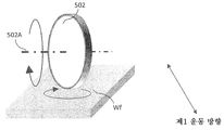
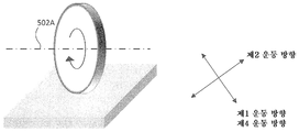
도 20은, 처리 대상물보다도 소직경의 연마 패드를 사용하여 연마 처리하기 위한 부분 연마 장치(1000)의 일례의 개략 구성을 나타내는 도면이다. 도 20에 도시된 부분 연마 장치(1000)에 있어서는, 처리 대상물인 기판 Wf보다도 소직경의 연마 패드(502)가 사용된다. 도 20에 도시한 바와 같이, 부분 연마 장치(1000)는, 기판 Wf가 설치되는 스테이지(400)와, 기판 Wf의 처리면에 처리를 행하기 위한 연마 패드(502)가 부착된 연마 헤드(500)와, 연마 헤드(500)를 보유 지지하는 아암(600)과, 처리액을 공급하기 위한 처리액 공급 계통(700)과, 연마 패드(502)의 컨디셔닝(드레싱)을 행하기 위한 컨디셔닝부(800)를 구비한다. 부분 연마 장치(1000)의 전체 동작은, 제어 장치(900)에 의해 제어된다. 도 20에 도시된 부분 연마 장치는, 처리액 공급계(700)로부터 DIW(순수), 세정 약액, 및 슬러리와 같은 연마액 등을 기판에 공급함과 함께, 연마 패드(502)를 회전시키면서 기판에 가압함으로써, 기판을 부분적으로 연마할 수 있다.20 is a diagram showing a schematic configuration of an example of the
도 20에 도시한 바와 같이, 연마 패드(502)는, 기판 Wf보다도 작은 치수이다. 여기서, 연마 패드(502)의 직경 Φ는 처리 대상인 막 두께·형상의 변동 영역과 동등 혹은 그보다 작다. 예를 들어, 연마 패드(502)의 직경 Φ는, 50㎜ 이하 또는 Φ10 내지 30㎜로 된다. 연마 패드(502)의 직경이 클수록 기판과의 면적비가 작아지기 때문에, 기판의 연마 속도는 증가한다. 한편, 원하는 처리 영역에 대한 연마의 정밀도에 대해서는, 반대로 연마 패드의 직경이 작아질수록, 정밀도가 향상된다. 이것은, 연마 패드의 직경이 작아질수록 단위 처리 면적이 작아지기 때문이다.As shown in Fig. 20, the
도 20에 도시된 부분 연마 장치(1000)에 있어서, 기판 Wf를 부분 연마할 때에는, 연마 패드(502)를 회전축(502A)을 중심으로 회전시키면서, 연마 패드(502)를 기판 Wf에 가압한다. 이때, 아암(600)에 기판 Wf의 반경 방향으로 요동시켜도 된다. 또한, 회전축(400A)을 중심으로 스테이지(400)를 회전시켜도 된다. 또한, 컨디셔닝부(800)는, 드레서(820)를 보유 지지하는 드레스 스테이지(810)를 구비한다. 드레스 스테이지(810)는, 회전축(810A)을 중심으로 회전 가능하다. 도 20의 부분 연마 장치(1000)에 있어서, 연마 패드(502)를 드레서(820)에 가압하고, 연마 패드(502) 및 드레서(820)를 회전시킴으로써, 연마 패드(502)의 컨디셔닝을 행할 수 있다. 도 20에 도시된 부분 연마 장치(1000)에 있어서, 제어 장치(900)에 의해, 스테이지(400)의 회전 속도, 연마 패드(502)의 회전 속도, 연마 패드(502)의 가압력, 아암(600)의 요동 속도, 처리액 공급 계통(700)으로부터의 처리액의 공급 및 처리 시간 등을 제어함으로써, 기판 Wf 위의 임의의 영역을 부분 연마할 수 있다.In the
도 20에 도시된 바와 같은 부분 연마 장치(1000)에 있어서는, 연마 패드(502)가 처리 대상물인 기판 Wf보다도 소직경이기 때문에, 대직경의 연마 패드를 사용하는 CMP 장치의 경우와 동일한 회전수로 소직경의 연마 패드(502)를 회전시킨 경우, 연마 패드(502)와 기판 Wf의 접촉 영역에서의 선속도는 저하되고, 나아가서는 연마 속도가 저하된다. 따라서, 대직경의 연마 패드를 사용하는 CMP 장치와 동일 정도의 연마 속도를 얻기 위해서는, 소직경의 연마 패드(502)를 대직경 CMP 장치의 경우보다도 매우 큰 회전수로 회전시킬 필요가 있다. 그러나, 그 경우, 연마 패드(502)가 고속으로 회전함으로써, 연마액을 연마 패드(502)의 외부로 배출하는 효과가 커지게 되어버려, 연마액의 연마 패드(502)의 기판 Wf와의 접촉면에 공급하는 것이 곤란해져서, 경우에 따라서는 연마 속도의 저하로 이어지는 경우도 있다.20, since the
또한, 도 20에 도시된 바와 같은 원판 형상의 연마 패드(502)를 사용하는 경우, 연마 패드(502)의 회전축이 기판 Wf의 표면에 대해서 수직이기 때문에, 연마 패드(502)를 회전시켜서 기판 Wf에 가압했을 때, 연마 패드(502)의 반경 방향으로 선속도 분포가 발생한다. 연마 패드(502)의 반경 방향으로 선속도 분포가 발생하면, 연마 패드(502)의 반경 방향으로 연마 속도 분포가 발생하게 된다. 그로 인해, 연마 패드(502)의 기판 Wf와의 접촉 면적에 대응하는 단위 가공흔 형상의 소정 형상에 대한 변동이 커지게 된다. 단위 가공흔 형상의 변동이 크면, 기판 Wf의 피가공 영역을 연마했을 때, 연마 후의 잔여막 변동으로 이어지기 때문에, 이와 같은 변동은 저감시키는 것이 바람직하다. 이와 같은 문제의 해결책으로서, 연마 패드(502)의 기판 Wf와의 접촉 면 내에 있어서 접촉 압력 또는 연마 패드(502)의 선속도에 분포를 갖게 함으로써, 단위 가공흔 형상의 소정 형상에 대한 변동을 저감시키는 방법이 있다. 그러나, 그를 위한 기구를 추가하기 위해서는, 연마 패드(502)가 어느 정도의 크기를 구비할 필요가 있어, 연마 패드(502)의 직경 축소화가 곤란해진다.20, since the rotation axis of the
본원에 있어서는, 단위 가공흔 형상의 소정 형상에 대한 변동을 저감할 수 있는 부분 연마 장치를 제공하는 것을 하나의 목적으로 하고 있다.It is an object of the present invention to provide a partial polishing apparatus capable of reducing variations in a predetermined shape of a unit processing pattern.
[형태 1] 형태 1에 의하면, 기판을 국소적으로 연마하기 위한 연마 장치가 제공되고, 이러한 연마 장치는, 기판에 접촉하는 가공면이 기판보다도 작은 연마 부재와, 상기 연마 부재를 기판에 가압시키기 위한 가압 기구와, 상기 연마 부재에, 기판의 표면에 평행한 제1 운동 방향으로 운동을 부여하기 위한 제1 구동 기구와, 상기 제1 운동 방향으로 수직이며 또한 기판의 표면에 평행한 방향으로 성분을 갖는 제2 운동 방향으로, 상기 연마 부재에 운동을 부여하기 위한 제2 구동 기구와, 연마 장치의 동작을 제어하기 위한 제어 장치를 갖고, 기판을 연마하고 있을 때, 상기 연마 부재는, 기판에 접촉하고 있는 영역 위의 임의의 점이 동일한 상기 제1 운동 방향으로 운동하도록 구성되고, 상기 제어 장치는, 상기 연마 부재를 사용하여 기판을 국소적으로 연마하도록, 상기 제1 구동 기구 및 제2 구동 기구의 동작을 제어하도록 구성된다. 형태 1에 의한 연마 장치에 의하면, 연마 부재를 기판에 가압하면서 제1 운동 방향으로 운동시켜 기판을 연마함과 함께, 제2 운동 방향으로 연마 부재를 이동시킴으로써, 가공흔 형상의 변동을 저감시킬 수 있다.According to a first aspect of the present invention, there is provided a polishing apparatus for locally polishing a substrate, the polishing apparatus comprising: an abrasive member having a processing surface in contact with the substrate, the abrasive member being smaller than the substrate; A first driving mechanism for applying a motion to the polishing member in a first direction of motion parallel to the surface of the substrate and a second driving mechanism for moving the substrate in a direction perpendicular to the first direction of movement and parallel to the surface of the substrate, A second driving mechanism for applying a motion to the polishing member in a second movement direction having a first direction of movement and a control device for controlling the operation of the polishing apparatus, And the control device is configured to move the substrate in the first direction of movement by locally polishing the substrate using the polishing member To, and is configured to control the operation of the first driving mechanism and second driving mechanism. According to the polishing apparatus of the first aspect, by moving the polishing member in the second movement direction while polishing the substrate by moving the polishing member in the first movement direction while pressing the polishing member against the substrate, variation of the processing trace shape can be reduced have.
[형태 2] 형태 2에 의하면, 형태 1에 의한 연마 장치에 있어서, 상기 제어 장치는, 상기 제1 운동 방향의 운동 속도를 기판의 연마 중에 변경하도록 구성된다.According to a second aspect of the present invention, in the polishing apparatus according to the first aspect, the control device is configured to change the moving speed in the first moving direction during polishing of the substrate.
[형태 3] 형태 3에 의하면, 형태 1 또는 형태 2에 기재된 연마 장치에 있어서, 상기 제2 운동 방향의 이동량은, 기판과 상기 연마 부재의 접촉 영역 중 제2 운동 방향의 성분의 길이 이하이다.According to a third aspect of the present invention, in the polishing apparatus according to the first or second aspect, the amount of movement in the second direction of movement is not more than the length of the component in the second direction of movement of the contact area between the substrate and the abrasive member.
[형태 4] 형태 4에 의하면, 형태 1 내지 형태 3 중 어느 하나의 형태에 있어서, 상기 연마 부재를 기판의 반경 방향으로 이동시키기 위한 제3 구동 기구를 갖는다.According to a fourth aspect of the present invention, in any one of the first to third aspects, the polishing apparatus has a third driving mechanism for moving the polishing member in the radial direction of the substrate.
[형태 5] 형태 5에 의하면, 형태 1 내지 형태 4 중 어느 하나의 형태에 있어서, 기판을 보유 지지하기 위한 스테이지와, 상기 스테이지를 운동시키기 위한 제4 구동 기구를 갖는다.According to a fifth aspect of the present invention, in any one of the first to fourth aspects, there is provided a stage for holding a substrate and a fourth driving mechanism for moving the stage.
[형태 6] 형태 6에 의하면, 형태 4를 인용하는 형태 5에 의한 연마 장치에 있어서, 상기 제2 구동 기구에 의해 발생하는 상기 제2 운동 방향에 있어서의 연마 부재의 운동 속도는, 상기 제3 구동 기구에 의한 연마 부재의 운동 속도, 및 상기 제4 구동 기구에 의한 상기 연마 부재에 대한 상기 스테이지의 운동 속도보다도 크다.According to a sixth aspect of the present invention, in the polishing apparatus according to the fifth aspect of the present invention, the moving speed of the polishing member in the second direction of motion generated by the second driving mechanism is the third The moving speed of the polishing member by the driving mechanism, and the moving speed of the stage with respect to the polishing member by the fourth driving mechanism.
[형태 7] 형태 7에 의하면, 형태 6에 의한 연마 장치에 있어서, 상기 스테이지의 운동은, 회전 운동, 각도 회전 운동, 및 직선 운동 중 어느 하나이다.Aspect 7 According to a seventh aspect of the present invention, in the polishing apparatus according to the sixth aspect, the movement of the stage is any one of a rotational motion, an angular rotational motion, and a linear motion.
[형태 8] 형태 8에 의하면, 형태 1 내지 형태 7 중 어느 하나의 형태에 따른 연마 장치에 있어서, 상기 제어 장치는, 기판의 피연마 영역에서의 목표 연마량을 계산하는 연산부를 갖고, 상기 연산부에 의해 계산된 목표 연마량에 따라서, 연마 장치를 제어하도록 구성된다.According to a eighth aspect of the present invention, in the polishing apparatus according to any one of the first to seventh aspects, the control device has an operation section for calculating a target polishing amount in a region to be polished of the substrate, To control the polishing apparatus in accordance with the target polishing amount calculated by the polishing apparatus.
[형태 9] 형태 9에 의하면, 형태 1 내지 형태 8 중 어느 하나의 형태에 따른 연마 장치에 있어서, 상기 연마 부재를 컨디셔닝하기 위한 컨디셔닝 부재를 갖는다.According to a ninth aspect of the present invention, in the polishing apparatus according to any one of the first to eighth aspects, the polishing apparatus has a conditioning member for conditioning the polishing member.
[형태 10] 형태 10에 의하면, 형태 9에 의한 연마 장치에 있어서, 상기 컨디셔닝 부재를 운동시키는 제5 구동 기구를 갖는다.Aspect 10 According to a tenth aspect of the present invention, in the polishing apparatus according to the ninth aspect, the fifth driving mechanism for moving the conditioning member is provided.
[형태 11] 형태 11에 의하면, 형태 5를 인용하는 형태 9에 따른 연마 장치에 있어서, 상기 컨디셔닝 부재는, 상기 스테이지의 밖에 배치된다.Aspect 11 According to a twelfth aspect of the present invention, in the polishing apparatus according to the ninth aspect, the conditioning member is disposed outside the stage.
[형태 12] 형태 12에 의하면, 형태 1 내지 형태 11 중 어느 하나의 형태에 따른 연마 장치에 있어서, 기판 위에 액체를 공급하기 위한 액체 공급 노즐을 갖는다.Aspect 12 According to a twelfth aspect of the present invention, in the polishing apparatus according to any one of the first to eleventh aspects, the liquid supply nozzle has a liquid supply nozzle for supplying liquid onto the substrate.
[형태 13] 형태 13에 의하면, 형태 12에 의한 연마 장치에 있어서, 상기 액체는, 연마제, 물, 및 세정 약액 중 적어도 하나를 포함한다.Mode 13 In Mode 13, in the polishing apparatus according to Mode 12, the liquid includes at least one of an abrasive, water, and a cleaning liquid.
[형태 14] 형태 14에 의하면, 형태 1 내지 형태 13 중 어느 하나의 형태에 따른 연마 장치에 있어서, 상기 제1 구동 기구는, 상기 연마 부재를 회전시키도록 구성된다.Aspect 14 According to a fourteenth aspect of the present invention, in the polishing apparatus according to any one of the first to thirteenth aspects, the first driving mechanism is configured to rotate the polishing member.
[형태 15] 형태 15에 의하면, 형태 14의 연마 장치에 있어서, 상기 연마 부재는 원판 형상이다.Aspect 15 According to a fifteenth aspect of the present invention, in the polishing apparatus according to the fourteenth aspect, the abrasive member has a disk shape.
[형태 16] 형태 16에 의하면, 형태 15의 연마 장치에 있어서, 원판 형상의 상기 연마 부재의 중심축이 기판의 표면에 평행하게 배치된다.Aspect 16 According to a sixteenth aspect of the present invention, in the polishing apparatus according to the fifteenth aspect, the center axis of the disc-like polishing member is disposed parallel to the surface of the substrate.
[형태 17] 형태 17에 의하면, 형태 14의 연마 장치에 있어서, 원판 형상의 상기 연마 부재의 중심축이 기판의 표면에 대해서 비평행하게 배치된다.According to a seventeenth aspect of the present invention, in the polishing apparatus according to form 14, the center axis of the disc-shaped polishing member is arranged so as to oppose the surface of the substrate.
[형태 18] 형태 18에 의하면, 형태 17의 연마 장치에 있어서, 상기 제1 구동 기구가 원판 형상의 상기 연마 부재를 회전시킬 때의 회전 중심축은, 원판 형상의 상기 연마 부재의 중심축으로부터 경사져 있다.Aspect 18 According to Mode 18, in the polishing apparatus according to Mode 17, the rotation center axis when the first driving mechanism rotates the disk-shaped polishing member is inclined from the central axis of the disc-like polishing member .
[형태 19] 형태 19에 의하면, 형태 14의 연마 장치에 있어서, 상기 연마 부재는 원기둥 형상이다.Mode 19 According to Mode 19, in the polishing apparatus of Mode 14, the polishing member has a cylindrical shape.
[형태 20] 형태 20에 의하면, 형태 19의 연마 장치에 있어서, 원기둥 형상의 상기 연마 부재의 중심축이 기판의 표면에 평행하게 배치된다.Aspect 20 According to Aspect 20, in the polishing apparatus according to Aspect 19, the central axis of the cylindrical polishing member is disposed parallel to the surface of the substrate.
[형태 21] 형태 21에 의하면, 형태 14의 연마 장치에 있어서, 상기 연마 부재는 구형상 또는 구형상의 일부를 구비하는 형상이다.Aspect 21 According to a twenty-first aspect of the present invention, in the polishing apparatus according to the fourteenth aspect, the abrasive member has a shape having a spherical or spherical shape.
[형태 22] 형태 22에 의하면, 형태 21의 연마 장치에 있어서, 상기 제2 구동 기구는, 상기 연마 부재의 외측에 위치하는 점을 중심으로 상기 연마 부재를 진자 운동시키도록 구성된다.Aspect 22 According to a twenty-second aspect of the invention, in the polishing apparatus according to the twenty-first aspect, the second driving mechanism is configured to cause the polishing member to pivot about a point located on the outer side of the polishing member.
[형태 23] 형태 23에 의하면, 형태 1 내지 형태 13 중 어느 하나의 형태의 연마 장치에 있어서, 상기 연마 부재는 평판 형상이다.Aspect 23: According to a twenty-third aspect of the present invention, in the polishing apparatus according to any one of the first aspect to the thirteenth aspect, the polishing member has a flat plate shape.
[형태 24] 형태 24에 의하면, 형태 23의 연마 장치에 있어서, 평판 형상의 상기 연마 부재는, 기판에 접촉하는 표면이 기판의 표면에 대해서 경사지도록 배치된다.Aspect 24 According to a twenty-fourth aspect of the present invention, in the polishing apparatus of the twenty-third aspect, the abrasive member having a flat plate shape is disposed so that the surface contacting the substrate is inclined with respect to the surface of the substrate.
[형태 25] 형태 25에 의하면, 형태 14의 연마 장치에 있어서, 상기 연마 부재는, 원추 형상 또는 원뿔대 형상이며, 상기 원추 형상 또는 상기 원뿔대 형상의 중심축은, 기판의 표면에 대해서 평행하게 배치된다.According to a twenty-fifth aspect of the invention, in the polishing apparatus according to form 14, the polishing member has a conical shape or a truncated conical shape, and the central axis of the conical shape or the truncated conical shape is arranged parallel to the surface of the substrate.
[형태 26] 형태 26에 의하면, 형태 14 내지 형태 25 중 어느 하나의 형태의 연마 조치에 있어서, 상기 제2 구동 기구는, 상기 연마 부재를 기판 위에서 직선 운동 또는 회전 운동시키도록 구성된다.Aspect 26 According to Mode 26, in the polishing action according to any one of Forms 14 to 25, the second driving mechanism is configured to linearly or rotationally move the polishing member above the substrate.
[형태 27] 형태 27에 의하면, 형태 1 내지 형태 13 중 어느 하나의 형태의 연마 장치에 있어서, 상기 연마 부재는, 벨트 부재를 갖고, 상기 제1 구동 기구는 벨트를 길이 방향으로 이동시키고, 상기 제2 구동 기구는, 벨트를 폭 방향으로 이동시키도록 구성된다.According to a twenty-seventh aspect of the present invention, in the polishing apparatus according to any one of the first to thirteenth aspects, the abrasive member has a belt member, the first driving mechanism moves the belt in the longitudinal direction, The second driving mechanism is configured to move the belt in the width direction.
[형태 28] 형태 28에 의하면, 기판 처리 시스템이 제공되고, 이러한 기판 처리 시스템은, 형태 1 내지 형태 27 중 어느 하나의 형태의 연마 장치와, 상기 연마 장치에 의해 연마한 기판을 세정하기 위한 세정 장치와, 상기 세정 장치에 의해 세정한 기판을 건조시키기 위한 건조 장치와, 상기 연마 장치, 상기 세정 장치, 및 상기 건조 장치의 사이에 기판을 반송하기 위한 반송 장치를 갖는다.According to a twenty-eighth aspect of the present invention, there is provided a substrate processing system comprising: a polishing apparatus according to any one of the first aspect to the twenty-seventh aspect; and a cleaning apparatus for cleaning the substrate polished by the polishing apparatus A drying device for drying the substrate cleaned by the cleaning device, and a transport device for transporting the substrate between the polishing device, the cleaning device, and the drying device.
[형태 29] 형태 29에 의하면, 형태 28에 기재된 기판 처리 시스템에 있어서, 또한, 기판에 접촉하는 가공면이 기판보다도 큰 연마 부재를 사용하여 기판을 연마하기 위한 대직경 연마 장치를 갖는다.Mode 29: According to Mode 29, in the substrate processing system according to
[형태 30] 형태 30에 의하면, 형태 28 또는 형태 29의 기판 처리 시스템에 있어서, 기판의 처리 전 및/또는 처리 후에, 기판의 표면 상태를 검출하기 위한 상태 검출부를 갖는다.Mode 30: According to Mode 30, in the substrate processing system of
[형태 31] 형태 31에 의하면, 형태 30의 기판 처리 시스템에 있어서, 상기 상태 검출부는, 기판의 표면에 형성되어 있는 막의 막 두께, 기판의 표면 단차, 및 이들에 상당하는 신호 중 적어도 하나에 관하여, 기판의 표면 내의 분포를 검출하도록 구성된다.Aspect 31: According to Mode 31, in the substrate processing system according to Mode 30, the state detecting portion detects at least one of a film thickness formed on the surface of the substrate, a surface step difference of the substrate, , And to detect the distribution within the surface of the substrate.
도 1은, 일 실시 형태에 따른 부분 연마 장치의 구성을 나타내는 개략도이다.
도 2는, 일 실시 형태에 따른 연마 헤드의 연마 패드를 보유 지지하는 기구를 나타내는 개략도이다.
도 3은, 일 실시 형태에 따른 부분 연마 장치의 구성을 나타내는 개략도이다.
도 4는, 도 1 및 도 3에 도시된 부분 연마 장치에 이용할 수 있는 연마 패드의 일례를 나타내는 도면이다.
도 5는, 도 1 및 도 3에 도시된 부분 연마 장치에 이용할 수 있는 연마 패드의 일례를 나타내는 도면이다.
도 6은, 도 1 및 도 3에 도시된 부분 연마 장치에 이용할 수 있는 연마 패드의 일례를 나타내는 도면이다.
도 7은, 도 1 및 도 3에 도시된 부분 연마 장치에 이용할 수 있는 연마 패드의 일례를 나타내는 도면이다.
도 8은, 도 1 및 도 3에 도시된 부분 연마 장치에 이용할 수 있는 연마 패드의 일례를 나타내는 도면이다.
도 9는, 도 1 및 도 3에 도시된 부분 연마 장치에 이용할 수 있는 연마 패드의 일례를 나타내는 도면이다.
도 10은, 도 1 및 도 3에 도시된 부분 연마 장치에 이용할 수 있는 연마 패드의 일례를 나타내는 도면이다.
도 11은, 도 1 및 도 3에 도시된 부분 연마 장치에 이용할 수 있는 연마 패드의 일례를 나타내는 도면이다.
도 12는, 도 1 및 도 3에 도시된 부분 연마 장치에 이용할 수 있는 연마 패드의 일례를 나타내는 도면이다.
도 13은, 도 1 및 도 3에 도시된 부분 연마 장치의 연마 패드 대신에 이용할 수 있는 연마 부재의 일례인 연마 벨트 부재를 나타내는 도면이다.
도 14는, 도 1 및 도 3에 도시된 부분 연마 장치에 이용할 수 있는 연마 패드의 일례를 나타내는 도면이다.
도 15는, 도 1 및 도 3에 도시된 부분 연마 장치에 이용할 수 있는 연마 패드의 일례를 나타내는 도면이다.
도 16은, 도 1 및 도 3에 도시된 부분 연마 장치에 이용할 수 있는 연마 패드의 일례를 나타내는 도면이다.
도 17은, 도 16에 도시된 연마 패드에 진자 운동을 부여하는 구동 기구를 나타내는 도면이다.
도 18a는, 일 실시 형태에 따른, 연마 패드의 제2 운동 방향의 이동량을 설명하기 위한 도면이다.
도 18b는, 일 실시 형태에 따른, 연마 패드의 제2 운동 방향의 이동량을 설명하기 위한 도면이다.
도 18c는, 일 실시 형태에 따른, 연마 패드의 제2 운동 방향의 이동량을 설명하기 위한 도면이다.
도 18d는, 일 실시 형태에 따른, 연마 패드의 제2 운동 방향의 이동량을 설명하기 위한 도면이다.
도 18e는, 일 실시 형태에 따른, 연마 패드의 제2 운동 방향의 이동량을 설명하기 위한 도면이다.
도 19a는, 일 실시 형태에 따른, 연마 패드의 제2 운동 방향으로의 이동과, 기판의 제4 운동 방향으로의 이동이 연마량에 미치는 영향을 설명하는 도면이다.
도 19b는, 일 실시 형태에 따른, 연마 패드의 제2 운동 방향으로의 이동과, 기판의 제4 운동 방향으로의 이동이 연마량에 미치는 영향을 설명하는 도면이다.
도 19c는, 일 실시 형태에 따른, 연마 패드의 제2 운동 방향으로의 이동과, 기판의 제4 운동 방향으로의 이동이 연마량에 미치는 영향을 설명하는 도면이다.
도 20은, 처리 대상물보다도 소직경의 연마 패드를 사용하여 연마 처리하기 위한 부분 연마 장치의 일례의 개략 구성을 나타내는 도면이다.
도 21a는, 일 실시 형태에 따른 부분 연마 장치를 사용한 연마 제어의 일례를 설명하는 개략도이다.
도 21b는, 일 실시 형태에 따른 부분 연마 장치를 사용한 연마 제어의 일례를 설명하는 개략도이다.
도 22a는, 일 실시 형태에 따른, 기판의 막 두께나 요철·높이에 관련된 정보를 처리하기 위한 제어 회로의 예를 나타내는 도면이다.
도 22b는, 도 22a에 도시된 부분 연마용 제어부로부터 기판 표면의 상태 검출부를 분할했을 때의 회로도를 나타낸다.
도 23은, 일 실시 형태에 따른, 부분 연마 장치를 탑재한 기판 처리 시스템을 나타내는 개략도이다.BRIEF DESCRIPTION OF THE DRAWINGS FIG. 1 is a schematic view showing a configuration of a partial polishing apparatus according to an embodiment; FIG.
2 is a schematic view showing a mechanism for holding a polishing pad of a polishing head according to an embodiment.
3 is a schematic view showing a configuration of a partial polishing apparatus according to an embodiment.
Fig. 4 is a view showing an example of a polishing pad usable in the partial polishing apparatus shown in Figs. 1 and 3. Fig.
Fig. 5 is a view showing an example of a polishing pad usable in the partial polishing apparatus shown in Figs. 1 and 3. Fig.
Fig. 6 is a view showing an example of a polishing pad usable in the partial polishing apparatus shown in Figs. 1 and 3. Fig.
Fig. 7 is a view showing an example of a polishing pad usable in the partial polishing apparatus shown in Figs. 1 and 3. Fig.
Fig. 8 is a view showing an example of a polishing pad usable in the partial polishing apparatus shown in Figs. 1 and 3. Fig.
Fig. 9 is a view showing an example of a polishing pad usable in the partial polishing apparatus shown in Figs. 1 and 3. Fig.
Fig. 10 is a view showing an example of a polishing pad usable in the partial polishing apparatus shown in Figs. 1 and 3. Fig.
Fig. 11 is a view showing an example of a polishing pad usable in the partial polishing apparatus shown in Figs. 1 and 3. Fig.
Fig. 12 is a view showing an example of a polishing pad usable in the partial polishing apparatus shown in Figs. 1 and 3. Fig.
13 is a view showing an abrasive belt member which is an example of an abrasive member usable in place of the abrasive pad of the partial abrasive apparatus shown in Figs. 1 and 3. Fig.
14 is a view showing an example of a polishing pad usable in the partial polishing apparatus shown in Figs. 1 and 3. Fig.
Fig. 15 is a view showing an example of a polishing pad usable in the partial polishing apparatus shown in Figs. 1 and 3. Fig.
16 is a view showing an example of a polishing pad usable in the partial polishing apparatus shown in Figs. 1 and 3. Fig.
17 is a view showing a drive mechanism for imparting pendulum motion to the polishing pad shown in Fig.
18A is a diagram for explaining the amount of movement of the polishing pad in the second direction of movement according to one embodiment.
FIG. 18B is a view for explaining the movement amount of the polishing pad in the second movement direction, according to one embodiment. FIG.
18C is a view for explaining the movement amount of the polishing pad in the second movement direction, according to one embodiment.
FIG. 18D is a view for explaining the movement amount of the polishing pad in the second movement direction, according to one embodiment. FIG.
18E is a diagram for explaining the movement amount of the polishing pad in the second movement direction, according to one embodiment.
19A is a view for explaining the influence of the movement of the polishing pad in the second movement direction and the movement of the substrate in the fourth movement direction on the polishing amount, according to one embodiment.
Fig. 19B is a view for explaining the influence of the movement of the polishing pad in the second movement direction and the movement of the substrate in the fourth movement direction on the polishing amount, according to one embodiment. Fig.
FIG. 19C is a view for explaining the effect of the movement of the polishing pad in the second movement direction and the movement of the substrate in the fourth movement direction on the polishing amount, according to one embodiment. FIG.
20 is a view showing a schematic configuration of an example of a partial polishing apparatus for performing a polishing process using a polishing pad having a smaller diameter than an object to be processed.
21A is a schematic view for explaining an example of polishing control using the partial polishing apparatus according to one embodiment.
21B is a schematic view for explaining an example of polishing control using the partial polishing apparatus according to one embodiment.
FIG. 22A is a diagram showing an example of a control circuit for processing information relating to the film thickness, ruggedness, and height of a substrate according to an embodiment. FIG.
22B shows a circuit diagram when the state detecting section on the surface of the substrate is divided from the partial polishing control section shown in Fig. 22A.
23 is a schematic view showing a substrate processing system equipped with a partial polishing apparatus according to an embodiment.
이하에, 본 발명에 따른 부분 연마 장치의 실시 형태를 첨부 도면과 함께 설명한다. 첨부 도면에 있어서, 동일하거나 또는 유사한 요소에는 동일하거나 또는 유사한 참조 부호가 부여되고, 각 실시 형태의 설명에 있어서 동일하거나 또는 유사한 요소에 관한 중복되는 설명은 생략하는 경우가 있다. 또한, 각 실시 형태에서 나타내는 특징은, 서로 모순되지 않는 한 다른 실시 형태에도 적용 가능하다.Hereinafter, embodiments of the partial polishing apparatus according to the present invention will be described with reference to the accompanying drawings. In the accompanying drawings, the same or similar elements are denoted by the same or similar reference numerals, and redundant explanations on the same or similar elements in the description of the respective embodiments may be omitted. The features shown in the embodiments can be applied to other embodiments as long as they are not contradictory to each other.
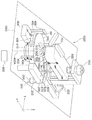
도 1은, 일 실시 형태에 따른 부분 연마 장치(1000)의 구성을 나타내는 개략도이다. 도 1에 도시된 바와 같이, 부분 연마 장치(1000)는, 베이스면(1002) 위에 구성되어 있다. 부분 연마 장치(1000)는, 독립된 하나의 장치로서 구성해도 되고, 또한, 부분 연마 장치(1000)와 함께 대직경의 연마 패드를 사용하는 대직경 연마 장치(1200)를 포함하는 기판 처리 시스템(1100)의 일부 모듈로서 구성해도 된다(도 23 참조). 부분 연마 장치(1000)는, 도시하지 않은 하우징 내에 설치된다. 하우징은 도시하지 않은 배기 기구를 구비하고, 연마 처리 중에 연마액 등이 하우징의 외부로 노출되지 않도록 구성된다.1 is a schematic view showing a configuration of a
도 1에 도시된 바와 같이, 부분 연마 장치(1000)는, 기판 Wf를 상부 방향으로 보유 지지하는 스테이지(400)를 구비한다. 일 실시 형태에 있어서, 기판 Wf는, 도시하지 않은 반송 장치에 의해 스테이지(400)에 배치할 수 있다. 도시의 부분 연마 장치(1000)는, 스테이지(400)의 주위에, 상하 이동이 가능한 4개의 리프트 핀(402)을 구비하고 있으며, 리프트 핀(402)이 상승한 상태에 있어서, 반송 장치로부터 4개의 리프트 핀(402) 위에서 기판 Wf를 수취할 수 있다. 리프트 핀(402) 위에 기판 Wf가 적재된 후, 리프트 핀(402)은, 스테이지(400)로의 기판 수수 위치까지 하강함으로써, 기판 Wf가 스테이지에 임시 적치된다. 그로 인해, 4개의 리프트 핀(402)의 내측에 제한된 영역 내에 기판 Wf를 위치 결정이 가능하다. 그러나, 또한 고정밀도의 위치 결정을 요하는 경우에는, 별도로 위치 결정 기구(404)에 의해, 스테이지(400) 위의 소정 위치에 기판 Wf를 위치 결정해도 된다. 도 1에 도시된 실시 형태에 있어서는, 위치 결정 핀(도시생략)과 위치 결정 패드(406)에 의해 기판 Wf의 위치 결정이 가능하다. 위치 결정 기구(404)는, 기판 Wf의 평면 내의 방향으로 이동 가능한 위치 결정 패드(406)를 구비한다. 스테이지(400)를 사이에 두고, 위치 결정 패드(406)의 반대측에 복수의 위치 결정 핀(도시생략)을 구비하고 있다. 리프트 핀(402) 위에 기판 Wf가 적재된 상태에 있어서, 위치 결정 패드(406)를 기판 Wf에 가압하고, 위치 결정 패드(406)와 위치 결정 핀에 의해 기판 Wf의 위치 결정을 행할 수 있다. 기판 Wf의 위치 결정을 하면, 기판 Wf를 스테이지(400) 위에 고정하고, 그 후, 리프트 핀(402)을 하강시켜서 기판 Wf를 스테이지(400)의 위에 배치할 수 있다. 스테이지(400)는, 예를 들어 진공 흡착에 의해 기판 Wf를 스테이지(400) 위에 고정하도록 할 수 있다. 부분 연마 장치(1000)는, 검출부(408)를 구비한다. 검출부(408)는, 스테이지(400) 위에 배치된 기판 Wf의 위치를 검출하기 위한 것이다. 예를 들어, 기판 Wf에 형성된 노치, 오리엔테이션 플랫이나 기판 외주부를 검출하여, 기판 Wf의 스테이지(400) 위에서의 위치를 검출할 수 있다. 노치나 오리엔테이션 플랫의 위치를 기준으로 함으로써, 기판 Wf가 임의의 점을 특정하는 것이 가능하며, 그것에 의해 원하는 영역의 부분 연마가 가능해진다. 또한, 기판 외주부의 위치 정보보다, 기판 Wf의 스테이지(400) 위에서의 위치 정보(예를 들어, 이상 위치에 대한 어긋남량)가 얻어지는 점에서, 본 정보를 기초로 제어 장치(900)에 의해 연마 패드(502)의 이동 위치를 보정해도 된다. 또한, 기판 Wf를 스테이지(400)로부터 이탈시킬 때에는, 리프트 핀(402)을 스테이지(400)로부터의 기판 수취 위치로 이동한 후, 스테이지(400)의 진공 흡착을 해방한다. 그리고, 리프트 핀(402)을 상승시켜서, 기판 Wf를 반송 장치로의 기판 수수 위치로 이동시킨 후, 리프트 핀(402)의 기판 Wf를 도시하지 않은 반송 장치가 수취할 수 있다. 기판 Wf는 그 후, 반송 장치에 의해 후속의 처리를 위해 임의의 장소로 반송할 수 있다.As shown in Fig. 1, the
부분 연마 장치(1000)의 스테이지(400)는 회전 구동 기구(410)를 구비하고, 회전축(400A)을 중심으로 회전 가능 및/또는 각도 회전 가능하게 구성된다. 여기서, 「회전」이란, 일정한 방향으로 연속적으로 회전하는 것을 의미하고 있으며, 「각도 회전」이란, 소정의 각도 범위에서 원주 방향으로 운동(왕복 운동도 포함함)하는 것을 의미하고 있다. 또한, 다른 실시 형태로서, 스테이지(400)는, 보유 지지된 기판 Wf에 직선 운동을 부여하는 이동 기구를 구비하도록 해도 된다.The
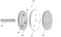
도 1에 도시된 부분 연마 장치(1000)는, 연마 헤드(500)를 구비한다. 연마 헤드(500)는, 연마 패드(502)를 보유 지지한다. 도 2는, 연마 헤드(500)의 연마 패드(502)를 보유 지지하는 기구를 나타내는 개략도이다. 도 2에 도시된 바와 같이, 연마 헤드(500)는, 제1 보유 지지 부재(504) 및 제2 보유 지지 부재(506)를 구비한다. 연마 패드(502)는, 제1 보유 지지 부재(504)와 제2 보유 지지 부재(506)의 사이에 보유 지지된다. 도시한 바와 같이, 제1 보유 지지 부재(504), 연마 패드(502) 및 제2 보유 지지 부재(506)는, 모두 원판 형상이다. 제1 보유 지지 부재(504) 및 제2 보유 지지 부재(506)의 직경은, 연마 패드(502)의 직경보다도 작다. 그로 인해, 연마 패드(502)가 제1 보유 지지 부재(504) 및 제2 보유 지지 부재(506)에 보유 지지된 상태에서, 연마 패드(502)가 제1 보유 지지 부재(504) 및 제2 보유 지지 부재(506)의 테두리부로부터 노출된다. 또한, 제1 보유 지지 부재(504), 연마 패드(502), 및 제2 보유 지지 부재(506)는, 모두 중심에 개구부를 구비하고, 이러한 개구부에 회전 샤프트(510)가 삽입된다. 제1 보유 지지 부재(504)의 연마 패드(502)측의 면에는, 연마 패드(502)측에 돌출되는 1개 또는 복수 개의 가이드 핀(508)이 설치되어 있다. 한편, 연마 패드(502)에 있어서의 가이드 핀(508)에 대응하는 위치에는 관통 구멍이 설치되고, 또한, 제2 보유 지지 부재(506)의 연마 패드(502)측의 면에는, 가이드 핀(508)을 받아들이는 오목부가 형성되어 있다. 그로 인해, 회전 샤프트(510)에 의해 제1 보유 지지 부재(504) 및 제2 보유 지지 부재(506)를 회전시켰을 때, 연마 패드(502)가 미끄러지지 않고 보유 지지 부재(504, 506)와 일체적으로 회전할 수 있다.The
도 1에 도시된 실시 형태에 있어서는, 연마 헤드(500)는, 연마 패드(502)의 원판 형상의 측면이 기판 Wf를 향하도록 연마 패드(502)를 보유 지지한다. 또한, 연마 패드(502)의 형상은 원판 형상으로 한정되지 않는다. 다른 형상의 연마 패드(502)에 대해서는 후술한다. 도 1에 도시된 부분 연마 장치(1000)는, 연마 헤드(500)를 보유 지지하는 보유 지지 아암(600)을 구비한다. 보유 지지 아암(600)은, 연마 패드(502)에 기판 Wf에 대해서 제1 운동 방향으로 운동을 부여하기 위한 제1 구동 기구를 구비한다. 여기에서 말하는 「제1 운동 방향」은, 기판 Wf를 연마하기 위한 연마 패드(502)의 운동이며, 도 1의 부분 연마 장치(1000)에 있어서는, 연마 패드(502)의 회전 운동이다. 그로 인해, 제1 구동 기구는 예를 들어 일반적인 모터로 구성할 수 있다. 기판 Wf와 연마 패드(502)의 접촉 부분에 있어서는, 연마 패드(502)는, 기판 Wf의 표면에 평행[연마 패드(502)의 접선 방향; 도 1에 있어서는 x방향]하게 이동하므로, 연마 패드(502)의 회전 운동이더라도, 「제1 운동 방향」은, 일정한 직선 방향이라고 생각할 수 있다.In the embodiment shown in Fig. 1, the polishing
전술한 도 20에 도시된 부분 연마 장치(1000)에 있어서는, 연마 패드(502)는, 원판 형상이며, 회전축은 기판 Wf의 표면에 수직이다. 그로 인해, 전술한 바와 같이 연마 패드(502)의 반경 방향으로 선속도 분포가 발생하여, 연마 패드(502)의 반경 방향으로 연마 속도 분포가 발생하게 된다. 그로 인해, 도 20에 도시된 부분 연마 장치(1000)에 있어서는, 연마 패드(502)의 기판 Wf와의 접촉 면적에 대응하는 단위 가공흔 형상의 소정 형상에 대한 변동이 커지게 된다. 그러나, 도 1에 도시된 부분 연마 장치(1000)에 있어서는, 연마 패드(502)의 회전축은 기판 Wf의 표면에 평행하며, 연마 패드(502)의 기판 Wf와의 접촉 영역에 있어서 선속도는 일정하다. 그로 인해, 도 1의 실시 형태에 따른 부분 연마 장치(1000)에 있어서는, 연마 패드(502)의 기판 Wf와의 접촉 영역에 있어서, 선속도 분포로부터 발생하는 연마 속도의 변동은, 도 20에 도시된 부분 연마 장치(1000)의 경우보다도 작다. 그로 인해, 도 1의 부분 연마 장치(1000)에 있어서는, 단위 가공흔 형상의 소정 형상에 대한 변동이 저감된다. 또한, 도 1에 도시된 부분 연마 장치(1000)에 있어서는, 연마 패드(502)의 회전축이 기판 Wf의 표면에 평행하기 때문에, 도 20에 도시된 부분 연마 장치(1000)의 경우와는 달리, 연마 패드(502)의 기판 Wf와의 접촉 영역의 미소화가 용이하다. 연마 패드(502)와 기판 Wf의 접촉 영역의 미소화가 가능하게 됨으로써, 예를 들어 연마 패드(502)의 직경을 크게 함으로써, 연마 패드(502)와 기판 Wf의 상대 선속도를 증가시키는 것이 가능하며, 나아가서는 연마 속도를 크게 하는 것이 가능하다. 또한, 연마 패드(502)와 기판 Wf의 접촉 영역은, 연마 패드(502)의 직경 및 두께로 결정된다. 일례로서, 연마 패드(502)의 직경 Φ는, 약 50㎜ 내지 약 300㎜, 연마 패드(502)의 두께는 약 1㎜ 내지 약 10㎜ 정도의 범위에서 조합해도 된다. In the above-described
일 실시 형태로서, 제1 구동 기구는, 연마 중에 연마 패드(502)의 회전 속도를 변경할 수 있다. 회전 속도를 변경함으로써, 연마 속도의 조정이 가능하며, 따라서 기판 Wf 위의 피처리 영역에서의 필요 연마량이 큰 경우에 있어서도, 효율적으로 연마가 가능하다. 또한, 예를 들어 연마 중에 있어서 연마 패드(502)의 감모가 커서, 연마 패드(502)의 직경에 변화가 발생한 경우라도, 회전 속도의 조정을 행함으로써, 연마 속도를 유지하는 것이 가능하다. 또한, 도 1에 도시된 실시 형태에 있어서는, 제1 구동 기구는, 원판 형상의 연마 패드(502)에 회전 운동을 부여하는 것이지만, 다른 실시 형태에 있어서는, 연마 패드(502)의 형상으로서 다른 형상을 이용할 수도 있고, 또한, 제1 구동 기구는 연마 패드(502)에 직선 운동을 부여하도록 하여 구성할 수도 있다. 또한, 직선 운동에는 직선적인 왕복 운동도 포함하도록 한다.In one embodiment, the first driving mechanism can change the rotational speed of the
도 1에 도시된 부분 연마 장치(1000)는, 보유 지지 아암(600)을 기판 Wf의 표면에 수직인 방향(도 1에 있어서는 z 방향)으로 이동시키기 위한 수직 구동 기구(602)를 구비한다. 수직 구동 기구(602)에 의해, 보유 지지 아암(600)과 함께 연마 헤드(500) 및 연마 패드(502)가 기판 Wf의 표면에 수직인 방향으로 이동 가능하게 된다. 수직 구동 기구(602)는, 기판 Wf를 부분 연마할 때 기판 Wf에 연마 패드(502)를 가압하기 위한 가압 기구로서도 기능한다. 도 1에 도시된 실시 형태에 있어서는, 수직 구동 기구(602)는, 모터 및 볼 나사를 이용한 기구이지만, 다른 실시 형태로서, 공기 압력식 또는 액압식의 구동 기구나 스프링을 이용한 구동 기구로 해도 된다. 또한, 일 실시 형태로서, 연마 헤드(500)를 위한 수직 구동 기구(602)로서, 조동용과 미동용으로 서로 다른 구동 기구를 사용해도 된다. 예를 들어, 조동용 구동 기구는 모터를 이용한 구동 기구로 하고, 연마 패드(502)의 기판 Wf에 대한 가압을 행하는 미동용 구동 기구는 에어 실린더를 사용한 구동 기구로 할 수 있다. 이 경우, 연마 패드(502)의 가압력을 감시하면서, 에어 실린더 내의 공기압을 조정함으로써 연마 패드(502)의 기판 Wf에 대한 가압력을 제어할 수 있다. 또한, 반대로, 조동용 구동 기구로서 에어 실린더를 이용하고, 미동용 구동 기구로서 모터를 이용해도 된다. 이 경우, 미동용 모터의 토크를 감시하면서 모터를 제어함으로써, 연마 패드(502)의 기판 Wf에 대한 가압력을 제어할 수 있다. 또한, 다른 구동 기구로서 피에조 소자를 사용해도 되며, 피에조 소자에 인가하는 전압으로 이동량을 조정할 수 있다. 또한, 수직 구동 기구(602)를 미동용과 조동용으로 나눌 경우, 미동용 구동 기구는, 보유 지지 아암(600)의 연마 패드(502)를 보유 지지하고 있는 위치, 즉 도 1의 예에서는 아암(600)의 선단에 설치하도록 해도 된다.The
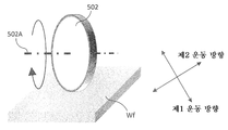
도 1에 도시된 부분 연마 장치(1000)에 있어서는, 보유 지지 아암(600)을 가로 방향(도 1에 있어서는 y방향)으로 이동시키기 위한 가로 구동 기구(620)를 구비한다. 가로 구동 기구(620)에 의해, 아암(600)과 함께 연마 헤드(500) 및 연마 패드(502)가 가로 방향으로 이동 가능하다. 또한, 이러한 가로 방향(y방향)은, 전술한 제1 운동 방향으로 수직이며 또한 기판의 표면에 평행한 제2 운동 방향이다. 그로 인해, 부분 연마 장치(1000)는, 제1 운동 방향(x방향)으로 연마 패드(502)를 이동시켜 기판 Wf를 연마하면서, 동시에 직교하는 제2 운동 방향(y방향)으로 연마 패드(502)를 운동시킴으로써, 기판 Wf의 가공흔 형상을 보다 균일화시키는 것이 가능해진다. 전술한 바와 같이, 도 1에 도시된 부분 연마 장치(1000)에 있어서는, 연마 패드(502)의 기판 Wf와의 접촉 영역에서는, 선속도는 일정하다. 그러나, 연마 패드(502)의 형상이나 재질에 불균일이 있거나 함으로써, 연마 패드(502)의 기판과의 접촉 상태가 불균일하거나 하면, 기판 Wf의 가공흔 형상, 특히 연마 패드(502)의 기판 Wf와의 접촉면에 있어서 제1 운동 방향과 수직인 방향으로 연마 속도의 변동이 발생한다. 그러나, 연마 중에 연마 패드(502)를 제1 운동 방향과 수직인 방향으로 운동시킴으로써, 연마 변동을 완화하는 것이 가능하며, 따라서 가공흔 형상을 보다 균일하게 할 수 있다. 또한, 도 1에 도시된 실시 형태에 있어서는, 수직 구동 기구(602)는, 모터 및 볼 나사를 이용한 기구이다. 또한, 도 1에 도시된 실시 형태에 있어서는, 가로 구동 기구(620)는 보유 지지 아암(600)을 수직 구동 기구(602)마다 이동시키는 구성이다. 또한, 제2 운동 방향은, 제1 운동 방향에 대하여 엄밀하게 수직이 아니더라도, 제1 운동 방향으로 수직인 성분을 갖는 방향이면, 가공흔 형상을 균일하게 하는 효과를 발휘할 수 있다.In the
도 1에 도시된 실시 형태에 따른 부분 연마 장치(1000)는, 연마액 공급 노즐(702)을 구비한다. 연마액 공급 노즐(702)은, 연마액, 예를 들어 슬러리의 공급원(710)(도 20 참조)에 유체적으로 접속되어 있다. 또한, 도 1에 도시된 실시 형태에 따른 부분 연마 장치(1000)에 있어서는, 연마액 공급 노즐(702)은, 보유 지지 아암(600)에 보유 지지되어 있다. 그로 인해, 연마액 공급 노즐(702)을 통하여, 기판 Wf 위의 연마 영역에만 연마액을 효율적으로 공급할 수 있다.The
도 1에 도시된 실시 형태에 따른 부분 연마 장치(1000)는, 기판 Wf를 세정하기 위한 세정 기구(200)를 구비한다. 도 1에 도시된 실시 형태에 있어서, 세정 기구(200)는, 세정 헤드(202), 세정 부재(204), 세정 헤드 보유 지지 아암(206), 및 린스 노즐(208)을 구비한다. 세정 부재(204)는, 기판 Wf에 회전시키면서 접촉시켜 부분 연마 후의 기판 Wf를 세정하기 위한 부재이다. 세정 부재(204)는, 일 실시 형태로서 PVA 스펀지로부터 형성할 수 있다. 그러나, 세정 부재(204)는, PVA 스펀지 대신에, 혹은 추가적으로 메가소닉 세정, 고압수 세정, 이류체 세정을 실현하기 위한 세정 노즐을 구비하도록 할 수도 있다. 세정 부재(204)는, 세정 헤드(202)에 보유 지지된다. 또한, 세정 헤드(202)는, 세정 헤드 보유 지지 아암(206)에 보유 지지된다. 세정 헤드 보유 지지 아암(206)은, 세정 헤드(202) 및 세정 부재(204)를 회전시키기 위한 구동 기구를 구비한다. 이러한 구동 기구는, 예를 들어 모터 등으로 구성할 수 있다. 또한, 세정 헤드 보유 지지 아암(206)은, 기판 Wf의 면 내를 요동하기 위한 요동 기구를 구비한다. 세정 기구(200)는, 린스 노즐(208)을 구비한다. 린스 노즐(208)에는, 도시하지 않은 세정액 공급원에 접속되어 있다. 세정액은, 예를 들어 순수, 약액 등으로 할 수 있다. 도 1의 실시 형태에 있어서, 린스 노즐(208)은, 세정 헤드 보유 지지 아암(206)에 부착해도 된다. 린스 노즐(208)은, 세정 헤드 보유 지지 아암(206)에 보유 지지된 상태에서 Wf의 면 내에서 요동하기 위한 요동 기구를 구비한다.The
도 1에 도시된 실시 형태에 따른 부분 연마 장치(1000)는, 연마 패드(502)의 컨디셔닝을 행하기 위한 컨디셔닝부(800)를 구비한다. 컨디셔닝부(800)는, 스테이지(400)의 밖에 배치되어 있다. 컨디셔닝부(800)는, 드레서(820)를 보유 지지하는 드레스 스테이지(810)를 구비한다. 도 1의 실시 형태에 있어서, 드레스 스테이지(810)는, 회전축(810A)을 중심으로 회전 가능하다. 도 1의 부분 연마 장치(1000)에 있어서, 연마 패드(502)를 드레서(820)에 가압하고, 연마 패드(502) 및 드레서(820)를 회전시킴으로써, 연마 패드(502)의 컨디셔닝을 행할 수 있다. 또한, 다른 실시 형태로서, 드레스 스테이지(810)는, 회전 운동이 아니라, 직선 운동(왕복 운동을 포함함)을 하도록 구성해도 된다. 또한, 도 1의 부분 연마 장치(1000)에 있어서, 컨디셔닝부(800)는, 주로 기판 Wf의 어떤 점에 있어서의 부분 연마를 종료하고, 다음 점 혹은 다음 기판의 부분 연마를 행하기 전에 연마 패드(502)를 컨디셔닝하기 위해서 사용한다. 여기서, 드레서(820)는, 예를 들어 (1) 표면에 다이아몬드의 입자가 전착 고정된 다이아드레서, (2) 다이아몬드 지립이 연마 패드와의 접촉면의 전체면 혹은 일부에 배치된 다이아드레서, 및 (3) 수지제의 브러시모가 연마 패드와의 접촉면의 전체면 혹은 일부에 배치된 브러시 드레서, (4) 이들 중 어느 하나 또는 이들의 임의의 조합으로 형성할 수 있다.The
도 1에 도시된 실시 형태에 따른 부분 연마 장치(1000)는, 제2 컨디셔너(850)를 구비한다. 제2 컨디셔너(850)는, 연마 패드(502)에 의해 기판 Wf를 한창 연마하고 있는 동안에 연마 패드(502)를 컨디셔닝하기 위한 것이다. 그로 인해, 제2 컨디셔너(850)는, in-situ 컨디셔너라고 할 수도 있다. 제2 컨디셔너(850)는, 연마 패드(502)의 근방에서 보유 지지 아암(600)에 보유 지지된다. 제2 컨디셔너(850)는, 연마 패드(502)에 대해서 컨디셔닝 부재(852)를 가압하는 방향으로 컨디셔닝 부재(852)를 이동시키기 위한 이동 기구를 구비한다. 도 1의 실시 형태에 있어서는, 컨디셔닝 부재(852)는, 연마 패드(502)의 근방에서 연마 패드(502)로부터 x방향으로 이격하여 보유 지지되어 있으며, 이동 기구에 의해 컨디셔닝 부재(852)를 x방향으로 이동 가능하게 구성되어 있다. 또한, 컨디셔닝 부재(852)는, 도시하지 않은 구동 기구에 의해, 회전 운동 또는 직선 운동이 가능하게 구성된다. 그로 인해, 연마 패드(502)에 의해 기판 Wf를 연마하고 있을 때, 컨디셔닝 부재(852)를 회전 운동 등을 시키면서 연마 패드(502)에 가압 접촉시킴으로써, 기판 Wf의 연마 중에 연마 패드(502)를 컨디셔닝할 수 있다.The
도 1에 도시된 실시 형태에 있어서, 부분 연마 장치(1000)는, 제어 장치(900)를 구비한다. 부분 연마 장치(1000)의 각종 구동 기구는 제어 장치(900)에 접속되어 있으며, 제어 장치(900)는, 부분 연마 장치(1000)의 동작을 제어할 수 있다. 또한, 제어 장치는, 기판 Wf의 피연마 영역에서의 목표 연마량을 계산하는 연산부를 구비한다. 제어 장치(900)는, 연산부에 의해 계산된 목표 연마량에 따라서, 연마 장치를 제어하도록 구성된다. 또한, 제어 장치(900)는, 기억 장치, CPU, 입출력 기구 등을 구비하는 일반적인 컴퓨터에 소정의 프로그램을 인스톨함으로써 구성할 수 있다.In the embodiment shown in Fig. 1, the
또한, 일 실시 형태에 있어서, 부분 연마 장치(1000)는, 도 1, 3에 도시는 하지 않았지만, 기판 Wf의 피연마면의 상태를 검출하기 위한 상태 검출부(420)(도 22a, 도 23b 등)를 구비해도 된다. 상태 검출부는, 일례로서 Wet-ITM(In-line Thickness Monitor)(420)으로 할 수 있다. Wet-ITM(420)에서는, 검출 헤드가 기판 Wf 위에 비접촉 상태에서 존재하고, 기판 Wf의 전체면을 이동함으로써, 기판 Wf 위에 형성된 막의 막 두께 분포(또는 막 두께에 관련된 정보의 분포)를 검출(측정)할 수 있다. 또한, 상태 검출부(420)로서 Wet-ITM 이외에도 임의의 방식의 검출기를 사용할 수 있다. 예를 들어, 이용 가능한 검출 방식으로서는, 공지된 와전류식이나 광학식과 같은 비접촉식의 검출 방식을 채용할 수 있고, 또한 접촉식의 검출 방식을 채용해도 된다. 접촉식의 검출 방식으로서는, 예를 들어 통전 가능한 프로브를 구비한 검출 헤드를 준비하고, 기판 Wf에 프로브를 접촉시켜 통전시킨 상태에서 기판 Wf면 내를 주사시킴으로써, 막 저항의 분포를 검출하는 전기 저항식의 검출을 채용할 수 있다. 또한, 다른 접촉식의 검출 방식으로서, 기판 Wf의 표면에 프로브를 접촉시킨 상태에서 기판 Wf면 내를 주사시켜, 프로브의 상하 이동을 모니터링함으로써 표면의 요철 분포를 검출하는 단차 검출 방식을 채용할 수도 있다. 접촉식 및 비접촉식의 어느 검출 방식에 있어서도, 검출되는 출력은 막 두께 혹은 막 두께에 상당하는 신호이다. 광학식의 검출에 있어서는, 기판 Wf의 표면에 투광한 광의 반사광량 외에, 기판 Wf 표면의 색조 차이보다 막 두께 차이를 인식해도 된다. 또한, 기판 Wf 위의 막 두께의 검출 시에는, 기판 Wf를 회전시키면서, 또한 검출기는 반경 방향으로 요동시키면서 막 두께를 검출하는 것이 바람직하다. 이에 의해 기판 Wf 전체면에 있어서의 막 두께나 단차 등의 표면 상태의 정보를 얻는 것이 가능하게 된다. 또한, 검출부(408)에 의해 검출되는 노치나 오리엔테이션 플랫 위치를 기준으로 함으로써, 막 두께 등의 데이터를 반경 방향의 위치뿐만 아니라, 주위 방향의 위치와도 관련짓는 것이 가능하며, 이에 의해, 기판 Wf 위의 막 두께나 단차 또는 그들에 관련된 신호의 분포를 얻는 것이 가능하게 된다. 또한, 부분 연마를 행할 때, 본 위치 데이터에 기초하여, 스테이지(400), 및 보유 지지 아암(600)의 동작을 제어하는 것이 가능하다.1 and 3, the
전술한 상태 검출부(420)는 제어 장치(900)에 접속되어 있으며, 상태 검출부(420)에 의해 검출된 신호는 제어 장치(900)에서 처리된다. 상태 검출부(420)의 검출기를 위한 제어 장치(900)는, 스테이지(400), 연마 헤드(500), 및 보유 지지 아암(600)의 동작을 제어하는 제어 장치(900)와 동일한 하드웨어를 사용해도 되고, 다른 하드웨어를 사용해도 된다. 스테이지(400), 연마 헤드(500), 및 보유 지지 아암(600)의 동작을 제어하는 제어 장치(900)와, 검출기를 위한 제어 장치(900)에서 각각의 하드웨어를 사용하는 경우, 기판 Wf의 연마 처리와 기판 Wf의 표면 상태의 검출 및 후속의 신호 처리에 사용하는 하드웨어 자원을 분산할 수 있어, 전체적으로 처리를 고속화할 수 있다.The
또한, 상태 검출부(420)에 의한 검출 타이밍으로서는, 기판 Wf의 연마 전, 연마 중, 및/또는 연마 후로 할 수 있다. 상태 검출부(420)가 독립적으로 탑재되어 있는 경우, 연마 전, 연마 후, 혹은 연마 중이더라도 연마 처리의 인터벌이면, 보유 지지 아암(600)의 동작과 간섭하지 않다. 단, 기판 Wf의 처리에 있어서의 막 두께 또는 막 두께에 관계하는 신호를 가능한 한 시간 지연이 없도록, 기판 Wf의 처리 중에, 연마 헤드(500)에 의한 처리와 동시에 기판 Wf의 막 두께의 검출을 행할 때에는, 보유 지지 아암(600)의 동작에 따라서, 상태 검출부(420)를 주사시키도록 한다. 또한, 기판 Wf 표면의 상태 검출에 대하여, 본 실시 형태에서는, 부분 연마 장치(1000) 내에 상태 검출부(420)를 탑재하고 있지만, 예를 들어 부분 연마 장치(1000)에서의 연마 처리에 시간이 걸린다고 한 경우에는, 생산성의 관점에서 본 검출부는, 부분 연마 장치(1000) 밖에 검출 유닛으로서 배치되어 있어도 된다. 예를 들어, ITM에 대해서는, 처리 실시 중에 있어서의 계측에 있어서는 Wet-ITM이 유효하지만, 그 이외 처리 전 혹은 처리 후에 있어서의 막 두께 또는 막 두께에 상당하는 신호의 취득에 있어서는, 부분 연마 장치(1000)에 반드시 탑재되어 있을 필요는 없다. 부분 연마 모듈 외에 ITM을 탑재하고, 기판 Wf를 부분 연마 장치(1000)에 출납 시에 측정을 실시해도 된다. 또한, 본 상태 검출부(420)에 의해 취득한 막 두께 또는 막 두께나 요철·높이에 관련된 신호를 기초로 기판 Wf의 각 피연마 영역의 연마 종점을 판정해도 된다.The detection timing of the
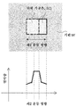
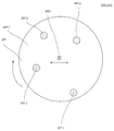
또한, 도 21a는, 일 실시 형태에 따른 부분 연마 장치(1000)를 사용한 연마 제어의 일례를 설명하는 개략도이다. 도 21a는, 기판 Wf의 상측 방향에서 본 개략도이며, 다른 부분 Wf-2에 비하여 막 두께가 두꺼운 일부분 Wf-1이 랜덤하게 형성되어 있는 예를 나타내고 있다. 또한, 도 21a에 있어서, 연마 패드(502)는, 대략 직사각형의 단위 가공흔(503)을 구비하도록 한다. 단위 가공흔(503)의 크기는, 연마 패드(502)와 기판 Wf의 접촉 면적에 상당한다. 도 21a에 도시한 바와 같이, 기판 Wf의 처리면에 있어서, 다른 부분 Wf-2에 비하여 막 두께가 두꺼운 일부분 Wf-1이 랜덤하게 형성되어 있다고 하자. 이 경우, 제어 장치(900)는, 스테이지(400)의 구동 기구에 의해 기판 Wf에 각도 회전 운동을 시킴으로써 기판 Wf의 막 두께가 두꺼운 일부분 Wf-1의 연마량을 다른 부분 Wf-2의 연마량보다 크게 할 수 있다. 예를 들어, 제어 장치(900)는, 기판 Wf의 막 두께가 두꺼운 일부분 Wf-1의 위치를 기판 Wf의 노치, 오리엔테이션 플랫, 또는 레이저 마커를 기준으로 하여 파악하고, 본 위치가 연마 헤드(500)의 요동 범위에 위치하도록, 스테이지(400)의 구동 기구에 의해 기판 Wf에 각도 회전 운동을 시킬 수 있다. 구체적으로는, 도 1, 3에 도시한 부분 연마 장치(1000)는, 기판 Wf의 노치, 오리엔테이션 플랫 및 레이저 마커 중 적어도 하나를 검지하는 검출부(408)를 구비하고, 검출된 노치, 오리엔테이션 플랫, 또는 레이저 마커 및 상태 검출부(420)에 의해 검출된 기판 Wf의 표면 상태의 분포로부터 산출된 연마 위치에, 연마 헤드(500)를 반경 방향으로, 또한 스테이지(400)의 기판 Wf를 임의의 소정 각도만큼 회전시킨다. 또한, 제어 장치(900)는, Wf-2의 영역이 원하는 막 두께인 경우에는, Wf-1만을 연마하면 된다. 또한, Wf-1 및 Wf-2의 양자를 연마하여, 원하는 막 두께로 할 경우, 기판 Wf의 막 두께가 두꺼운 일부분 Wf-1이 연마 헤드(500)의 요동 범위에 위치하고 있는 동안, 연마 헤드(500)의 회전수가 다른 부분 Wf-2와 비교해서 커지게 되도록, 연마 헤드(500)를 제어할 수 있다. 또한, 제어 장치(900)는, 기판 Wf의 막 두께가 두꺼운 일부분 Wf-1이 연마 헤드(500)의 요동 범위에 위치하고 있는 동안, 연마 패드(502)의 가압력이 다른 부분 Wf-2와 비교해서 커지게 되도록, 연마 헤드(500)를 제어할 수 있다. 또한, 제어 장치(900)는, 기판 Wf의 막 두께가 두꺼운 일부분 Wf-1이 연마 헤드(500)의 요동 범위에 위치하고 있는 동안의 연마 시간[연마 패드(502)의 체류 시간]이 다른 부분 Wf-2와 비교해서 커지게 되도록, 보유 지지 아암(600)의 요동 속도를 제어할 수 있다. 또한, 제어 장치(900)는, 연마 패드(502)가 기판 Wf의 막 두께가 두꺼운 일부분 Wf-1의 위가 되는 위치에서, 스테이지(400)를 정지시킨 상태에서 연마 헤드(500)를 회전시킴으로써, 기판 Wf의 막 두께가 두꺼운 일부분 Wf-1만을 연마하도록 제어할 수 있다. 이에 의해, 부분 연마 장치(1000)는 제어 장치(900)를 사용하여 연마 처리면을 편평하게 연마할 수 있다.21A is a schematic view for explaining an example of polishing control using the
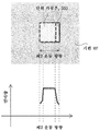
도 21b는, 부분 연마 장치(1000)를 사용한 연마 제어의 일례를 설명하는 개략도이다. 도 21b는, 기판 Wf의 상측 방향에서 본 개략도이며, 다른 부분 Wf-2에 비하여 막 두께가 두꺼운 일부분 Wf-1이 동심원 형상으로 형성되어 있는 예를 나타내고 있다. 또한, 도 21b에 있어서, 연마 패드(502)는, 대략 직사각형의 단위 가공흔(503)을 구비하도록 한다. 단위 가공흔(503)의 크기는, 연마 패드(502)와 기판 Wf의 접촉 면적에 상당한다. 도 21b에 도시한 바와 같이, 웨이퍼 Wf의 처리면에 있어서, 다른 부분 Wf-2에 비하여 막 두께가 두꺼운 일부분 Wf-1이 동심원 형상으로 형성되어 있다고 하자. 이 경우, 제어 장치(900)는, 스테이지(400)를 회전시킴과 함께, 보유 지지 아암(600)을 기판 Wf의 반경 방향으로 이동시킴으로써 연마를 행한다. 또한, Wf-2의 영역이 원하는 막 두께인 경우에는, 기판 Wf의 Wf-1의 영역만을 연마한다. 또한, Wf-1, Wf-2의 양자를 연마하여, 원하는 막 두께로 하는 경우, 연마 헤드(500)의 회전수가 Wf-1에 있어서, Wf-2보다도 커지게 되도록 제어할 수 있다. 또한, 제어 장치(900)는, Wf-1에 있어서, 연마 패드(502)의 가압력이 Wf-2보다도 커지게 되도록, 연마 헤드(500)를 제어할 수 있다. 또한, 제어 장치(900)는, Wf-1에 있어서의 연마 시간[연마 패드(502)의 체류 시간]이 Wf-2보다도 커지게 되도록, 보유 지지 아암(600)의 요동 속도를 제어할 수 있다. 이에 의해, 제어 장치(900)는, 웨이퍼 Wf의 연마 처리면을 편평하게 연마할 수 있다.21B is a schematic view for explaining an example of polishing control using the
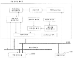
도 22a는, 일 실시 형태에 따른, 기판 Wf의 막 두께나 요철·높이에 관련된 정보를 처리하기 위한 제어 회로의 예를 나타낸다. 우선 처음에, 부분 연마용 제어부는, HMI(Human Machine Interface)로 설정된 연마 처리 레시피와 파라미터를 결합하고, 기본적인 부분 연마 처리 레시피를 결정한다. 이때, 부분 연마 처리 레시피와 파라미터는 HOST로부터 부분 연마 장치(1000)에 다운로드된 것을 사용해도 된다. 다음에 레시피 서버는 기본적인 부분 연마 처리 레시피와 프로세스 Job의 연마 처리 정보를 결합하고, 처리하는 기판 Wf마다의 기본적인 부분 연마 처리 레시피를 생성한다. 부분 연마 레시피 서버는 처리하는 기판 Wf마다의 부분 연마 처리 레시피와 부분 연마용 데이터베이스 내에 저장되어 있는 기판 표면 형상 데이터와, 또한 유사 기판에 관한 과거의 부분 연마 후의 기판 표면 형상 등의 데이터나 사전에 취득한 연마 조건의 각 파라미터에 대한 연마 속도 데이터를 결합하고, 기판마다의 부분 연마 처리 레시피를 생성한다. 이때, 부분 연마용 데이터베이스에 저장되어 있는 기판 표면 형상 데이터는 부분 연마 장치(1000) 내에서 측정된 해당 기판 Wf의 데이터를 사용해도 되고, 미리 HOST로부터 부분 연마 장치(1000)에 다운로드된 데이터를 사용해도 된다. 부분 연마 레시피 서버는 그 부분 연마 처리 레시피를 레시피 서버 경유, 혹은 직접 부분 연마 장치(1000)에 송신한다. 부분 연마 장치(1000)는 수취한 부분 연마 처리 레시피를 따라 기판 Wf를 부분 연마한다.Fig. 22A shows an example of a control circuit for processing information relating to the film thickness, ruggedness, and height of the substrate Wf according to one embodiment. First, the partial polishing control unit combines the polishing process recipe set with the HMI (Human Machine Interface) and the parameters, and determines the basic partial polishing process recipe. At this time, the partial polishing process recipe and the parameter may be downloaded from the HOST to the
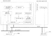
도 22b는, 도 22a에서 도시한 부분 연마용 제어부로부터 기판 표면의 상태 검출부를 분할했을 때의 회로도를 나타낸다. 대량의 데이터를 취급하는 기판의 표면 상태 검출용 제어부를 부분 연마용 제어부와 분리함으로써 부분 연마용 제어부의 데이터 처리의 부하가 저감하고, 프로세스 Job의 크리에이트 시간이나 부분 연마 처리 레시피의 생성에 요하는 처리 시간을 삭감하는 것을 기대할 수 있어, 부분 연마 모듈 전체의 스루풋 향상시킬 수 있다.22B shows a circuit diagram when the state detecting section on the substrate surface is divided from the partial polishing control section shown in Fig. 22A. Fig. By separating the control section for detecting the surface state of the substrate handling a large amount of data from the partial polishing control section, the load of the data processing of the partial polishing control section is reduced and the processing required for the creation time of the process job and the partial polishing process recipe Time can be expected to be reduced, and the throughput of the entire partial polishing module can be improved.
도 3은, 일 실시 형태에 따른 부분 연마 장치(1000)의 구성을 나타내는 개략도이다. 도 3에 도시된 부분 연마 장치(1000)는, 도 1에 도시된 부분 연마 장치(1000)는, 연마 패드(502), 가로 구동 기구(620), 세정 기구(200), 컨디셔닝부(800), 및 제2 컨디셔너(850)의 배치가 상이하다. 도 1의 실시 형태에 있어서는, 연마 패드(502)의 제1 운동 방향은 x방향으로 되도록 배치되어 있지만, 도 3에 도시된 실시 형태에 있어서는, 연마 패드(502)의 제1 운동 방향은 y방향으로 되도록 배치되어 있다. 또한, 도 1의 실시 형태에 있어서는, 가로 구동 기구(620)는, 보유 지지 아암(600)을 y방향으로 이동시키도록 구성되어 있지만, 도 3의 실시 형태에 있어서는, 가로 구동 기구(620)는 보유 지지 아암(600)을 x방향으로 이동시키도록 구성되어 있다. 도 1의 실시 형태에 있어서, 제2 컨디셔너(850)는, 연마 패드(502)로부터 x방향으로 이격되어 배치되어 있지만, 도 3의 실시 형태에 있어서는, 제2 컨디셔너(850)는, 연마 패드(502)로부터 y방향으로 이격되어 배치되고, 컨디셔닝 부재(852)를 y방향으로 이동 가능하도록 구성되어 있다. 전술한 바와 같이, 도 1의 실시 형태에 있어서는, 연마 패드(502)가 기판 Wf를 연마하기 위해서 운동하는 제1 운동 방향은 x방향이며, 제1 운동 방향으로 수직이며 또한 기판의 표면에 평행한 제2 운동 방향은 y방향이다. 한편, 도 3의 실시 형태에 있어서는, 연마 패드(502)가 기판 Wf를 연마하기 위해서 운동하는 제1 운동 방향은 y방향이며, 제1 운동 방향으로 수직이며 또한 기판의 표면에 평행한 제2 운동 방향은 x방향이다. 도 3의 부분 연마 장치(1000)의 그 밖의 구성은, 도 1에 도시된 부분 연마 장치(1000)와 마찬가지로 할 수 있으므로 설명을 생략한다.3 is a schematic view showing a configuration of the
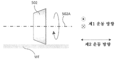
도 4는, 도 1 및 도 3에 도시된 부분 연마 장치(1000)에 이용할 수 있는 연마 패드(502)의 일례를 나타내는 도면이다. 단, 도 4는, 도시의 명료화를 위해 연마 패드(502)와 기판 Wf만을 간략적으로 나타내고 있으며, 다른 구성은 생략하여 도시하고 있다. 도 4의 연마 패드(502)는 원판 형상이다. 도 4의 원판 형상의 연마 패드(502)의 중심축은 기판 Wf의 표면에 평행하다. 도 4의 연마 패드(502)의 회전축(502A)은 중심축과 일치하고 있다. 전술한 바와 같이, 연마 패드(502)는, 회전 운동에 의해 기판 Wf에 대하여 제1 운동 방향으로 운동하고, 또한, 제1 운동 방향으로 수직이며 또한 기판 Wf의 표면에 평행한 제2 운동 방향으로 이동 가능하게 구성된다.Fig. 4 is a view showing an example of a
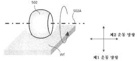
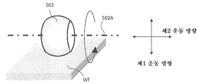
도 5는, 도 1 및 도 3에 도시된 부분 연마 장치(1000)에 이용할 수 있는 연마 패드(502)의 일례를 나타내는 도면이다. 단, 도 5는, 도시의 명료화를 위해서 연마 패드(502)와 기판 Wf만을 간략적으로 나타내고 있으며, 다른 구성은 생략하여 도시하고 있다. 도 5의 연마 패드(502)는 원기둥 형상이다. 또는, 원기둥 형상의 베이스 기판 Wf와의 접촉면에 연마 패드를 배치한 것을 채용해도 된다. 또한, 연마 패드의 재질은 시판 중인 CMP 패드에 사용되는 것이어도 된다. 도 5의 원기둥 형상의 연마 패드(502)의 중심축은 기판 Wf의 표면에 평행하다. 도 5의 연마 패드(502)의 회전축(502A)은 중심축과 일치하고 있다. 전술한 바와 같이, 연마 패드(502)는, 회전 운동에 의해 기판 Wf에 대해서 제1 운동 방향으로 운동하고, 또한, 제1 운동 방향으로 수직이며 또한 기판 Wf의 표면에 평행한 제2 운동 방향으로 이동 가능하게 구성된다.5 is a view showing an example of a
도 6은, 도 1 및 도 3에 도시된 부분 연마 장치(1000)에 이용할 수 있는 연마 패드(502)의 일례를 나타내는 도면이다. 단, 도 6은, 도시의 명료화를 위해 연마 패드(502)와 기판 Wf만을 간략적으로 나타내고 있으며, 다른 구성은 생략하여 도시하고 있다. 도 6의 연마 패드(502)는 단면 형상이 대략 사각형의 평판 형상이다. 또는, 평판 형상의 베이스 기판 Wf와의 접촉면(측면)에 연마 패드를 배치한 것을 채용해도 된다. 또한, 연마 패드의 재질은 시판 중인 CMP 패드에 사용되는 것이어도 된다. 도 6의 평판 형상의 연마 패드(502)는, 평판 형상의 하나의 면이 기판 Wf에 평행하게 접촉하도록 연마 헤드(500)에 보유 지지된다. 도 6의 연마 패드(502)는, 기판 Wf에 접촉한 상태에서, 기판 Wf에 평행한 방향(제1 운동 방향)으로 왕복 운동하도록 구성된다. 또한, 도 6의 연마 패드(502)는, 제1 운동 방향으로 수직이며 또한 기판 Wf의 표면에 평행한 제2 운동 방향으로 이동 가능하게 구성된다.Fig. 6 is a view showing an example of a
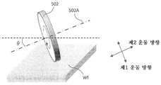
도 7은, 도 1 및 도 3에 도시된 부분 연마 장치(1000)에 이용할 수 있는 연마 패드(502)의 일례를 나타내는 도면이다. 단, 도 7은, 도시의 명료화를 위해서 연마 패드(502)와 기판 Wf만을 간략적으로 나타내고 있으며, 다른 구성은 생략하여 도시하고 있다. 도 7의 연마 패드(502)는 원판 형상이다. 또는, 원판 형상의 베이스 기판 Wf와의 접촉면(측면)에 연마 패드를 배치한 것을 채용해도 된다. 또한, 연마 패드의 재질은 시판 중인 CMP 패드에 사용되는 것이어도 된다. 도 7의 원판 형상의 연마 패드(502)의 중심축은 기판 Wf의 표면에 대해서 경사져 있다. 도 7에 도시된 바와 같이, 연마 패드(502)의 중심축은, 기판 Wf의 표면에 평행한 직선에 대해서 각도 θ만큼 경사져 있다. 또한, 도 7의 연마 패드(502)의 회전축(502A)은 중심축과 일치하고 있다. 도 7의 연마 패드(502)는, 중심축이 기판 Wf에 대해서 경사져 있으므로, 원판 형상의 연마 패드(502)의 측면 일부만이 기판 Wf에 접촉하게 되고, 연마 패드(502)와 기판 Wf의 접촉 면적이, 예를 들어 도 4에 도시된 경우보다도 작아지게 되어, 단위 가공흔(503)을 보다 작게 할 수 있다. 도 7에 도시된 연마 패드(502)는, 회전 운동에 의해 기판 Wf에 대해서 제1 운동 방향으로 운동하고, 또한, 제1 운동 방향으로 수직이며 또한 기판 Wf의 표면에 평행한 제2 운동 방향으로 이동 가능하게 구성된다.7 is a view showing an example of a
도 8은, 도 1 및 도 3에 도시된 부분 연마 장치(1000)에 이용할 수 있는 연마 패드(502)의 일례를 나타내는 도면이다. 단, 도 8은, 도시의 명료화를 위해서 연마 패드(502)와 기판 Wf만을 간략적으로 나타내고 있으며, 다른 구성은 생략하여 도시하고 있다. 도 8의 연마 패드(502)는 단면 형상이 대략 사각형의 평판 형상이다. 또는, 평판 형상의 베이스 기판 Wf와의 접촉면에 연마 패드를 배치한 것을 채용해도 된다. 또한, 연마 패드의 재질은 시판 중인 CMP 패드에 사용되는 것이어도 된다. 도 8의 평판 형상의 연마 패드(502)는, 평판 형상의 1개의 변이 기판 Wf에 접촉하도록 연마 헤드(500)에 보유 지지된다. 바꾸어 말하면, 평판 형상의 연마 패드(502)의 기판 Wf쪽을 향하는 면이, 도 8에 도시된 바와 같이, 기판 Wf의 표면에 대해서 각도 θ만큼 경사져 있다. 도 8의 연마 패드(502)는, 기판 Wf에 접촉한 상태에서, 기판 Wf에 평행한 방향(제1 운동 방향)으로 왕복 운동하게 구성된다. 이러한 제1 운동 방향은, 예를 들어 기판 Wf에 접촉하고 있는 연마 패드(502)의 변의 방향이다. 또한, 도 8의 연마 패드(502)는, 제1 운동 방향으로 수직이며 또한 기판 Wf의 표면에 평행한 제2 운동 방향으로 이동 가능하게 구성된다.8 is a view showing an example of a
도 9는, 도 1 및 도 3에 도시된 부분 연마 장치(1000)에 이용할 수 있는 연마 패드(502)의 일례를 나타내는 도면이다. 단, 도 9는, 도시의 명료화를 위해서 연마 패드(502)와 기판 Wf만을 간략적으로 나타내고 있으며, 다른 구성은 생략하여 도시하고 있다. 도 9의 연마 패드(502)는 원추 형상이다. 또는, 원추 형상의 베이스 기판 Wf와의 접촉면에 연마 패드를 배치한 것을 채용해도 된다. 또한, 연마 패드의 재질은 시판 중인 CMP 패드에 사용되는 것이어도 된다. 도 9의 원추 형상의 연마 패드(502)의 중심축은 기판 Wf의 표면에 평행하다. 도 9의 연마 패드(502)의 회전축(502A)은 중심축과 일치하고 있다. 전술한 바와 같이, 연마 패드(502)는, 회전 운동에 의해 기판 Wf에 대해서 제1 운동 방향(도 9에 있어서는 지면에 수직인 방향)으로 운동하고, 또한, 제1 운동 방향으로 수직이며 또한 기판 Wf의 표면에 평행한 제2 운동 방향으로 이동 가능하게 구성된다.9 is a view showing an example of a
도 10은, 도 1 및 도 3에 도시된 부분 연마 장치(1000)에 이용할 수 있는 연마 패드(502)의 일례를 나타내는 도면이다. 단, 도 10은, 도시의 명료화를 위해서 연마 패드(502)와 기판 Wf만을 간략적으로 나타내고 있으며, 다른 구성은 생략하여 도시하고 있다. 도 10의 연마 패드(502)는 원뿔대 형상이다. 도 10의 원뿔대 형상의 연마 패드(502)의 중심축은 기판 Wf의 표면에 평행하다. 또는, 원뿔대 형상의 베이스 기판 Wf와의 접촉면에 연마 패드를 배치한 것을 채용해도 된다. 또한, 연마 패드의 재질은 시판 중인 CMP 패드에 사용되는 것이어도 된다. 도 10의 연마 패드(502)의 회전축(502A)은 중심축과 일치하고 있다. 전술한 바와 같이, 연마 패드(502)는, 회전 운동에 의해 기판 Wf에 대하여 제1 운동 방향(도 10에 있어서는 지면에 수직인 방향)으로 운동하고, 또한, 제1 운동 방향으로 수직이며 또한 기판 Wf의 표면에 평행한 제2 운동 방향으로 이동 가능하게 구성된다.10 is a view showing an example of a
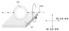
도 11은, 도 1 및 도 3에 도시된 부분 연마 장치(1000)에 이용할 수 있는 연마 패드(502)의 일례를 나타내는 도면이다. 단, 도 11은, 도시의 명료화를 위해서 연마 패드(502)와 기판 Wf만을 간략적으로 나타내고 있으며, 다른 구성은 생략하여 도시하고 있다. 도 11의 연마 패드(502)는 구형상이다. 또는, 구형상의 베이스 기판 Wf와의 접촉면에 연마 패드를 배치한 것을 채용해도 된다. 또한, 연마 패드의 재질은 시판 중인 CMP 패드에 사용되는 것이어도 된다. 도 11의 구형상의 연마 패드(502)의 회전축(502A)은 기판 Wf의 표면에 평행하다. 전술한 바와 같이, 연마 패드(502)는, 회전 운동에 의해 기판 Wf에 대해서 제1 운동 방향으로 운동하고, 또한, 제1 운동 방향으로 수직이며 또한 기판 Wf의 표면에 평행한 제2 운동 방향으로 이동 가능하게 구성된다.11 is a view showing an example of a
도 12는, 도 1 및 도 3에 도시된 부분 연마 장치(1000)에 이용할 수 있는 연마 패드(502)의 일례를 나타내는 도면이다. 단, 도 12는, 도시의 명료화를 위해서 연마 패드(502)와 기판 Wf만을 간략적으로 나타내고 있으며, 다른 구성은 생략하여 도시하고 있다. 도 12의 연마 패드(502)는 구형상의 일부를 구비하는 형상이다. 또는, 구형상의 일부를 구비하는 형상의 베이스를 사용하고, 이러한 베이스의 기판 Wf와의 접촉면에 연마 패드를 배치한 것을 채용해도 된다. 또한, 연마 패드의 재질은 시판 중인 CMP 패드에 사용되는 것이어도 된다. 도 12의 연마 패드(502)의 회전축(502A)은 기판 Wf의 표면에 평행하다. 전술한 바와 같이, 연마 패드(502)는, 회전 운동에 의해 기판 Wf에 대해서 제1 운동 방향으로 운동하고, 또한, 제1 운동 방향으로 수직이며 또한 기판 Wf의 표면에 평행한 제2 운동 방향으로 이동 가능하도록 구성된다.12 is a view showing an example of a
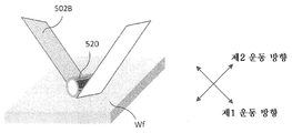
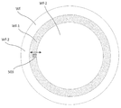
도 13은, 도 1 및 도 3에 도시된 부분 연마 장치(1000)의 연마 패드(502) 대신 이용할 수 있는 연마 부재의 일례인 연마 벨트 부재(502B)를 나타내는 도면이다. 단, 도 13은, 도시의 명료화를 위해서 연마 벨트 부재(502B), 연마 벨트 부재(502B)를 기판 Wf에 접촉시키기 위한 연마 벨트 지지 부재(520), 및 기판 Wf만을 간략적으로 나타내고 있으며, 다른 구성은 생략하여 도시하고 있다. 연마 벨트 부재(502B)는, 예를 들어 시판 중인 CMP 패드와 같은 재질로 이루어진다. 도 13의 연마 벨트 부재(502B)는 길이 방향으로 이동 가능하다. 즉 제1 운동 방향은 연마 벨트 부재(502B)의 길이 방향이다. 도 13의 연마 벨트 부재(502B)는, 길이 방향의 일방향으로만 이동 가능해도 되며, 또한 양방향으로 이동 가능하게 해도 된다. 또한, 도 13의 연마 벨트 부재(502B)는, 연마 벨트 지지 부재(520)와 함께 길이 방향으로 수직이며 또한 기판 Wf의 표면에 평행한 제2 운동 방향으로 이동 가능하게 구성된다.13 is a view showing an
도 14는, 도 1 및 도 3에 도시된 부분 연마 장치(1000)에 이용할 수 있는 연마 패드(502)의 일례를 나타내는 도면이다. 단, 도 14는, 도시의 명료화를 위해서 연마 패드(502)와 기판 Wf만을 간략적으로 나타내고 있으며, 다른 구성은 생략하여 도시하고 있다. 도 14의 연마 패드(502)는, 도 4에 도시된 연마 패드(502)와 마찬가지로 원판 형상이다. 도 14의 원판 형상의 연마 패드(502)의 중심축은 기판 Wf의 표면에 평행하다. 도 14의 연마 패드(502)의 회전축(502A)은 중심축과 일치하고 있다. 전술한 바와 같이, 연마 패드(502)는, 회전 운동에 의해 기판 Wf에 대해서 제1 운동 방향으로 운동할 수 있다. 도 4에 도시된 실시 형태와는 달리, 도 14의 연마 패드(502)는, 연마 패드(502)와 기판 Wf의 접촉점을 중심으로 회전 운동 및/또는 각도 회전 운동이 가능하게 구성된다.14 is a view showing an example of a
도 15는, 도 1 및 도 3에 도시된 부분 연마 장치(1000)에 이용할 수 있는 연마 패드(502)의 일례를 나타내는 도면이다. 단, 도 15는, 도시의 명료화를 위해서 연마 패드(502)와 기판 Wf만을 간략적으로 나타내고 있으며, 다른 구성은 생략하여 도시하고 있다. 도 15의 연마 패드(502)는 원판 형상이다. 도 15의 연마 패드(502)의 회전축(502A)는 기판 Wf의 표면에 평행하다. 그러나, 도 15의 원판 형상의 연마 패드(502)의 중심축은 기판 Wf의 표면에 대해서 경사져 있다. 연마 패드(502)의 회전축(502A)과 연마 패드(502)의 중심축이 소정의 각도 θ만큼 경사져 있다고도 할 수 있다. 도 15의 연마 패드(502)에 있어서는, 회전축(502A)과 중심축이 경사져 있으므로, 연마 패드(502)를 회전시키면, 연마 패드(502)와 기판 Wf의 접촉 영역이 이동하게 되므로, 결과적으로 도 4에 도시된 연마 패드(502)를 회전시키면서, 연마 패드(502)를 제2 운동 방향[도 4의 실시 형태에서는 회전축(502A)의 방향]으로 왕복 운동시키는 데도 유사한 효과를 발휘할 수 있다.15 is a view showing an example of a
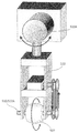
도 16은, 도 1 및 도 3에 도시된 부분 연마 장치(1000)에 이용할 수 있는 연마 패드(502)의 일례를 나타내는 도면이다. 단, 도 16은, 도시의 명료화를 위해서 연마 패드(502)와 기판 Wf만을 간략적으로 나타내고 있으며, 다른 구성은 생략하여 도시하고 있다. 도 16의 연마 패드(502)는, 도 12에 도시된 연마 패드(502)와 마찬가지로 구형상의 일부를 구비하는 형상이다. 도 16의 연마 패드(502)의 회전축(502A)은 기판 Wf의 표면에 평행하다. 전술한 바와 같이, 연마 패드(502)는, 회전 운동에 의해 기판 Wf에 대해서 제1 운동 방향(도 16에 있어서는 지면에 수직인 방향)으로 운동하고, 또한, 제1 운동 방향으로 수직이며 또한 기판 Wf의 표면에 평행한 제2 운동 방향으로 이동 가능하게 구성된다. 단, 도 16의 실시 형태에 있어서는, 도 12의 실시 형태와는 달리, 제2 운동 방향으로의 이동은, 연마 패드(502)로부터 벗어나서 상방에 위치하는 지지점(522A)을 중심으로 진자 운동함으로써 실현된다. 도 17은, 도 16에 도시된 연마 패드(502)에 진자 운동을 부여하는 구동 기구를 나타내는 도면이다. 도 17에 도시된 바와 같이, 연마 패드(502)는, 회전 샤프트(510)에 고정되어 있다. 회전 샤프트(510)는, 모터 및 벨트에 의해 회전 구동된다. 도 17에 도시된 바와 같이, 연마 패드(502)는, 회전 샤프트(510)와 함께 진자 지지 부재(522)에 보유 지지되어 있다. 진자 지지 부재(522)는, 지지점(522A)을 중심으로 모터에 의해 회전 운동을 부여할 수 있다. 진자 지지 부재(522)의 회전 중심축은, 연마 패드(502)의 회전 중심축에 직교하도록 구성되어 있다. 그로 인해, 진자 운동에 의해, 연마 패드(502)에 제1 운동 방향으로 수직이며 또한 기판 Wf의 표면에 평행한 제2 운동 방향으로 운동을 부여할 수 있다.16 is a view showing an example of a
전술한 실시 형태에 따른 부분 연마 장치(1000)는, 기판 Wf를 연마하기 위해서 연마 패드(502)를 제1 구동 기구에 의해 제1 운동 방향으로 운동시킬 수 있다. 제1 운동 방향은, 연마 패드(502)와 기판 Wf의 접촉 영역에서 연마 패드(502)가 이동하는 방향이다. 예를 들어, 연마 패드(502)가 원판 형상이며, 회전 운동을 하는 경우, 연마 패드(502)의 제1 운동 방향은, 연마 패드(502)와 기판 Wf의 접촉 영역에서의 연마 패드(502)의 접선 방향이 된다. 또한, 전술한 실시 형태에 따른 부분 연마 장치(1000)는, 가로 구동 기구(620)에 의해 제1 운동 방향으로 수직이며 또한 기판 Wf에 평행한 방향으로 성분을 갖는 제2 운동 방향으로 연마 패드(502)를 운동시킬 수 있다. 전술한 바와 같이, 기판 Wf의 연마 중에 연마 패드(502)를 제2 운동 방향으로 운동시킴으로써, 기판 Wf의 가공흔 형상을 보다 균일하게 할 수 있다. 연마 중에 있어서의 연마 패드(502)의 제2 운동 방향으로의 이동량은 임의이지만, 다양한 관점에서 제2 운동 방향으로의 이동량을 결정할 수 있다.The
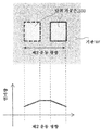
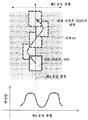
도 18a 내지 도 18e는, 연마 패드(502)의 제2 운동 방향의 이동량을 설명하기 위한 도면이다. 도 18a는, 도 4에 도시된 원판 형상의 연마 패드(502)와 마찬가지이며, 회전축(502A) 및 중심축은 기판 Wf의 표면에 평행이며 또한 일치하고 있다. 도 18a에 도시된 원판 형상의 연마 패드(502)를 회전시켜 제1 운동 방향으로 운동시키고, 또한, 제1 운동 방향으로 수직인 제2 운동 방향으로 연마 패드(502)를 왕복 이동시키는 경우를 생각한다. 도 18b는, 도 18a에 도시된 연마 패드(502)를 제2 운동 방향으로 왕복 운동시킨 경우의 연마량을 나타내고 있다. 도 18b의 상방은, 기판 Wf의 상측 방향에서 본 개략도이며, 기판 Wf에 형성되는 단위 가공흔(503)을 개략적으로 나타내고 있다. 단위 가공흔(503)의 크기는, 연마 패드(502)와 기판 Wf의 접촉 면적에 상당한다. 도 18a에 도시된 원판 형상의 연마 패드(502)의 경우, 단위 가공흔(503)은 대략 정사각형 또는 대략 직사각형이 된다. 또한, 도 11 등에 도시된 구형상의 연마 패드(502)의 경우에는, 단위 가공흔(503)은 원형이 된다. 도 18b 아래의 그래프는, 도 18a에 도시된 연마 패드(502)를 회전시키면서, 제2 운동 방향으로 일정한 속도로 왕복 운동시킨 경우의 연마량을 나타내는 그래프이다. 도 18b에 있어서는, 제2 운동 방향의 이동량은, 단위 가공흔(503)의 제2 운동 방향의 폭[원판 형상의 연마 패드(502)의 두께]보다도 크다. 연마 패드(502)를 일정 속도로 회전시키고, 일정 속도로 제2 운동 방향으로 왕복시키는 경우, 기판 Wf 위의 각 점의 연마량은, 연마 패드(502)의 체류 시간에 비례하므로 도시한 바와 같이 된다. 도 18c는 도 18b와 마찬가지의 도면이지만, 연마 패드(502)의 제2 운동 방향의 이동량이 단위 가공흔(503)의 제2 운동 방향의 폭과 동등하다. 도 18d는, 도 18b와 마찬가지의 도면이지만, 연마 패드(502)의 제2 운동 방향의 이동량이 단위 가공흔(503)의 제2 운동 방향의 폭보다도 작다. 도 18e는, 도 18b와 마찬가지의 도면이지만, 연마 패드(502)의 제2 운동 방향의 이동량이, 단위 가공흔(503)의 제2 운동 방향의 폭보다도 도 18d의 경우보다도 더 작다. 전술한 바와 같이, 연마 패드(502)의 제2 운동 방향으로의 이동량은 필요한 연마량에 따라서 적절히 설정하면 된다. 연마 패드(502)의 제2 운동 방향으로의 이동 거리가 크면, 제2 운동 방향의 가공흔 형상이 커지므로, 국소 영역의 부분 연마에는 적합하지 않은 경우도 있다. 한편, 연마 패드(502)의 제2 운동 방향으로의 이동량이 작으면, 제2 운동 방향에 있어서의 연마량의 변동을 저감하는 효과가 작아지거나, 제2 운동 방향의 연마량 분포가 에지 부분에서 너무 급준하거나 하는 경우도 있다. 일례로서, 제2 운동 방향에 있어서의 연마량의 변동을 저감하면서, 가공흔 형상을 작게 하기 위해서, 제2 운동 방향에 있어서의 연마 패드(502)의 이동량은 기판 Wf와 연마 패드(502)의 접촉 영역의 제2 운동 방향의 길이 이하로 할 수 있다.18A to 18E are views for explaining the movement amount of the
본 개시에 의한 부분 연마 장치(1000)의 몇 가지의 실시 형태에 있어서는, 전술한 바와 같이 기판 Wf를 보유 지지하는 스테이지(400)를 회전 운동 및/또는 직선 운동시키기 위한 이동 기구를 구비할 수 있다. 그로 인해, 기판 Wf를 연마 중에, 기판 Wf를 이동시킬 수 있다. 이러한 기판 Wf의 이동 방향을 여기에서는 제4 운동 방향이라 한다. 이때, 스테이지(400)에 의한 기판 Wf의 제4 운동 방향의 이동 속도는, 연마 패드(502)의 제2 운동 방향에 있어서의 운동 속도보다도 작아지도록 설정하는 것이 바람직하다. 이것은, 연마 패드(502)의 제2 운동 방향의 운동은, 연마량의 변동을 저감시켜 균일한 가공흔 형상으로 하기 위해서이다. 도 19a 내지 도 19c는, 연마 패드(502)의 제2 운동 방향으로의 이동과, 기판 Wf의 제4 운동 방향으로의 이동이 연마량에 미치는 영향을 설명하는 도면이다. 도 19a는, 도 4에 도시된 원판 형상의 연마 패드(502)와 마찬가지이며, 회전축(502A) 및 중심축은 기판 Wf의 표면에 평행하며 또한 일치하고 있다. 도 19a에 도시된 원판 형상의 연마 패드(502)를 회전시켜서 제1 운동 방향으로 운동시키고, 또한, 제1 운동 방향으로 수직인 제2 운동 방향으로 연마 패드(502)를 왕복 이동시키는 경우를 생각한다. 여기서, 기판 Wf는, 스테이지(400)에 의해 제1 운동 방향과 동일한 방향인 제4 운동 방향으로 이동시킬 수 있는 경우를 예로서 설명한다. 도 19b, 도 19c의 상방의 도면은, 이러한 상황에 있어서, 연마 패드(502)가 기판 Wf에 형성하는 단위 가공흔(503)의 기판 Wf 위의 궤적을 나타내는 도면이다. 도 19b, 도 19c의 하방의 도는, 제4 운동 방향에 있어서의 기판 Wf의 연마량을 나타내는 그래프이다. 도 19b는, 기판 Wf의 제4 운동 방향의 속도가, 연마 패드(502)의 제2 운동 방향의 속도보다도 빠른 경우를 나타내고 있다. 도 19b에 도시된 바와 같이, 제4 운동 방향의 속도가 빠른 경우, 제2 운동 방향으로 연마 패드(502)가 왕복 운동하고 있을 때, 기판 Wf가 제4 운동 방향으로 빠르게 이동해버려서, 제4 운동 방향의 연마량의 불균일이 발생한다. 또한, 제4 운동 방향의 속도가 빠른 경우, 제2 운동 방향의 운동에 의해 연마량의 변동을 저감시키는 효과가 그다지 얻어지지 않는다. 도 19c는, 기판 Wf의 제4 운동 방향의 속도가, 연마 패드(502)의 제2 운동 방향의 속도보다도 느린 경우를 나타내고 있다. 도 19c에 도시된 바와 같이, 제4 운동 방향의 속도가 느릴 경우, 제2 운동 방향의 왕복 운동에 의해 기판 Wf 위의 각 점을 연마 패드(502)가 복수 회 통과하게 되므로, 제4 운동 방향의 연마량의 불균일이 작아지게 된다. 도 19a 내지 도 19c에 있어서는, 제4 운동 방향으로의 운동은, 스테이지(400)에 의해 기판 Wf를 이동시킴으로써 설명했지만, 제4 운동 방향으로의 운동은, 연마 패드(502)를 기판 Wf에 대해서 제2 운동 방향과 상이한 방향으로 이동시키도록 해도 된다. 즉, 여기에서 말하는 제4 운동 방향은, 전술한 제2 운동 방향과 상이한 방향으로 연마 패드(502)와 기판 Wf를 상대적으로 이동시키는 것이면 된다.In some embodiments of the
또한, 도 19a 내지 도 19c에 있어서는, 제4 운동 방향으로의 운동은 제2 운동 방향과 상이한 방향의 경우를 설명하였지만, 예를 들어 제4 운동 방향이 제2 운동 방향과 일치하고 있어도 된다. 예를 들어, 도 1에서 도시한 부분 연마 장치(1000)에서는 연마 패드(502)의 제1 운동 방향은 기판 Wf 원주에 대해서 수직이 되도록 배치되어 있다. 이 상태에서 기판 Wf 위에 원주 위에 분포하는 피연마 영역을 연마하는 경우, 스테이지(400)를 회전 혹은 각도 회전시키도록 된다. 이 경우 스테이지(400)의 제4 운동 방향은 연마 패드(502)의 제1 운동 방향이 대해서 수직이 되고, 이것은 제2 운동 방향과 일치한다. 이 경우는, 제4 운동 방향으로 운동을 발생시키는 운동 기구가, 제2 운동 방향으로 운동을 발생시키는 운동 기구의 작용을 겸해도 된다. 또한 도 1에 도시한 부분 연마 장치(1000)에서는, 연마 패드(502)의 제1 운동 방향은 기판 Wf 원주 방향에 대해서 수직이 되도록 배치되어 있지만, 제2 운동 방향에 상당하는 수직 방향의 운동 방향을 갖고 있으면 되며, 예를 들어 45°와 같은 일정 각도로 기판 Wf 원주 방향, 즉 제4 운동 방향으로 기울여 배치하고 있어도 된다.19A to 19C, the movement in the fourth movement direction is different from the second movement direction. However, for example, the fourth movement direction may coincide with the second movement direction. For example, in the
도 23은, 일 실시 형태에 따른, 부분 연마 장치(1000)를 탑재한 기판 처리 시스템(1100)을 나타내는 개략도이다. 도 23에 도시된 바와 같이, 기판 처리 시스템(1100)은, 부분 연마 장치(1000), 대직경 연마 장치(1200), 세정 장치(1300), 건조 장치(1400), 제어 장치(900), 및 반송 기구(1500)를 구비한다. 기판 처리 시스템(1100)의 부분 연마 장치(1000)는, 전술한 임의의 특징을 구비하는 부분 연마 장치(1000)로 할 수 있다. 대직경 연마 장치(1200)는, 연마 대상으로 되는 기판 Wf보다도 큰 면적을 구비하는 연마 패드를 사용하여 기판을 연마하는 연마 장치이다. 대직경 연마 장치(1200)로서는, 공지된 CMP 장치를 이용할 수 있다. 또한, 세정 장치(1300), 건조 장치(1400), 및 반송 기구(1500)에 대해서도, 임의의 공지된 것을 채용할 수 있다. 제어 장치(900)는, 전술한 부분 연마 장치(1000)뿐만 아니라, 기판 처리 시스템(1100)의 전체의 동작을 제어하도록 할 수 있다. 도 23에 도시된 실시 형태에 있어서는, 부분 연마 장치(1000)와 대직경 연마 장치(1200)는, 1개의 기판 처리 시스템(1100)에 내장되어 있다. 그로 인해, 부분 연마 장치(1000)에 의한 부분 연마, 대직경 연마 장치(1200)에 의한 기판 Wf의 전체 연마 및 상태 검출부에 의한 기판 Wf의 표면 상태의 검출을 조합함으로써, 다양한 연마 처리를 행할 수 있다. 또한, 부분 연마 장치(1000)에 의한 부분 연마에서는, 기판 Wf의 표면 전체가 아니라 일부만을 연마하도록 할 수 있거나, 또는, 부분 연마 장치(1000)에 있어서 기판 Wf의 표면 전체의 연마 처리를 행하는 중에서, 기판 Wf의 표면의 일부에 있어서 연마 조건을 변경하여 연마를 행하도록 할 수 있다.23 is a schematic diagram showing a
여기서, 본 기판 처리 시스템(1100)에서의 부분 연마 방법에 대하여 설명한다. 우선, 처음에 연마 대상물인 기판 Wf의 표면의 상태를 검출한다. 표면 상태는, 기판 Wf 위에 형성되는 막의 막 두께나 표면의 요철에 관한 정보(위치, 사이즈, 높이 등) 등이며, 전술한 상태 검출부(420)에 의해 검출된다. 이어서, 검출된 기판 Wf의 표면 상태에 따라서 연마 레시피를 작성한다. 여기서, 연마 레시피는 복수의 처리 스텝으로 구성되어 있으며, 각 스텝에 있어서의 파라미터로서는, 예를 들어 부분 연마 장치(1000)에 대해서는, 처리 시간, 연마 패드(502)의 기판 Wf나 드레스 스테이지(810)에 배치된 드레서(820)에 대한 접촉 압력 혹은 하중, 연마 패드(502)나 기판 Wf의 회전수, 연마 헤드(500)의 이동 패턴 및 이동 속도, 연마 패드 처리액의 선택 및 유량, 드레스 스테이지(810)의 회전수, 연마 종점의 검출 조건이 있다. 또한, 부분 연마에 있어서는, 전술한 상태 검출부(420)에 의해 취득한 기판 Wf 면 내의 막 두께나 요철에 관한 정보를 기초로 기판 Wf면 내에서의 연마 헤드(500)의 동작을 결정할 필요가 있다. 예를 들어 기판 Wf의 면 내의 각 피연마 영역에서의 연마 헤드(500)의 체류 시간에 대해서는, 본 결정에 대한 파라미터로서는, 예를 들어 원하는 막 두께나 요철 상태에 상당하는 타깃 값이나 상기의 연마 조건에 있어서의 연마 속도를 들 수 있다. 여기서 연마 속도에 대해서는, 연마 조건에 따라 상이하기 때문에, 데이터베이스로서 제어 장치(900) 내에 저장되고, 연마 조건을 설정하면 자동으로 산출되어도 된다. 여기서 기초가 되는 각 파라미터에 대한 연마 속도는 사전에 취득해 두고, 데이터베이스로서 저장해 두어도 된다. 이들 파라미터와 취득한 기판 Wf 면 내의 막 두께나 요철에 관한 정보로부터 기판 Wf면 내에 있어서의 연마 헤드(500)의 체류 시간이 산출 가능하다. 또한, 후술하는 바와 같이, 전 측정, 부분 연마, 전체 연마, 세정의 루트는 기판 Wf의 상태나 사용하는 처리액에 따라 상이하기 때문에, 이들 구성 요소의 반송 루트의 설정을 행해도 된다. 또한, 기판 Wf 면 내의 막 두께나 요철 데이터의 취득 조건의 설정도 행해도 된다. 또한, 후술하는 바와 같이 처리 후의 Wf 상태가 허용 레벨에 도달하지 않는 경우, 재연마를 실시할 필요가 있지만, 그 경우의 처리 조건(재연마의 반복 횟수 등)을 설정해도 된다. 그 후, 작성된 연마 레시피에 따라서, 부분 연마 및 전체 연마를 행한다. 또한, 본 예 및 이하에서 설명하는 다른 예에 있어서, 기판 Wf의 세정은 임의의 타이밍에 행할 수 있다. 예를 들어, 부분 연마와 전체 연마에 있어서 사용하는 처리액이 상이하고, 부분 연마의 처리액 전체 연마에 대한 콘타미네이션을 무시할 수 없는 경우에 있어서는, 이것을 방지할 목적으로, 부분 연마 및 전체 연마의 각각의 연마 처리의 후에 기판 Wf의 세정을 행해도 된다. 또한, 반대로 처리액이 동일한 경우나 처리액의 콘타미네이션을 무시할 수 있는 처리액의 경우, 부분 연마 및 전체 연마의 양쪽을 행한 후에 기판 Wf의 세정을 행해도 된다.Here, a partial polishing method in the
이상, 몇 가지 예에 기초하여 본 발명의 실시 형태에 대하여 설명해 왔지만, 상기한 발명의 실시 형태는, 본 발명의 이해를 용이하게 하기 위한 것이고, 본 발명을 한정하는 것은 아니다. 본 발명은, 그 취지를 일탈하지 않고, 변경, 개량될 수 있음과 함께, 본 발명에는, 그 균등물이 포함되는 것은 물론이다. 또한, 전술한 과제 중 적어도 일부를 해결할 수 있는 범위, 또는 효과의 적어도 일부를 발휘하는 범위에 있어서, 청구범위 및 명세서에 기재된 각 구성 요소의 임의의 조합 또는, 생략이 가능하다.The embodiments of the present invention have been described above based on several examples. However, the embodiments of the present invention are for facilitating understanding of the present invention and are not intended to limit the present invention. It is needless to say that the present invention can be modified and improved without departing from the spirit and scope of the present invention. It is also possible to omit any combination or omission of each component described in the claims and the specification in the range in which at least part of the above-mentioned problems can be solved or at least part of the effect is exerted.
200: 세정 기구
208: 린스 노즐
400: 스테이지
410: 회전 구동 기구
420: 상태 검출부
500: 연마 헤드
502: 연마 패드
503: 단위 가공흔
600: 보유 지지 아암
602: 수직 구동 기구
620: 가로 구동 기구
700: 처리액 공급 계통
800: 컨디셔닝부
850: 제2 컨디셔너
852: 컨디셔닝 부재
900: 제어 장치
1000: 부분 연마 장치
502B: 연마 벨트 부재
Wf: 기판200: cleaning device
208: Rinse nozzle
400: stage
410: Rotary driving mechanism
420:
500: Polishing head
502: polishing pad
503: Unit processing
600: Retaining arm
602: Vertical drive mechanism
620:
700: Process liquid supply system
800: conditioning unit
850: Second conditioner
852: Conditioning member
900: Control device
1000: Partial polishing apparatus
502B: abrasive belt member
Wf: substrate
Claims (31)
기판에 접촉하는 가공면이 기판보다도 작은 연마 부재와,
상기 연마 부재를 기판에 가압시키기 위한 가압 기구와,
상기 연마 부재에, 기판의 표면에 평행한 제1 운동 방향으로 운동을 부여하기 위한 제1 구동 기구와,
상기 제1 운동 방향으로 수직이고 또한 기판의 표면에 평행한 방향으로 성분을 갖는 제2 운동 방향으로, 상기 연마 부재에 운동을 부여하기 위한 제2 구동 기구와,
연마 장치의 동작을 제어하기 위한 제어 장치를 갖고,
기판을 연마하고 있을 때, 상기 연마 부재는, 기판에 접촉하고 있는 영역 상의 임의의 점이 동일한 상기 제1 운동 방향으로 운동하도록 구성되고,
상기 제어 장치는, 상기 연마 부재를 사용하여 기판을 국소적으로 연마하도록, 상기 제1 구동 기구 및 제2 구동 기구의 동작을 제어하도록 구성되는, 연마 장치.A polishing apparatus for locally polishing a substrate,
An abrasive member having a machined surface contacting the substrate smaller than the substrate,
A pressing mechanism for pressing the abrasive member against the substrate,
A first driving mechanism for imparting motion to the polishing member in a first direction of motion parallel to the surface of the substrate,
A second drive mechanism for imparting motion to the abrasive member in a second direction of movement having a component perpendicular to the first direction of movement and parallel to the surface of the substrate,
And a control device for controlling the operation of the polishing apparatus,
When the substrate is being polished, the abrasive member is configured to move in the first direction of movement in which any point on the area in contact with the substrate is the same,
Wherein the control device is configured to control operations of the first driving mechanism and the second driving mechanism to locally polish the substrate using the polishing member.
상기 제어 장치는, 상기 제1 운동 방향의 운동 속도를 기판의 연마 중에 변경하도록 구성되는, 연마 장치.The method according to claim 1,
Wherein the control device is configured to change a moving speed of the first moving direction during polishing of the substrate.
상기 제2 운동 방향의 이동량은, 기판과 상기 연마 부재의 접촉 영역 중 제2 운동 방향의 성분의 길이 이하인, 연마 장치.3. The method according to claim 1 or 2,
Wherein the amount of movement in the second direction of movement is equal to or less than the length of a component of the contact area of the substrate and the abrasive member in the second direction of movement.
상기 연마 부재를 기판의 반경 방향으로 이동시키기 위한 제3 구동 기구를 갖는, 연마 장치.4. The method according to any one of claims 1 to 3,
And a third driving mechanism for moving the polishing member in the radial direction of the substrate.
기판을 보유 지지하기 위한 스테이지와,
상기 스테이지를 운동시키기 위한 제4 구동 기구를 갖는, 연마 장치.5. The method according to any one of claims 1 to 4,
A stage for holding a substrate;
And a fourth drive mechanism for moving the stage.
상기 제2 구동 기구에 의해 발생하는 상기 제2 운동 방향에 있어서의 연마 부재의 운동 속도는, 상기 제3 구동 기구에 의한 연마 부재의 운동 속도, 및 상기 제4 구동 기구에 의한 상기 연마 부재에 대한 상기 스테이지의 운동 속도보다도 큰, 연마 장치.6. The method according to claim 5,
Wherein the moving speed of the polishing member in the second moving direction generated by the second driving mechanism is set so that the moving speed of the polishing member by the third driving mechanism and the moving speed of the polishing member by the fourth driving mechanism Wherein the speed of movement of the stage is greater than the speed of movement of the stage.
상기 스테이지의 운동은, 회전 운동, 각도 회전 운동, 및 직선 운동 중 어느 하나인, 연마 장치.The method according to claim 6,
Wherein the motion of the stage is any one of a rotational motion, an angular rotational motion, and a linear motion.
상기 제어 장치는, 기판의 피연마 영역에서의 목표 연마량을 계산하는 연산부를 갖고, 상기 연산부에 의해 계산된 목표 연마량에 따라서, 연마 장치를 제어하도록 구성되는, 연마 장치.8. The method according to any one of claims 1 to 7,
Wherein the control device has an operation section for calculating a target polishing amount in a polishing area of the substrate and is configured to control the polishing device in accordance with the target polishing amount calculated by the calculation section.
상기 연마 부재를 컨디셔닝하기 위한 컨디셔닝 부재를 갖는, 연마 장치.9. The method according to any one of claims 1 to 8,
And a conditioning member for conditioning the polishing member.
상기 컨디셔닝 부재를 운동시키는 제5 구동 기구를 갖는, 연마 장치.10. The method of claim 9,
And a fifth drive mechanism for moving the conditioning member.
상기 컨디셔닝 부재는, 상기 스테이지의 밖에 배치되는, 연마 장치.10. The method according to claim 9,
Wherein the conditioning member is disposed outside the stage.
기판 위에 액체를 공급하기 위한 액체 공급 노즐을 갖는, 연마 장치.12. The method according to any one of claims 1 to 11,
And a liquid supply nozzle for supplying liquid onto the substrate.
상기 액체는, 연마제, 물 및 세정 약액 중 적어도 하나를 포함하는, 연마 장치.13. The method of claim 12,
Wherein the liquid comprises at least one of an abrasive, water, and cleaning liquid.
상기 제1 구동 기구는, 상기 연마 부재를 회전시키도록 구성되는, 연마 장치.14. The method according to any one of claims 1 to 13,
And the first driving mechanism is configured to rotate the polishing member.
상기 연마 부재는 원판 형상인, 연마 장치.15. The method of claim 14,
Wherein the polishing member has a disk shape.
원판 형상의 상기 연마 부재의 중심축이 기판의 표면에 평행하게 배치되는, 연마 장치.16. The method of claim 15,
And a central axis of the disk-like polishing member is disposed parallel to the surface of the substrate.
원판 형상의 상기 연마 부재의 중심축이 기판의 표면에 대해서 비평행하게 배치되는, 연마 장치.15. The method of claim 14,
And a center axis of the disk-shaped polishing member is arranged so as not to be opposed to the surface of the substrate.
상기 제1 구동 기구가 원판 형상의 상기 연마 부재를 회전시킬 때의 회전 중심축은, 원판 형상의 상기 연마 부재의 중심축으로부터 경사져 있는, 연마 장치.18. The method of claim 17,
Wherein the rotation center axis when the first driving mechanism rotates the disc-shaped polishing member is inclined from the central axis of the disc-like polishing member.
상기 연마 부재는 원기둥 형상인, 연마 장치.15. The method of claim 14,
Wherein the polishing member has a cylindrical shape.
원기둥 형상의 상기 연마 부재의 중심축이 기판의 표면에 평행하게 배치되는, 연마 장치.20. The method of claim 19,
And a central axis of the cylindrical polishing member is arranged parallel to the surface of the substrate.
상기 연마 부재는 구형상 또는 구형상의 일부를 구비하는 형상인, 연마 장치.15. The method of claim 14,
Wherein the polishing member has a shape having a spherical or spherical shape.
상기 제2 구동 기구는, 상기 연마 부재의 외측에 위치하는 점을 중심으로 상기 연마 부재를 진자 운동시키도록 구성되는, 연마 장치.22. The method of claim 21,
And the second driving mechanism is configured to cause the polishing member to pivot about a point located on the outer side of the polishing member.
상기 연마 부재는 평판 형상인, 연마 장치.14. The method according to any one of claims 1 to 13,
Wherein the polishing member has a flat plate shape.
평판 형상의 상기 연마 부재는, 기판에 접촉하는 표면이 기판의 표면에 대해서 경사지도록 배치되는, 연마 장치.24. The method of claim 23,
Wherein the abrasive member in the form of a flat plate is disposed so that a surface contacting the substrate is inclined with respect to the surface of the substrate.
상기 연마 부재는, 원추 형상 또는 원뿔대 형상이며,
상기 원추 형상 또는 상기 원뿔대 형상의 중심축은, 기판의 표면에 대해서 평행하게 배치되는, 연마 장치.15. The method of claim 14,
The polishing member may have a conical shape or a truncated conical shape,
And the center axis of the conical shape or the truncated conical shape is arranged parallel to the surface of the substrate.
상기 제2 구동 기구는, 상기 연마 부재를 기판 위에서 직선 운동 또는 회전 운동시키도록 구성되는, 연마 장치.26. The method according to any one of claims 14 to 25,
And the second driving mechanism is configured to linearly move or rotate the polishing member on the substrate.
상기 연마 부재는, 벨트 부재를 갖고,
상기 제1 구동 기구는 벨트를 길이 방향으로 이동시키고, 상기 제2 구동 기구는, 벨트를 폭 방향으로 이동시키도록 구성되는, 연마 장치.14. The method according to any one of claims 1 to 13,
Wherein the abrasive member has a belt member,
Wherein the first driving mechanism moves the belt in the longitudinal direction and the second driving mechanism is configured to move the belt in the width direction.
제1항 내지 제27항 중 어느 한 항에 기재된 연마 장치와,
상기 연마 장치에 의해 연마한 기판을 세정하기 위한 세정 장치와,
상기 세정 장치에 의해 세정한 기판을 건조시키기 위한 건조 장치와,
상기 연마 장치, 상기 세정 장치, 및 상기 건조 장치의 사이에 기판을 반송하기 위한 반송 장치를 갖는, 기판 처리 시스템.A substrate processing system comprising:
A polishing apparatus comprising: the polishing apparatus according to any one of claims 1 to 27;
A cleaning device for cleaning the substrate polished by the polishing device,
A drying device for drying the substrate cleaned by the cleaning device,
And a transporting device for transporting the substrate between the polishing device, the cleaning device, and the drying device.
기판에 접촉하는 가공면이 기판보다도 큰 연마 부재를 사용하여 기판을 연마하기 위한 대직경 연마 장치를 더 갖는, 기판 처리 시스템.29. The method of claim 28,
Further comprising a large-diameter polishing apparatus for polishing the substrate by using an abrasive member having a machining surface in contact with the substrate larger than the substrate.
기판의 처리 전 및/또는 처리 후에, 기판의 표면 상태를 검출하기 위한 상태 검출부를 갖는, 기판 처리 시스템.30. The method of claim 28 or 29,
And a state detecting section for detecting the surface state of the substrate before and / or after the processing of the substrate.
상기 상태 검출부는, 기판의 표면에 형성되어 있는 막의 막 두께, 기판의 표면 단차, 및 이들에 상당하는 신호 중 적어도 하나에 관하여, 기판의 표면 내의 분포를 검출하도록 구성되는, 기판 처리 시스템.31. The method of claim 30,
Wherein the state detecting section is configured to detect a distribution in a surface of the substrate with respect to at least one of a film thickness formed on a surface of the substrate, a surface step difference of the substrate, and a signal corresponding thereto.
Applications Claiming Priority (2)
| Application Number | Priority Date | Filing Date | Title |
|---|---|---|---|
| JP2017031243A JP2018134710A (en) | 2017-02-22 | 2017-02-22 | Polishing device and polishing method of substrate |
| JPJP-P-2017-031243 | 2017-02-22 |
Publications (1)
| Publication Number | Publication Date |
|---|---|
| KR20180097136A true KR20180097136A (en) | 2018-08-30 |
Family
ID=63166818
Family Applications (1)
| Application Number | Title | Priority Date | Filing Date |
|---|---|---|---|
| KR1020180019296A KR20180097136A (en) | 2017-02-22 | 2018-02-19 | Polishing apparatus and polishing method of substrate |
Country Status (6)
| Country | Link |
|---|---|
| US (1) | US20180236630A1 (en) |
| JP (1) | JP2018134710A (en) |
| KR (1) | KR20180097136A (en) |
| CN (1) | CN108453618A (en) |
| SG (1) | SG10201801373RA (en) |
| TW (1) | TW201900338A (en) |
Families Citing this family (11)
| Publication number | Priority date | Publication date | Assignee | Title |
|---|---|---|---|---|
| JP6884015B2 (en) * | 2017-03-22 | 2021-06-09 | 株式会社荏原製作所 | Substrate polishing equipment and polishing method |
| CN109227388A (en) * | 2018-09-19 | 2019-01-18 | 大连理工大学 | A kind of glass polishing machine disk conditioning system and its working method |
| JP7145084B2 (en) * | 2019-01-11 | 2022-09-30 | 株式会社荏原製作所 | SUBSTRATE PROCESSING APPARATUS AND METHOD FOR SPECIFYING REGION TO BE POLISHED IN SUBSTRATE PROCESSING APPARATUS |
| US11235454B2 (en) * | 2019-01-14 | 2022-02-01 | Dynabrade, Inc. | Spring loaded adjustable head |
| JP7317532B2 (en) * | 2019-03-19 | 2023-07-31 | キオクシア株式会社 | Polishing device and polishing method |
| TWI771668B (en) | 2019-04-18 | 2022-07-21 | 美商應用材料股份有限公司 | Temperature-based in-situ edge assymetry correction during cmp |
| JP7442314B2 (en) * | 2019-12-24 | 2024-03-04 | 東京エレクトロン株式会社 | Substrate processing equipment and substrate processing method |
| JP7341918B2 (en) * | 2020-02-06 | 2023-09-11 | 株式会社荏原製作所 | Substrate processing equipment and substrate processing method |
| JP2022033603A (en) * | 2020-08-17 | 2022-03-02 | キオクシア株式会社 | Polishing device and polishing method |
| CN114012605B (en) * | 2022-01-05 | 2022-05-17 | 杭州众硅电子科技有限公司 | Polishing pad trimming device |
| CN116460667B (en) * | 2022-12-30 | 2023-11-07 | 北京创思工贸有限公司 | Processing method of calcium fluoride optical part |
Citations (1)
| Publication number | Priority date | Publication date | Assignee | Title |
|---|---|---|---|---|
| US20150352686A1 (en) | 2012-02-14 | 2015-12-10 | Taiwan Semiconductor Manufacturing Co., Ltd. | Chemical mechanical polishing (cmp) platform for local profile control |
Family Cites Families (25)
| Publication number | Priority date | Publication date | Assignee | Title |
|---|---|---|---|---|
| US3943666A (en) * | 1974-07-31 | 1976-03-16 | Dysan Corporation | Method and apparatus for burnishing flexible recording material |
| US4347689A (en) * | 1980-10-20 | 1982-09-07 | Verbatim Corporation | Method for burnishing |
| JPS59173555U (en) * | 1984-01-17 | 1984-11-20 | 株式会社ノリタケカンパニーリミテド | Inclined flange used in grinding equipment with an inclined grinding wheel |
| US4958463A (en) * | 1988-06-06 | 1990-09-25 | United Technologies Corporation | Optical surface quality improving arrangement |
| JPH033765A (en) * | 1989-05-29 | 1991-01-09 | Sony Corp | Processing method for surface of rigid substrate |
| JPH04322964A (en) * | 1991-04-22 | 1992-11-12 | Amada Washino Co Ltd | Grinding control method |
| JPH074750B2 (en) * | 1992-12-03 | 1995-01-25 | 株式会社松田精機 | Planar polishing device using film polishing material |
| JP3020800B2 (en) * | 1994-05-16 | 2000-03-15 | 株式会社ノリタケカンパニーリミテド | Grinding equipment for scratch removal |
| JPH0811042A (en) * | 1994-06-30 | 1996-01-16 | Nippondenso Co Ltd | Surface grinding method |
| JPH0947947A (en) * | 1994-08-30 | 1997-02-18 | Seiko Seiki Co Ltd | Grinding device, and grinding method, and semiconductor device, and manufacture of semiconductor substrate |
| JPH08108360A (en) * | 1994-10-11 | 1996-04-30 | Fuji Photo Film Co Ltd | Polishing device of glass substrate |
| JPH10329015A (en) * | 1997-03-24 | 1998-12-15 | Canon Inc | Polishing device and polishing method |
| JPH11285978A (en) * | 1998-04-03 | 1999-10-19 | Ebara Corp | Grinding wheel holding structure and polishing device |
| JP3652163B2 (en) * | 1999-03-15 | 2005-05-25 | キヤノン株式会社 | Polishing method |
| JP2001353659A (en) * | 2000-06-16 | 2001-12-25 | Okamoto Machine Tool Works Ltd | Method for determining acceptability of polish of polished wafer |
| US6811680B2 (en) * | 2001-03-14 | 2004-11-02 | Applied Materials Inc. | Planarization of substrates using electrochemical mechanical polishing |
| JP2003282493A (en) * | 2001-08-14 | 2003-10-03 | Sony Corp | Polishing machine and polishing method |
| US6875086B2 (en) * | 2003-01-10 | 2005-04-05 | Intel Corporation | Surface planarization |
| CN1822905A (en) * | 2003-06-06 | 2006-08-23 | P.C.T.系统公司 | Method and apparatus to process substrates with megasonic energy |
| JP2005177925A (en) * | 2003-12-19 | 2005-07-07 | Olympus Corp | Polishing method |
| JP4406772B2 (en) * | 2005-04-01 | 2010-02-03 | 株式会社サンシン | Plate-shaped member surface flaw repair device |
| JP2009190109A (en) * | 2008-02-13 | 2009-08-27 | Lasertec Corp | Substrate holding device and substrate machining device |
| JP5369478B2 (en) * | 2008-04-11 | 2013-12-18 | 株式会社ニコン | Polishing equipment |
| US9393669B2 (en) * | 2011-10-21 | 2016-07-19 | Strasbaugh | Systems and methods of processing substrates |
| CN103231303B (en) * | 2013-05-15 | 2016-02-24 | 清华大学 | Chemical-mechanical polisher |
-
2017
- 2017-02-22 JP JP2017031243A patent/JP2018134710A/en active Pending
-
2018
- 2018-02-12 TW TW107104944A patent/TW201900338A/en unknown
- 2018-02-14 CN CN201810151773.8A patent/CN108453618A/en active Pending
- 2018-02-19 KR KR1020180019296A patent/KR20180097136A/en not_active Application Discontinuation
- 2018-02-20 SG SG10201801373RA patent/SG10201801373RA/en unknown
- 2018-02-20 US US15/900,140 patent/US20180236630A1/en not_active Abandoned
Patent Citations (1)
| Publication number | Priority date | Publication date | Assignee | Title |
|---|---|---|---|---|
| US20150352686A1 (en) | 2012-02-14 | 2015-12-10 | Taiwan Semiconductor Manufacturing Co., Ltd. | Chemical mechanical polishing (cmp) platform for local profile control |
Also Published As
| Publication number | Publication date |
|---|---|
| SG10201801373RA (en) | 2018-09-27 |
| US20180236630A1 (en) | 2018-08-23 |
| TW201900338A (en) | 2019-01-01 |
| CN108453618A (en) | 2018-08-28 |
| JP2018134710A (en) | 2018-08-30 |
Similar Documents
| Publication | Publication Date | Title |
|---|---|---|
| KR20180097136A (en) | Polishing apparatus and polishing method of substrate | |
| JP2018134710A5 (en) | ||
| CN107186612B (en) | Substrate polishing apparatus, substrate polishing method, and recording medium | |
| US7070479B2 (en) | Arrangement and method for conditioning a polishing pad | |
| JP6000643B2 (en) | Workpiece processing method, and optical element, mold, and semiconductor substrate processed by the processing method | |
| US11396082B2 (en) | Substrate holding device and substrate processing apparatus including the same | |
| KR102482181B1 (en) | Substrate polishing device and polishing method | |
| JP7015139B2 (en) | Grinding method and grinding equipment for workpieces | |
| JPH10315131A (en) | Polishing method of semiconductor wafer and device therefor | |
| CN110732943A (en) | Polishing apparatus and polishing method for polishing peripheral portion of substrate | |
| JP5654365B2 (en) | Grinding equipment | |
| JP6539467B2 (en) | Grinding machine | |
| JP2019024053A (en) | Substrate processing device and method for detecting notch formed in substrate | |
| JP6736728B2 (en) | Grinding machine | |
| KR20210100014A (en) | Substrate processing device and substrate processing method | |
| KR20010040249A (en) | Polishing apparatus and method for producing semiconductors using the apparatus | |
| JP2009248258A (en) | Method of dressing polishing pad | |
| TW202133996A (en) | Substrate processing apparatus and substrate processing method and substrate polishing method | |
| JP2021126739A (en) | Substrate processing method and substrate processing device | |
| JP2001239457A (en) | Polishing device | |
| JP2020131398A (en) | Condition check method for grinding wheel | |
| JP2013144359A (en) | Method of dressing polishing pad |
Legal Events
| Date | Code | Title | Description |
|---|---|---|---|
| A201 | Request for examination | ||
| E902 | Notification of reason for refusal | ||
| E601 | Decision to refuse application |