JP5410340B2 - Cushion support structure for saddle-ride type vehicles - Google Patents
Cushion support structure for saddle-ride type vehicles Download PDFInfo
- Publication number
- JP5410340B2 JP5410340B2 JP2010052744A JP2010052744A JP5410340B2 JP 5410340 B2 JP5410340 B2 JP 5410340B2 JP 2010052744 A JP2010052744 A JP 2010052744A JP 2010052744 A JP2010052744 A JP 2010052744A JP 5410340 B2 JP5410340 B2 JP 5410340B2
- Authority
- JP
- Japan
- Prior art keywords
- cushion
- cross member
- saddle
- cushion support
- notch
- Prior art date
- Legal status (The legal status is an assumption and is not a legal conclusion. Google has not performed a legal analysis and makes no representation as to the accuracy of the status listed.)
- Expired - Fee Related
Links
Images


Classifications
-
- B—PERFORMING OPERATIONS; TRANSPORTING
- B62—LAND VEHICLES FOR TRAVELLING OTHERWISE THAN ON RAILS
- B62K—CYCLES; CYCLE FRAMES; CYCLE STEERING DEVICES; RIDER-OPERATED TERMINAL CONTROLS SPECIALLY ADAPTED FOR CYCLES; CYCLE AXLE SUSPENSIONS; CYCLE SIDE-CARS, FORECARS, OR THE LIKE
- B62K25/00—Axle suspensions
- B62K25/04—Axle suspensions for mounting axles resiliently on cycle frame or fork
- B62K25/28—Axle suspensions for mounting axles resiliently on cycle frame or fork with pivoted chain-stay
- B62K25/286—Axle suspensions for mounting axles resiliently on cycle frame or fork with pivoted chain-stay the shock absorber being connected to the chain-stay via a linkage mechanism
-
- B—PERFORMING OPERATIONS; TRANSPORTING
- B62—LAND VEHICLES FOR TRAVELLING OTHERWISE THAN ON RAILS
- B62K—CYCLES; CYCLE FRAMES; CYCLE STEERING DEVICES; RIDER-OPERATED TERMINAL CONTROLS SPECIALLY ADAPTED FOR CYCLES; CYCLE AXLE SUSPENSIONS; CYCLE SIDE-CARS, FORECARS, OR THE LIKE
- B62K11/00—Motorcycles, engine-assisted cycles or motor scooters with one or two wheels
- B62K11/02—Frames
- B62K11/04—Frames characterised by the engine being between front and rear wheels
-
- B—PERFORMING OPERATIONS; TRANSPORTING
- B62—LAND VEHICLES FOR TRAVELLING OTHERWISE THAN ON RAILS
- B62K—CYCLES; CYCLE FRAMES; CYCLE STEERING DEVICES; RIDER-OPERATED TERMINAL CONTROLS SPECIALLY ADAPTED FOR CYCLES; CYCLE AXLE SUSPENSIONS; CYCLE SIDE-CARS, FORECARS, OR THE LIKE
- B62K25/00—Axle suspensions
- B62K25/04—Axle suspensions for mounting axles resiliently on cycle frame or fork
- B62K25/28—Axle suspensions for mounting axles resiliently on cycle frame or fork with pivoted chain-stay
- B62K25/283—Axle suspensions for mounting axles resiliently on cycle frame or fork with pivoted chain-stay for cycles without a pedal crank, e.g. motorcycles
Description
本発明は、鞍乗り型車両のクッション支持構造に関する。 The present invention relates to a cushion support structure for a saddle-ride type vehicle.
自動二輪車には、リヤクッションの下端をスイングアームに支持する構造が知られている。この種の自動二輪車では、左右一対のスイングアームを車幅方向に連結するクロスメンバを備え、このクロスメンバにリヤクッションを支持するリヤクッション支持部を設け、クロスメンバの壁厚を、リヤクッション支持部側を大とし、非支持部側を小としている(例えば、特許文献1参照)。 A structure in which a lower end of a rear cushion is supported by a swing arm is known for a motorcycle. This type of motorcycle includes a cross member that connects a pair of left and right swing arms in the vehicle width direction, and a rear cushion support portion that supports the rear cushion is provided on the cross member, and the wall thickness of the cross member is supported by the rear cushion. The part side is made large and the non-supporting part side is made small (for example, refer to Patent Document 1).
ところで、リヤクッションの下端をスイングアームに支持する構造では、リヤクッションからの入力荷重がクロスメンバに作用する。この際、クロスメンバのリヤクッション支持部には、その形状によって応力集中が発生し易い。
従来の構造では、クロスメンバの幅方向全域に渡って厚肉に形成するため、強度が向上し応力集中を許容し易い構成であるが、クロスメンバの重量が増加してしまう。
By the way, in the structure in which the lower end of the rear cushion is supported by the swing arm, an input load from the rear cushion acts on the cross member. At this time, stress concentration is likely to occur in the rear cushion support portion of the cross member due to its shape.
In the conventional structure, since the cross member is formed thick across the entire width direction, the strength is improved and stress concentration is easily allowed, but the weight of the cross member increases.
本発明は、上述した事情を鑑みてなされたものであり、リヤクッションの支持強度を確保しつつ軽量かつ耐久性の高い鞍乗り型車両のクッション支持構造を提供することを目的としている。 The present invention has been made in view of the above-described circumstances, and an object thereof is to provide a cushion support structure for a saddle-ride type vehicle that is lightweight and highly durable while ensuring the support strength of the rear cushion.
上述した課題を解決するため、本発明は、車体フレーム(2)と、車体フレーム(2)に揺動可能に軸支され、後輪(8)を回転自在に支持する左右一対のスイングアームと、左右一対のスイングアーム(7)を車幅方向に連結するクロスメンバ(7A)と、クロスメンバ(7A)と車体フレーム(2)とで支持されるリヤクッション(51)とを備える鞍乗り型車両のクッション支持構造において、前記クロスメンバ(7A)は方形断面に形成され、このクロスメンバ(7A)の角部(7K)を跨いで隣接する面に渡って固定される補強板部材(100)を備え、この補強板部材(100)は、前記リヤクッション(51)を支持するクッション支持部(47)が固定される固定板部(110)を有し、この固定板部(110)は、前記クロスメンバ(7A)の前記角部(7K)近傍で車幅方向の幅を滑らかに減少させる切り欠き部(112)を有することを特徴とする。
この構成によれば、補強板部材の固定板部が、クロスメンバの角部近傍で車幅方向の幅を滑らかに減少させる切り欠き部を有するので、角部近傍での応力集中を低減することができ、リヤクッションの支持強度を確保しつつ軽量かつ耐久性を向上させることができる。
In order to solve the above-described problems, the present invention includes a vehicle body frame (2), a pair of left and right swing arms that are pivotally supported by the vehicle body frame (2) and rotatably support a rear wheel (8). The saddle riding type includes a cross member (7A) for connecting the pair of left and right swing arms (7) in the vehicle width direction, and a rear cushion (51) supported by the cross member (7A) and the vehicle body frame (2). In the vehicle cushion support structure, the cross member (7A) is formed in a square cross section, and the reinforcing plate member (100) is fixed over the adjacent surface across the corner (7K) of the cross member (7A). The reinforcing plate member (100) includes a fixed plate portion (110) to which a cushion support portion (47) that supports the rear cushion (51) is fixed. The fixed plate portion (110) Said Characterized in that it has the corner portions of the Sumenba (7A) and (7K) notch smoothly reducing width in the vehicle width direction in the vicinity (112).
According to this configuration, the fixing plate portion of the reinforcing plate member has the notch portion that smoothly reduces the width in the vehicle width direction in the vicinity of the corner portion of the cross member, so that stress concentration in the vicinity of the corner portion is reduced. It is possible to improve the weight and durability while ensuring the support strength of the rear cushion.
上記構成において、前記クッション支持部(47)は、前記クロスメンバ(7A)の前後中間位置よりも前記角部(7K)側に、前記リヤクッション(51)を揺動自在に支持する軸支部(47B)を有するようにしてもよい。この構成によれば、クッションストロークを長く設定可能なレイアウトにしながら、このレイアウトで生じ易い「クッション荷重の応力集中」を低減することができる。従って、応力集中を低減でき、軸支部の配置自由度を向上させつつ、クロスメンバの軽量化を図ることができる。 In the above configuration, the cushion support portion (47) is a pivotal support portion that swingably supports the rear cushion (51) closer to the corner portion (7K) than the front-rear intermediate position of the cross member (7A). 47B). According to this configuration, a “cushion load stress concentration” that tends to occur in this layout can be reduced while a layout in which the cushion stroke can be set to be long can be achieved. Therefore, stress concentration can be reduced, and the weight of the cross member can be reduced while improving the degree of freedom of arrangement of the shaft support portion.
上記構成において、前記固定板部(110)は、前記軸支部(47B)と、前記クロスメンバ(7A)の車幅方向端部における前後中間位置(P2)とを結ぶ直線(LD)上に、車幅方向の最外端(P3)を有するようにしてもよい。この構成によれば、応力集中の低減に有利な位置に最大幅部を設定でき、応力集中を効率よく低減できる。 In the above configuration, the fixed plate portion (110) is on a straight line (LD) connecting the shaft support portion (47B) and the front-rear intermediate position (P2) at the vehicle width direction end portion of the cross member (7A). You may make it have the outermost end (P3) of a vehicle width direction. According to this configuration, the maximum width portion can be set at a position advantageous for reducing the stress concentration, and the stress concentration can be efficiently reduced.
また、上記構成において、前記固定板部(110)は、前記最外端(P3)から前記角部(7K)と反対側に行くに従って車幅方向の幅が連続的に減少するようにしてもよい。この構成によれば、クッション加重が大きく作用する領域では切り欠き部により応力集中を回避し、クッション加重が大きく作用しない領域では、軽量化を図ることができる。従って、補強板部材の機能性を損なわずに、補強板部材を効率よく軽量化することができる。 In the above configuration, the width of the fixed plate portion (110) in the vehicle width direction continuously decreases from the outermost end (P3) toward the opposite side of the corner portion (7K). Good. According to this configuration, stress concentration can be avoided by the notch portion in the region where the cushion load acts greatly, and the weight can be reduced in the region where the cushion load does not act greatly. Therefore, the weight of the reinforcing plate member can be efficiently reduced without impairing the functionality of the reinforcing plate member.
また、上記構成において、前記切り欠き部(112)は、円弧形状に形成されるようにしてもよい。この構成によれば、切り欠き部での局部的な応力集中を低減することができる。
また、上記構成において、前記切り欠き部(112)の切り欠き半径(R)は、前記クロスメンバ(7A)の前後長さの半分よりも小さくしてもよい。この構成によれば、リヤクッションから作用する最大応力値を低減でき、応力集中をさらに低減することができる。
In the above configuration, the notch (112) may be formed in an arc shape. According to this configuration, local stress concentration at the notch can be reduced.
In the above configuration, the notch radius (R) of the notch (11 2 ) may be smaller than half of the front-rear length of the cross member (7A). According to this configuration, the maximum stress value acting from the rear cushion can be reduced, and the stress concentration can be further reduced.
本発明は、補強板部材の固定板部が、クロスメンバの角部近傍で車幅方向の幅を滑らかに減少させる切り欠き部を有するので、角部近傍での応力集中を低減することができ、リヤクッションの支持強度を確保しつつ軽量かつ耐久性を向上させることができる。
また、クッション支持部は、クロスメンバの前後中間位置よりも角部側に、リヤクッションを揺動自在に支持する軸支部を有するようにすれば、応力集中を低減でき、軸支部の配置自由度を向上させつつ、クロスメンバの軽量化を図ることができる。
In the present invention, the fixing plate portion of the reinforcing plate member has a notch portion that smoothly reduces the width in the vehicle width direction in the vicinity of the corner portion of the cross member, so that stress concentration in the vicinity of the corner portion can be reduced. Further, it is possible to improve the light weight and durability while ensuring the support strength of the rear cushion.
In addition, if the cushion support part has a shaft support part that supports the rear cushion in a swingable manner on the corner side of the cross member between the front and rear intermediate positions, stress concentration can be reduced, and the degree of freedom of arrangement of the shaft support part is reduced. It is possible to reduce the weight of the cross member while improving the above.
また、固定板部は、軸支部と、クロスメンバの車幅方向端部における前後中間位置とを結ぶ直線上に、車幅方向の最外端を有するようにすれば、応力集中の低減に有利な位置に最大幅部を設定でき、応力集中を効率よく低減できる。
また、固定板部は、最外端から角部と反対側に行くに従って車幅方向の幅が連続的に減少するようにすれば、補強板部材の機能性を損なわずに、補強板部材を効率よく軽量化することができる。
Further, if the fixed plate portion has an outermost end in the vehicle width direction on a straight line connecting the shaft support portion and the front-rear intermediate position at the end portion in the vehicle width direction of the cross member, it is advantageous in reducing stress concentration. It is possible to set the maximum width part at a proper position and to reduce stress concentration efficiently.
In addition, if the width of the fixed plate portion in the vehicle width direction decreases continuously from the outermost end to the opposite side of the corner portion, the reinforcing plate member can be attached without impairing the functionality of the reinforcing plate member. It is possible to reduce the weight efficiently.
また、切り欠き部は、円弧形状に形成されるようにすれば、切り欠き部での局部的な応力集中を低減することができる。
また、切り欠き部の切り欠き半径は、クロスメンバの前後長さの半分よりも小さくすれば、リヤクッションから作用する最大応力値を低減でき、応力集中をさらに低減することができる。
Further, if the notch is formed in an arc shape, local stress concentration at the notch can be reduced.
Further, if the notch radius of the notch is smaller than half of the front / rear length of the cross member, the maximum stress value acting from the rear cushion can be reduced, and the stress concentration can be further reduced.
以下、図面を参照して本発明の一実施の形態について説明する。なお、説明中、前後左右及び上下といった方向の記載は、特に記載がなければ車体に対する方向と同一とする。
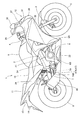
図1は、本発明の実施の形態に係る自動二輪車1の左側面図であり、図2は、自動二輪車1の後部を左側方から見た図である。
図1に示すように、自動二輪車1は、車体フレーム2と、車体フレーム2のヘッドパイプ20に操舵自在に支持される左右一対のフロントフォーク3と、これらフロントフォーク3と一体で車体前上部に配置された操舵用のハンドル4と、フロントフォーク3に回転自在に支持された前輪5と、車体の略中央で車体フレーム2に支持されたエンジン(内燃機関)6と、車体フレーム2に上下に揺動自在に支持されたスイングアーム(リヤフォークとも言う)7と、スイングアーム7の後端部に回転自在に支持された後輪8と、車体フレーム2の上部に配置された燃料タンク9と、この燃料タンク9の後方に配置された乗員用シート10、11と、車体を覆う車体カウル(カウリングとも言う)12とを備えている。
Hereinafter, an embodiment of the present invention will be described with reference to the drawings. In the description, descriptions of directions such as front and rear, right and left and up and down are the same as directions with respect to the vehicle body unless otherwise specified.
FIG. 1 is a left side view of a motorcycle 1 according to an embodiment of the present invention, and FIG. 2 is a view of a rear portion of the motorcycle 1 as viewed from the left side.
As shown in FIG. 1, a motorcycle 1 includes a
図2に示すように、車体フレーム2は、エンジン6を支持する左右一対のメインフレーム21と、運転者用の乗員用シート10と同乗者用の乗員用シート11とを支持するリヤフレーム22とを備えている。
メインフレーム21は、アルミニウム合金を鋳造したアルミフレームであり、ヘッドパイプ20から左右に分岐して後下方に延在する。このメインフレーム21の後端部には、下方に延びる左右一対のピボットプレート部24が設けられている。このメインフレーム21は、エンジン6、燃料タンク9及びこれら周辺の各種部品を支持する。
また、ピボットプレート部24における上下中間部には、スイングアーム7の前端部を回動自在に軸支するピボット軸13が貫通して支持される。このピボット軸13は、車幅方向に平行に配置され、スイングアーム7をピボット軸13を支点にして上下に揺動自在に支持する。
As shown in FIG. 2, the
The
A
リヤフレーム22は、アルミニウム合金等の金属材料からなる金属パイプで形成され、メインフレーム21の後部から上方に突出する左右一対のブラケット部21Aに連結され、後上方に延出する。この自動二輪車1では、このリヤフレーム22の後端部とブラケット部21Aとの間に左右一対の補強フレーム25が掛け渡され、リヤフレーム22の支持剛性を十分に確保している。このリヤフレーム22は、乗員用シート10,11を支持するとともに、乗員用シート11後方にて、後輪8の後上方を覆うリヤフェンダ14や後方灯火類15等を支持する(図1参照)。
The
図1に示すように、車体カウル12は、車体の略全体を覆うフルカウリングタイプに構成されており、車体前部を覆うフロントカウル31と、このフロントカウル31に連設されて車体左右を覆う左右一対のサイドカウル32と、車体下方を覆うロアカウル33と、車体後部を覆う左右一対のリヤカウル34とを備えている。
フロントカウル31は、ヘッドパイプ20及びメインフレーム21の前方に設けられる。このフロントカウル31には、ヘッドライト36、ウインドスクリーン37及び左右一対のバックミラー38が取り付けられる。
サイドカウル32は、フロントカウル31に連結され、車体フレーム2の前部左右やエンジン6の前部(シリンダ部6A)左右を覆うように下方に延在する。ロアカウル33は、サイドカウル32の下部に連結され、エンジン6のクランクケース6B下方を覆うように延在する。
As shown in FIG. 1, the
The
The
このエンジン6のシリンダ部6A後方には、図2に示すように、エンジン吸気系を構成するスロットルボディ41やエアクリーナ42が順に接続される。また、車体フレーム2の後下方かつ後輪8の側方(右側)には、マフラー43が配置され、このマフラー43の前端とエンジン6のシリンダ部6Aとの間に吸気管(不図示)が接続され、この吸気管とマフラー43とによってエンジン排気系が構成される。
この自動二輪車1では、リヤフレーム22とスイングアーム7との間に単一のリヤクッション51が介挿され、この単一のリヤクッション51で後輪8からスイングアーム7を経て車体フレーム2に伝わる衝撃を吸収するモノクッション構造が採られている。
As shown in FIG. 2, a
In the motorcycle 1, a single
図3は、リヤクッション51を周辺構成とともに車体後方から見た図である。なお、図中、符号L1は、リヤクッション51の軸線である。
図2及び図3に示すように、メインフレーム21の後部には、上方に突出する左右一対のブラケット部21Aが設けられ、この左右一対のブラケット部21Aの間に、車幅方向に延びるクロスメンバ21Bが架橋され、このクロスメンバ21Bの車幅方向中央に、リヤクッション51の上端部51Aを支持する上側クッション支持部45が設けられる。
この上側クッション支持部45は、クロスメンバ21Bの背面から後方向きに突出する左右一対のクッション支持ステー45Aを有し、これらステー45Aがリヤクッション51の上端部51Aを軸支する軸支部45Bを有し、この軸支部45Bの軸線LA(図3参照)を中心にしてリヤクッション51の上端部51Aを前後に揺動自在に支持する。
FIG. 3 is a view of the
As shown in FIGS. 2 and 3, a pair of left and
The upper
図2及び図3に示すように、左右一対のスイングアーム7間には、車幅方向に延びるクロスメンバ7Aが架橋され、このクロスメンバ7Aの上面の車幅方向中央に、下側クッション支持部47を構成する左右一対のクッション支持ステー47Aが設けられる。
左右一対のクッション支持ステー47Aは、上方に突出し、リヤクッション51の下端部51Bを軸支する軸支部47B(図2参照)を有し、この軸支部47Bの軸線LB(図3参照)を中心にしてリヤクッション51の下端部51Bを前後に揺動自在に支持する。
すなわち、この自動二輪車1では、リヤクッション51の上端部51Aが、上側クッション支持部45を介して車体フレーム2側のクロスメンバ21Bに支持され、リヤクッション51の下端部51Bが、下側クッション支持部47を介してスイングアーム7側のクロスメンバ7Aに支持される。このため、自動二輪車1が具備するクロスメンバ21B,7Aを利用して上下のクッション支持部45,47が設けられ、部品点数の低減やレイアウト効率の向上を図ることができる。
As shown in FIGS. 2 and 3, a
The pair of left and right cushion support stays 47A protrude upward and have a
That is, in the motorcycle 1, the
図2に示すように、下側クッション支持部47の軸支部47Bは、後輪8の前方であって、上側クッション支持部45の軸支部45Bよりも下方かつ後方に設けられる。このため、リヤクッション51は、上端部51Aを下端部51Bよりも前方に傾斜させた姿勢(後下がりで傾斜した姿勢)で懸架される。
また、本構成のクッション支持レイアウトは、下側クッション支持部47におけるリヤクッション51の軸支部47Bが、クロスメンバ7Aの背面寄りとされている。このレイアウトにすれば、リヤクッション51の軸支部47Bが、後方寄り(後輪8寄り)となるので、リヤクッションストロークを長く設定することができ、リヤクッション51の機能性を高めることが可能である。
一方、リヤクッション51と下側クッション支持部47との間に作用する荷重(以下、クッション荷重という)は、リヤクッション51の軸線L1方向に作用するため、上記クッション支持レイアウトでは、クロスメンバ7Aの後部にクッション荷重が集中し易くなり、クロスメンバ7Aの後部(クッション支持部分)の剛性を高める必要が生じる。
As shown in FIG. 2, the
Further, in the cushion support layout of this configuration, the
On the other hand, since a load acting between the
そこで、本自動二輪車1では、図3に示すように、スイングアーム7間のクロスメンバ7Aに補強板部材100を取り付け、この補強板部材100に下側クッション支持部47を取り付けることによって、クロスメンバ7Aの肉厚にすることなく、補強板部材100によってクロスメンバ7Aのクッション支持剛性を高めている。
まず、この補強板部材100の説明の前に、補強板部材100が取り付けられるスイングアーム7について説明する。
Therefore, in the motorcycle 1, as shown in FIG. 3, the reinforcing
First, before the description of the reinforcing
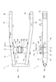
図4(A)はスイングアーム7の平面図を示し、図4(B)は側面図を示している。左右一対のスイングアーム7は、車幅方向内側から車幅方向外側に向かって後方に延びる前側アーム7Fと、前側アーム7Fの後端から前後方向に沿って後方へ延びる後側アーム7Rとを一体に備えている。
左右の前側アーム7Fの前端部、つまり、左右のスイングアーム7の前端部には、車幅方向に延びてピボット軸13(図2参照)が挿通されるパイプ部7Bが溶接により接合され、左右の前側アーム7Fの前後中間部には、車幅方向に延びるクロスメンバ7Aの両端部が溶接により接合される。これによって、左右のスイングアーム7は一体部品(スイングアームユニット)に形成される。
なお、図中、符号7Dは、後輪軸を通す貫通孔であり、符号7Gは、左右一対のスイングアーム7とクロスメンバ7Aとの連結部位の前後に溶接により接合され、スイングアーム7とクロスメンバ7Aとの連結強度を補強する補強部材である。この補強部材7Gについても、鋼板等の剛性を有する金属材料で形成されている。
FIG. 4A shows a plan view of the
A
In the figure,
図4(B)に示すように、クロスメンバ7Aは、前後方向に長い方形断面を有し、車幅方向に直線状に延びる角パイプ形状に形成されている。
クロスメンバ7Aに設けられる補強板部材100は、このクロスメンバ7Aの上面7Tと背面7Uとの間の角部7Kを跨ぐように配置され、その周縁が連続溶接されることによってクロスメンバ7Aの上面7Tと背面7Uとに接合される。
つまり、この補強板部材100は、クロスメンバ7Aの上面7Tに配置される固定板部110と、この固定板部110の後端部から屈曲して、クロスメンバ7Aの背面7Uに配置される屈曲板部120とを備えている。
この固定板部110の上面には、左右一対のクッション支持ステー47Aが溶接により接合され、この固定板部110がクッション支持ステー47Aからの荷重を直接受ける。この場合、クッション支持ステー47Aの軸支部47Bは、クロスメンバ7Aの前後中間位置よりも後方側(クロスメンバ7Aの角部7K寄り)に設けられるので(図4(B)参照)、上記したように、リヤクッションストロークを長く設定できる一方で、クロスメンバ7Aの後部にクッション荷重が集中し易くなっている。
As shown in FIG. 4B, the
The reinforcing
That is, the reinforcing
A pair of left and right cushion support stays 47A are joined to the upper surface of the fixed
ところで、この種の補強板部材をクロスメンバ7Aの全幅に渡って設ける従来構成では、強度を向上させ、応力集中を許容できるものの、補強板部材が大型化し、重量が増加してしまう。このため、発明者らは、補強板部材100をクロスメンバ7Aよりも幅狭とした条件で、補強板部材100の最適形状について検討した。
この検討では、発明者らは、補強板部材100のうち、軸支部74Bからの荷重を直接受ける固定板部110の形状に着目し、この軸支部47Bに想定されるクッション荷重(リヤクッション51からの入力荷重)を作用させた場合の応力分布のシミュレーションを行った。
なお、屈曲板部120の形状については、図3及び図4に示すように、補強板部材100の後縁から同幅で下方に延出し、クロスメンバ7Aの背面7Uの上下に渡って延在する方形板状(四角板状)としている。
By the way, in the conventional configuration in which this type of reinforcing plate member is provided over the entire width of the
In this examination, the inventors pay attention to the shape of the fixed
As shown in FIGS. 3 and 4, the shape of the
図5(A)は、補強板部材100のベースモデル(I)を示している。なお、図中、符号LCは、車幅方向中心線を示しており、補強板部材100は、車幅方向中心線LCに対して左右対称形状に形成されている。
発明者らは、本構成のクッション支持レイアウトの場合、クッション荷重が軸支部47Bから後下方に作用するので、軸支部47Bよりも前側にはクッション荷重が大きく作用しないと考え、図5(A)に示すように、軸支部47B(=軸線LB)近傍に位置する前後中間部110Mの幅を、車幅方向で最大幅Wに設定し、この前後中間部110Mよりも前側となる前側部110Fを、前方に行くほど幅が連続的に減少する上面視で台形形状に設定した。
また、発明者らは、前後中間部110Mよりも後側となる後側部110Rには、クッション荷重が大きく作用し、このクッション荷重は、後側部110Rの左右外縁に沿って形成される溶接部位を介してクロスメンバ7Aに作用することから、図5(A)に矢印で示すように、クロスメンバ7Aに伝達されるクッション荷重F1を異なる方向に分散させる分散効果を期待して、車幅方向内側(軸支部)に向かって凸の円弧形状に切り欠かれた切り欠き部112を左右外縁に設ける形状を設定した。
FIG. 5A shows a base model (I) of the reinforcing
In the case of the cushion support layout of the present configuration, the inventors think that the cushion load does not act greatly on the front side of the
Further, the inventors exert a large cushion load on the
図5(A)、図6(A)(B)、図7(A)〜(C)は、本発明の一実施形態を各々示しており、図8は、比較例を示している。また、図9は、軸支部に所定のクッション荷重を作用させた場合の最大応力値Sの比較結果を示している。なお、最大応力値Sは、いずれも前側部110Fの左右外縁部である切り欠き部112の領域で得られた。
図8に示す比較例は、ベースモデル(I)に対し、固定板部110の幅を一定にした「切り欠き部無しストレート形状(X)」であり、この固定板部110の幅は、ベースモデル(I)の最大幅Wと同じである。
図5(B)(C)は、ベースモデル(I)に対し、前側部110Fを変更した本発明の他の形態であり、図5(B)は、前側部110Fの幅を一定にした「前方ストレートタイプ(II)」であり、図5(C)は、前側部110Fの幅を前方に行くほど大きくした「前方拡大タイプ」(III)である。
図9に示すように、ベースモデル(I)、「前方ストレートタイプ(II)」及び「前方拡大タイプ」(III)は、いずれも比較例の「切り欠き部無しストレート形状(X)」と比較して最大応力値Sが低くなった。一方、(I)〜(III)間での比較では、最大応力値Sに殆ど違いがなかった。このことは前側部110Fをベースモデル(I)のように前方に行くほど幅が減少する形状(前方に行くほど車幅方向中心線LCに近づく直線形状)にしても、補強板部材100の機能性(最大応力値Sを下げる効果)は損なわれないことを示している。
このベースモデル(I)の前側部110Fは、(II)(III)の構成に比して、軽量であり、この点で、前側部110Fについては(I)が有利であると判断した。
FIG. 5 (A), the FIG. 6 (A) (B), FIG. 7 (A) ~ (C) shows each an embodiment of the present invention, FIG. 8 shows a comparative example. FIG. 9 shows a comparison result of the maximum stress value S when a predetermined cushion load is applied to the shaft support portion. The maximum stress value S was obtained in the region of the
The comparative example shown in FIG. 8 is a “straight shape without a notch (X)” in which the width of the fixed
FIGS. 5B and 5C show another embodiment of the present invention in which the
As shown in FIG. 9, the base model (I), the “front straight type (II)” and the “front enlarged type” (III) are all compared with the “straight shape without notches (X)” of the comparative example. As a result, the maximum stress value S was lowered. On the other hand, in the comparison between (I) to (III), there was almost no difference in the maximum stress value S. This is because the function of the reinforcing
The
図6(A)(B)は、ベースモデル(I)に対し、後側部110Rを変更した本発明の他の形態であり、図6(A)は、切り欠き部112の半径(切り欠き半径)Rを、ベースモデル(I)よりも小さくした「切り欠き半径小タイプ(IV)」であり、図6(B)は、切り欠き半径Rを、ベースモデル(I)よりも大きくした「切り欠き半径大タイプ(V)」である。
具体的には、ベースモデル(I)では、切り欠き半径Rを、クロスメンバの前後長さの半分の距離に対して約67%の長さとしたのに対し、「切り欠き半径小タイプ(IV)」では、切り欠き半径Rを、クロスメンバ7Aの前後長さの半分の距離に対して約57%の長さとし、「切り欠き半径大タイプ(V)」では、切り欠き半径Rを、クロスメンバ7Aの前後長さの半分の距離に対して約110%の長さとした。
図9に示すように、「切り欠き半径小タイプ(IV)」及び「切り欠き半径大タイプ(V)」は、いずれも比較例(X)と比較して最大応力値Sが低くなり、ベースモデル(I)との比較では、「切り欠き半径小タイプ(IV)」では、ベースモデル(I)よりも最大応力値Sが小さくなる側に改善し、「切り欠き半径大タイプ(V)」では、悪化した。
このことから、後側部110Rについては、応力低減の観点からは「切り欠き半径小タイプ(IV)」が有利であった。
更に、発明者らは、「切り欠き半径小タイプ(IV)」よりも切り欠き半径Rを小さくしたところ、(IV)よりも悪化することを確認した。これらの結果から、切り欠き半径Rについては、「切り欠き半径小タイプ(IV)」のものが、クッション荷重F1を異なる方向に分散させる分散効果を効率よく発揮させるものと推測し、応力集中の低減に最適であると判断した。
しかしながら、この「切り欠き半径小タイプ(IV)」は、ベースモデル(I)よりも重量が増大してしまう。このため、重量低減と応力低減とを両立する観点からは、ベースモデル(I)が有利であると判断した。
6A and 6B show another embodiment of the present invention in which the
Specifically, in the base model (I), the notch radius R is about 67% of the distance half of the front and rear length of the cross member, whereas the “notch radius small type (IV ) ”, The notch radius R is about 57% of the length of the half of the front and rear length of the
As shown in FIG. 9, both the “small notch radius type (IV)” and the “large notch radius type (V)” have a lower maximum stress value S than the comparative example (X), and the base In comparison with the model (I), the “small notch radius type (IV)” is improved so that the maximum stress value S becomes smaller than the base model (I), and the “large notch radius type (V)”. Then it got worse.
For this reason, the
Furthermore, the inventors have confirmed that when the notch radius R is made smaller than that of the “notch radius small type (IV)”, it is worse than that of (IV). From these results, for the notch radius R, it is estimated that the “notch radius small type (IV)” effectively exerts the dispersion effect of dispersing the cushion load F1 in different directions. Judged to be optimal for reduction.
However, this “notch radius small type (IV)” is heavier than the base model (I). For this reason, it was judged that the base model (I) is advantageous from the viewpoint of achieving both weight reduction and stress reduction.
図7(A)〜(C)は、ベースモデル(I)に対し、最大幅Wや最大幅Wの位置を変更した本発明の他の形態であり、図7(A)は、ベースモデル(I)よりも最大幅Wを大きくした「最大幅UPタイプ(VI)」であり、図7(B)は、ベースモデル(I)よりも最大幅Wを大きくし、かつ、最大幅Wの位置を前方寄りにした「最大幅UP&前方寄りタイプ(VII)」である。また、図7(C)は、ベースモデル(I)よりも最大幅Wを大きくし、かつ、最大幅Wの位置を後方寄りにした「最大幅UP&後方寄りタイプ(VIII)」である。
図9に示すように、「最大幅UPタイプ(VI)」及び「最大幅UP&前方寄りタイプ(VII)」は、いずれも比較例と比較して最大応力値Sが低くなり、ベースモデル(I)との比較では、「最大幅UPタイプ(VI)」では、ベースモデル(I)よりも最大応力値Sが小さくなる側に改善したが、「最大幅UP&前方寄りタイプ(VII)」及び「最大幅UP&後方寄りタイプ(VIII)」では、悪化した。
このことから、応力低減の観点からは「最大幅UPタイプ(VI)」が有利であった。
しかしながら、この「最大幅UPタイプ(VI)」についても、ベースモデル(I)よりも重量が増大してしまう。このため、重量低減と応力低減とを両立する観点からは、ベースモデル(I)が有利であると判断した。
FIGS. 7A to 7C show another embodiment of the present invention in which the position of the maximum width W and the maximum width W is changed with respect to the base model (I). FIG. “Maximum width UP type (VI)” in which the maximum width W is larger than I), and FIG. 7B shows the position where the maximum width W is larger than that of the base model (I) and the maximum width W is present. Is the “maximum width UP & forward type (VII)”. FIG. 7C shows the “maximum width UP & rearward type (VIII)” in which the maximum width W is larger than that of the base model (I) and the position of the maximum width W is closer to the rear.
As shown in FIG. 9, the “maximum width UP type (VI)” and the “maximum width UP & forward type (VII)” both have a lower maximum stress value S than the comparative example, and the base model (I ), The “maximum width UP type (VI)” has improved to the side where the maximum stress value S becomes smaller than that of the base model (I), but the “maximum width UP & forward type (VII)” and “ The maximum width UP & rearward type (VIII) "deteriorated.
From this point of view, the “maximum width UP type (VI)” was advantageous from the viewpoint of stress reduction.
However, the “maximum width UP type (VI)” also increases in weight compared to the base model (I). For this reason, it was judged that the base model (I) is advantageous from the viewpoint of achieving both weight reduction and stress reduction.
このように、上記いずれのバリエーション(I)〜(VIII)についても、比較例と比べれば応力低減を図ることができた。また、これらのバリエーション(I)〜(VIII)の中で比較すると、ベースモデル(I)が好適であることが判った。
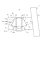
発明者らは、最大幅Wの位置を変更する等して更に検討を重ねた結果、図10に示すように、クッション支持ステー47Aがリヤクッション51下端を軸支する軸支部47Bの位置P1と、クロスメンバ7Aの車幅方向端部における前後中間位置P2とを結ぶ直線LD上に最外端P3を位置させると、最大応力値Sを低くできることが判った。
この検討結果から、発明者らは、上記直線LD上がクロスメンバ7Aのねじれ等の影響による応力集中を抑える有利な位置と推測し、この直線LD上に最外端Pを位置させる形状が有利であると判断した。
Thus, in any of the above variations (I) to (VIII), the stress could be reduced as compared with the comparative example. Moreover, when comparing among these variations (I) to (VIII), it was found that the base model (I) was suitable.
As a result of further investigations by changing the position of the maximum width W, etc., the inventors have found that the cushion support stay 47A and the position P1 of the
From this examination result, the inventors presume that the above-mentioned straight line LD is an advantageous position for suppressing stress concentration due to the influence of torsion or the like of the
以上を踏まえ、発明者らは、図10に示す形状が最適であると判断した。
すなわち、補強板部材100は、図10に示すように、クロスメンバ7Aの上面7Tに配置される固定板部110の最大幅部となる左右の最外端P3が、図10に示す直線LD上に位置し、前側部110Fが、最外端P3から前方かつ車幅方向内側に向かって斜めに切り欠かれた直線状の切り欠き部114を左右両側に有し、上面視で前方に行くほど幅狭となる台形形状に形成され、後側部110Rが、最外端Pから後方かつ車幅方向内側(軸支部47B)に向かって凸の円弧形状に切り欠かれた円弧状の切り欠き部112を左右両側に有し、上面視で後方に行くほど幅狭となる形状に形成される。
この構成にすることで、クッション荷重が作用した場合の最大応力値Sを低減でき、しかも、小型で軽量な補強板部材100を得ることができる。
Based on the above, the inventors have determined that the shape shown in FIG. 10 is optimal.
That is, as shown in FIG. 10, the reinforcing
With this configuration, it is possible to reduce the maximum stress value S when the cushion load is applied, and to obtain a small and lightweight reinforcing
図10に示すように、本構成では、補強板部材100の固定板部110が、クロスメンバ7Aの上面7Tと背面7Uとの境界である角部7K近傍で車幅方向の幅を滑らかに減少させる切り欠き部112を有するので、シミュレーションで得られたように、角部7K近傍での応力集中を低減することができる。また、この切り欠き部112によって、単純な直線形状の切り欠きにした場合よりも、補強板部材100の溶接長を長くすることができ、これによっても、補強板部材100とクロスメンバ7Aとの連結強度を高めることができる。
この構成によれば、クロスメンバ7Aの全幅に渡って補強板部材を設ける構成にしなくても、リヤクッション51の支持強度を確保することが可能である。これにより、リヤクッション51の支持強度を確保しつつ軽量かつ耐久性を向上させることが可能になる。
As shown in FIG. 10, in this configuration, the fixing
According to this configuration, the support strength of the
また、本構成では、下側クッション支持部47が、クロスメンバ7Aの前後中間位置よりも角部7K側に、リヤクッション51を揺動自在に支持する軸支部47Bを有するので、クッションストロークを長く設定可能なレイアウトにしながら、このレイアウトで生じ易い「クッション荷重の応力集中」を低減することができる。従って、応力集中を低減できる分、軸支部47Bの配置自由度を向上させ、かつ、クロスメンバ7Aの軽量化を図ることができる。つまり、クッションストロークの確保と、クロスメンバ7Aの軽量化とを両立することができる。
Further, in this configuration, the lower
さらに、本構成の固定板部110は、軸支部47Bの位置P1と、クロスメンバ7Aの車幅方向端部における前後中間位置P2とを結ぶ直線LD上に、車幅方向の最外端P3を有するので、応力集中の低減に有利な位置に最大幅を設定でき、応力集中を効率よく低減できる。
また、固定板部110は、車幅方向の最外端P3から角部7Kと反対側に行くに従って車幅方向の幅が連続的に減少する形状にしたので、クッション加重が大きく作用する後領域では切り欠き部112により応力集中を回避しながら、クッション加重が大きく作用しない前領域では、軽量化を図ることができる。従って、補強板部材100の機能性(最大応力値Sを下げる効果)を損なわずに、補強板部材100を効率よく軽量化することができる。
Further, the fixed
In addition, since the fixed
また、本構成では、切り欠き部112は、車幅方向内側(軸支部47B)に向かって凸の円弧形状に形成されるので、切り欠き部112での局部的な応力集中を低減することができる。
この場合、切り欠き部112の切り欠き半径Rは、クロスメンバ7Aの前後長さの半分よりも小さくしたので、クロスメンバ7Aの前後長さの半分よりも大きくする場合に比べて、最大応力値Sを低減でき、応力集中をさらに低減することができる。
Further, in this configuration, the
In this case, since the notch radius R of the
上述した実施形態は、あくまでも本発明の一態様を示すものであり、本発明の主旨を逸脱しない範囲で任意に変形及び応用が可能である。
例えば、上記実施形態では、固定板部110の切り欠き部112を車幅方向内側(軸支部47B)に向かって凸の円弧形状に形成して応力集中を低減する場合を説明したが、これに限らず、クッション荷重F1を異なる方向に分散させる分散効果を発揮する範囲で、車幅方向の幅を滑らかに減少させる他の切り欠き形状を適用することができる。
また、上記実施形態では、リヤクッション51の下端部51Bを支持する支持する支持構造に本発明を適用する場合を説明したが、これに限らず、リヤクッション51の上端部51Aを支持する支持構造に本発明を適用してもよく、また、リヤクッション51の下端部51Bをリンク機構を介して支持する支持構造に適用してもよい。
また、上記実施形態では、図1に示す自動二輪車1のクッション支持構造に本発明を適用する場合について説明したが、これに限らず、鞍乗り型車両のクッション支持構造に本発明を広く適用することができる。なお、鞍乗り型車両とは、車体に跨って乗車する車両全般を含み、自動二輪車(原動機付き自転車も含む)のみならず、ATV(不整地走行車両)に分類される三輪車両や四輪車両を含む車両である。
The above-described embodiment is merely an aspect of the present invention, and can be arbitrarily modified and applied without departing from the gist of the present invention.
For example, in the above embodiment, the case where the
Moreover, although the case where this invention is applied to the support structure which supports the
Moreover, although the case where this invention is applied to the cushion support structure of the motorcycle 1 shown in FIG. 1 was demonstrated in the said embodiment, this invention is widely applied not only to this but the cushion support structure of a saddle-ride type vehicle. be able to. The saddle-ride type vehicle includes all vehicles that ride on the vehicle body, and includes not only motorcycles (including bicycles with motors) but also three-wheeled vehicles and four-wheeled vehicles classified as ATVs (rough terrain vehicles). It is a vehicle including.
1 自動二輪車(鞍乗り型車両)
2 車体フレーム
7 スイングアーム
7A クロスメンバ
8 後輪
47 下側クッション支持部
51 リヤクッション
100 補強板部材
110 固定板部
112 円弧状の切り欠き部
114 直線状の切り欠き部
1 Motorcycle (saddle-ride type vehicle)
2
Claims (6)
前記クロスメンバ(7A)は方形断面に形成され、このクロスメンバ(7A)の角部(7K)を跨いで隣接する面に渡って固定される補強板部材(100)を備え、
この補強板部材(100)は、前記リヤクッション(51)を支持するクッション支持部(47)が固定される固定板部(110)を有し、この固定板部(110)は、前記クロスメンバ(7A)の前記角部(7K)近傍で車幅方向の幅を滑らかに減少させる切り欠き部(112)を有することを特徴とする鞍乗り型車両のクッション支持構造。 A vehicle body frame (2), a pair of left and right swing arms pivotally supported by the body frame (2) and rotatably supporting a rear wheel (8), and a pair of left and right swing arms (7) In a cushion support structure for a saddle-ride type vehicle, comprising: a cross member (7A) coupled in the direction; and a rear cushion (51) supported by the cross member (7A) and the vehicle body frame (2).
The cross member (7A) is formed in a square cross section, and includes a reinforcing plate member (100) fixed across an adjacent surface across the corner (7K) of the cross member (7A),
The reinforcing plate member (100) has a fixed plate portion (110) to which a cushion support portion (47) that supports the rear cushion (51) is fixed. The fixed plate portion (110) is the cross member. A cushion support structure for a saddle-ride type vehicle having a notch (112) for smoothly reducing the width in the vehicle width direction in the vicinity of the corner (7K) of (7A).
Priority Applications (3)
| Application Number | Priority Date | Filing Date | Title |
|---|---|---|---|
| JP2010052744A JP5410340B2 (en) | 2010-03-10 | 2010-03-10 | Cushion support structure for saddle-ride type vehicles |
| ZA2011/01667A ZA201101667B (en) | 2010-03-10 | 2011-03-03 | Structure for supporting cushion of saddle-ride type vehicle |
| KR1020110019921A KR101214272B1 (en) | 2010-03-10 | 2011-03-07 | Cushion support structure of straddle riding type vehicle |
Applications Claiming Priority (1)
| Application Number | Priority Date | Filing Date | Title |
|---|---|---|---|
| JP2010052744A JP5410340B2 (en) | 2010-03-10 | 2010-03-10 | Cushion support structure for saddle-ride type vehicles |
Publications (3)
| Publication Number | Publication Date |
|---|---|
| JP2011183970A JP2011183970A (en) | 2011-09-22 |
| JP2011183970A5 JP2011183970A5 (en) | 2013-04-25 |
| JP5410340B2 true JP5410340B2 (en) | 2014-02-05 |
Family
ID=44790765
Family Applications (1)
| Application Number | Title | Priority Date | Filing Date |
|---|---|---|---|
| JP2010052744A Expired - Fee Related JP5410340B2 (en) | 2010-03-10 | 2010-03-10 | Cushion support structure for saddle-ride type vehicles |
Country Status (3)
| Country | Link |
|---|---|
| JP (1) | JP5410340B2 (en) |
| KR (1) | KR101214272B1 (en) |
| ZA (1) | ZA201101667B (en) |
Cited By (1)
| Publication number | Priority date | Publication date | Assignee | Title |
|---|---|---|---|---|
| CN113423639A (en) * | 2018-12-26 | 2021-09-21 | 印度商宜诺摩托克普有限公司 | Vehicle rocker arm |
Families Citing this family (4)
| Publication number | Priority date | Publication date | Assignee | Title |
|---|---|---|---|---|
| JP5842542B2 (en) * | 2011-11-01 | 2016-01-13 | スズキ株式会社 | Support structure for suspension parts |
| CN112073805B (en) * | 2020-08-26 | 2022-12-09 | 海信视像科技股份有限公司 | Display mirror |
| JP7232277B2 (en) * | 2021-03-01 | 2023-03-02 | 本田技研工業株式会社 | swing arm |
| JP7324815B2 (en) | 2021-09-30 | 2023-08-10 | 本田技研工業株式会社 | Saddle-type vehicle swing arm |
Family Cites Families (4)
| Publication number | Priority date | Publication date | Assignee | Title |
|---|---|---|---|---|
| JPS6029787U (en) | 1983-08-04 | 1985-02-28 | 本田技研工業株式会社 | Rear fork for motorcycles |
| JP2832891B2 (en) * | 1989-10-26 | 1998-12-09 | スズキ株式会社 | Rear suspension of motorcycle |
| JP2001001976A (en) * | 1999-06-18 | 2001-01-09 | Moto Shop Wheelie:Kk | Mount for setting shock unit |
| JP4695053B2 (en) * | 2006-11-02 | 2011-06-08 | 本田技研工業株式会社 | Motorcycle |
-
2010
- 2010-03-10 JP JP2010052744A patent/JP5410340B2/en not_active Expired - Fee Related
-
2011
- 2011-03-03 ZA ZA2011/01667A patent/ZA201101667B/en unknown
- 2011-03-07 KR KR1020110019921A patent/KR101214272B1/en active IP Right Grant
Cited By (2)
| Publication number | Priority date | Publication date | Assignee | Title |
|---|---|---|---|---|
| CN113423639A (en) * | 2018-12-26 | 2021-09-21 | 印度商宜诺摩托克普有限公司 | Vehicle rocker arm |
| CN113423639B (en) * | 2018-12-26 | 2023-08-29 | 印度商宜诺摩托克普有限公司 | Vehicle rocker arm |
Also Published As
| Publication number | Publication date |
|---|---|
| ZA201101667B (en) | 2014-06-25 |
| JP2011183970A (en) | 2011-09-22 |
| KR101214272B1 (en) | 2012-12-20 |
| KR20110102191A (en) | 2011-09-16 |
Similar Documents
| Publication | Publication Date | Title |
|---|---|---|
| JP5373181B2 (en) | Motorcycle | |
| JP4684826B2 (en) | Front structure of saddle-ride type vehicle | |
| JP5437756B2 (en) | Motorcycle | |
| JP5410340B2 (en) | Cushion support structure for saddle-ride type vehicles | |
| JP5736981B2 (en) | Motorcycle frame structure | |
| JP2007137408A (en) | Saddle riding type vehicle | |
| EP3366559A1 (en) | Vehicle body frame structure for saddle riding vehicle | |
| JP5373426B2 (en) | Vehicle seat structure | |
| JP2007112154A (en) | Saddle riding type vehicle and steering damper used for it | |
| JP4676281B2 (en) | Vehicle flap | |
| US9061727B2 (en) | Frame structure for a saddle-ride type vehicle, and vehicle incorporating the same | |
| JP5339600B2 (en) | Motorcycle | |
| EP1642811A1 (en) | Windscreen mounting structure in light vehicles | |
| US10479435B2 (en) | Vehicle body frame structure for saddle riding vehicle | |
| JP5478182B2 (en) | Seat cowl structure for saddle-ride type vehicles | |
| JP6122660B2 (en) | Body frame for saddle-ride type vehicles | |
| JP6122661B2 (en) | Body frame for saddle-ride type vehicles | |
| JP5853618B2 (en) | Frame structure of saddle riding type vehicle | |
| JP5633192B2 (en) | Rear fender structure of motorcycle | |
| WO2012147190A1 (en) | Frame for motorcycle | |
| JP5442132B2 (en) | Motorcycle | |
| JP2018162015A (en) | Body structure of saddle-riding type vehicle | |
| JP5966819B2 (en) | Motorcycle | |
| JP6221432B2 (en) | Tank cushion structure for motorcycles | |
| JP6221525B2 (en) | Motorcycle body frame |
Legal Events
| Date | Code | Title | Description |
|---|---|---|---|
| A621 | Written request for application examination |
Free format text: JAPANESE INTERMEDIATE CODE: A621 Effective date: 20121127 |
|
| A521 | Written amendment |
Free format text: JAPANESE INTERMEDIATE CODE: A523 Effective date: 20130308 |
|
| TRDD | Decision of grant or rejection written | ||
| A977 | Report on retrieval |
Free format text: JAPANESE INTERMEDIATE CODE: A971007 Effective date: 20131017 |
|
| A01 | Written decision to grant a patent or to grant a registration (utility model) |
Free format text: JAPANESE INTERMEDIATE CODE: A01 Effective date: 20131022 |
|
| A61 | First payment of annual fees (during grant procedure) |
Free format text: JAPANESE INTERMEDIATE CODE: A61 Effective date: 20131106 |
|
| R150 | Certificate of patent or registration of utility model |
Ref document number: 5410340 Country of ref document: JP Free format text: JAPANESE INTERMEDIATE CODE: R150 |
|
| LAPS | Cancellation because of no payment of annual fees |