JP5408936B2 - Automatic focus adjustment device, control method of automatic focus adjustment device, and focus adjustment control program - Google Patents
Automatic focus adjustment device, control method of automatic focus adjustment device, and focus adjustment control program Download PDFInfo
- Publication number
- JP5408936B2 JP5408936B2 JP2008235786A JP2008235786A JP5408936B2 JP 5408936 B2 JP5408936 B2 JP 5408936B2 JP 2008235786 A JP2008235786 A JP 2008235786A JP 2008235786 A JP2008235786 A JP 2008235786A JP 5408936 B2 JP5408936 B2 JP 5408936B2
- Authority
- JP
- Japan
- Prior art keywords
- focus
- range
- signal
- focus adjustment
- focusing
- Prior art date
- Legal status (The legal status is an assumption and is not a legal conclusion. Google has not performed a legal analysis and makes no representation as to the accuracy of the status listed.)
- Active
Links
Images


Classifications
-
- G—PHYSICS
- G03—PHOTOGRAPHY; CINEMATOGRAPHY; ANALOGOUS TECHNIQUES USING WAVES OTHER THAN OPTICAL WAVES; ELECTROGRAPHY; HOLOGRAPHY
- G03B—APPARATUS OR ARRANGEMENTS FOR TAKING PHOTOGRAPHS OR FOR PROJECTING OR VIEWING THEM; APPARATUS OR ARRANGEMENTS EMPLOYING ANALOGOUS TECHNIQUES USING WAVES OTHER THAN OPTICAL WAVES; ACCESSORIES THEREFOR
- G03B3/00—Focusing arrangements of general interest for cameras, projectors or printers
-
- G—PHYSICS
- G02—OPTICS
- G02B—OPTICAL ELEMENTS, SYSTEMS OR APPARATUS
- G02B7/00—Mountings, adjusting means, or light-tight connections, for optical elements
- G02B7/28—Systems for automatic generation of focusing signals
- G02B7/282—Autofocusing of zoom lenses
-
- G—PHYSICS
- G02—OPTICS
- G02B—OPTICAL ELEMENTS, SYSTEMS OR APPARATUS
- G02B7/00—Mountings, adjusting means, or light-tight connections, for optical elements
- G02B7/28—Systems for automatic generation of focusing signals
- G02B7/36—Systems for automatic generation of focusing signals using image sharpness techniques, e.g. image processing techniques for generating autofocus signals
-
- H—ELECTRICITY
- H04—ELECTRIC COMMUNICATION TECHNIQUE
- H04N—PICTORIAL COMMUNICATION, e.g. TELEVISION
- H04N23/00—Cameras or camera modules comprising electronic image sensors; Control thereof
- H04N23/60—Control of cameras or camera modules
- H04N23/61—Control of cameras or camera modules based on recognised objects
-
- H—ELECTRICITY
- H04—ELECTRIC COMMUNICATION TECHNIQUE
- H04N—PICTORIAL COMMUNICATION, e.g. TELEVISION
- H04N23/00—Cameras or camera modules comprising electronic image sensors; Control thereof
- H04N23/60—Control of cameras or camera modules
- H04N23/67—Focus control based on electronic image sensor signals
- H04N23/673—Focus control based on electronic image sensor signals based on contrast or high frequency components of image signals, e.g. hill climbing method
-
- H—ELECTRICITY
- H04—ELECTRIC COMMUNICATION TECHNIQUE
- H04N—PICTORIAL COMMUNICATION, e.g. TELEVISION
- H04N23/00—Cameras or camera modules comprising electronic image sensors; Control thereof
- H04N23/60—Control of cameras or camera modules
- H04N23/63—Control of cameras or camera modules by using electronic viewfinders
- H04N23/631—Graphical user interfaces [GUI] specially adapted for controlling image capture or setting capture parameters
-
- H—ELECTRICITY
- H04—ELECTRIC COMMUNICATION TECHNIQUE
- H04N—PICTORIAL COMMUNICATION, e.g. TELEVISION
- H04N23/00—Cameras or camera modules comprising electronic image sensors; Control thereof
- H04N23/60—Control of cameras or camera modules
- H04N23/63—Control of cameras or camera modules by using electronic viewfinders
- H04N23/633—Control of cameras or camera modules by using electronic viewfinders for displaying additional information relating to control or operation of the camera
- H04N23/635—Region indicators; Field of view indicators
Description
本発明は焦点調節機能を有する電子スチルカメラなどに適用される自動焦点調節装置、撮像装置、自動焦点調節装置の制御方法及び焦点調節制御プログラムに関するものである。
The present invention relates to an automatic focus adjustment device, an imaging device, an automatic focus adjustment device control method, and a focus adjustment control program applied to an electronic still camera having a focus adjustment function.
従来から、電子スチルカメラやビデオカメラなどではオートフォーカス(以下、AFという)を行う場合、CCD(電荷結合素子)などを用いた撮像素子から得られる輝度信号の高域周波数成分が最大になるレンズ位置を合焦位置とする方式が用いられている。これには撮像素子から得られる輝度信号の高域周波数成分に基づく評価値(以下、焦点評価値と言う)が増加する方向にレンズを動かし、焦点評価値が最大になる位置を合焦位置とする山登り方式が知られている。また測距範囲の全域に亘ってレンズを駆動しながら焦点評価値をその都度に記憶していき、記憶した値のうち、その最大値に相当するレンズ位置を合焦位置とするスキャン方式が知られている。 Conventionally, when auto-focusing (hereinafter referred to as AF) is performed in an electronic still camera, a video camera, or the like, a lens that maximizes a high frequency component of a luminance signal obtained from an image sensor using a CCD (charge coupled device) or the like. A system in which the position is the in-focus position is used. For this purpose, the lens is moved in the direction in which the evaluation value based on the high frequency component of the luminance signal obtained from the image sensor (hereinafter referred to as the focus evaluation value) increases, and the position where the focus evaluation value is maximized is defined as the focus position. A mountain climbing method is known. Also, a scan method is known in which the focus evaluation value is stored each time while driving the lens over the entire range, and the lens position corresponding to the maximum value among the stored values is the in-focus position. It has been.
この時、測距範囲の全域ではなく一部の範囲をスキャンした方が測距時間を短くすることができる。例えば、特許文献1には測距範囲の一部をスキャンする場合において対象とする範囲の決定の仕方が示されている。この場合、撮像手段とは異なる光電変換手段を設けるとともに、当該手段を使用して撮像装置と被写体との間の距離を検出して合焦位置を検出し、この合焦位置に基づいて、撮像素子から得られる輝度信号による合焦検出手段のサンプリング範囲を設定している。さらに、レンズの焦点距離に応じて、ワイド系の場合には上記範囲を狭く設定し、テレ端側になるに従って上記範囲を広く設定している。 At this time, the distance measurement time can be shortened by scanning a part of the distance measurement range rather than the entire range. For example, Patent Document 1 shows how to determine a target range when scanning a part of a distance measurement range. In this case, a photoelectric conversion unit that is different from the imaging unit is provided, the distance between the imaging device and the subject is detected by using the unit, and a focus position is detected. Based on the focus position, imaging is performed. The sampling range of the focus detection means by the luminance signal obtained from the element is set. Further, in the wide system, the above range is set narrower according to the focal length of the lens, and the above range is set wider toward the tele end side.
一方、AFを行う際に、撮影準備を指示するためのスイッチ(以下SW1と記す)を押し続けている間は合焦動作を繰り返し行う、いわゆるサーボAFという技術が知られている。すなわち動く被写体に対して繰り返し合焦動作を行うことによって、常にピントが合った状態(合焦状態)を保つことができる。従ってスイッチSW1の押下後から撮影処理指示スイッチ(以下SW2と記す)の押下時点までの間に被写体が動いて該被写体とカメラとの間の距離が変わったとしても、撮影時にはピントの合った画像を得ることができる。
ところで上述のようなサーボAFを行う場合、被写体の移動量がほぼ一定であっても、撮影レンズを通過した被写体像の結像位置の移動量は被写体までの距離によって異なる。その理由は撮影レンズの被写界深度によるものである。例えば、被写体の移動量が同じであったとしても、被写体までの距離が遠距離の場合には被写界深度が深いために結像位置の移動量が小さく、被写体までの距離が近距離の場合には被写界深度が狭いために結像位置の移動量が大きいからである。 By the way, when performing the servo AF as described above, even if the amount of movement of the subject is substantially constant, the amount of movement of the imaging position of the subject image that has passed through the photographing lens differs depending on the distance to the subject. The reason is due to the depth of field of the taking lens. For example, even if the movement amount of the subject is the same, if the distance to the subject is a long distance, the depth of field is deep, so the movement amount of the imaging position is small, and the distance to the subject is a short distance. This is because the amount of movement of the imaging position is large because the depth of field is narrow.
従って被写体の移動によって合焦状態から被写界深度を外れて実用上ピントがボケる、すなわち非合焦状態となるまでに要する時間についても被写体距離によって異なる。しかしこのことを考慮せずに、合焦動作と次の合焦動作との間の時間間隔、つまりサーボAFにおいて合焦動作を繰り返す際の時間間隔を被写体までの距離によらず一定にしてしまうと、次のような不具合が起こり得る。すなわち、被写体が遠距離にあってかつ被写界深度内にいるにもかかわらず合焦動作を行ったり、あるいは被写体が近距離にあってかつ被写界深度から外れてしまったにもかかわらず合焦動作を行わない、といった不具合が起こり得る。その結果、まだ合焦動作を行わなくてよいにもかかわらず当該動作を不必要に行ったり、これとは逆に合焦動作を行わなくてはならない時に当該動作が行われずに被写体像がボケてしまう、といった不具合が生じることになる。 Accordingly, the time required for the subject to move out of focus from the in-focus state and become out of focus practically, that is, to be out of focus depends on the subject distance. However, without considering this, the time interval between the focusing operation and the next focusing operation, that is, the time interval when repeating the focusing operation in the servo AF is made constant regardless of the distance to the subject. The following problems can occur. In other words, even though the subject is at a long distance and within the depth of field, the focusing operation is performed, or the subject is at a short distance and is out of the depth of field. Problems such as not performing the focusing operation may occur. As a result, the subject image is blurred when the operation is unnecessary when the focusing operation is not necessary, or when the focusing operation must be performed on the contrary. Will cause problems such as.
また同様にサーボAFにおけるスキャン範囲(つまり探索範囲)を、被写体までの距離によらず一定にすると、ピント位置の移動量が少ないにもかかわらず広い範囲をスキャンすることが起こり得る。また、逆に広いにもかかわらず狭い範囲をスキャンしてしまうといったことが起こり得る。その結果、測距時間が無駄に長くなったり、スキャン範囲にピント位置を取り込むことができずに合焦不能になってしまう。 Similarly, if the scan range (that is, the search range) in the servo AF is made constant regardless of the distance to the subject, a wide range may be scanned although the amount of movement of the focus position is small. On the other hand, a narrow range may be scanned although it is wide. As a result, the distance measurement time becomes uselessly long, or the focus position cannot be taken into the scan range, and focusing becomes impossible.
上記課題を解決するために本発明に係る自動焦点調節装置は、被写体像を電気信号に変換する光電変換手段と、前記光電変換手段の出力信号から高周波成分を抽出して焦点信号を生成する抽出手段と、フォーカスレンズを移動させて前記焦点信号を順次取得するスキャン動作を行い、前記取得された焦点信号に基づいて前記フォーカスレンズの移動を制御することにより焦点調節動作を行う制御手段とを有し、前記焦点調節動作の開始が指示されてから撮影動作が指示されるまでの間、前記制御手段が繰り返し行う前記焦点調節動作中に、前記制御手段は、前記焦点信号に基づいて合焦可否を判定し、合焦可能と判定した場合には次の焦点調節動作における前記フォーカスレンズの移動範囲を第1の範囲に設定し、合焦不能と判定した場合には次の焦点調節動作における前記フォーカスレンズの移動範囲を前記第1の範囲よりも広く全域よりも狭い第2の範囲に設定する。
また、本発明の他の一側面としての自動焦点調節装置の制御方法は、被写体像を電気信号に変換した出力信号から高周波成分を抽出して焦点信号を生成する抽出ステップと、フォーカスレンズを移動させて前記焦点信号を順次取得するスキャン動作を行い、前記取得された焦点信号に基づいて前記フォーカスレンズの移動を制御することにより焦点調節動作を行う制御ステップとを有し、前記焦点調節動作の開始が指示されてから撮影動作が指示されるまでの間、前記制御ステップにおいて繰り返し行う前記焦点調節動作中に、前記抽出ステップで生成される前記焦点信号に基づいて合焦可否を判定する判定ステップと、前記判定ステップで合焦可能と判定された場合に次の焦点調節動作における前記フォーカスレンズの移動範囲を第1の範囲に設定するステップと、前記判定ステップで合焦不能と判定された場合に次の焦点調節動作における前記フォーカスレンズの移動範囲を前記第1の範囲よりも広く全域よりも狭い第2の範囲に設定するステップを有する。
また、本発明の他の一側面としての焦点調節制御プログラムは、被写体像を電気信号に変換した出力信号から高周波成分を抽出して焦点信号を生成する抽出ステップと、フォーカスレンズを移動させて前記焦点信号を順次取得するスキャン動作を行い、前記取得された焦点信号に基づいて前記フォーカスレンズの移動を制御することにより焦点調節動作を行う制御ステップとをコンピュータに実行させる焦点調節制御プログラムであって、前記焦点調節動作の開始が指示されてから撮影動作が指示されるまでの間、前記制御ステップにおいて繰り返し行う前記焦点調節動作中に、前記抽出ステップで生成される前記焦点信号に基づいて合焦可否を判定する判定ステップと、前記判定ステップで合焦可能と判定された場合に次の焦点調節動作における前記フォーカスレンズの移動範囲を第1の範囲に設定するステップと、前記判定ステップで合焦不能と判定された場合に次の焦点調節動作における前記フォーカスレンズの移動範囲を前記第1の範囲よりも広く全域よりも狭い第2の範囲に設定するステップを有する。
In order to solve the above problems, an automatic focus adjustment apparatus according to the present invention includes a photoelectric conversion unit that converts a subject image into an electrical signal, and an extraction that generates a focus signal by extracting a high-frequency component from the output signal of the photoelectric conversion unit. Yes means, by moving the focus lens performs a scan operation for sequentially acquiring the focus signal, and control means for performing focusing operation by controlling the movement of the focus lens based on the obtained focus signal During the focus adjustment operation that is repeatedly performed by the control means after the start of the focus adjustment operation is instructed until the photographing operation is instructed, the control means determines whether or not focusing is possible based on the focus signal. If it is determined that focusing is possible, the movement range of the focus lens in the next focus adjustment operation is set to the first range, and it is determined that focusing is impossible. It sets the movement range of the focus lens in the following focusing operation in a narrow second range than wider whole than the first range.
According to another aspect of the present invention, there is provided a control method for an automatic focus adjustment apparatus, wherein an extraction step for generating a focus signal by extracting a high frequency component from an output signal obtained by converting a subject image into an electrical signal, and moving a focus lens It is allowed to scan operation for sequentially acquiring the focus signal, based on the obtained focus signal and a control step of performing focus adjustment by controlling the movement of the focus lens, the focusing operation A determination step for determining whether or not focusing is possible based on the focus signal generated in the extraction step during the focus adjustment operation that is repeatedly performed in the control step from the start is instructed until the photographing operation is instructed. When the determination step determines that focusing is possible, the movement range of the focus lens in the next focus adjustment operation is the first range. And when the determination step determines that in-focus is impossible, the movement range of the focus lens in the next focus adjustment operation is set to a second range that is wider than the first range and narrower than the entire area. There is a step to do.
According to another aspect of the present invention, there is provided a focus adjustment control program that extracts a high-frequency component from an output signal obtained by converting a subject image into an electrical signal to generate a focus signal, and moves the focus lens to move the focus lens. It performs a scanning operation for sequentially obtaining a focus signal, a focusing control program for executing a control step of performing focus adjustment operation in the computer by controlling the movement of the focus lens based on the obtained focus signal During the focus adjustment operation that is repeatedly performed in the control step from when the start of the focus adjustment operation is instructed to when the photographing operation is instructed, focusing is performed based on the focus signal generated in the extraction step. A determination step for determining whether or not it is possible; and when the determination step determines that focusing is possible, the next focus adjustment operation is performed. The focus lens moving range is set to the first range, and the focus lens moving range in the next focus adjustment operation is determined from the first range when it is determined that focusing is impossible in the determining step. And a step of setting the second range to be narrower than the entire area.
本発明によれば、合焦可否の判定結果に応じて、焦点調節動作を繰り返す際のフォーカスレンズの移動範囲を変更することで、不必要な合焦動作及びこれに伴う消費電力の無駄を省くことができ、合焦動作時間を短縮し、合焦精度を向上させることができる。
According to the present invention, by changing the moving range of the focus lens at the time of repeating the focus adjustment operation according to the determination result of whether or not focusing is possible, unnecessary focusing operation and wasteful power consumption associated therewith can be saved. It is possible to shorten the focusing operation time and improve the focusing accuracy.
以下、図面を参照しながら本発明の自動合焦装置の一実施形態を説明する。図1は本発明を電子カメラに適用した場合の構成例を示すブロック図である。 Hereinafter, an embodiment of an automatic focusing device of the present invention will be described with reference to the drawings. FIG. 1 is a block diagram showing a configuration example when the present invention is applied to an electronic camera.
本装置では、各種レンズ及び光学部材を含む撮像光学系を備えている。撮像光学系は、後述する光電変換手段である撮像素子上に焦点を合わせるためのフォーカスレンズ101及びその初期位置を検出するフォトインタラプタ102と含む。また、フォーカスレンズ101を駆動するモータ103と、駆動信号を入力してフォーカスレンズ101を動かすフォーカスレンズ駆動回路104が設けられている。撮像光学系はさらに絞り及びシャッタ105などの光量制御部材を備えている。また、光量制御部材を駆動するモータ106と、該モータ106に駆動信号を入力して絞り・シャッタ105を動かす絞り・シャッタ駆動回路107が設けられている。撮像光学系は、撮影レンズの焦点距離を変更するズームレンズ108と、該ズームレンズの初期位置を検出するフォトインタラプタ109を含む。また、ズームレンズ108を駆動するモータ110と、モータに駆動信号を入力してズームレンズ108を動かすズームレンズ駆動回路111が設けられている。
This apparatus includes an imaging optical system including various lenses and optical members. The imaging optical system includes a
画像処理部は、被写体からの反射光を電気信号に変換する撮像素子112と、該撮像素子から出力されるアナログ信号をデジタル信号に変換するA/D変換器113を含む。なお本構成例において、撮像素子112は、結像された被写体像を電気信号に変換する機能を備えている。また、撮像素子112やA/D変換器113を動作させるのに必要なタイミング信号を発生するタイミング信号発生回路114が設けられている。画像処理の中枢部は、A/D変換器113から入力された画像データに所定の処理を施す画像処理プロセッサ115である。画像処理プロセッサ115は、撮像素子112の出力信号から被写体の輝度に関連する特定周波数帯域の信号成分を抽出する機能を有する。
The image processing unit includes an
また画像処理プロセッサ115で処理された画像データを一時的に記憶するバッファメモリ116や、後述する記録媒体との接続のためのインターフェース117が設けられている。このインターフェースを介して、メモリカードやハードディスクなどの記録媒体118との間で情報の読み出しや書き込みを行うことができる。
Further, a
装置全体の動作の制御には、本例では撮影シーケンスなど、システムを制御するためのマイクロコントローラ(以下CPUと略記する)119が用いられる。CPU119は、後述のプログラムメモリから焦点調節制御プログラムを読み出して実行する機能をもつ。CPU119には各種操作部からの信号が入力されるようになっている。例えば、ズーム動作の開始および停止を指示する信号をCPU119に入力するズームSW120と、AF(自動的な焦点調節)やAE(自動露出)等の撮影準備を指示するための撮影準備指示スイッチ(以下SW1と記す)121が設けられている。また、操作部には、該スイッチSW1の操作後に、本露光及び記録動作等の撮影処理を指示するための撮影処理指示スイッチ(以下SW2と記す)122がある。また、システムに電源を投入するためのメインスイッチ123、カメラの動作モードを設定するモードスイッチ124がある。
In this example, a microcontroller (hereinafter abbreviated as CPU) 119 for controlling the system, such as a shooting sequence, is used to control the operation of the entire apparatus. The
また、125は、CPU119により解釈されて実行される焦点調節制御プログラムなどを記憶するプログラムメモリである。また、126は、CPU119が、プログラムメモリ125内に記憶されたプログラムに従って処理を行う際に必要な各種データの書き込み及び読み出しを行うワークメモリである。また、カメラの動作状態や各種警告表示を行う操作表示部127や、画像を表示するモニタ128が用いられる。
A program memory 125 stores a focus adjustment control program that is interpreted and executed by the
なお、装置仕様に応じた操作部や検出部、計時部などを設けることができ、例えば129は各種設定を行うための設定スイッチである。130は操作表示部127やモニタ128に表示されたメニュー項目の選択やAF枠位置の移動指示等に使用する十字スイッチ(SW)である。また131は撮像した画像信号について顔の検出を行う顔検出部である。132は時間を計測するタイマである。
An operation unit, a detection unit, a timekeeping unit, and the like according to the apparatus specifications can be provided. For example, 129 is a setting switch for performing various settings.
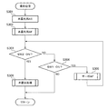
次に図2のフローチャートを使って本発明の電子カメラについて説明する。まずS201ではCPU119が、撮影準備を指示するSW1の状態(ON/OFF)を判定し、該状態がON(オン)状態ならばS205へ進むが、OFF(オフ)状態の場合にはS202へ進む。S202ではCPU119からの制御信号に基づき撮像光学系の駆動制御部により、絞り105やシャッタースピードを制御してモニタ128に表示される画像の明るさが適正になるようAE動作を行う。S203では光源の色温度によらずモニタ128に表示される画像が適切な色バランスになるようにCPU119の制御下でオートホワイトバランス(AWB)動作を行う。S204では撮像素子112から読み出した画像信号に対して所定の処理を施してモニタ128上に画像を表示する。またS205では後述する手順に従って撮影処理を行う。
Next, the electronic camera of the present invention will be described using the flowchart of FIG. First, in S201, the
図3は図2におけるS205の撮影処理を説明するフローチャートである。S301ではCPU119が本露光用AE動作を行う。S302では後述する手順に従ってCPU119が本露光用AF動作を行う。S303においてCPU119は撮影処理指示スイッチSW2の状態(ON/OFF)を判定し、該状態がONならばS306へ進むが、OFF状態の場合にはS304へ進む。S304ではCPU119が撮影準備指示スイッチSW1の状態(ON/OFF)を判定し、該状態がONならばS305へ進むが、OFF状態の場合には本処理を終了する。S305では後述する手順に従ってサーボAF動作を行った後でS303に戻る。S306では後述する手順に従って本露光及び記録を行う。
FIG. 3 is a flowchart for explaining the photographing process of S205 in FIG. In S301, the
図4は図3におけるS302の本露光用AF動作を説明するフローチャートである。まずS401ではCPU119がフォーカスレンズ駆動回路104に送出する制御信号により、フォーカスレンズ101をスキャン開始位置へと移動させる。このスキャン開始位置は例えば合焦可能領域の無限遠端とする。
FIG. 4 is a flowchart for explaining the main-exposure AF operation in S302 in FIG. First, in S401, the
S402では撮像素子112から読み出されたアナログ映像信号をA/D変換器113がデジタル信号に変換し、その出力から画像処理プロセッサ115が輝度信号の高周波成分を抽出し、CPU119はこれを焦点評価値としてワークメモリ126に記憶させる。S403ではフォーカスレンズ101の現在位置を取得してCPU119がワークメモリ126に記憶させる。例えばフォーカスレンズ駆動モータ103にステッピングモータを使用する場合には、フォトインタラプタ102によって検出される初期位置からの相対駆動パルス数をもってフォーカスレンズ101の位置とすることができる。また図示しないロータリーエンコーダ等を用いて絶対位置を測定してフォーカスレンズ101の位置情報を得てもよい。S404にてCPU119はフォーカスレンズ101の現在位置がスキャン終了位置と等しいか調べ、両者が等しい場合にS406へ進むが、そうでなければS405へ進む。なお、このスキャン終了位置は例えば合焦可能領域の至近端とする。S405ではCPU119からフォーカスレンズ駆動回路104に送出される制御信号により、フォーカスレンズ101をスキャン終了方向へ向かって所定量だけ移動させた後、S402に戻る。
In S402, the A /
S406ではCPU119がS402で取得した焦点評価値の中から最大のものを算出する。S407ではS406で算出した焦点評価値の最大値を取得した時のフォーカスレンズ101の位置(以下、これをピーク位置と呼ぶ)をCPU119がワークメモリ126に記憶させる。すなわち、CPU119はフォーカスレンズ101の位置と関連付けて、画像処理プロセッサ115からの出力信号を記憶させる。S408ではCPU119によって実行されるプログラムに従ってS407で記憶したピーク位置を元にカメラから被写体までの距離を算出する。この時、カメラに使用されるレンズの光学特性やAFを行った時のズームレンズ108の焦点距離、製造時の調整データなどを使ってフォーカスレンズ101の位置を、被写体距離(カメラから被写体までの距離)に換算することができる。S409ではCPU119からフォーカスレンズ駆動回路104に送出される制御信号により、S407で記憶したピーク位置へフォーカスレンズ101を移動させる。
In S406, the
図5は図3におけるS305のサーボAF動作を説明するフローチャートである。まずS501においてCPU119は図4のS408で算出した被写体距離を、所定距離、つまり予め決められた閾値(距離基準値)と比較し、被写体距離が閾値より大きい場合にはS502へ進むが、被写体距離が閾値以下の場合にはS505へ進む。S502ではCPU119の制御に従い、サーボAFにおいて合焦動作を繰り返す場合の時間間隔T、すなわち、合焦動作を行った時点から次の合焦動作を行う時点までの時間間隔をT1に設定する。S503では今回の合焦動作におけるスキャン範囲RをR1に設定する。なおスキャン範囲は、ある合焦動作におけるフォーカスレンズの全移動量、すなわち移動範囲に相当する。そしてS504では今回の合焦動作におけるスキャンステップSをS1に設定する。このスキャンステップは、ある合焦動作の期間内にて、輝度信号の高周波成分を表す信号を記憶する度に移動制御されるフォーカスレンズの移動量に相当する。
FIG. 5 is a flowchart for explaining the servo AF operation of S305 in FIG. First, in step S501, the
S505では前記時間間隔TをT2に設定し、S506では前記スキャン範囲RをR2に設定する。S507では前記スキャンステップSをS2に設定する。
S502からS507までの説明において、T1>T2、R1<R2、S1<S2の関係を有するものとする。つまり、CPU119の制御により、以下の条件を満たすように設定を行う。
In S505, the time interval T is set to T2, and in S506, the scan range R is set to R2. In S507, the scan step S is set to S2.
In the description from S502 to S507, it is assumed that T1> T2, R1 <R2, and S1 <S2. In other words, settings are made so as to satisfy the following conditions under the control of the
・時間間隔Tは、被写体までの距離が短い場合に比して当該距離が長い場合に長い。
・スキャン範囲Rは、被写体までの距離が短い場合に比して当該距離が長い場合に狭い。
・スキャンステップSは、被写体までの距離が短い場合に比して当該距離が長い場合に小さい。
The time interval T is longer when the distance is longer than when the distance to the subject is short.
The scan range R is narrower when the distance is longer than when the distance to the subject is short.
The scan step S is smaller when the distance is longer than when the distance to the subject is short.
S508ではCPU119がフォーカスレンズ駆動回路104に信号を送出してフォーカスレンズ101をスキャン開始位置へ移動させる。このスキャン開始位置は「現在位置−R/2」で求められる位置とする。つまり現在位置から、S503またはS506で設定したスキャン範囲Rの2分の1だけフォーカスレンズ101を移動させた位置をスキャン開始位置とする。
In step S508, the
S509では撮像素子112から読み出されたアナログ映像信号を、A/D変換器113を使ってデジタル信号に変換する。そして、その出力を画像処理プロセッサ115に送出することにより、輝度信号の高周波成分を抽出し、CPU119がこれを焦点評価値としてワークメモリ126に記憶させる。S510ではCPU119がフォーカスレンズ101の現在位置を取得してその位置データをワークメモリ126に記憶させる。なおフォーカスレンズ101の駆動にステッピングモータを使用する場合には、フォトインタラプタ102により検出される初期位置からの相対駆動パルス数を位置情報として用いることができるが、ロータリーエンコーダ等を用いて絶対位置を測定してもよい。
In step S <b> 509, the analog video signal read from the
S511においてCPU119は、フォーカスレンズ101の現在位置がスキャン終了位置と等しいか否かを調べ、両位置が等しい場合にはS513へ進むが、異なる場合はS512へ進む。このスキャン終了位置は、「スキャン開始位置+R」で求められる位置とする。S512ではフォーカスレンズ101をスキャン終了方向へ向かって所定量だけ移動させてからS509に戻る。この時の所定量についてはS504またはS507で設定したSとする。
In S511, the
S513ではS509で取得した焦点評価値の中から最大のものをCPU119が算出する。S514ではS513で算出した焦点評価値のうち、その最大値を取得した時点におけるフォーカスレンズ101のピーク位置をCPU119がワークメモリ126に記憶させる。S515ではCPU119の制御により、S514で記憶したピーク位置へとフォーカスレンズ101を移動させる。
In S513, the
S516ではCPU119の制御下でタイマ132をリセットして、タイマカウント値を0にする。S517ではタイマ132が計時を開始する。S518ではCPU119が撮影処理指示スイッチSW2の状態を判定し、該状態がONならば本処理は終了するが、そうでなければS519へ進む。S519ではCPU119が、タイマ132の計測時間と、S502またはS505で設定した合焦動作の時間間隔Tとを比較し、タイマ132の計測時間がT以上ならば本処理を終了するが、そうでなければS518に戻る。
In S516, the
図5に示した制御に従うように装置を構成した場合の動作は次のようになる。まず図4の本露光用AF処理において算出された被写体までの距離に応じて、隣り合う合焦動作同士の時間間隔T、スキャン範囲R、スキャンステップSを設定する。この時、同じ時間内における実空間での移動量が同じであっても、被写体が遠方にある時は被写界深度が深いために、レンズを通過した被写体像の結像位置の移動量は小さくなることを利用して、これらの値を以下のように設定する。 The operation when the apparatus is configured to follow the control shown in FIG. 5 is as follows. First, a time interval T, a scan range R, and a scan step S between adjacent focusing operations are set according to the distance to the subject calculated in the main exposure AF process of FIG. At this time, even if the amount of movement in the same space in the same time is the same, when the subject is far away, the depth of field is deep, so the amount of movement of the imaging position of the subject image that has passed through the lens is These values are set as follows using the smaller value.
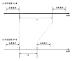
まず被写体までの距離が所定距離(距離基準値であり、以下では閾値という)より遠い場合は、被写体までの距離が近い時よりも前記時間間隔Tを長く設定する。図6はこのようにして設定した時間間隔Tを説明するための図である。被写体までの距離が閾値よりも大きい時には結像位置の移動量が小さいためにピントがボケる(非合焦)までの時間が長くなるので、それに応じて時間間隔Tも長くする。一方、被写体距離が閾値より小さい場合には、同様の理由で時間間隔Tを短く設定する。この時の閾値は例えば1mとする。 First, when the distance to the subject is longer than a predetermined distance (distance reference value, hereinafter referred to as a threshold), the time interval T is set longer than when the distance to the subject is short. FIG. 6 is a diagram for explaining the time interval T set in this way. When the distance to the subject is larger than the threshold value, the amount of movement of the imaging position is small, so the time until the focus is out of focus (out of focus) is lengthened, so the time interval T is also lengthened accordingly. On the other hand, when the subject distance is smaller than the threshold, the time interval T is set short for the same reason. The threshold at this time is, for example, 1 m.
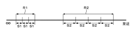
また被写体までの距離が閾値よりも大きい場合は当該距離が閾値よりも小さい場合に比して、スキャン範囲Rを狭く設定する。図7はこのように設定したスキャン範囲Rを説明する図である。このような設定を行う理由は、被写体までの距離が閾値より大きい時は結像位置の移動量が小さいため、狭い移動範囲内でも十分に合焦位置を含むようにスキャンを行えるからである。これによってスキャン時間を短縮できる。一方、被写体までの距離が閾値より小さい場合は、同様の理由でスキャン範囲Rを広く設定する。これによってスキャン範囲Rから合焦位置が外れないように防止できる。 When the distance to the subject is larger than the threshold, the scan range R is set narrower than when the distance is smaller than the threshold. FIG. 7 is a diagram for explaining the scan range R set in this way. The reason for making such a setting is that when the distance to the subject is larger than the threshold, the amount of movement of the imaging position is small, so that the scan can be performed so that the in-focus position is sufficiently included even within a narrow movement range. This can shorten the scan time. On the other hand, when the distance to the subject is smaller than the threshold, the scan range R is set wide for the same reason. As a result, the in-focus position can be prevented from deviating from the scan range R.
さらに、被写体までの距離が閾値より大きい場合は、当該距離が近い場合よりも前記スキャンステップSを小さく設定する。スキャン範囲Rと同様に、図7はこのようにして設定したスキャンステップSを説明する図でもある。前述の説明では、被写体までの距離が閾値より大きい場合において、該距離が近い場合よりもスキャン範囲Rを狭く設定したため、それに応じてスキャンステップSも小さく設定する。こうすることで狭く設定したスキャン範囲R内でも、焦点評価値の取得数について必要十分な数を確保でき、従って、取得した焦点評価値を元に補間演算を行ってピーク位置を算出する場合に有効である。 Further, when the distance to the subject is larger than the threshold, the scanning step S is set smaller than when the distance is close. Similar to the scan range R, FIG. 7 is also a diagram for explaining the scan step S set in this way. In the above description, when the distance to the subject is greater than the threshold value, the scan range R is set narrower than when the distance is close, so the scan step S is also set accordingly. In this way, a necessary and sufficient number of focus evaluation values can be secured even within a narrowly set scan range R. Therefore, when the peak position is calculated by performing an interpolation operation based on the acquired focus evaluation values. It is valid.
なお被写体像の結像位置の移動量はレンズの焦点距離によっても変わるので、前記時間間隔T、スキャン範囲R、スキャンステップSを設定する際の判定に使用する閾値をズームレンズ108の位置に応じて変えてもよい。さらに、同じ焦点距離であっても閾値を複数個持つように設定してもよい。この場合には前記時間間隔T、スキャン範囲R、スキャンステップSの組を3つ以上持つことになる(つまりN個の場合、[Ti、Ri、Si],i=1,2,・・・,N)。
Note that the amount of movement of the image formation position of the subject image also varies depending on the focal length of the lens, so that the threshold used for determination when setting the time interval T, scan range R, and scan step S depends on the position of the
図8は図3のS306における本露光処理を説明するフローチャートである。まずS801における撮像素子112の露光後に、S802では撮像素子112に蓄積されたデータを読み出す。S803ではA/D変換器113を使って撮像素子112から読み出したアナログ信号をデジタル信号に変換する。S804では画像処理プロセッサ115を使って、A/D変換器113から出力されるデジタル信号に対して各種画像処理を施す。S805ではS804で処理した画像をCPU119の制御下でJPEGなどのフォーマットにしたがって圧縮する。S806ではS805で圧縮したデータを記録媒体インターフェース117に送り、これを介して電子カメラ本体に装着されたメモリカードなどの記録媒体118に記録させるようにCPU119が制御を行う。
FIG. 8 is a flowchart for explaining the main exposure process in S306 of FIG. First, after exposure of the
前記ステップS801での撮像素子112による処理は、CPU119が、撮像素子112およびA/D変換器113それぞれに対し、タイミング信号発生回路114を介して、該当する処理にかかわる制御を行うことにより実施される。同様に、ステップS802およびステップS803でのA/D変換器113による処理も、CPUにより制御される。CPU119が、撮像素子112およびA/D変換器113それぞれに対し、タイミング信号発生回路114を介して、該当する処理にかかわる制御を行うことにより実施される。また、ステップS804からステップS806での画像処理プロセッサ115による処理は、CPU119が、画像処理プロセッサ115に対し、該当する処理にかかわる制御を行うことにより実施される。
The processing by the
なお、第1実施形態では、ステップS806の処理については、CPU119が、画像処理プロセッサ115から圧縮データを取得し、この取得した圧縮データを、記録媒体インターフェース117を介して記録媒体118へ記録するようにしてもよい。
In the first embodiment, for the processing in step S 806, the
第1実施形態では、上述した電子カメラの基本的な処理(図2参照)の処理手順に対応するプログラム(メインプログラム)が、プログラムメモリ125に格納されている。
また、撮影処理(図3参照)、本露光用AF処理(図4参照)、サーボAF処理(図5参照)、および本露光処理(図3参照)の各処理手順に対応する各プログラム(サブプログラム)とを含む所定のプログラムもプログラムメモリ125に格納されている。
In the first embodiment, a program (main program) corresponding to the processing procedure of the basic processing (see FIG. 2) of the electronic camera described above is stored in the program memory 125.
In addition, each program (sub) corresponding to each processing procedure of photographing processing (see FIG. 3), main exposure AF processing (see FIG. 4), servo AF processing (see FIG. 5), and main exposure processing (see FIG. 3). A predetermined program including a program) is also stored in the program memory 125.
上記所定のプログラムのうち、本露光用AF処理およびサーボAF処理の各処理手順(図4および図5参照)に対応する各プログラム(サブプログラム)は、上述した焦点調節制御プログラムに対応する。
Among the predetermined programs, each program (subprogram) corresponding to each processing procedure (see FIGS. 4 and 5) of the main exposure AF processing and servo AF processing corresponds to the above-described focus adjustment control program.
そして、CPU119が、焦点調節制御プログラムを含む上記所定のプログラムをプログラムメモリ125から読み出して実行することにより、電子カメラの基本的な処理、撮影処理、本露光用AF処理、サーボAF処理を実施する。また、これとともに、本露光処理に係る構成要素(撮像素子112、A/D変換器113、画像処理プロセッサ115)を制御する。
The
以上説明したように、第1実施形態によれば、被写体までの距離に応じて合焦動作を繰り返す際の時間間隔Tを変えることによって、被写体が遠距離にある場合に無駄な合焦動作を省くことができる。また被写体が近距離にある場合には被写体像が非合焦の状態となる前に合焦動作を行うことができる。さらに被写体までの距離に応じてスキャン範囲Rを変えることによって、被写体が遠距離にある場合にスキャン時間を無駄に長くすることが無くなる。また被写体が近距離にある場合にはスキャン範囲の不足が原因で合焦不能に陥るといったことも無くなる。さらには被写体までの距離に応じてスキャンステップSを変えることによって、スキャン範囲Rに応じた適切な幅のスキャンステップSを設定することができる。こうすることで狭く設定したスキャン範囲内であっても、焦点評価値の取得数を必要な分だけ確保できる。 As described above, according to the first embodiment, by changing the time interval T when the focusing operation is repeated according to the distance to the subject, a wasteful focusing operation is performed when the subject is at a long distance. It can be omitted. Further, when the subject is at a short distance, the focusing operation can be performed before the subject image becomes out of focus. Furthermore, by changing the scan range R according to the distance to the subject, the scan time is not increased unnecessarily when the subject is at a long distance. In addition, when the subject is at a short distance, there is no possibility of being unable to focus due to a lack of scanning range. Furthermore, by changing the scan step S according to the distance to the subject, it is possible to set the scan step S having an appropriate width according to the scan range R. In this way, the necessary number of focus evaluation values can be secured even within a narrow scan range.
次に本発明に係る第2の実施形態について詳述する。
前述の説明では、本露光用AFの結果得られた、被写体までの距離に応じて合焦動作の時間間隔、スキャン範囲、スキャンステップを変えたが、これらを合焦可否の判定結果に応じて変えても良い。このように構成した場合の動作を以下に説明する。
Next, a second embodiment according to the present invention will be described in detail.
In the above description, the time interval, the scan range, and the scan step of the focusing operation are changed according to the distance to the subject obtained as a result of the main exposure AF. You can change it. The operation in such a configuration will be described below.
図9は第1の実施形態における図4の本露光用AF動作を説明するフローチャートを置き換えたものである。まずS901ではCPU119がフォーカスレンズ駆動回路104に信号を送出してフォーカスレンズ101をスキャン開始位置へと移動させる。このスキャン開始位置は例えば合焦可能領域の無限遠端とする。
FIG. 9 replaces the flowchart for explaining the main exposure AF operation of FIG. 4 in the first embodiment. First, in S901, the
S902では撮像素子112から読み出されたアナログ映像信号について、A/D変換器113を使ってデジタル信号に変換する。そして、その出力を画像処理プロセッサ115に送出し、ここで輝度信号の高周波成分を抽出し、CPU119がこれを焦点評価値としてワークメモリ126に記憶させる。S903ではフォーカスレンズ101の現在位置を取得してワークメモリ126に記憶する。なお、フォーカスレンズ101の位置情報の取得については上述の通りである。S904においてCPU119はフォーカスレンズ101の現在位置がスキャン終了位置と等しいか調べ、両位置が等しい場合にはS906へ進むが、そうでなければS905へ進む。このスキャン終了位置としては、例えば合焦可能領域の至近端とする。S905ではCPU119の制御下でフォーカスレンズ101をスキャン終了方向へ向かって所定量だけ移動させる。
In step S <b> 902, the analog video signal read from the
S906ではS902で取得した焦点評価値の中から最大のものをCPU119が算出する。S907ではS906で算出した焦点評価値の最大値をCPU119が所定値(評価基準値)と比較し、最大値が所定値より大きい場合にはS908へ進むが、そうでなければS911へ進む。S908ではS906で算出した焦点評価値の最大値を取得した時のフォーカスレンズ101のピーク位置をCPU119がワークメモリ126に記憶させた後、S909では合焦状態をOK(合焦可能)としてワークメモリ126に記憶させる。S910ではCPU119がフォーカスレンズ駆動回路104に信号を送出し、S908で記憶したピーク位置へとフォーカスレンズ101を移動させる。
In S906, the
S911ではCPU119が合焦状態をNG(合焦不能)としてワークメモリ126に記憶させる。S912ではCPU119がフォーカスレンズ駆動回路104に信号を送出し、所定位置へフォーカスレンズ101を移動させる。この時の所定位置については無限遠を被写界深度の遠端に含む、いわゆる過焦点距離に相当する位置に設定する。または所定位置を合焦可能範囲の中央点に設定しても良い。
In S911, the
図10は図3に示したS305のサーボAF動作を説明するフローチャートを置き換えたものである。まずS1001では図9のS909またはS911で記憶した合焦状態、もしくは後述するS1014またはS1016で記憶する合焦状態をCPU119が調べ、該状態がOK(合焦可能)ならばS1002へ進むが、NG(合焦不能)ならばS1004へ進む。
FIG. 10 replaces the flowchart for explaining the servo AF operation in S305 shown in FIG. First, in S1001, the
S1002では今回の合焦動作におけるスキャン範囲RをCPU119がR3に設定し、次のS1003では今回の合焦動作におけるスキャンステップSをS3に設定する。
他方、S1004では今回の合焦動作におけるスキャン範囲RをCPU119がR4に設定し、次のS1005では今回の合焦動作におけるスキャンステップSをS4に設定する。
In S1002, the
On the other hand, in S1004, the
S1002からS1005までの説明において、R3<R4、S3>S4の関係を有するものとする。つまり、CPU119の制御により、以下の条件を満たすように設定を行う。
・スキャン範囲Rは、合焦可否の判定結果がOKとされた場合に比して該判定結果がNGとされた場合に広く設定する。
・スキャンステップSは、合焦可否の判定結果がOKとされた場合に比して該判定結果がNGとされた場合に小さく設定する。
In the description from S1002 to S1005, it is assumed that there is a relationship of R3 <R4, S3> S4. In other words, settings are made so as to satisfy the following conditions under the control of the
The scan range R is set wider when the determination result is NG than when the focus determination result is OK.
The scan step S is set to be smaller when the determination result is NG than when the focus determination result is OK.
S1006ではCPU119がフォーカスレンズ駆動回路104に信号を送出してフォーカスレンズ101をスキャン開始位置へ移動させる。このスキャン開始位置は、「現在位置−R/2」で求められる位置とする。つまり現在位置から、S1002またはS1004で設定したスキャン範囲Rの2分の1だけフォーカスレンズ101を移動させた位置をスキャン開始位置とする。
In step S1006, the
S1007では撮像素子112から読み出されたアナログ映像信号を、A/D変換器113を使ってデジタル信号に変換する。そして、その出力を画像処理プロセッサ115に送出することにより、輝度信号の高周波成分を抽出し、CPU119がこれを焦点評価値としてワークメモリ126に記憶させる。S1008ではCPU119がフォーカスレンズ101の現在位置を取得してその位置データをワークメモリ126に記憶させる。なお、フォーカスレンズ101の位置情報の取得については上述の通りである。S1009でCPU119は、フォーカスレンズ101の現在位置がスキャン終了位置と等しいか否かを調べ、両位置が等しい場合にはS1011へ進むが、そうでなければS1010へ進む。このスキャン終了位置は、「スキャン開始位置+R」で求められる位置とする。S1010ではフォーカスレンズ101をスキャン終了方向へ向かって所定量だけ移動させる。この時の所定量についてはS1003またはS1005で設定したSとする。
In step S <b> 1007, the analog video signal read from the
S1011ではS1007で取得した焦点評価値の中から最大のものをCPU119が算出する。S1012ではS1011で算出した焦点評価値の最大値を所定値(評価基準値)と比較し、最大値が所定値より大きい場合にはS1013へ進むが、そうでなければS1016へ進む。S1013ではS1011で算出した焦点評価値のうち、その最大値を取得した時点におけるフォーカスレンズ101のピーク位置をCPU119がワークメモリ126に記憶させる。S1014では合焦状態をOKとしてこれをCPU119がワークメモリ126に記憶させる。S1015ではCPU119がフォーカスレンズ駆動回路104に信号を送出し、S1013で記憶したピーク位置へとフォーカスレンズ101を移動させる。
In S1011, the
S1016ではCPU119が合焦状態をNGとしてワークメモリ126に記憶させる。S1017ではCPU119がフォーカスレンズ駆動回路104に信号を送出し、所定位置へフォーカスレンズ101を移動させる。この時の所定位置については無限遠を被写界深度の遠端に含む、いわゆる過焦点距離に相当する位置に設定する。または所定位置を合焦可能範囲の中央点に設定しても良い。
In S1016, the
S1018ではCPU119の制御下でタイマ132をリセットして、タイマカウント値を0にする。S1019ではタイマ132が計時を開始する。S1020ではCPU119が撮影処理指示スイッチSW2の状態を判定し、該状態がONならば本処理は終了するが、そうでなければS1021へ進む。S1021ではCPU119が、タイマ132の計測時間と所定時間(比較基準時間)を比較し、タイマ132の計測時間が所定時間以上ならば本処理を終了するが、そうでなければS1020に戻る。
In step S1018, the
図10のように構成した場合の動作は次のようになる。まず図9の本露光用AF処理において判定された合焦状態に応じて、CPU119はスキャン範囲R、スキャンステップSを設定する。
The operation when configured as shown in FIG. 10 is as follows. First, the
この時、スキャン範囲Rは合焦状態がOKである場合の方がNGの場合に比べて狭くなっている。図11はこれを説明する図である。この理由は、合焦状態がOKであれば合焦位置が分かっているので、次のスキャンを行う際に前回の合焦位置の近傍だけをスキャンすれば合焦位置を検出できるからである。これによって合焦動作に無駄な時間をかけずに済む。一方、合焦状態がNGの場合には合焦位置が事前にわからないので、次のスキャンではより広い範囲をスキャンすることによって、合焦位置を検出できる可能性が高くなる。 At this time, the scan range R is narrower when the in-focus state is OK than when it is NG. FIG. 11 is a diagram for explaining this. This is because if the in-focus state is OK, the in-focus position is known, so that when the next scan is performed, the in-focus position can be detected by scanning only the vicinity of the previous in-focus position. This eliminates wasted time for the focusing operation. On the other hand, since the in-focus position is not known in advance when the in-focus state is NG, it is highly possible that the in-focus position can be detected by scanning a wider range in the next scan.
また、スキャンステップSは合焦状態がNGである場合の方がOKの場合に比べて狭くなっている。この理由は、合焦状態がNGの場合にはOKの場合よりもスキャンステップSを狭くすることで合焦位置の検出精度をより高くすることができ、従って次の合焦動作において合焦状態がOKとなる可能性が高まるからである。 Further, the scan step S is narrower when the in-focus state is NG than when it is OK. This is because, when the in-focus state is NG, the detection accuracy of the in-focus position can be made higher by narrowing the scan step S than in the case of OK, and therefore, the in-focus state in the next in-focus operation. This is because there is a higher possibility that will become OK.
第2実施形態では、上述した電子カメラの基本的な処理(図2参照)の処理手順に対応するプログラム(メインプログラム)がプログラムメモリ125に格納されている。
また、撮影処理(図3参照)、本露光用AF処理(図9参照)、サーボAF処理(図10参照)、および本露光処理(図8参照)の各処理手順に対応する各プログラム(サブプログラム)とを含む所定のプログラムもプログラムメモリ125に格納されている。
In the second embodiment, a program (main program) corresponding to the processing procedure of the basic processing (see FIG. 2) of the electronic camera described above is stored in the program memory 125.
Further, each program (sub) corresponding to each processing procedure of the photographing process (see FIG. 3), the main exposure AF process (see FIG. 9), the servo AF process (see FIG. 10), and the main exposure process (see FIG. 8). A predetermined program including a program) is also stored in the program memory 125.
上記所定のプログラムのうち、本露光用AF処理およびサーボAF処理の各処理手順(図9および図10参照)に対応する各プログラム(サブプログラム)は、上述した焦点調節制御プログラムに対応する。
Among the predetermined programs, each program (subprogram) corresponding to each processing procedure (see FIGS. 9 and 10) of the main exposure AF process and the servo AF process corresponds to the above-described focus adjustment control program.
そして、CPU119が、焦点調節制御プログラムを含む上記所定のプログラムをプログラムメモリ125から読み出して実行する。これにより、電子カメラの基本的な処理、撮影処理、本露光用AF処理、サーボAF処理を実施するとともに、本露光処理に係る構成要素(撮像素子112、A/D変換器113、画像処理プロセッサ115)を制御する。
The
この第2実施形態では、合焦状態の判定を行い、その結果の如何に応じてスキャン範囲を変えることによって、合焦動作を効率良く行え、合焦位置を検出できる可能性が高まることになる。また合焦位置の検出精度をより高くすることができる。 In the second embodiment, by determining the in-focus state and changing the scan range according to the result, it is possible to efficiently perform the in-focus operation and to detect the in-focus position. . In addition, the detection accuracy of the in-focus position can be further increased.
本願明細書では、上述した焦点調節制御プログラム(上述した制御機能を実現するためのソフトウェア)などのプログラムを記録媒体としてのプログラムメモリに記録する実施形態として説明した。しかし、少なくとも焦点調節制御プログラムを次のようにして提供することも可能である。
The present specification has been described as an embodiment in which a program such as the above-described focus adjustment control program (software for realizing the above-described control function) is recorded in a program memory as a recording medium. However, at least the focus adjustment control program can be provided as follows.
すなわち、少なくとも上記焦点調節制御プログラムをメモリカードなどなどのコンピュータ読み取り可能な記録媒体(例えば着脱可能な記録媒体118に対応)に格納して配布するようにしてもよい。この場合、その記録媒体に記録されたプログラムをCPUがインストールした後、このプログラムをCPUが実行するようにする。このプログラム(少なくとも焦点調節制御プログラム)のインストール先としては、RAM等のメモリなどの記憶装置がある。
That is, at least the focus adjustment control program may be stored in a computer-readable recording medium such as a memory card (for example, corresponding to the removable recording medium 118) and distributed. In this case, after the CPU installs the program recorded on the recording medium, the CPU executes the program. As an installation destination of this program (at least the focus adjustment control program), there is a storage device such as a memory such as a RAM.
また、電子カメラを通信回線(例えばケーブル等の有線通信回線、無線通信回線)を介して、電子カメラ外部のプログラム提供装置、例えばコンピュータと接続してもよい。そして、当該電子カメラ(のCPU)が、コンピュータから上記少なくとも焦点調節制御プログラムをダウンロードした後、このプログラムを実行してもよい。このプログラム(少なくとも焦点調節制御プログラム)のダウンロード先としては、RAM等のメモリなどの記憶装置がある。
In addition, the electronic camera may be connected to a program providing apparatus outside the electronic camera , for example, a computer , via a communication line (for example, a wired communication line such as a cable or a wireless communication line). Then, the electronic camera (CPU of the) is, after downloading the at least focusing control program from the computer, may execute this program. As a download destination of this program (at least the focus adjustment control program), there is a storage device such as a memory such as a RAM.
101 フォーカスレンズ
103、104 駆動部
112 光電変換部(撮像素子)
115、116 抽出部
119、125、126 制御部
101
115, 116
Claims (6)
前記光電変換手段の出力信号から高周波成分を抽出して焦点信号を生成する抽出手段と、
フォーカスレンズを移動させて前記焦点信号を順次取得するスキャン動作を行い、前記取得された焦点信号に基づいて前記フォーカスレンズの移動を制御することにより焦点調節動作を行う制御手段とを有し、
前記焦点調節動作の開始が指示されてから撮影動作が指示されるまでの間、前記制御手段が繰り返し行う前記焦点調節動作中に、
前記制御手段は、前記焦点信号に基づいて合焦可否を判定し、合焦可能と判定した場合には次の焦点調節動作における前記フォーカスレンズの移動範囲を第1の範囲に設定し、合焦不能と判定した場合には次の焦点調節動作における前記フォーカスレンズの移動範囲を前記第1の範囲よりも広く全域よりも狭い第2の範囲に設定することを特徴とする自動焦点調節装置。 Photoelectric conversion means for converting a subject image into an electrical signal;
Extraction means for extracting a high frequency component from an output signal of the photoelectric conversion means to generate a focus signal;
By moving the focus lens performs a scanning operation for sequentially acquiring the focus signal, and a control means for focusing operation by controlling the movement of the focus lens based on the obtained focus signal,
During the focus adjustment operation that is repeatedly performed by the control unit, from the start of the focus adjustment operation until the shooting operation is instructed,
The control means determines whether or not focusing is possible based on the focus signal, and when it is determined that focusing is possible, the moving range of the focus lens in the next focus adjustment operation is set to a first range, and focusing is performed. An automatic focus adjusting apparatus characterized in that if it is determined to be impossible, the movement range of the focus lens in the next focus adjustment operation is set to a second range that is wider than the first range and narrower than the entire range.
フォーカスレンズを移動させて前記焦点信号を順次取得するスキャン動作を行い、前記取得された焦点信号に基づいて前記フォーカスレンズの移動を制御することにより焦点調節動作を行う制御ステップとを有し、
前記焦点調節動作の開始が指示されてから撮影動作が指示されるまでの間、前記制御ステップにおいて繰り返し行う前記焦点調節動作中に、前記抽出ステップで生成される前記焦点信号に基づいて合焦可否を判定する判定ステップと、前記判定ステップで合焦可能と判定された場合に次の焦点調節動作における前記フォーカスレンズの移動範囲を第1の範囲に設定するステップと、前記判定ステップで合焦不能と判定された場合に次の焦点調節動作における前記フォーカスレンズの移動範囲を前記第1の範囲よりも広く全域よりも狭い第2の範囲に設定するステップを有することを特徴とする自動焦点調節装置の制御方法。 An extraction step for generating a focus signal by extracting a high-frequency component from an output signal obtained by converting a subject image into an electrical signal;
By moving the focus lens performs a scanning operation for sequentially acquiring the focus signal, and a control step of performing focus adjustment by controlling the movement of the focus lens based on the obtained focus signal,
Whether or not focusing is possible based on the focus signal generated in the extraction step during the focus adjustment operation repeatedly performed in the control step from when the start of the focus adjustment operation is instructed until the shooting operation is instructed. A determination step for determining whether or not focusing is possible in the determination step, a step of setting the movement range of the focus lens in a next focus adjustment operation to a first range, and inability to focus in the determination step And a step of setting the movement range of the focus lens in the next focus adjustment operation to a second range that is wider than the first range and narrower than the entire area when it is determined that Control method.
前記焦点調節動作の開始が指示されてから撮影動作が指示されるまでの間、前記制御ステップにおいて繰り返し行う前記焦点調節動作中に、前記抽出ステップで生成される前記焦点信号に基づいて合焦可否を判定する判定ステップと、前記判定ステップで合焦可能と判定された場合に次の焦点調節動作における前記フォーカスレンズの移動範囲を第1の範囲に設定するステップと、前記判定ステップで合焦不能と判定された場合に次の焦点調節動作における前記フォーカスレンズの移動範囲を前記第1の範囲よりも広く全域よりも狭い第2の範囲に設定するステップを有することを特徴とする焦点調節制御プログラム。
An extraction step for extracting a high frequency component from an output signal obtained by converting an object image into an electrical signal to generate a focus signal, a scan operation for sequentially acquiring the focus signal by moving a focus lens, and the acquired focus signal a focus adjustment control program for executing a control step of performing focus adjustment operation in the computer by controlling the movement of the focus lens based on,
Whether or not focusing is possible based on the focus signal generated in the extraction step during the focus adjustment operation repeatedly performed in the control step from when the start of the focus adjustment operation is instructed until the shooting operation is instructed. A determination step for determining whether or not focusing is possible in the determination step, a step of setting the movement range of the focus lens in a next focus adjustment operation to a first range, and inability to focus in the determination step And a step of setting the moving range of the focus lens in the next focus adjustment operation to a second range that is wider than the first range and narrower than the entire area when it is determined that .
Priority Applications (4)
| Application Number | Priority Date | Filing Date | Title |
|---|---|---|---|
| JP2008235786A JP5408936B2 (en) | 2008-09-13 | 2008-09-13 | Automatic focus adjustment device, control method of automatic focus adjustment device, and focus adjustment control program |
| CN200910169438.1A CN101672974B (en) | 2008-09-13 | 2009-09-09 | Autofocus apparatus and method for controlling the same |
| CN201310088659.2A CN103207441B (en) | 2008-09-13 | 2009-09-09 | Automatic focusing system and control method thereof |
| US12/558,358 US8521015B2 (en) | 2008-09-13 | 2009-09-11 | Autofocus apparatus and method for controlling the same |
Applications Claiming Priority (1)
| Application Number | Priority Date | Filing Date | Title |
|---|---|---|---|
| JP2008235786A JP5408936B2 (en) | 2008-09-13 | 2008-09-13 | Automatic focus adjustment device, control method of automatic focus adjustment device, and focus adjustment control program |
Publications (3)
| Publication Number | Publication Date |
|---|---|
| JP2010066737A JP2010066737A (en) | 2010-03-25 |
| JP2010066737A5 JP2010066737A5 (en) | 2011-09-15 |
| JP5408936B2 true JP5408936B2 (en) | 2014-02-05 |
Family
ID=42007312
Family Applications (1)
| Application Number | Title | Priority Date | Filing Date |
|---|---|---|---|
| JP2008235786A Active JP5408936B2 (en) | 2008-09-13 | 2008-09-13 | Automatic focus adjustment device, control method of automatic focus adjustment device, and focus adjustment control program |
Country Status (3)
| Country | Link |
|---|---|
| US (1) | US8521015B2 (en) |
| JP (1) | JP5408936B2 (en) |
| CN (2) | CN103207441B (en) |
Families Citing this family (21)
| Publication number | Priority date | Publication date | Assignee | Title |
|---|---|---|---|---|
| JP5408936B2 (en) * | 2008-09-13 | 2014-02-05 | キヤノン株式会社 | Automatic focus adjustment device, control method of automatic focus adjustment device, and focus adjustment control program |
| JP5621325B2 (en) * | 2010-05-28 | 2014-11-12 | ソニー株式会社 | FOCUS CONTROL DEVICE, FOCUS CONTROL METHOD, LENS DEVICE, FOCUS LENS DRIVING METHOD, AND PROGRAM |
| KR101710633B1 (en) * | 2011-08-05 | 2017-02-27 | 삼성전자주식회사 | Auto focus adjusting method, auto focus adjusting apparatus, and digital photographing apparatus including the same |
| JP5325966B2 (en) * | 2011-11-25 | 2013-10-23 | オリンパス株式会社 | Imaging apparatus and imaging method |
| US9784577B2 (en) * | 2012-03-16 | 2017-10-10 | Lg Innotek Co., Ltd. | Measuring distance from object by using size of pattern projected onto object |
| CN103424978A (en) * | 2012-05-15 | 2013-12-04 | 鸿富锦精密工业(深圳)有限公司 | System and method for testing camera module |
| US9392158B2 (en) * | 2012-10-04 | 2016-07-12 | Nvidia Corporation | Method and system for intelligent dynamic autofocus search |
| US9621780B2 (en) | 2012-10-04 | 2017-04-11 | Nvidia Corporation | Method and system of curve fitting for common focus measures |
| CN102891966B (en) * | 2012-10-29 | 2015-07-01 | 珠海全志科技股份有限公司 | Focusing method and device for digital imaging device |
| JP6489817B2 (en) * | 2014-12-10 | 2019-03-27 | キヤノン株式会社 | Imaging apparatus and control method thereof |
| CN104796616A (en) * | 2015-04-27 | 2015-07-22 | 惠州Tcl移动通信有限公司 | Focusing method and focusing system based on distance sensor of mobile terminal |
| JP6474693B2 (en) * | 2015-06-19 | 2019-02-27 | オリンパス株式会社 | Focus detection apparatus, focus detection method, and recording medium |
| CN105872363A (en) * | 2016-03-28 | 2016-08-17 | 广东欧珀移动通信有限公司 | Adjustingmethod and adjusting device of human face focusing definition |
| JP6752681B2 (en) * | 2016-10-19 | 2020-09-09 | キヤノン株式会社 | Display control device, control method and program of display control device, and storage medium |
| CN106773100A (en) * | 2017-01-09 | 2017-05-31 | 成都曙光光纤网络有限责任公司 | A kind of automatic focusing mechanism and method suitable for transmission-type THz wave system |
| CN107748428A (en) * | 2017-10-18 | 2018-03-02 | 歌尔股份有限公司 | Screen detects Atomatic focusing method and device |
| DE102018114388A1 (en) * | 2018-06-15 | 2019-12-19 | Valeo Schalter Und Sensoren Gmbh | Method for controlling a drive device of a micro-oscillating mirror, control device and deflecting mirror device |
| JP7346135B2 (en) * | 2019-07-30 | 2023-09-19 | キヤノン株式会社 | Electronic devices, control methods for electronic devices, programs and storage media |
| WO2021244550A1 (en) * | 2020-06-01 | 2021-12-09 | 王浩 | Automatic focusing apparatus and focusing method |
| CN113358056B (en) * | 2021-05-31 | 2023-06-27 | 深圳中科飞测科技股份有限公司 | Scanning method, scanning system and storage medium for workpiece surface morphology |
| CN115442512A (en) * | 2021-06-04 | 2022-12-06 | 北京小米移动软件有限公司 | Focusing control method, device, terminal and storage medium |
Family Cites Families (12)
| Publication number | Priority date | Publication date | Assignee | Title |
|---|---|---|---|---|
| KR0147572B1 (en) * | 1992-10-09 | 1998-09-15 | 김광호 | Method & apparatus for object tracing |
| JPH11326744A (en) * | 1998-05-18 | 1999-11-26 | Minolta Co Ltd | Autofocusing camera |
| JP3851027B2 (en) * | 1999-08-27 | 2006-11-29 | 株式会社リコー | Autofocus device and camera |
| JP4689051B2 (en) * | 2001-01-19 | 2011-05-25 | キヤノン株式会社 | Focus adjustment device |
| JP3797543B2 (en) * | 2001-10-26 | 2006-07-19 | 富士写真フイルム株式会社 | Automatic focus adjustment device |
| JP2003156679A (en) * | 2001-11-22 | 2003-05-30 | Minolta Co Ltd | Focus detector |
| JP4374826B2 (en) * | 2002-04-26 | 2009-12-02 | 株式会社ニコン | camera |
| JP2003329916A (en) * | 2002-05-14 | 2003-11-19 | Canon Inc | Device and method for picking up image, recording medium, and program |
| JP4674472B2 (en) * | 2005-01-18 | 2011-04-20 | 株式会社ニコン | Digital camera |
| JP4555255B2 (en) | 2006-05-15 | 2010-09-29 | 株式会社リコー | Automatic focusing device, digital camera, portable information input device, focusing position detection method, and computer-readable recording medium |
| JP5408936B2 (en) * | 2008-09-13 | 2014-02-05 | キヤノン株式会社 | Automatic focus adjustment device, control method of automatic focus adjustment device, and focus adjustment control program |
| JP5376986B2 (en) * | 2009-02-17 | 2013-12-25 | キヤノン株式会社 | Focus adjustment device and focus adjustment method |
-
2008
- 2008-09-13 JP JP2008235786A patent/JP5408936B2/en active Active
-
2009
- 2009-09-09 CN CN201310088659.2A patent/CN103207441B/en active Active
- 2009-09-09 CN CN200910169438.1A patent/CN101672974B/en not_active Expired - Fee Related
- 2009-09-11 US US12/558,358 patent/US8521015B2/en active Active
Also Published As
| Publication number | Publication date |
|---|---|
| JP2010066737A (en) | 2010-03-25 |
| US20100067890A1 (en) | 2010-03-18 |
| US8521015B2 (en) | 2013-08-27 |
| CN103207441B (en) | 2016-03-02 |
| CN101672974A (en) | 2010-03-17 |
| CN101672974B (en) | 2014-09-24 |
| CN103207441A (en) | 2013-07-17 |
Similar Documents
| Publication | Publication Date | Title |
|---|---|---|
| JP5408936B2 (en) | Automatic focus adjustment device, control method of automatic focus adjustment device, and focus adjustment control program | |
| JP3728241B2 (en) | Focus adjustment apparatus, imaging apparatus, focusing method, program, and storage medium | |
| JP5789098B2 (en) | Focus detection apparatus and control method thereof | |
| JP2008015274A (en) | Digital camera | |
| JP5002412B2 (en) | Imaging device | |
| JP2015094925A (en) | Focus adjustment device, focus adjustment method and program, and imaging device having focus adjustment device | |
| JP5213813B2 (en) | IMAGING DEVICE AND IMAGING DEVICE CONTROL METHOD | |
| JP2011248159A (en) | Imaging apparatus, imaging system, imaging apparatus control method and program | |
| JP5095519B2 (en) | Imaging apparatus and imaging method | |
| CN107231513B (en) | Image pickup system, image pickup apparatus, lens device, and control method thereof | |
| JP6727453B2 (en) | IMAGING DEVICE, IMAGING DEVICE CONTROL METHOD, AND IMAGING DEVICE CONTROL PROGRAM | |
| JP5787634B2 (en) | Imaging device | |
| JP6234016B2 (en) | Focus adjustment device, imaging device, and control method thereof | |
| JP2016057463A (en) | Focus adjustment device and control method of the same | |
| JP2010028281A (en) | Camera, noise elimination method and noise elimination program | |
| WO2019181024A1 (en) | Image-capturing device, image-capturing method, and program | |
| JP4555255B2 (en) | Automatic focusing device, digital camera, portable information input device, focusing position detection method, and computer-readable recording medium | |
| JP6105917B2 (en) | Focus adjustment apparatus and method, and imaging apparatus | |
| CN113728613B (en) | Imaging element, imaging device, method for operating imaging element, and program | |
| JP6653790B2 (en) | Imaging device, imaging method, and program | |
| JP5868163B2 (en) | IMAGING DEVICE, IMAGING DEVICE CONTROL METHOD, PROGRAM | |
| JP4574726B2 (en) | Imaging apparatus and automatic focusing control method | |
| JP6808501B2 (en) | Imaging device and control method of imaging device | |
| JP5907610B2 (en) | Optical equipment | |
| JP2013130818A (en) | Automatic focusing device, control method thereof and program |
Legal Events
| Date | Code | Title | Description |
|---|---|---|---|
| A521 | Request for written amendment filed |
Free format text: JAPANESE INTERMEDIATE CODE: A523 Effective date: 20110802 |
|
| A621 | Written request for application examination |
Free format text: JAPANESE INTERMEDIATE CODE: A621 Effective date: 20110802 |
|
| A977 | Report on retrieval |
Free format text: JAPANESE INTERMEDIATE CODE: A971007 Effective date: 20120314 |
|
| A131 | Notification of reasons for refusal |
Free format text: JAPANESE INTERMEDIATE CODE: A131 Effective date: 20120321 |
|
| A521 | Request for written amendment filed |
Free format text: JAPANESE INTERMEDIATE CODE: A523 Effective date: 20120518 |
|
| A131 | Notification of reasons for refusal |
Free format text: JAPANESE INTERMEDIATE CODE: A131 Effective date: 20121120 |
|
| A521 | Request for written amendment filed |
Free format text: JAPANESE INTERMEDIATE CODE: A523 Effective date: 20130118 |
|
| A131 | Notification of reasons for refusal |
Free format text: JAPANESE INTERMEDIATE CODE: A131 Effective date: 20130604 |
|
| A521 | Request for written amendment filed |
Free format text: JAPANESE INTERMEDIATE CODE: A523 Effective date: 20130805 |
|
| TRDD | Decision of grant or rejection written | ||
| A01 | Written decision to grant a patent or to grant a registration (utility model) |
Free format text: JAPANESE INTERMEDIATE CODE: A01 Effective date: 20131008 |
|
| A61 | First payment of annual fees (during grant procedure) |
Free format text: JAPANESE INTERMEDIATE CODE: A61 Effective date: 20131105 |
|
| R151 | Written notification of patent or utility model registration |
Ref document number: 5408936 Country of ref document: JP Free format text: JAPANESE INTERMEDIATE CODE: R151 |