JP5213813B2 - IMAGING DEVICE AND IMAGING DEVICE CONTROL METHOD - Google Patents
IMAGING DEVICE AND IMAGING DEVICE CONTROL METHOD Download PDFInfo
- Publication number
- JP5213813B2 JP5213813B2 JP2009189154A JP2009189154A JP5213813B2 JP 5213813 B2 JP5213813 B2 JP 5213813B2 JP 2009189154 A JP2009189154 A JP 2009189154A JP 2009189154 A JP2009189154 A JP 2009189154A JP 5213813 B2 JP5213813 B2 JP 5213813B2
- Authority
- JP
- Japan
- Prior art keywords
- subject
- focus
- change
- size
- focus lens
- Prior art date
- Legal status (The legal status is an assumption and is not a legal conclusion. Google has not performed a legal analysis and makes no representation as to the accuracy of the status listed.)
- Expired - Fee Related
Links
Images


Classifications
-
- G—PHYSICS
- G02—OPTICS
- G02B—OPTICAL ELEMENTS, SYSTEMS OR APPARATUS
- G02B7/00—Mountings, adjusting means, or light-tight connections, for optical elements
- G02B7/28—Systems for automatic generation of focusing signals
- G02B7/36—Systems for automatic generation of focusing signals using image sharpness techniques, e.g. image processing techniques for generating autofocus signals
-
- G—PHYSICS
- G03—PHOTOGRAPHY; CINEMATOGRAPHY; ANALOGOUS TECHNIQUES USING WAVES OTHER THAN OPTICAL WAVES; ELECTROGRAPHY; HOLOGRAPHY
- G03B—APPARATUS OR ARRANGEMENTS FOR TAKING PHOTOGRAPHS OR FOR PROJECTING OR VIEWING THEM; APPARATUS OR ARRANGEMENTS EMPLOYING ANALOGOUS TECHNIQUES USING WAVES OTHER THAN OPTICAL WAVES; ACCESSORIES THEREFOR
- G03B13/00—Viewfinders; Focusing aids for cameras; Means for focusing for cameras; Autofocus systems for cameras
- G03B13/32—Means for focusing
- G03B13/34—Power focusing
- G03B13/36—Autofocus systems
-
- H—ELECTRICITY
- H04—ELECTRIC COMMUNICATION TECHNIQUE
- H04N—PICTORIAL COMMUNICATION, e.g. TELEVISION
- H04N23/00—Cameras or camera modules comprising electronic image sensors; Control thereof
- H04N23/60—Control of cameras or camera modules
- H04N23/67—Focus control based on electronic image sensor signals
- H04N23/673—Focus control based on electronic image sensor signals based on contrast or high frequency components of image signals, e.g. hill climbing method
Description
本発明は撮像装置及び撮像装置の制御方法に関し、特に、撮影待機中にピント合わせを行うために用いて好適な技術に関する。 The present invention relates to an imaging apparatus and a method for controlling the imaging apparatus, and more particularly to a technique suitable for use in focusing during imaging standby.
従来から、電子スチルカメラやビデオカメラなどではオートフォーカス(以下、AFという)を行う場合、CCDなどの撮像素子から得られる輝度信号の高域周波数成分(以下、AF評価値という)が最大になるレンズ位置を合焦位置とする方式が用いられている。この方式の一つとして次のスキャン方式が知られている。 Conventionally, when autofocus (hereinafter referred to as AF) is performed in an electronic still camera or a video camera, the high frequency component (hereinafter referred to as AF evaluation value) of a luminance signal obtained from an image pickup device such as a CCD is maximized. A method is used in which the lens position is the in-focus position. As one of these methods, the following scan method is known.
第1のスキャン方式は、スキャン範囲の全域に亘ってフォーカスレンズを駆動しながら撮像素子内の所定領域(以下、AF枠という)から得られるAF評価値を記憶していく。そして、記憶したAF評価値のうち、その極大値に相当するフォーカスレンズ位置(以下、ピーク位置という)を合焦位置とするスキャン方式である。ここで、合焦位置とは被写体にピントがあうと想定されるレンズ位置のことである。 In the first scan method, an AF evaluation value obtained from a predetermined area (hereinafter referred to as an AF frame) in the image sensor is stored while driving the focus lens over the entire scan range. In the scan method, a focus lens position (hereinafter referred to as a peak position) corresponding to the maximum value among the stored AF evaluation values is used as a focus position. Here, the in-focus position is a lens position where the subject is assumed to be in focus.
第2のスキャン方式として、撮像素子から得られる画像信号を用いて合焦すべき被写体を検出し、その検出した被写体の情報(サイズ、位置)に基づいて、AFを行うことで高速にピントを合わせる技術がある。 As a second scanning method, a subject to be focused is detected using an image signal obtained from an image sensor, and AF is performed at high speed based on information (size, position) of the detected subject. There is technology to match.
例えば、検出した顔サイズに基づいて、概算距離を求める。そして、求められた距離に基づいてスキャン開始点となる位置を決定し、その位置よりも遠側をスキャンしないことで、AF時間を短縮する技術が特許文献1において開示されている。
また、例えば、検出した顔のサイズの時系列変化に基づいて、フォーカスレンズのスキャンの探索範囲を設定する技術が特許文献2で開示されている。
For example, the approximate distance is obtained based on the detected face size. Patent Document 1 discloses a technique for shortening the AF time by determining a position to be a scan start point based on the obtained distance and not scanning the far side from the position.
Further, for example, Patent Literature 2 discloses a technique for setting a focus lens scan search range based on a time-series change in the detected face size.
しかしながら、前述の特許文献1により開示されたデジタルカメラ,及び特許文献2により開示された撮像装置のような従来技術では、被写体のサイズに基づいてスキャン範囲、または探索範囲の設定を行っている。このため、被写体の位置が変化すると、主要被写体の遠方の背景に外してしまう背景抜けが発生する可能性がある。 However, in the conventional techniques such as the digital camera disclosed in Patent Document 1 and the imaging apparatus disclosed in Patent Document 2, the scan range or search range is set based on the size of the subject. For this reason, when the position of the subject is changed, there is a possibility that a background drop occurs that is removed from the background far away from the main subject.
これは、被写体の位置が変化した場合、AF枠が被写体から外れてしまう可能性が高いからである。
本発明は前述の問題点に鑑み、被写体の位置が変化した状態においても背景抜けを防止できるようにすることを目的とする。
This is because there is a high possibility that the AF frame will be detached from the subject when the position of the subject changes.
The present invention has been made in view of the above-described problems, and it is an object of the present invention to prevent background loss even when the position of a subject has changed.
上記の目的を達成するために、本発明の一側面としての撮像装置は、フォーカスレンズを介して入射した被写体像を光電変換して画像データを取得する撮像手段と、前記撮像手段により得られた画像データより被写体のサイズ及び前記被写体の位置を検出する検出手段と、前記フォーカスレンズを連続的に移動させながら、前記画像データに基づいて前記フォーカスレンズの焦点状態を示す焦点信号を取得し、前記焦点信号に基づいて前記フォーカスレンズを移動させて焦点調節を行う制御手段と、を有し、前記制御手段は、前記被写体のサイズの変化を判断するステップを行った後に前記被写体の位置の変化を判断するステップを行っている撮像装置であって、前記焦点調節は、前記被写体に追従しながら前記フォーカスレンズのスキャン範囲の中心位置を移動させており、前記焦点調節のフォーカスレンズのスキャン範囲は、前記フォーカスレンズの移動範囲よりも狭く、前記制御手段は、前記検出した被写体のサイズが変化しない場合、前記検出した被写体の位置が変化しても変化しなくても、前記焦点調節を行わず、前記検出した被写体のサイズが変化した場合、前記検出した被写体の位置が変化しても変化しなくても、前記フォーカスレンズを移動させながら焦点信号を取得する際のフォーカスレンズを移動させており、前記検出した被写体のサイズが変化し前記検出した被写体の位置が変化した場合、前記検出した被写体のサイズが変化し前記検出した被写体の位置が変化しない場合に比べて前記フォーカスレンズを移動させながら焦点信号を取得する際のフォーカスレンズの移動範囲を狭めるように制御することを特徴とする。
また、本発明の別の側面としての制御方法は、フォーカスレンズを介して入射した被写体像を光電変換して画像データを取得する撮像工程と、前記撮像工程により得られた画像データより被写体のサイズ及び前記被写体の位置を検出する検出工程と、前記フォーカスレンズを連続的に移動させながら、前記画像データに基づいて前記フォーカスレンズの焦点状態を示す焦点信号を取得し、前記焦点信号に基づいて前記フォーカスレンズを移動させて焦点調節を行う制御工程と、を有し、前記制御工程は、前記被写体のサイズの変化を判断するステップを行った後に前記被写体の位置の変化を判断するステップを行っている撮像装置の制御方法であって、前記焦点調節は、前記被写体に追従しながら前記フォーカスレンズのスキャン範囲の中心位置を移動させており、前記焦点調節のフォーカスレンズのスキャン範囲は、前記フォーカスレンズの移動範囲よりも狭く、前記制御工程は、前記検出した被写体のサイズが変化しない場合、前記検出した被写体の位置が変化しても変化しなくても、前記焦点調節を行わず、前記検出した被写体のサイズが変化した場合、前記検出した被写体の位置が変化しても変化しなくても、前記フォーカスレンズを移動させながら焦点信号を取得する際のフォーカスレンズを移動させており、前記検出した被写体のサイズが変化し前記検出した被写体の位置が変化した場合、前記検出した被写体のサイズが変化し前記検出した被写体の位置が変化しない場合に比べて前記フォーカスレンズを移動させながら焦点信号を取得する際のフォーカスレンズの移動範囲を狭めるように制御していることを特徴とする。
In order to achieve the above object, an imaging apparatus according to an aspect of the present invention is obtained by an imaging unit that photoelectrically converts a subject image incident through a focus lens to acquire image data, and the imaging unit. A detection means for detecting the size of the subject and the position of the subject from image data, and a focus signal indicating a focus state of the focus lens based on the image data while continuously moving the focus lens, Control means for adjusting the focus by moving the focus lens based on a focus signal, and the control means performs a step of determining a change in the size of the subject and then changes the position of the subject. An imaging apparatus performing a determination step, wherein the focus adjustment is performed by scanning the focus lens while following the subject. And moving the center position of the circumference, the scanning range of the focus lens of the focusing is narrower than the moving range of the focus lens, wherein, if the size of the object the detected does not change, and the detected Even if the position of the subject changes or does not change, the focus adjustment is not performed, and the size of the detected subject changes. When the focus lens for acquiring a focus signal is moved while moving the focus lens, and the size of the detected subject changes and the position of the detected subject changes, the size of the detected subject changes. Focus when acquiring the focus signal while moving the focus lens compared to the case where the position of the detected subject does not change And controlling so as to narrow the moving range of the lens.
According to another aspect of the present invention, there is provided a control method comprising: an imaging step for photoelectrically converting a subject image incident through a focus lens to obtain image data; and a subject size from the image data obtained by the imaging step. And a detection step for detecting the position of the subject, and a focus signal indicating a focus state of the focus lens is acquired based on the image data while continuously moving the focus lens, and the focus signal is acquired based on the focus signal. And a control step of adjusting the focus by moving a focus lens, wherein the control step performs a step of determining a change in the position of the subject after performing a step of determining a change in the size of the subject. The focus adjustment is performed at the center of the scan range of the focus lens while following the subject. And moving the location, the scanning range of the focus lens of the focusing is narrower than the moving range of the focus lens, wherein the control step, if the size of the object the detected does not change, the position of the object the detected If the size of the detected subject is changed without changing the focus, the focus lens is adjusted regardless of whether the position of the detected subject is changed or not. When the focus lens for acquiring the focus signal is moved while moving, and the size of the detected subject changes and the position of the detected subject changes, the size of the detected subject changes and the detected Compared to the case where the position of the subject does not change, the focus lens shifts when acquiring the focus signal while moving the focus lens. Characterized in that it is controlled so as to narrow the scope.
本発明によれば、動いている被写体に対して焦点調節動作をした場合でも、精度の高い焦点調節を行える。 According to the present invention, high-precision focus adjustment can be performed even when a focus adjustment operation is performed on a moving subject.
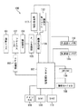
以下、図面を参照しながら本発明の実施形態を説明する。図1は、本発明の実施形態を適用した撮像装置100の構成例を示すブロック図である。
図1において、101はズーム機構を含む撮影レンズである。102は後述する撮像素子上に焦点をあわせるための焦点調節を行うフォーカスレンズである。103はフォーカスレンズ102を駆動するAF処理部である。104はフォーカスレンズ102を介して入射した被写体像を電気信号に変換する光電変換を行い、画像データを取得する撮像素子である。105は撮像素子104の出力ノイズを除去するCDS回路やA/D変換前に行う非線形増幅回路を含むA/D変換部である。
Hereinafter, embodiments of the present invention will be described with reference to the drawings. FIG. 1 is a block diagram illustrating a configuration example of an
In FIG. 1, reference numeral 101 denotes a photographing lens including a zoom mechanism.
106はA/D変換部105の出力信号から被写体の輝度に関する特定周波数帯域の信号成分を抽出する画像処理部である。この画像処理部106を用いて、画像の所定領域における色情報などを取得することが可能である。107は撮影シーケンスなどシステムを制御するシステム制御部(以下CPUと記す)であり、本実施形態の撮像装置全体の動作を制御する。108は顔検出モードをONまたはOFFに切り替える等の設定を行う撮影モードスイッチである。109はシステムに電源を投入するためのメインスイッチ、110はAFやAE等の撮影スタンバイ動作を行うためのスイッチ(以下SW1と記す)である。111はSW1の操作後、撮影を行う撮影スイッチ(以下SW2と記す)である。
An
112は画像処理部106で処理された画像信号を用いて顔検出を行い、検出した一つ又は複数の顔情報(位置・サイズ・信頼度)をCPU107に送る顔検出モジュールである。なお、顔の検出方法は、本発明の主眼点ではないため詳細な説明は省略する。113は画面内の被写体及び背景が動いているかどうかを検出して動体情報をCPU107に送る動体検出部である。具体的には、画像処理部106で処理された画像信号のうち、時系列的に並んだ2枚の画像を比較し、その差分情報から被写体/背景の動体情報(動作量、位置、範囲)を検出する。
A
114は、カメラ自体の角速度を検出してカメラ動き情報をCPU107に送る角速度センサ部である。この角速度センサ部を用いてカメラが縦位置の状態で構えられているのか、横位置の状態で構えられているのかを検出することも可能である。115は、カメラ自体の加速度を検出してカメラの動き情報をCPU107に送る加速度センサ部である。この加速度センサ部を用いて、カメラが撮影レンズ101を上向きに構えられているのか、撮影レンズ101を下向きに構えられているのかを検出することも可能である。116は、高速な内蔵メモリ(例えばランダムアクセスメモリなど、以下DRAMと記す)である。
An angular
(第1の実施形態)
(全体動作)
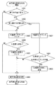
次に、図2のフローチャートを参照しながら、本発明の第1の実施形態による撮像装置での被写体検出時に行われる連続スキャン動作について説明する。ここで、フォーカスレンズ102を移動させながら撮像素子104内のAF枠から得られるAF評価値を記憶していき、当該AF評価値に基づいてフォーカスレンズ102を移動させ焦点調節をする動作をスキャン動作(焦点調節動作)という。ここでいうAF評価値は、フォーカスレンズの合焦状態を示す焦点信号の一例である。
S201では、被写体検出を行う。本実施形態では、被写体を顔とするが、サイズ、位置が検出できれば、被写体は、顔で無くてもよいこととする。被写体検出において、顔は、顔検出モジュール112により検出される。
(First embodiment)
(Overall operation)
Next, the continuous scanning operation performed when the subject is detected by the imaging apparatus according to the first embodiment of the present invention will be described with reference to the flowchart of FIG. Here, the AF evaluation value obtained from the AF frame in the
In S201, subject detection is performed. In this embodiment, the subject is a face, but the subject may not be a face as long as the size and position can be detected. In subject detection, the face is detected by the
次に、S202において、顔サイズが変化しているか否かを検出する。S202で行われる処理の詳細については、図3を用いて後述する。次に、S203において、顔位置が変化しているか否かを検出する。S203で行われる処理の詳細については、図4を用いて後述する。 Next, in S202, it is detected whether or not the face size has changed. Details of the processing performed in S202 will be described later with reference to FIG. Next, in S203, it is detected whether or not the face position has changed. Details of the processing performed in S203 will be described later with reference to FIG.
次に、S204において、S202において検出した顔サイズ変化状態か否かの判断を行う。この判断の結果、顔サイズが変化している状態であれば、S205に進む。また、顔サイズが変化していない場合は、S217に進む。 Next, in S204, it is determined whether or not the face size change state detected in S202. If it is determined that the face size is changing, the process proceeds to S205. If the face size has not changed, the process proceeds to S217.
S217においては、撮影指示判断を行う。この判断の結果、撮影指示がされていた場合は、被写体検出時の連続スキャン動作を終了する。撮影指示がされていない場合は、S201の被写体検出に戻る。 In S217, a shooting instruction is determined. If the result of this determination is that a shooting instruction has been given, the continuous scanning operation at the time of subject detection is terminated. If no shooting instruction has been given, the process returns to S201 subject detection.
S205では、スキャン動作中か否かの判断を行う。この判断の結果、スキャン動作中でなければ、次に、S206において、検出した顔位置が変化しているかの判断を行う。この判断の結果に応じて、フォーカスレンズの合焦状態を検出する際の焦点検出領域を設定する設定動作を変更する。すなわち、顔位置が変化していないと判断された場合は、S207へ進み、顔位置が変化していると判断された場合は、S208へ進む。 In S205, it is determined whether or not a scanning operation is being performed. If the result of this determination is that scanning is not in progress, it is next determined in step S206 whether the detected face position has changed. In accordance with the result of this determination, the setting operation for setting the focus detection area when detecting the focus state of the focus lens is changed. That is, if it is determined that the face position has not changed, the process proceeds to S207, and if it is determined that the face position has changed, the process proceeds to S208.
S207では、フォーカスレンズの移動範囲である通常スキャン範囲を設定する。本実施形態での、通常スキャン範囲とは、現在のフォーカスレンズ位置を中心として、近側、遠側、それぞれに、ピントが合っているとみなせる範囲である焦点深度の5倍分の領域とする。一方、S208では、狭いスキャン範囲を設定し、S209に進む。なお、狭いスキャン範囲とは、通常のスキャン範囲よりも狭い領域のことである。本実施形態では、通常スキャン範囲の半分の領域とする。 In step S207, a normal scan range that is a movement range of the focus lens is set. In the present embodiment, the normal scan range is an area corresponding to five times the depth of focus, which is a range that can be considered to be in focus on the near side and the far side with the current focus lens position as the center. . On the other hand, in S208, a narrow scan range is set, and the process proceeds to S209. Note that the narrow scan range is a region narrower than the normal scan range. In the present embodiment, the area is a half of the normal scan range.
S208において狭いスキャン範囲を設定することにより、AF枠が被写体から外れた場合、スキャンした結果のAF評価値のピーク位置が背景側にずれたとしても、最大、スキャン範囲の半分となるので、大きくずれることを防ぐことができる。また、本実施形態では、スキャン開始位置とは、スキャン範囲の遠端、スキャン終了位置とは、スキャン範囲の近端とする。 By setting a narrow scan range in S208, if the AF frame deviates from the subject, even if the peak position of the AF evaluation value as a result of scanning is shifted to the background side, the maximum is half of the scan range. It can be prevented from shifting. In this embodiment, the scan start position is the far end of the scan range, and the scan end position is the near end of the scan range.
S207またはS208の処理を終了したら、S209に進む。S209ではフォーカスレンズ102を移動させる。次に、S210において、移動したフォーカスレンズ位置でのAF評価値を取得する。次に、S211において、フォーカスレンズがスキャン終了位置まで移動したか否かを判断を行う。
When the process of S207 or S208 is completed, the process proceeds to S209. In step S209, the
S211の判断の結果、スキャン終了位置まで移動していない場合は、S217において、撮影指示判断を行う。一方、スキャン終了位置まで移動している場合は、S212において、AF評価値のピーク位置が検出されたかの判断を行う。この判断の結果、ピーク位置が検出されている場合は、S213において、フォーカスレンズ位置をピーク位置へ移動し、その後、S217において、撮影指示判断を行う。 If the result of determination in S211 is that it has not moved to the scan end position, shooting instruction determination is performed in S217. On the other hand, if it has moved to the scan end position, it is determined in S212 whether the peak position of the AF evaluation value has been detected. If the peak position is detected as a result of this determination, the focus lens position is moved to the peak position in S213, and then a shooting instruction is determined in S217.
また、S212の判断の結果、ピーク位置が無い場合は、次にS214において、AF評価値がスキャン開始位置、もしくはスキャン終了位置において最大になり、登り止まっているかの判断を行う。この判断の結果、登り止まっていれば、S215において、登り止まっている端にフォーカスレンズ位置へ移動し、その後、S217において撮影指示判断を行う。また、S214の判断の結果、登り止まっていない場合は、S216において、スキャン範囲中心位置へ移動し、その後、S217において撮影指示判断を行う。 If there is no peak position as a result of the determination in S212, then in S214, it is determined whether the AF evaluation value is maximized at the scan start position or the scan end position, and the climb is stopped. If the result of this determination is that climbing has stopped, the focus lens position is moved to the end where climbing has stopped in S215, and then a shooting instruction is determined in S217. As a result of the determination in S214, if the climb has not stopped, the camera moves to the center position of the scan range in S216, and then the imaging instruction is determined in S217.
このようにして、連続してスキャン動作を行うことで、距離方向に動きのある被写体に対し、ピントを合わせ続けることができる。また、位置変化状態であると判断した場合は、スキャン範囲を狭くすることにより、背景抜けの影響を抑えることができる。 By continuously performing the scanning operation in this manner, it is possible to continue focusing on the subject moving in the distance direction. If it is determined that the position is changed, the influence of background loss can be suppressed by narrowing the scan range.
(被写体サイズ変化検出)
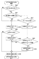
次に、図3のフローチャートを参照しながら、本実施形態の撮像装置での被写体サイズ変化検出について説明する。
S301では、検出した被写体のサイズが変化したかを判断する。サイズ変化判断は、後述するS306においてDRAM116に、フォーカスレンズの位置と関連づけて記憶していた被写体サイズと、今回取得した被写体サイズに差があるか否かに基いて判断している。
(Subject size change detection)
Next, the subject size change detection in the imaging apparatus of the present embodiment will be described with reference to the flowchart of FIG.
In S301, it is determined whether the size of the detected subject has changed. The size change determination is made based on whether or not there is a difference between the subject size stored in the
S301の判断の結果、変化していると判断した場合はS302に進み、その差分が所定量以内であるか否かを判断する。この判断の結果、所定量以上変化している場合は、今回検出した被写体が前回検出した被写体と異なると考えられる。
S301の判断の結果、変化していないと判断した場合は、S303においてサイズ変化カウンタを0にする。その後、S304において、サイズ変化状態であるかを判断する。これは、DRAM116に、サイズ変化状態が設定されているかを読み出すことで判断する。ここで、サイズ変化カウンタとは、連続して被写体サイズが変化したかを判断するために、DRAM116に記憶される値である。
As a result of the determination in S301, if it is determined that it has changed, the process proceeds to S302, and it is determined whether or not the difference is within a predetermined amount. As a result of this determination, if the amount has changed by a predetermined amount or more, it is considered that the subject detected this time is different from the subject detected last time.
As a result of the determination in S301, if it is determined that there is no change, the size change counter is set to 0 in S303. Thereafter, in S304, it is determined whether the size is changed. This is determined by reading out whether the size change state is set in the
一方、S302の判断の結果、被写体サイズ変化量が所定量以内でなければ、被写体が異なっていると考えられるので、S303に進んでサイズ変化カウンタを0にする。次に、S304において、前述したように、サイズ変化状態であるか否かを判断する。 On the other hand, as a result of the determination in S302, if the subject size change amount is not within the predetermined amount, it is considered that the subject is different, so the process proceeds to S303 and the size change counter is set to zero. Next, in S304, as described above, it is determined whether or not the size is changed.
S304の判断の結果、サイズ変化状態である場合は、S305において、DRAM116に記憶されているサイズ変化状態をクリアし、次に、S306において、被写体サイズをDRAM116に記憶し、被写体サイズ変化検出を終了する。一方、S304の判断の結果、サイズ変化状態でない場合は、S306に直接進み、被写体サイズをDRAM116に記憶し、被写体サイズ変化検出を終了する。
If the result of determination in S304 is that there is a size change state, the size change state stored in
また、S302の判断の結果、被写体サイズ変化量が所定量以内であれば、S307に進んでサイズ変化カウンタを「+1」する。次に、S308において、サイズ変化カウンタと、DRAM116に記憶されている値であるサイズ変化カウンタ閾値と比較する。サイズ変化カウンタ閾値とは、その値以上連続して被写体のサイズが変化していれば、被写体が奥行き方向に動いていると判断する閾値のことである。閾値よりも、サイズ変化カウンタが少ない場合は、S306において、被写体サイズを記憶した後、被写体サイズ変化検出を終了する。また、サイズ変化カウンタ閾値よりも、サイズ変化カウンタが多い場合はS309に進んでDRAM116に、サイズ変化状態であることを記憶する。次に、S306において、被写体サイズを記憶した後、被写体サイズ変化検出を終了する。
If it is determined in step S302 that the subject size change amount is within the predetermined amount, the process advances to step S307 to increment the size change counter by “+1”. In step S308, the size change counter is compared with a size change counter threshold value that is a value stored in the DRAM. The size change counter threshold value is a threshold value that determines that the subject is moving in the depth direction if the size of the subject has continuously changed beyond that value. If the size change counter is smaller than the threshold value, the subject size change detection is terminated after storing the subject size in S306. If there are more size change counters than the size change counter threshold value, the process advances to S309 to store the size change state in the
被写体サイズは、被写体が顔の場合は、顔検出モジュール112において検出される。被写体が顔でない場合は、画像処理部106において取得された色情報の変化から検出する。例えば、被写体領域における同色領域の変化や、被写体領域における動体検出部113において検出される輝度差分情報や、連続スキャンした結果のピーク位置における合焦距離の変化などから検出することができる。
The subject size is detected by the
(被写体位置変化検出)
次に、図4のフローチャートを参照しながら、本実施形態の撮像装置での被写体位置変化検出について説明する。
S401では、検出した被写体の位置が変化したかを判断する。この位置変化判断は、S406においてDRAM116に記憶していた被写体位置と、今回取得した被写体位置に差があるかに基いて判断している。
(Subject position change detection)
Next, subject position change detection in the imaging apparatus of the present embodiment will be described with reference to the flowchart of FIG.
In S401, it is determined whether the position of the detected subject has changed. This position change determination is made based on whether there is a difference between the subject position stored in the
この判断の結果、変化していると判断した場合は、次に、ステップS402にて、その差分が所定量以内であるかを判断する。この判断において、所定量以上変化している場合は、今回検出した被写体が前回検出した被写体と異なると考えられる。 As a result of this determination, if it is determined that it has changed, it is next determined in step S402 whether the difference is within a predetermined amount. In this determination, if the amount has changed by a predetermined amount or more, it is considered that the subject detected this time is different from the subject detected last time.
S401の判断の結果、被写体位置が変化していないと判断した場合は、S403に進んで位置変化カウンタを0にした後、ステップS404にて、位置変化状態であるかを判断する。これは、DRAM116に、位置変化状態が設定されているかを読みだすことで判断する。なお、位置変化カウンタとは、連続して被写体位置が変化したかを判断する為に、DRAM116に記憶される値である。
As a result of the determination in S401, if it is determined that the subject position has not changed, the process proceeds to S403 to set the position change counter to 0, and then in step S404, it is determined whether or not the position is changed. This is determined by reading out whether the position change state is set in the
S402の判断の結果、被写体位置変化量が所定量以内でなければ、被写体が異なっていると考えられるので、次のステップS403にて、位置変化カウンタを0にする。次に、ステップS404にて、位置変化状態であるか否かを判断する。この判断の結果、位置変化状態である場合は、S405において、DRAM116に記憶されている位置変化状態をクリアする。次に、S406において、被写体位置をDRAM116に記憶し、被写体位置変化検出を終了する。また、S404の判断の結果、位置変化状態でない場合は、S406に直接進み、前述した処理を実行し、被写体位置変化検出を終了する。
As a result of the determination in S402, if the subject position change amount is not within the predetermined amount, it is considered that the subject is different, so the position change counter is set to 0 in the next step S403. Next, in step S404, it is determined whether or not the position is changed. If the result of this determination is that there is a position change state, the position change state stored in the
一方、S402の判断の結果、被写体位置変化量が所定量以内であれば、S407に進んで位置変化カウンタを「+1」する。次に、S408において、位置変化カウンタと、DRAM116に記憶されている値である位置変化カウンタ閾値と比較する。位置変化カウンタ閾値とは、その値以上連続して被写体の位置が変化していれば、被写体が上下左右方向に動いていると判断する閾値のことである。この判断の結果、閾値よりも、位置変化カウンタが少ない場合は、S406において、被写体位置を記憶した後、被写体位置変化検出を終了する。
On the other hand, as a result of the determination in S402, if the subject position change amount is within the predetermined amount, the process proceeds to S407 and the position change counter is incremented by "+1". In step S <b> 408, the position change counter is compared with a position change counter threshold value that is a value stored in the
S408の判断の結果、位置変化カウンタ閾値よりも、位置変化カウンタが多い場合は、次に、S409において、DRAM116に、位置変化状態であることを記憶する。次に、S406に進み、前述した処理を実行後、被写体位置変化検出を終了する。なお、被写体位置は、被写体が顔の場合は、顔検出モジュール112において、検出される。被写体が顔でない場合は、被写体領域における動体検出部113において検出される輝度差分情報などから検出することができる。
If the result of determination in S408 is that there are more position change counters than the position change counter threshold value, next, in S409, it is stored in the
(第2の実施形態)
(全体動作)
次に、図5のフローチャートを参照しながら、本発明の第2の実施形態による撮像装置での被写体検出時の連続スキャン動作について説明する。
S501では、被写体検出を行う。本実施形態でも、被写体を顔とする。顔は、顔検出モジュール112により検出される。
(Second Embodiment)
(Overall operation)
Next, a continuous scanning operation at the time of subject detection in the imaging apparatus according to the second embodiment of the present invention will be described with reference to the flowchart of FIG.
In S501, subject detection is performed. Also in this embodiment, the subject is a face. The face is detected by the
次に、S502において、被写体サイズの変化を検出する。S502において行われる処理の詳細は、図3を用いて前述した通りである。次に、S503において、被写体位置の変化を検出する。S503で行われる処理の詳細については、図6を用いて後述する。 Next, in S502, a change in subject size is detected. Details of the processing performed in S502 are as described above with reference to FIG. Next, in S503, a change in subject position is detected. Details of the processing performed in S503 will be described later with reference to FIG.
次に、S504において、S502において検出した顔サイズが変化状態か否かを判断する。この判断の結果、顔サイズが変化している状態であると判断された場合は、S505に進む。また、顔サイズが変化している状態で無いと判断された場合は、S516に進んで撮影指示の有無を判断する。この判断の結果、撮影指示がされていた場合は、被写体検出時の連続スキャン動作を終了する。また、撮影指示がされていない場合は、S501の被写体検出に戻る。 Next, in S504, it is determined whether or not the face size detected in S502 is changed. As a result of this determination, if it is determined that the face size is changing, the process proceeds to S505. If it is determined that the face size is not changing, the process proceeds to S516 to determine whether there is a shooting instruction. If the result of this determination is that a shooting instruction has been given, the continuous scanning operation at the time of subject detection is terminated. If no shooting instruction is given, the process returns to the subject detection in S501.
S505では、スキャン動作中か否かの判断を行う。この判断の結果、スキャン動作中でなければ、次に、S506において、スキャン範囲の設定を行い、その後、S507に進む。また、スキャン動作中であれば、S507に進む。S506において行われるスキャン範囲の設定は、現在のフォーカスレンズ位置を中心として、近側、遠側、それぞれに、ピントが合っているとみなせる範囲である焦点深度の5倍分の領域を設定する。また、本実施形態では、スキャン開始位置とは、スキャン範囲の遠端、スキャン終了位置とは、スキャン範囲の近端とする。 In S505, it is determined whether or not a scanning operation is being performed. If the result of this determination is that scanning is not in progress, then in S506, a scan range is set, and then processing proceeds to S507. If the scan operation is being performed, the process proceeds to S507. In the setting of the scan range performed in S506, an area corresponding to five times the focal depth, which is a range that can be regarded as being in focus, is set on each of the near side and the far side with the current focus lens position as the center. In this embodiment, the scan start position is the far end of the scan range, and the scan end position is the near end of the scan range.
次に、S507では、顔位置が変化している状態か否かの判断を行う。この判断の結果、顔位置が変化している状態だと判断された場合は、S515に進んでスキャン範囲の中心位置、すなわち、スキャン範囲の中心位置へ移動し、その後、S516の撮影指示判断を行う。一方、S507の判断の結果、顔位置が変化している状態で無いと判断された場合は、S508においてフォーカスレンズを移動させる。次に、S509において、移動したフォーカスレンズ位置でのAF評価値を取得する。 Next, in S507, it is determined whether or not the face position is changing. As a result of this determination, if it is determined that the face position has changed, the process proceeds to S515 to move to the center position of the scan range, that is, the center position of the scan range, and then the imaging instruction determination in S516 is performed. Do. On the other hand, if it is determined in S507 that the face position is not changed, the focus lens is moved in S508. In step S509, an AF evaluation value at the moved focus lens position is acquired.
次に、S510において、フォーカスレンズ102がスキャン終了位置まで移動したかの判断を行う。この判断の結果、スキャン終了位置まで移動していない場合は、S516に進んで撮影指示判断を行う。また、スキャン終了位置まで移動している場合は、次にS511において、AF評価値のピーク位置が検出されたか判断する。この判断の結果、ピーク位置が検出されている場合は、S512において、フォーカスレンズ位置をピーク位置へ移動し、その後、S516において撮影指示判断を行う。
Next, in S510, it is determined whether the
S511の判断の結果、ピーク位置が無い場合は、次にS513において、AF評価値が、スキャン開始位置、もしくはスキャン終了位置において最大になり、登り止まっているか判断する。この判断の結果、登り止まっていれば、S514に進んで登り止まっている端にフォーカスレンズ位置へ移動し、その後、S516において撮影指示判断を行う。また、S513の判断の結果、登り止まっていない場合は、S515に進んでスキャン範囲中心位置へ移動し、その後、S516において撮影指示判断を行う。 If there is no peak position as a result of the determination in S511, then in S513, it is determined whether the AF evaluation value is maximized at the scan start position or the scan end position, and has stopped climbing. As a result of this determination, if the climb has stopped, the process proceeds to S514 to move to the focus lens position at the end where the climb has stopped, and then a shooting instruction is determined in S516. As a result of the determination in S513, if the climb has not stopped, the process proceeds to S515 to move to the center position of the scan range, and then a shooting instruction is determined in S516.
本実施形態においては、このようにして、連続してスキャン動作を行うことで、距離方向に動きのある被写体に対し、ピントを合わせ続けることができる。また、位置変化状態であると判断した場合は、スキャン範囲の中心位置からフォーカスレンズを動かさないことにより、被写体距離に変化の無い場合にスキャンを行うことを無くすことができ、背景抜けを防ぐことができる。 In the present embodiment, by continuously performing the scanning operation in this manner, it is possible to continuously focus on a subject that moves in the distance direction. In addition, if it is determined that the position has changed, the focus lens is not moved from the center position of the scan range, so that it is possible to eliminate scanning when the subject distance does not change, thus preventing background loss. Can do.
(被写体位置変化検出)
次に、図6のフローチャートを参照しながら、本実施形態の撮像装置での被写体位置変化検出動作について説明する。
S601では、検出した被写体の位置が変化したかを判断する。位置変化判断は、S406においてDRAM116に記憶していた被写体位置と、今回取得した被写体位置に差があるかに基いて判断している。
(Subject position change detection)
Next, a subject position change detection operation in the imaging apparatus of the present embodiment will be described with reference to the flowchart of FIG.
In step S601, it is determined whether the position of the detected subject has changed. The position change determination is made based on whether there is a difference between the subject position stored in the
S601の判断の結果、被写体位置が変化していると判断した場合は、S602において、その差分が所定量以内であるか判断する。この判断の結果、所定量以上変化している場合は、今回検出した被写体が前回検出した被写体と異なると考えられる。 If it is determined that the subject position has changed as a result of the determination in S601, it is determined in S602 whether the difference is within a predetermined amount. As a result of this determination, if the amount has changed by a predetermined amount or more, it is considered that the subject detected this time is different from the subject detected last time.
S601の判断の結果、被写体位置が変化していないと判断した場合はS403に進む。また、S602の判断の結果、被写体位置変化量が所定量以内でなければ、被写体が異なっていると考えられるのでS403に進む。S403〜S406で行われる処理は、前述した図4で行われる処理と同じであるので、詳細な説明を省略する。 As a result of the determination in S601, if it is determined that the subject position has not changed, the process proceeds to S403. If the subject position change amount is not within the predetermined amount as a result of the determination in S602, it is considered that the subject is different, and the process proceeds to S403. Since the processing performed in S403 to S406 is the same as the processing performed in FIG. 4 described above, detailed description thereof is omitted.
一方、S602の判断の結果、被写体位置変化量が所定量以内であれば、S607に進んでサイズ変化状態であるかを判断する。これは、DRAM116に、サイズ変化状態が設定されているかを読み出すことで判断する。この判断の結果、サイズ変化状態であれば、被写体の位置が変化していても、位置変化状態とせず、また位置変化状態であれば、その状態を解除する。このようにすることで位置変化状態により、スキャンが停止されていても、被写体のサイズが変化したことにより、スキャンを再開することができる。
On the other hand, as a result of the determination in S602, if the subject position change amount is within the predetermined amount, the process proceeds to S607 and it is determined whether or not the size is changed. This is determined by reading out whether the size change state is set in the
S607の判断の結果、サイズ変化状態であると判断した場合はS403に進む。また、サイズ変化状態で無いと判断した場合はS407に進む。S407〜S409で行われる処理は、前述した図4で行われる処理と同じであるので、詳細な説明を省略する。 As a result of the determination in S607, if it is determined that the size is changed, the process proceeds to S403. If it is determined that the size is not changed, the process proceeds to S407. Since the processing performed in S407 to S409 is the same as the processing performed in FIG. 4 described above, detailed description thereof is omitted.
(その他の実施形態)
また、本発明は、以下の処理を実行することによっても実現される。即ち、前述した実施形態の機能を実現するソフトウェア(コンピュータプログラム)を、ネットワーク又は各種のコンピュータ読み取り可能な記憶媒体を介してシステム或いは装置に供給する。そして、そのシステム或いは装置のコンピュータ(またはCPUやMPU等)がプログラムを読み出して実行する処理である。
(Other embodiments)
The present invention can also be realized by executing the following processing. That is, software (computer program) that implements the functions of the above-described embodiments is supplied to a system or apparatus via a network or various computer-readable storage media. Then, the computer (or CPU, MPU, etc.) of the system or apparatus reads out and executes the program.
101 撮影レンズ、102 フォーカスレンズ、103 AF処理部、104 撮像素子、105 A/D変換部、106 画像処理部、107 システム制御部(CPU)、108 撮影モードスイッチ、109 メインスイッチ、110 撮影スタンバイスイッチ(SW1)、111 撮影スイッチ(SW2)、 112 顔検出モジュール、113 動体検出部、114 角速度センサ部、115 加速度センサ部、116 DRAM DESCRIPTION OF SYMBOLS 101 Shooting lens, 102 Focus lens, 103 AF process part, 104 Image sensor, 105 A / D conversion part, 106 Image processing part, 107 System control part (CPU), 108 Shooting mode switch, 109 Main switch, 110 Shooting standby switch (SW1), 111 shooting switch (SW2), 112 face detection module, 113 moving object detection unit, 114 angular velocity sensor unit, 115 acceleration sensor unit, 116 DRAM
Claims (4)
前記焦点調節は、前記被写体に追従しながら前記フォーカスレンズのスキャン範囲の中心位置を移動させており、前記焦点調節のフォーカスレンズのスキャン範囲は、前記フォーカスレンズの移動範囲よりも狭く、
前記制御手段は、前記検出した被写体のサイズが変化しない場合、前記検出した被写体の位置が変化しても変化しなくても、前記焦点調節を行わず、前記検出した被写体のサイズが変化した場合、前記検出した被写体の位置が変化しても変化しなくても、前記フォーカスレンズを移動させながら焦点信号を取得する際のフォーカスレンズを移動させており、前記検出した被写体のサイズが変化し前記検出した被写体の位置が変化した場合、前記検出した被写体のサイズが変化し前記検出した被写体の位置が変化しない場合に比べて前記フォーカスレンズを移動させながら焦点信号を取得する際のフォーカスレンズの移動範囲を狭めるように制御することを特徴とする撮像装置。 An imaging means for photoelectrically converting a subject image incident through a focus lens to obtain image data; a detection means for detecting the size of the subject and the position of the subject from the image data obtained by the imaging means; and the focus A control means for acquiring a focus signal indicating a focus state of the focus lens based on the image data while moving the lens continuously, and performing focus adjustment by moving the focus lens based on the focus signal; And the control means performs the step of determining the change in the position of the subject after performing the step of determining the change in the size of the subject,
The focus adjustment moves the center position of the scan range of the focus lens while following the subject, and the scan range of the focus lens of the focus adjustment is narrower than the movement range of the focus lens,
When the size of the detected subject does not change, the control means does not perform the focus adjustment even if the position of the detected subject changes or does not change, and the size of the detected subject changes Even if the position of the detected subject changes or does not change, the focus lens for obtaining the focus signal is moved while moving the focus lens, and the size of the detected subject changes and the When the position of the detected subject changes, the focus lens moves when acquiring the focus signal while moving the focus lens compared to the case where the size of the detected subject changes and the position of the detected subject does not change. An imaging device that is controlled to narrow a range .
前記焦点調節は、前記被写体に追従しながら前記フォーカスレンズのスキャン範囲の中心位置を移動させており、前記焦点調節のフォーカスレンズのスキャン範囲は、前記フォーカスレンズの移動範囲よりも狭く、
前記制御工程は、前記検出した被写体のサイズが変化しない場合、前記検出した被写体の位置が変化しても変化しなくても、前記焦点調節を行わず、前記検出した被写体のサイズが変化した場合、前記検出した被写体の位置が変化しても変化しなくても、前記フォーカスレンズを移動させながら焦点信号を取得する際のフォーカスレンズを移動させており、前記検出した被写体のサイズが変化し前記検出した被写体の位置が変化した場合、前記検出した被写体のサイズが変化し前記検出した被写体の位置が変化しない場合に比べて前記フォーカスレンズを移動させながら焦点信号を取得する際のフォーカスレンズの移動範囲を狭めるように制御していることを特徴とする撮像装置の制御方法。 An imaging step for photoelectrically converting a subject image incident through a focus lens to obtain image data, a detection step for detecting the size of the subject and the position of the subject from the image data obtained by the imaging step, and the focus A control step of acquiring a focus signal indicating a focus state of the focus lens based on the image data while moving the lens continuously, and performing focus adjustment by moving the focus lens based on the focus signal; And the control step includes a step of determining a change in the position of the subject and then a step of determining a change in the position of the subject.
The focus adjustment moves the center position of the scan range of the focus lens while following the subject, and the scan range of the focus lens of the focus adjustment is narrower than the movement range of the focus lens,
In the control step, when the size of the detected subject does not change, even when the position of the detected subject changes or does not change, the focus adjustment is not performed, and the size of the detected subject changes. Even if the position of the detected subject changes or does not change, the focus lens for obtaining the focus signal is moved while moving the focus lens, and the size of the detected subject changes and the When the position of the detected subject changes, the focus lens moves when acquiring the focus signal while moving the focus lens compared to the case where the size of the detected subject changes and the position of the detected subject does not change. A control method for an imaging apparatus, wherein control is performed to narrow a range .
Priority Applications (3)
| Application Number | Priority Date | Filing Date | Title |
|---|---|---|---|
| JP2009189154A JP5213813B2 (en) | 2009-08-18 | 2009-08-18 | IMAGING DEVICE AND IMAGING DEVICE CONTROL METHOD |
| US12/854,813 US8964101B2 (en) | 2009-08-18 | 2010-08-11 | Imaging apparatus and method for controlling the same |
| CN2010102583641A CN101995733B (en) | 2009-08-18 | 2010-08-17 | Imaging apparatus and control method thereof |
Applications Claiming Priority (1)
| Application Number | Priority Date | Filing Date | Title |
|---|---|---|---|
| JP2009189154A JP5213813B2 (en) | 2009-08-18 | 2009-08-18 | IMAGING DEVICE AND IMAGING DEVICE CONTROL METHOD |
Publications (3)
| Publication Number | Publication Date |
|---|---|
| JP2011039433A JP2011039433A (en) | 2011-02-24 |
| JP2011039433A5 JP2011039433A5 (en) | 2012-09-20 |
| JP5213813B2 true JP5213813B2 (en) | 2013-06-19 |
Family
ID=43605069
Family Applications (1)
| Application Number | Title | Priority Date | Filing Date |
|---|---|---|---|
| JP2009189154A Expired - Fee Related JP5213813B2 (en) | 2009-08-18 | 2009-08-18 | IMAGING DEVICE AND IMAGING DEVICE CONTROL METHOD |
Country Status (3)
| Country | Link |
|---|---|
| US (1) | US8964101B2 (en) |
| JP (1) | JP5213813B2 (en) |
| CN (1) | CN101995733B (en) |
Cited By (1)
| Publication number | Priority date | Publication date | Assignee | Title |
|---|---|---|---|---|
| JP7284295B2 (en) | 2020-01-14 | 2023-05-30 | 株式会社日本触媒 | Method for producing acrylic acid |
Families Citing this family (9)
| Publication number | Priority date | Publication date | Assignee | Title |
|---|---|---|---|---|
| JP5178797B2 (en) * | 2010-09-13 | 2013-04-10 | キヤノン株式会社 | Display control apparatus and display control method |
| JP5882726B2 (en) * | 2011-12-27 | 2016-03-09 | キヤノン株式会社 | Focus adjustment device |
| JP5894440B2 (en) * | 2012-01-05 | 2016-03-30 | キヤノン株式会社 | Focus adjustment device |
| JP6397281B2 (en) * | 2013-10-23 | 2018-09-26 | キヤノン株式会社 | Imaging apparatus, control method thereof, and program |
| US9742980B2 (en) * | 2013-11-01 | 2017-08-22 | Canon Kabushiki Kaisha | Focus control apparatus and control method therefor |
| JP6234261B2 (en) * | 2014-02-10 | 2017-11-22 | オリンパス株式会社 | Focus adjustment apparatus and control method |
| US9686463B2 (en) * | 2015-03-10 | 2017-06-20 | Qualcomm Incorporated | Systems and methods for continuous auto focus (CAF) |
| JP6525813B2 (en) * | 2015-08-21 | 2019-06-05 | キヤノン株式会社 | Imaging device, control method, program, and storage medium |
| WO2018168357A1 (en) | 2017-03-15 | 2018-09-20 | 富士フイルム株式会社 | Image-capture device, image-capture method, and image-capture program |
Family Cites Families (14)
| Publication number | Priority date | Publication date | Assignee | Title |
|---|---|---|---|---|
| JPH09197256A (en) * | 1996-01-17 | 1997-07-31 | Olympus Optical Co Ltd | Moving body predicting camera |
| US7561790B2 (en) * | 2004-12-28 | 2009-07-14 | Fujinon Corporation | Auto focus system |
| JP4674471B2 (en) * | 2005-01-18 | 2011-04-20 | 株式会社ニコン | Digital camera |
| EP1684503B1 (en) * | 2005-01-25 | 2016-01-13 | Canon Kabushiki Kaisha | Camera and autofocus control method therefor |
| JP4310309B2 (en) * | 2005-12-27 | 2009-08-05 | キヤノン株式会社 | Optical device and method for controlling optical device |
| US7634185B2 (en) * | 2006-02-02 | 2009-12-15 | Canon Kabushiki Kaisha | Focusing device, image pickup apparatus, and control method |
| JP2007206433A (en) * | 2006-02-02 | 2007-08-16 | Canon Inc | Focusing apparatus, imaging apparatus, and control method |
| JP4697606B2 (en) * | 2007-01-24 | 2011-06-08 | 富士フイルム株式会社 | Imaging apparatus and focus control method |
| JP2009031760A (en) | 2007-07-04 | 2009-02-12 | Sanyo Electric Co Ltd | Imaging apparatus and automatic focus control method |
| US20090009651A1 (en) * | 2007-07-04 | 2009-01-08 | Sanyo Electric Co., Ltd. | Imaging Apparatus And Automatic Focus Control Method |
| JP2009055160A (en) * | 2007-08-24 | 2009-03-12 | Sony Corp | Imaging apparatus and imaging method |
| JP5004726B2 (en) * | 2007-09-05 | 2012-08-22 | キヤノン株式会社 | Imaging apparatus, lens unit, and control method |
| JP5048468B2 (en) * | 2007-11-28 | 2012-10-17 | 富士フイルム株式会社 | Imaging apparatus and imaging method thereof |
| JP4535173B2 (en) * | 2008-06-26 | 2010-09-01 | ソニー株式会社 | Imaging apparatus, focus control method, and program |
-
2009
- 2009-08-18 JP JP2009189154A patent/JP5213813B2/en not_active Expired - Fee Related
-
2010
- 2010-08-11 US US12/854,813 patent/US8964101B2/en not_active Expired - Fee Related
- 2010-08-17 CN CN2010102583641A patent/CN101995733B/en not_active Expired - Fee Related
Cited By (1)
| Publication number | Priority date | Publication date | Assignee | Title |
|---|---|---|---|---|
| JP7284295B2 (en) | 2020-01-14 | 2023-05-30 | 株式会社日本触媒 | Method for producing acrylic acid |
Also Published As
| Publication number | Publication date |
|---|---|
| US20110043681A1 (en) | 2011-02-24 |
| CN101995733A (en) | 2011-03-30 |
| CN101995733B (en) | 2013-11-27 |
| US8964101B2 (en) | 2015-02-24 |
| JP2011039433A (en) | 2011-02-24 |
Similar Documents
| Publication | Publication Date | Title |
|---|---|---|
| JP5213813B2 (en) | IMAGING DEVICE AND IMAGING DEVICE CONTROL METHOD | |
| JP5789098B2 (en) | Focus detection apparatus and control method thereof | |
| JP2005241805A (en) | Automatic focusing system and its program | |
| JP2010072045A (en) | Imaging apparatus and control method | |
| JP2012058587A (en) | Autofocus device, image pickup device, focus control method, and program | |
| JP2020022012A (en) | Imaging device and control method thereof | |
| JP2010097211A (en) | Imaging apparatus and imaging position setting method | |
| JP2015106116A (en) | Imaging apparatus | |
| JP6234016B2 (en) | Focus adjustment device, imaging device, and control method thereof | |
| JP5744501B2 (en) | Focus adjustment apparatus, control method thereof, and program | |
| JP6501536B2 (en) | Imaging device, control method therefor, program, storage medium | |
| JP2010008855A (en) | Image pickup device | |
| JP6624789B2 (en) | Focus control device, control method thereof, control program, and imaging device | |
| JP6351255B2 (en) | Imaging apparatus, imaging method, program, and storage medium | |
| JP4769667B2 (en) | Imaging device | |
| JP2006330394A (en) | Autofocus device | |
| JP2006157604A (en) | Camera apparatus and automatic photographing control program | |
| JP6257186B2 (en) | Imaging apparatus, imaging method, and program | |
| JP6164978B2 (en) | FOCUS ADJUSTMENT DEVICE, ITS CONTROL METHOD, CONTROL PROGRAM, AND IMAGING DEVICE | |
| JP2020088810A (en) | Imaging apparatus and control method of imaging apparatus | |
| JP5904781B2 (en) | Automatic focus adjustment device, control method thereof, and program | |
| JP2006215379A (en) | Imaging apparatus and imaging method | |
| JP5697650B2 (en) | Imaging apparatus and control method thereof | |
| JP2019086580A (en) | Focus adjustment device, focus adjustment method and imaging apparatus | |
| JP4574726B2 (en) | Imaging apparatus and automatic focusing control method |
Legal Events
| Date | Code | Title | Description |
|---|---|---|---|
| A521 | Request for written amendment filed |
Free format text: JAPANESE INTERMEDIATE CODE: A523 Effective date: 20120803 |
|
| A621 | Written request for application examination |
Free format text: JAPANESE INTERMEDIATE CODE: A621 Effective date: 20120803 |
|
| A871 | Explanation of circumstances concerning accelerated examination |
Free format text: JAPANESE INTERMEDIATE CODE: A871 Effective date: 20120803 |
|
| A975 | Report on accelerated examination |
Free format text: JAPANESE INTERMEDIATE CODE: A971005 Effective date: 20120824 |
|
| A131 | Notification of reasons for refusal |
Free format text: JAPANESE INTERMEDIATE CODE: A131 Effective date: 20120911 |
|
| A521 | Request for written amendment filed |
Free format text: JAPANESE INTERMEDIATE CODE: A523 Effective date: 20121112 |
|
| A131 | Notification of reasons for refusal |
Free format text: JAPANESE INTERMEDIATE CODE: A131 Effective date: 20121211 |
|
| A521 | Request for written amendment filed |
Free format text: JAPANESE INTERMEDIATE CODE: A523 Effective date: 20121225 |
|
| TRDD | Decision of grant or rejection written | ||
| A01 | Written decision to grant a patent or to grant a registration (utility model) |
Free format text: JAPANESE INTERMEDIATE CODE: A01 Effective date: 20130129 |
|
| A61 | First payment of annual fees (during grant procedure) |
Free format text: JAPANESE INTERMEDIATE CODE: A61 Effective date: 20130226 |
|
| R151 | Written notification of patent or utility model registration |
Ref document number: 5213813 Country of ref document: JP Free format text: JAPANESE INTERMEDIATE CODE: R151 |
|
| FPAY | Renewal fee payment (event date is renewal date of database) |
Free format text: PAYMENT UNTIL: 20160308 Year of fee payment: 3 |
|
| LAPS | Cancellation because of no payment of annual fees |