JP5405015B2 - Cooling system - Google Patents

Cooling system Download PDF

Info

Publication number
JP5405015B2
JP5405015B2 JP2007327771A JP2007327771A JP5405015B2 JP 5405015 B2 JP5405015 B2 JP 5405015B2 JP 2007327771 A JP2007327771 A JP 2007327771A JP 2007327771 A JP2007327771 A JP 2007327771A JP 5405015 B2 JP5405015 B2 JP 5405015B2
Authority
JP
Japan
Prior art keywords
refrigerant
path
pipe
cooling device
heat exchange
Prior art date
Legal status (The legal status is an assumption and is not a legal conclusion. Google has not performed a legal analysis and makes no representation as to the accuracy of the status listed.)
Expired - Fee Related
Application number
JP2007327771A
Other languages
Japanese (ja)
Other versions
JP2009150588A (en
Inventor
和芳 関
Current Assignee (The listed assignees may be inaccurate. Google has not performed a legal analysis and makes no representation or warranty as to the accuracy of the list.)
Hoshizaki Electric Co Ltd
Original Assignee
Hoshizaki Electric Co Ltd
Priority date (The priority date is an assumption and is not a legal conclusion. Google has not performed a legal analysis and makes no representation as to the accuracy of the date listed.)
Filing date
Publication date
Priority to JP2007327771A priority Critical patent/JP5405015B2/en
Application filed by Hoshizaki Electric Co Ltd filed Critical Hoshizaki Electric Co Ltd
Priority to AU2008336946A priority patent/AU2008336946B2/en
Priority to PCT/JP2008/069049 priority patent/WO2009078218A1/en
Priority to US12/735,130 priority patent/US20110232873A1/en
Priority to EP08862712.0A priority patent/EP2233861B1/en
Priority to CN2008801217507A priority patent/CN101903712A/en
Priority to TW097142327A priority patent/TWI420063B/en
Publication of JP2009150588A publication Critical patent/JP2009150588A/en
Application granted granted Critical
Publication of JP5405015B2 publication Critical patent/JP5405015B2/en
Expired - Fee Related legal-status Critical Current
Anticipated expiration legal-status Critical

Links

Images

Classifications

    • FMECHANICAL ENGINEERING; LIGHTING; HEATING; WEAPONS; BLASTING
    • F25REFRIGERATION OR COOLING; COMBINED HEATING AND REFRIGERATION SYSTEMS; HEAT PUMP SYSTEMS; MANUFACTURE OR STORAGE OF ICE; LIQUEFACTION SOLIDIFICATION OF GASES
    • F25BREFRIGERATION MACHINES, PLANTS OR SYSTEMS; COMBINED HEATING AND REFRIGERATION SYSTEMS; HEAT PUMP SYSTEMS
    • F25B25/00Machines, plants or systems, using a combination of modes of operation covered by two or more of the groups F25B1/00 - F25B23/00
    • F25B25/005Machines, plants or systems, using a combination of modes of operation covered by two or more of the groups F25B1/00 - F25B23/00 using primary and secondary systems
    • FMECHANICAL ENGINEERING; LIGHTING; HEATING; WEAPONS; BLASTING
    • F25REFRIGERATION OR COOLING; COMBINED HEATING AND REFRIGERATION SYSTEMS; HEAT PUMP SYSTEMS; MANUFACTURE OR STORAGE OF ICE; LIQUEFACTION SOLIDIFICATION OF GASES
    • F25DREFRIGERATORS; COLD ROOMS; ICE-BOXES; COOLING OR FREEZING APPARATUS NOT OTHERWISE PROVIDED FOR
    • F25D11/00Self-contained movable devices, e.g. domestic refrigerators
    • F25D11/02Self-contained movable devices, e.g. domestic refrigerators with cooling compartments at different temperatures
    • F25D11/025Self-contained movable devices, e.g. domestic refrigerators with cooling compartments at different temperatures using primary and secondary refrigeration systems
    • FMECHANICAL ENGINEERING; LIGHTING; HEATING; WEAPONS; BLASTING
    • F28HEAT EXCHANGE IN GENERAL
    • F28DHEAT-EXCHANGE APPARATUS, NOT PROVIDED FOR IN ANOTHER SUBCLASS, IN WHICH THE HEAT-EXCHANGE MEDIA DO NOT COME INTO DIRECT CONTACT
    • F28D15/00Heat-exchange apparatus with the intermediate heat-transfer medium in closed tubes passing into or through the conduit walls ; Heat-exchange apparatus employing intermediate heat-transfer medium or bodies
    • F28D15/02Heat-exchange apparatus with the intermediate heat-transfer medium in closed tubes passing into or through the conduit walls ; Heat-exchange apparatus employing intermediate heat-transfer medium or bodies in which the medium condenses and evaporates, e.g. heat pipes
    • F28D15/0266Heat-exchange apparatus with the intermediate heat-transfer medium in closed tubes passing into or through the conduit walls ; Heat-exchange apparatus employing intermediate heat-transfer medium or bodies in which the medium condenses and evaporates, e.g. heat pipes with separate evaporating and condensing chambers connected by at least one conduit; Loop-type heat pipes; with multiple or common evaporating or condensing chambers
    • FMECHANICAL ENGINEERING; LIGHTING; HEATING; WEAPONS; BLASTING
    • F28HEAT EXCHANGE IN GENERAL
    • F28DHEAT-EXCHANGE APPARATUS, NOT PROVIDED FOR IN ANOTHER SUBCLASS, IN WHICH THE HEAT-EXCHANGE MEDIA DO NOT COME INTO DIRECT CONTACT
    • F28D15/00Heat-exchange apparatus with the intermediate heat-transfer medium in closed tubes passing into or through the conduit walls ; Heat-exchange apparatus employing intermediate heat-transfer medium or bodies
    • F28D15/02Heat-exchange apparatus with the intermediate heat-transfer medium in closed tubes passing into or through the conduit walls ; Heat-exchange apparatus employing intermediate heat-transfer medium or bodies in which the medium condenses and evaporates, e.g. heat pipes
    • F28D15/0275Arrangements for coupling heat-pipes together or with other structures, e.g. with base blocks; Heat pipe cores

Description

この発明は、熱交換部と蒸発器との間の温度勾配を利用して、冷媒を自然対流させる自然循環回路を備えた冷却装置に関するものである。   The present invention relates to a cooling device including a natural circulation circuit that naturally convects a refrigerant by using a temperature gradient between a heat exchange unit and an evaporator.

冷媒を自然対流させるサーモサイフォンを用いた冷却装置が、冷蔵庫等の貯蔵設備や空調設備に採用されている。図9に示すように、サーモサイフォンを用いた第1従来例の冷却装置は、気化冷媒を凝縮して液化冷媒とする凝縮器102と、この凝縮器102の下方に配置されて、液化冷媒を蒸発させて気化冷媒とする蒸発器104とを有し、液化冷媒を凝縮器102から蒸発器104へ液配管106を介して流下させると共に、気化冷媒を蒸発器104から凝縮器102へガス配管108を介して流通させる自然循環回路100が構成される。   A cooling device using a thermosiphon that naturally convects a refrigerant is used in storage equipment such as a refrigerator and air conditioning equipment. As shown in FIG. 9, the cooling device of the first conventional example using a thermosyphon condenses the vaporized refrigerant to form a liquefied refrigerant, and is disposed below the condenser 102 to convert the liquefied refrigerant to An evaporator 104 that evaporates to form a vaporized refrigerant, and causes the liquefied refrigerant to flow from the condenser 102 to the evaporator 104 via the liquid pipe 106, and the vaporized refrigerant from the evaporator 104 to the condenser 102. A natural circulation circuit 100 that circulates through is configured.

前記凝縮器102および蒸発器104では、内部に設けた冷媒経路102a,104aを流通する冷媒が外気や水等の他の媒体と熱交換することで、冷媒が凝縮または蒸発するようになっている。すなわち、冷却装置の冷却効率は、冷媒と他の媒体との間で交換される熱量に依存するので、図9に示す第1従来例の冷却装置では、凝縮器102および蒸発器104に蛇行状の冷媒経路102a,104aを設けることで、冷媒経路102a,104aと他の媒体との接触面積(以下、熱交換面積という)を大きくしている。また、図10に示す第2従来例の冷却装置のように、1本の液配管106から並行に分岐して2本の冷媒経路104a,104aを蒸発器104に設けると共に、2本の冷媒経路104a,104aを合流させて1本のガス配管108に纏めて凝縮器102に接続する構成も提案されている(例えば、特許文献1)。   In the condenser 102 and the evaporator 104, the refrigerant flowing through the refrigerant paths 102a and 104a provided therein exchanges heat with another medium such as outside air or water, so that the refrigerant is condensed or evaporated. . That is, since the cooling efficiency of the cooling device depends on the amount of heat exchanged between the refrigerant and the other medium, the cooling device of the first conventional example shown in FIG. By providing the refrigerant paths 102a and 104a, the contact area between the refrigerant paths 102a and 104a and the other medium (hereinafter referred to as heat exchange area) is increased. Further, like the cooling device of the second conventional example shown in FIG. 10, two refrigerant paths 104a and 104a are provided in the evaporator 104 by branching in parallel from one liquid pipe 106, and two refrigerant paths are provided. A configuration has also been proposed in which 104a and 104a are joined together and combined into one gas pipe 108 and connected to the condenser 102 (for example, Patent Document 1).

また図11に示すように、1基の凝縮器102に対して3基の蒸発器104を設けた第3従来例の冷却装置もあり、複数の蒸発器104によって複数の対象物の冷却を図る構成も提案されている(例えば、特許文献2参照)。第3従来例の冷却装置では、凝縮器102に接続する液配管106から各蒸発器104に対応する液支管106aを分岐して、この液支管106aを介して蒸発器104の冷媒経路104aに液化冷媒を供給し、各蒸発器104の冷媒経路104aの流出端に接続するガス支管108aがガス配管108に合流して、ガス配管108で纏められた気化冷媒が凝縮器102に還流するようになっている。
特開2005−283022号公報 特開2004−60956号公報
In addition, as shown in FIG. 11, there is also a cooling device of a third conventional example in which three evaporators 104 are provided for one condenser 102, and a plurality of objects are cooled by the plurality of evaporators 104. A configuration has also been proposed (see, for example, Patent Document 2). In the cooling device of the third conventional example, the liquid branch pipe 106a corresponding to each evaporator 104 is branched from the liquid pipe 106 connected to the condenser 102, and liquefied to the refrigerant path 104a of the evaporator 104 via this liquid branch pipe 106a. The refrigerant is supplied and the gas branch pipe 108 a connected to the outflow end of the refrigerant path 104 a of each evaporator 104 joins the gas pipe 108, and the vaporized refrigerant collected in the gas pipe 108 is returned to the condenser 102. ing.
JP 2005-283022 A JP 2004-60956 A

しかし、第1従来例の冷却装置では、所要の冷却効率が得られる熱交換面積を確保するために必要な配管長を設定すると、冷媒経路102a,104aが長くなって該経路102a,104aにおける冷媒の流通抵抗が大きくなると共に、長くなる冷媒経路102a,104aをコンパクトにするのに冷媒経路102a,104aの屈曲部分が多くなるので、冷媒の流通抵抗が更に大きくなる。第1従来例の冷却装置の如くサーモサイフォンを用いた方式では、凝縮器102と蒸発器104との間の温度勾配を利用して冷媒を自然対流する構成であるから、冷媒をポンプ等で強制循環させる方式と比べて冷媒の循環力が弱く、僅かな圧力損失や冷媒に対する流れ抵抗によって、冷媒の円滑な流動が大きく妨げられる。そして、冷媒経路102a,104aにおいて、冷媒の流動が円滑に行なわれなくなると、蒸発器104を含む自然循環回路100内での冷媒の循環が悪くなったり、冷媒が逆流したりして冷熱の運搬能力が低下し、対象を効率よく冷却できない問題が生じる。そこで、第1従来例の冷却装置では、冷却効率を低下させないために冷媒の循環量に応じて冷媒経路102a,104aの断面積を大きく設定して冷媒の流通抵抗を減少させることで、僅かな圧力損失に大きな影響を受ける冷媒の流動状態を安定させる必要がある。しかし、冷媒経路102a,104aを構成する配管が大径化することで、冷媒経路を形成する上での制約が大きくなると共に、凝縮器102や蒸発器104の大型化を招き、コストの上昇に繋がってしまう。   However, in the cooling device of the first conventional example, when the pipe length necessary to secure the heat exchange area that can obtain the required cooling efficiency is set, the refrigerant paths 102a and 104a become longer and the refrigerant in the paths 102a and 104a. The flow resistance of the refrigerant is further increased because the bent portions of the refrigerant paths 102a and 104a are increased in order to make the longer refrigerant paths 102a and 104a compact. In the system using the thermosyphon like the cooling device of the first conventional example, the refrigerant is naturally convected using the temperature gradient between the condenser 102 and the evaporator 104, so the refrigerant is forced by a pump or the like. Compared with the circulating system, the circulating force of the refrigerant is weak, and the smooth flow of the refrigerant is largely hindered by a slight pressure loss and flow resistance against the refrigerant. If the refrigerant does not flow smoothly in the refrigerant paths 102a and 104a, the refrigerant circulation in the natural circulation circuit 100 including the evaporator 104 deteriorates, or the refrigerant flows backward to carry cold heat. A problem occurs in that the capacity is reduced and the object cannot be efficiently cooled. Therefore, in the cooling device of the first conventional example, in order not to reduce the cooling efficiency, the cross-sectional area of the refrigerant paths 102a and 104a is set large in accordance with the circulation amount of the refrigerant to reduce the flow resistance of the refrigerant. It is necessary to stabilize the flow state of the refrigerant that is greatly affected by the pressure loss. However, since the diameter of the pipes constituting the refrigerant paths 102a and 104a is increased, restrictions on forming the refrigerant path are increased, and the condenser 102 and the evaporator 104 are increased in size, resulting in an increase in cost. It will be connected.

また、第2従来例の冷却装置のように、蒸発器104の中で冷媒経路104a,104aが分岐する構成として、冷媒経路104aの屈曲部分を減らすことで圧力損失を小さくすることはできるが、分岐した各冷媒経路104a,104aにバランスよく冷媒を分流させるのが難しい。同様に、第3従来例の冷却装置にように、複数の蒸発器104を並列的に設けた場合であっても、各蒸発器104の冷媒経路104aへバランスよく冷媒を分流させるのが難しい。そして、冷媒経路104aに偏った量の冷媒が循環すると、冷媒の供給量が少なくなった冷媒経路104aで冷却効率が低下するだけではなく、自然循環回路全体の循環バランスに大きく影響して、全体として冷却効率が低下することになる。そこで、第3従来例の冷却装置では、管路を開閉する制御弁110を、蒸発器104に接続する液支管106aに介挿し、蒸発器104の入口側の冷媒温度と蒸発器104の出口側の冷媒温度に基づいて制御手段Cで各制御弁110を開閉制御することで、各蒸発器104の冷媒経路104aに供給される冷媒量を調節している。しかし、第3従来例の冷却装置では、制御弁110、冷媒温度を測定するセンサTHおよび制御手段C等の機器が必要となり、冷却装置の構成が複雑になり、コストの上昇を招く不都合がある。このように、サーモサイフォンを用いた冷却装置では、冷媒経路102a,104aにおける冷媒の流通抵抗を減少させる目的で冷媒経路102a,104aを分流しても、この目的を達成するために必須の条件となる冷媒経路間の均等な冷媒の流通を担保することが非常に難しく、冷媒経路102a,104aを分流することで各冷媒経路102a,104aにおける冷媒の流通抵抗を減らすことは技術的に非常な困難性を伴う。   In addition, as in the cooling device of the second conventional example, the refrigerant paths 104a and 104a branch in the evaporator 104, and the pressure loss can be reduced by reducing the bent portions of the refrigerant path 104a. It is difficult to distribute the refrigerant in a balanced manner to the branched refrigerant paths 104a and 104a. Similarly, even when a plurality of evaporators 104 are provided in parallel as in the cooling device of the third conventional example, it is difficult to distribute the refrigerant in a balanced manner to the refrigerant paths 104a of the evaporators 104. Then, when a biased amount of refrigerant circulates in the refrigerant path 104a, not only does the cooling efficiency decrease in the refrigerant path 104a in which the supply amount of refrigerant decreases, but also greatly affects the circulation balance of the entire natural circulation circuit. As a result, the cooling efficiency decreases. Therefore, in the cooling device of the third conventional example, the control valve 110 that opens and closes the pipe line is inserted into the liquid branch pipe 106a connected to the evaporator 104, and the refrigerant temperature on the inlet side of the evaporator 104 and the outlet side of the evaporator 104 The amount of refrigerant supplied to the refrigerant path 104a of each evaporator 104 is adjusted by controlling the opening and closing of each control valve 110 by the control means C based on the refrigerant temperature. However, in the cooling device of the third conventional example, devices such as the control valve 110, the sensor TH for measuring the refrigerant temperature, and the control means C are required, which complicates the configuration of the cooling device and causes an increase in cost. . As described above, in the cooling device using the thermosiphon, even if the refrigerant paths 102a and 104a are diverted for the purpose of reducing the refrigerant flow resistance in the refrigerant paths 102a and 104a, the essential conditions for achieving this purpose are as follows. It is very difficult to ensure uniform refrigerant flow between the refrigerant paths, and it is technically very difficult to reduce the refrigerant flow resistance in the refrigerant paths 102a and 104a by diverting the refrigerant paths 102a and 104a. With sex.

すなわち本発明は、従来の技術に係る冷却装置に内在する前記問題に鑑み、これらを好適に解決するべく提案されたものであって、サーモサイフォンを用いて冷媒が自然対流する自然循環回路において、所望の冷却効率を維持したまま、冷媒の流通抵抗、該回路内の冷媒充填量および各経路の断面積の増加を招くことなく、安価でコンパクトな冷却装置を提供することを目的とする。   That is, the present invention has been proposed in order to suitably solve these problems inherent in the cooling device according to the prior art, and in a natural circulation circuit in which a refrigerant naturally convects using a thermosiphon, An object of the present invention is to provide an inexpensive and compact cooling device without increasing the flow resistance of the refrigerant, the refrigerant filling amount in the circuit, and the cross-sectional area of each path while maintaining the desired cooling efficiency.

前記課題を克服し、所期の目的を達成するため、本願の請求項1に係る発明の冷却装置は、
凝縮経路に流通する気化冷媒を凝縮して液化冷媒とする熱交換部と、この熱交換部の下方に配置され、蒸発経路に流通する液化冷媒を蒸発させて気化冷媒とする蒸発器とを有し、液化冷媒を熱交換部の凝縮経路から蒸発器の蒸発経路へ液配管を介して流下させると共に、気化冷媒を蒸発器の蒸発経路から熱交換部の凝縮経路へガス配管を介して流通させる自然循環回路を備え、該自然循環回路が、冷媒を強制循環させる機械圧縮式の一次側の回路に前記熱交換部を介して熱的に接続された冷却装置において、
数の前記熱交換部に対して1つの前記蒸発器が設けられ、
複数の自然循環回路を互いに独立するよう構成し、
互いに異なる自然循環回路をなす前記蒸発経路が前記蒸発器に設けられ
前記自然循環回路は、前記蒸発器に設けられる複数の蒸発経路と、前記複数の熱交換部に振り分けて設けられ、前記複数の蒸発経路と同数の凝縮経路とを備え、
前記凝縮経路の流出端に接続する液配管を、当該凝縮経路の流入端に連結したガス配管が接続している蒸発経路と別の蒸発経路に接続すると共に、蒸発経路の流出端に接続するガス配管を、当該蒸発経路の流入端に連結した液配管が接続している凝縮経路と別の凝縮経路に接続して、1つの自然循環回路を構成したことを特徴とする。
請求項1に係る発明によれば、複数の熱交換部に対して1つの蒸発器が設けられる場合において、夫々の自然循環回路が、凝縮経路の流出端に接続する液配管を当該凝縮経路の流入端に連結したガス配管が接続している蒸発経路と別の蒸発経路に接続し、蒸発経路の流出端に接続するガス配管を当該蒸発経路の流入端に連結した液配管が接続している凝縮経路と別の凝縮経路に接続することで、経路や配管の分岐を伴わず互いに独立して1つの回路を構成するように、凝縮経路と蒸発経路とが液配管およびガス配管で接続されている。そして、熱交換部および蒸発器において要求される熱交換面積に応じた数の自然循環回路を冷却装置に設けることで、必要とされる凝縮経路および蒸発経路を熱交換部および蒸発器に適宜に配置することができ、装置全体として必要とされる熱交換面積が担保される。これにより、凝縮経路および蒸発経路の1本当たりに必要とされる熱交換面積が小さくなり、各凝縮経路および各蒸発経路の必要長さを抑えることができる。各凝縮経路および各蒸発経路の長さが短くなることから、経路の長さに由来する流通抵抗が小さくなると共に、蛇行させる回数を減らして経路の屈曲部分に由来する流通抵抗を減らすことも可能となる。この結果、従来では流通抵抗が大きくなり過ぎて不可能であった従来と比して小さい断面積で各凝縮経路および各蒸発経路を設定でき、各凝縮経路および各蒸発経路に流通させる冷媒量を減少させることができる。このように、各凝縮経路および各蒸発経路の長さや断面積を減じることが可能であるので、熱交換部や蒸発器をコンパクトにできると共に、循環する冷媒量を低減することで、回路の圧力上昇を緩和する膨張タンクの容量等の付帯設備も小さくなるので、全体としてコンパクトにすることができ、コストダウンも可能となる。しかも、各自然循環回路は互いに独立しているので、冷媒の偏流が生じ難く、冷媒を円滑に自然対流させることができる。
更に、所謂二次ループ式冷凍回路を構成した設備における二次側として自然循環回路を用いることで、所望の冷却効率を損なうことなく、設備全体をコンパクトで安価な構成とすることができる。
In order to overcome the above-mentioned problems and achieve the intended purpose, the cooling device of the invention according to claim 1 of the present application provides:
A heat exchange section that condenses the vaporized refrigerant flowing through the condensation path to form a liquefied refrigerant, and an evaporator that is disposed below the heat exchange section and evaporates the liquefied refrigerant flowing through the evaporation path to form a vaporized refrigerant. Then, the liquefied refrigerant is caused to flow down from the condensation path of the heat exchange section to the evaporation path of the evaporator via the liquid pipe, and the vaporized refrigerant is circulated from the evaporation path of the evaporator to the condensation path of the heat exchange section via the gas pipe. In a cooling device including a natural circulation circuit, the natural circulation circuit is thermally connected to a mechanical compression primary circuit for forcibly circulating a refrigerant through the heat exchange unit,
One of the evaporator is provided to the heat exchanging portion of the multiple,
A plurality of natural circulation circuits are configured to be independent from each other,
The evaporator is provided with the evaporation path that forms different natural circulation circuits ,
The natural circulation circuit is provided with a plurality of evaporation paths provided in the evaporator, and distributed to the plurality of heat exchange units, and includes the same number of condensation paths as the plurality of evaporation paths,
The gas pipe connected to the outflow end of the evaporation path is connected to a liquid pipe connected to the outflow end of the condensation path, to an evaporation path different from the evaporation path connected to the gas pipe connected to the inflow end of the condensation path. One natural circulation circuit is configured by connecting the pipe to a condensation path different from the condensation path to which the liquid pipe connected to the inflow end of the evaporation path is connected .
According to the invention which concerns on Claim 1, when one evaporator is provided with respect to several heat exchange parts, each natural circulation circuit connects the liquid piping connected to the outflow end of a condensation path | route of the said condensation path | route. The gas pipe connected to the inflow end is connected to another evaporation path connected to the gas pipe connected to the inflow end, and the gas pipe connected to the outflow end of the evaporation path is connected to the liquid pipe connected to the inflow end of the evaporation path. By connecting the condensing path to another condensing path , the condensing path and the evaporating path are connected by a liquid pipe and a gas pipe so as to form one circuit independently of each other without branching of the path or the pipe. Yes. Then, by providing the cooling device with the number of natural circulation circuits corresponding to the heat exchange area required in the heat exchange section and the evaporator, the necessary condensation path and evaporation path can be appropriately provided in the heat exchange section and the evaporator. The heat exchange area required as the whole apparatus is ensured. Thereby, the heat exchange area required per one condensation path and evaporation path is reduced, and the required length of each condensation path and each evaporation path can be suppressed. Since the length of each condensation path and each evaporation path is shortened, the flow resistance derived from the length of the path is reduced, and the flow resistance derived from the bent portion of the path can be reduced by reducing the number of times of meandering. It becomes. As a result, each condensing path and each evaporating path can be set with a smaller cross-sectional area than in the past, which was impossible because the flow resistance was too high in the past, and the amount of refrigerant flowing through each condensing path and each evaporating path was reduced. Can be reduced. In this way, the length and cross-sectional area of each condensing path and each evaporating path can be reduced, so that the heat exchange section and the evaporator can be made compact, and the circuit pressure can be reduced by reducing the amount of circulating refrigerant. Since the incidental facilities such as the capacity of the expansion tank that alleviates the rise are also reduced, the overall size can be reduced and the cost can be reduced. And since each natural circulation circuit is mutually independent, the drift of a refrigerant | coolant does not arise easily and a refrigerant | coolant can be smoothly convected naturally.
Furthermore, by using the natural circulation circuit as the secondary side in the equipment constituting the so-called secondary loop refrigeration circuit, the entire equipment can be made compact and inexpensive without impairing the desired cooling efficiency.

請求項2に係る発明では、前記蒸発経路が直線状に形成されたことを要旨とする。 The invention according to claim 2 is characterized in that the evaporation path is formed in a straight line .

本発明に係る冷却装置によれば、所望の冷却効率を維持したまま、冷媒の流通抵抗、該回路内の冷媒充填量および各経路の断面積の増加を招くことなく、安価でコンパクトにすることができる。   According to the cooling device of the present invention, while maintaining a desired cooling efficiency, it is inexpensive and compact without causing an increase in the flow resistance of the refrigerant, the refrigerant filling amount in the circuit, and the cross-sectional area of each path. Can do.

昨今では、冷蔵庫や冷凍庫等の冷却装置を備えた設備において、冷媒としてのフロンの使用が地球温暖化防止の観点から制限されている。特に、業務用冷凍機器等の大型な設備では、フロンの使用量が多いことから、その使用量の削減またはノンフロン化への要望が非常に大きい。そこで、ノンフロン化を推進する上で有利な回路構成である二次ループ式冷凍回路が注目されている。二次ループ式冷凍回路は、冷媒を強制循環させる機械圧縮式の一次側の回路とサーモサイフォンを用いて冷媒を自然対流させる二次側の回路との独立した2つの回路を熱交換器を介して接続したものであって、各回路に循環させる冷媒としてフロン以外の熱媒体を用いることができる。しかしながら、従来の二次ループ式冷凍回路は、冷媒としてフロンを使用した機械圧縮式の冷凍回路と比較して、装置全体が大型化して大きな設置面積を要すると共にコストの上昇を伴う欠点を有しており、従来のフロンを用いた設備に対して大きさおよび価格的な競争力がなく、ノンフロン化の促進への妨げになっている。そこで、発明者は、所望の冷却効率を損なうことなく、コンパクトで安価な構成の本発明に係る冷却装置を発明した。例えば、本発明に係る冷却装置を二次ループ式冷凍回路に適用することで、従来のフロンを用いた設備と同等の大きさおよびコストで二次ループ式冷凍回路を備えた設備を設計することが可能となり、前記欠点が解消されて市場での競争力を獲得することができる。すなわち、本発明に係る冷却装置は、地球温暖化防止の観点から重要視されている二次ループ式冷凍回路によるノンフロン化技術の普及を推進する上で、有効な技術的な位置付けを有している。このように、本発明に係る冷却装置は、二次ループ式冷凍回路に適用することで、従来の二次ループ式冷凍回路の大型である欠点や高価である欠点を解消し、一般に普及し得る技術とすることができる非常に有意義な発明である。   In recent years, in facilities equipped with a cooling device such as a refrigerator or a freezer, the use of CFC as a refrigerant is restricted from the viewpoint of preventing global warming. In particular, large facilities such as commercial refrigeration equipment use a large amount of chlorofluorocarbon, so there is a great demand for reducing the amount of chlorofluorocarbon or non-fluorocarbon. Therefore, a secondary loop refrigeration circuit, which is an advantageous circuit configuration for promoting non-fluorocarbons, has attracted attention. In the secondary loop refrigeration circuit, two independent circuits, a mechanical compression type primary circuit that forcibly circulates the refrigerant and a secondary side circuit that naturally convects the refrigerant using a thermosiphon, are connected via a heat exchanger. A heat medium other than chlorofluorocarbon can be used as the refrigerant circulating in each circuit. However, the conventional secondary loop type refrigeration circuit has the disadvantages that the entire apparatus is enlarged and requires a large installation area and costs are increased as compared with a mechanical compression type refrigeration circuit using chlorofluorocarbon as a refrigerant. Therefore, it is not competitive in terms of size and price compared to conventional chlorofluorocarbon equipment, which hinders the promotion of non-fluorocarbons. Therefore, the inventor has invented the cooling device according to the present invention having a compact and inexpensive configuration without impairing the desired cooling efficiency. For example, by applying the cooling device according to the present invention to a secondary loop refrigeration circuit, designing a facility equipped with a secondary loop refrigeration circuit at the same size and cost as a conventional chlorofluorocarbon facility. And the above-mentioned drawbacks are eliminated, and the competitiveness in the market can be acquired. That is, the cooling device according to the present invention has an effective technical position in promoting the spread of non-fluorocarbon technology using a secondary loop refrigeration circuit that is regarded as important from the viewpoint of preventing global warming. Yes. As described above, the cooling device according to the present invention can be applied to the secondary loop refrigeration circuit to eliminate the large-scale and expensive disadvantages of the conventional secondary loop refrigeration circuit and can be widely spread. It is a very meaningful invention that can be a technology.

次に、本発明に係る冷却装置につき、好適な実施例を挙げて、添付図面を参照して以下に説明する。実施例では、店舗等の業務用途に用いられ、野菜や肉等の物品を多量に収納し得る大型の冷蔵庫を例に挙げ、この冷蔵庫の冷却設備として、本発明に係る冷却装置を二次側の回路に用いた所謂二次ループ冷凍回路を採用した場合について説明する。   Next, the cooling device according to the present invention will be described below with reference to the accompanying drawings by way of preferred embodiments. In the embodiment, a large refrigerator that can be used for business use such as a store and can store a large amount of articles such as vegetables and meat is taken as an example, and the cooling device according to the present invention is used as a cooling facility for the refrigerator on the secondary side. A case where a so-called secondary loop refrigeration circuit used in this circuit is employed will be described.

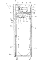
図1に示すように、冷蔵庫10は、収納室14を内部画成した断熱構造の箱体12と、この箱体12の上方に設けられ、金属パネル18により外壁を構成したキャビネット16とを備えている。箱体12には、前側に開放して物品の出し入れ口となる開口部12aが収納室14に連通して開設され、この開口部12aは、図示しないヒンジにより箱体12の前部に開閉可能に支持された断熱扉22で塞がれる。   As shown in FIG. 1, the refrigerator 10 includes a heat-insulated box 12 that defines a storage chamber 14, and a cabinet 16 that is provided above the box 12 and has an outer wall formed of a metal panel 18. ing. The box body 12 has an opening 12a that opens to the front side and serves as an entry / exit port for communicating with the storage chamber 14, and the opening 12a can be opened and closed to the front of the box body 12 by a hinge (not shown). The heat insulating door 22 supported by

前記キャビネット16の内部には、収納室14を冷却するための冷却設備31の一部および該冷却設備31を制御する制御用電装箱(図示せず)が配設される機械室20が画成される。機械室20の底部には、箱体12の天板12bに載置されて、該機械室20に配設する機器の共通基板となる台板24が設置されている。そして、キャビネット16の外壁をなす金属パネル18には、機械室20に連通する空気流通孔(図示せず)が適宜部位に開設され、この空気流通孔を介して機械室20内の雰囲気と外気とが入替わるようになっている。   Inside the cabinet 16 is a machine room 20 in which a part of a cooling facility 31 for cooling the storage chamber 14 and a control electrical box (not shown) for controlling the cooling facility 31 are arranged. Made. At the bottom of the machine room 20, a base plate 24 that is placed on the top plate 12 b of the box 12 and serves as a common substrate for the devices disposed in the machine room 20 is installed. The metal panel 18 forming the outer wall of the cabinet 16 is provided with air circulation holes (not shown) communicating with the machine room 20 at appropriate locations, and the atmosphere in the machine room 20 and the outside air are communicated through the air circulation holes. And are to be replaced.

前記収納室14の上部には、箱体12における天板12bの下面から所定間隔離間して冷却ダクト26が配設され、この冷却ダクト26と、箱体12の天板12bに開設した切欠口12cを介して収納室14側に臨む台板24との間に冷却室28が画成される。この冷却室28は、冷却ダクト26の底部前側に形成した吸込口26aおよび後側に形成した冷気吹出口26bを介して収納室14に連通している。吸込口26aには送風ファン30が配設され、該送風ファン30を駆動することで、吸込口26aから収納室14の空気を冷却室28に取込み、冷気吹出口26bから冷却室28の冷気が収納室14に送出される。天板12bの切欠口12cは、台板24で気密的に塞がれて、収納室14(冷却室28)と機械室20とは、台板24で区切られて互いに独立した空間となっている(図1参照)。   In the upper part of the storage chamber 14, a cooling duct 26 is disposed at a predetermined distance from the lower surface of the top plate 12b in the box 12, and the cooling duct 26 and a notch formed in the top plate 12b of the box 12 are provided. A cooling chamber 28 is defined between the base plate 24 facing the storage chamber 14 via 12c. The cooling chamber 28 communicates with the storage chamber 14 via a suction port 26 a formed on the front side of the bottom of the cooling duct 26 and a cold air outlet 26 b formed on the rear side. A blower fan 30 is disposed at the suction port 26a. By driving the blower fan 30, the air in the storage chamber 14 is taken into the cooling chamber 28 from the suction port 26a, and the cool air in the cooling chamber 28 is drawn from the cool air outlet 26b. It is sent to the storage chamber 14. The notch 12c of the top plate 12b is hermetically closed by the base plate 24, and the storage chamber 14 (cooling chamber 28) and the machine room 20 are separated from each other by the base plate 24 and become independent spaces. (See FIG. 1).

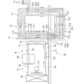
図2は、二次側の回路として前提例1に係る二次冷却装置(冷却装置)70を備える冷却設備31を示す概略回路図である。図2に示す如く、冷却設備31は、冷媒を強制循環する機械圧縮式の一次冷却装置(一次側の回路)34と、冷媒が自然対流するサーモサイフォンからなる二次冷却装置70とを、熱交換器HEを介して熱交換するように熱的に接続(カスケード接続)した二次ループ冷凍回路が採用される。熱交換器HEは、機械室20に設置され、一次冷却装置34を構成する一次熱交換部36と、この一次熱交換部36と別系統に形成されて、二次冷却装置70を構成する二次熱交換部(熱交換部)46とを備えている。すなわち、一次冷却装置34および二次冷却装置70には、独立した冷媒が循環する回路が夫々形成され、二次冷却装置70を循環する二次冷媒(冷媒)としては、毒性、可燃性および腐食性を有していない安全性の高い二酸化炭素が採用される。これに対し、一次冷却装置34を循環する一次冷媒としては、蒸発熱や飽和圧等の冷媒としての特性に優れているブタンやプロパン等のHC系の冷媒またはアンモニアなどが採用され、前提例1ではプロパンが用いられている。すなわち、冷却設備31は、冷媒としてフロンを使用する必要はない。なお、熱交換器HEとしては、例えばプレート式、二重管式およびその発展型またはそれに類するものが採用される。 FIG. 2 is a schematic circuit diagram showing a cooling facility 31 including a secondary cooling device (cooling device) 70 according to Premise Example 1 as a circuit on the secondary side. As shown in FIG. 2, the cooling facility 31 includes a mechanical compression type primary cooling device (primary side circuit) 34 that forcibly circulates a refrigerant and a secondary cooling device 70 that includes a thermosiphon that naturally convects the refrigerant. A secondary loop refrigeration circuit that is thermally connected (cascade connection) so as to exchange heat via the exchanger HE is employed. The heat exchanger HE is installed in the machine room 20 and is formed in a separate system from the primary heat exchange unit 36 that constitutes the primary cooling device 34 and the primary heat exchange unit 36, and constitutes the secondary cooling device 70. And a secondary heat exchange section (heat exchange section) 46. That is, the primary cooling device 34 and the secondary cooling device 70 are each formed with a circuit through which an independent refrigerant circulates. The secondary refrigerant (refrigerant) circulating through the secondary cooling device 70 is toxic, flammable, and corrosive. Highly safe carbon dioxide that does not have the property is adopted. In contrast, the primary refrigerant circulating in the primary cooling device 34, such as a HC-based refrigerant or ammonia, such as butane and propane has excellent properties as a refrigerant in evaporative heat or saturation pressure, etc. is employed, precondition 1 In propane is used. That is, the cooling facility 31 does not need to use chlorofluorocarbon as a refrigerant. In addition, as the heat exchanger HE, for example, a plate type, a double pipe type and the developed type thereof or the like are adopted.

前記一次冷却装置34は、気相一次冷媒を圧縮する圧縮機CMと、圧縮した一次冷媒を液化する凝縮器CDと、液相一次冷媒の圧力を低下させる膨張弁EVと、液相一次冷媒を気化する熱交換器HEの一次熱交換部36とを冷媒配管38で接続して構成される(図2参照)。圧縮機CMおよび凝縮器CDは、機械室20において台板24上に共通的に配設され、凝縮器CDを強制冷却する凝縮器ファンFMも、該凝縮器CDに対向して台板24上に配設されている。一次冷却装置34では、圧縮機CMによる一次冷媒の圧縮により、圧縮機CM、凝縮器CD、膨張弁EV、熱交換器HEの一次熱交換部36および圧縮機CMの順に、一次冷媒が強制循環され、各機器の作用下に一次熱交換部36において所要の冷却を行なうようになっている(図2参照)。   The primary cooling device 34 includes a compressor CM that compresses the gas phase primary refrigerant, a condenser CD that liquefies the compressed primary refrigerant, an expansion valve EV that reduces the pressure of the liquid primary refrigerant, and a liquid primary refrigerant. A primary heat exchanging portion 36 of the heat exchanger HE to be vaporized is connected by a refrigerant pipe 38 (see FIG. 2). The compressor CM and the condenser CD are commonly arranged on the base plate 24 in the machine room 20, and a condenser fan FM for forcibly cooling the condenser CD is also provided on the base plate 24 so as to face the condenser CD. It is arranged. In the primary cooling device 34, the primary refrigerant is forcibly circulated in the order of the compressor CM, the condenser CD, the expansion valve EV, the primary heat exchange unit 36 of the heat exchanger HE, and the compressor CM by the compression of the primary refrigerant by the compressor CM. The required cooling is performed in the primary heat exchange section 36 under the action of each device (see FIG. 2).

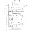
前記二次冷却装置70は、気相二次冷媒(気化冷媒)を液化する熱交換器HEの二次熱交換部46と、液相二次冷媒(液化冷媒)を気化する蒸発器EPとを備え、二次熱交換部46と蒸発器EPとが1対1の関係で対応している(図2参照)。また二次冷却装置70は、二次熱交換部46と蒸発器EPとを接続する液配管48およびガス配管50を備え、液配管48を介して二次熱交換部46から蒸発器EPへ重力の作用下に液相二次冷媒を供給し、ガス配管50を介して蒸発器EPから二次熱交換部46へ気相二次冷媒を還流させる自然循環回路72が設けられる。そして、前提例1の二次冷却装置70には、互いに独立した複数(図示の例では3回路)の自然循環回路72が並列に構築される。なお、二次熱交換部46は、機械室20に配設される一方、蒸発器EPは、当該機械室20の下方に位置する冷却室28に配設され、台板24を挟んで二次熱交換部46より下方に蒸発器EPが配置される。 The secondary cooling device 70 includes a secondary heat exchange unit 46 of a heat exchanger HE that liquefies a gas phase secondary refrigerant (vaporized refrigerant) and an evaporator EP that vaporizes the liquid phase secondary refrigerant (liquefied refrigerant). The secondary heat exchange section 46 and the evaporator EP correspond to each other in a one-to-one relationship (see FIG. 2). The secondary cooling device 70 also includes a liquid pipe 48 and a gas pipe 50 that connect the secondary heat exchange unit 46 and the evaporator EP, and the gravity is transferred from the secondary heat exchange unit 46 to the evaporator EP via the liquid pipe 48. A natural circulation circuit 72 is provided for supplying the liquid phase secondary refrigerant under the action of the above and returning the gas phase secondary refrigerant from the evaporator EP to the secondary heat exchange unit 46 via the gas pipe 50. In the secondary cooling device 70 of Premise Example 1, a plurality of (three circuits in the illustrated example) natural circulation circuits 72 independent from each other are constructed in parallel. The secondary heat exchange unit 46 is disposed in the machine room 20, while the evaporator EP is disposed in the cooling chamber 28 located below the machine room 20, with the base plate 24 interposed therebetween. The evaporator EP is disposed below the heat exchange unit 46.

前記二次熱交換部46には、凝縮経路47(特に区別する場合は、符号47にα,β,γ…を追加する。)が、並列して複数(前提例1では3本)設けられている。また蒸発器EPには、蒸発管(蒸発経路)52が、並列して複数(前提例1では3本であって、特に区別する場合は、符号52にα,β,γ…を追加する。)設けられている。図2では、凝縮経路47をガス配管50に接続する流入端47aから液配管48に接続する流出端47bまで直線的な経路で表わすと共に、蒸発管52を液配管48に接続する流入端52aからガス配管50に接続する流出端52bまで直線的な経路で表わしているが、凝縮経路47および蒸発管52を蛇行させても、直線状に形成してもよい。ここで、二次冷却装置70では、複数の凝縮経路47、複数の蒸発管52、複数の液配管48(特に区別する場合は、符号48にα,β,γ…を追加する。)および複数のガス配管50(特に区別する場合は、符号50にα,β,γ…を追加する。)が同数となる。各自然循環回路72において、液配管48は、上端(始端)を二次熱交換部46における凝縮経路47の流出端47bに接続して台板24を貫通して配管され、冷却室28側に位置する下端(終端)が蒸発器EPにおける蒸発管52の流入端52aに接続される。各自然循環回路72において、ガス配管50は、冷却室28側に位置する下端(始端)が蒸発器EPにおける蒸発管52の流出端52bに接続して台板24を貫通して配管され、機械室20側に位置する上端(終端)が二次熱交換部46における凝縮経路47の流入端47aに接続される。なお、符号74は、各自然循環回路72に冷媒を充填するために設けられた冷媒チャージポートである。 The secondary heat exchanging part 46, the condensation path 47 (for distinguishing particular, the reference numeral 47 alpha, beta, gamma ... Add.) Is provided with a plurality (in precondition 1 three) in parallel ing. Further, the evaporator EP has a plurality of evaporation pipes (evaporation paths) 52 in parallel (three in the precondition example 1, and α, β, γ... Are added to the reference numeral 52 when particularly distinguished. ) Is provided. In FIG. 2, the condensation path 47 is represented by a straight path from the inflow end 47 a connecting to the gas pipe 50 to the outflow end 47 b connecting to the liquid pipe 48, and from the inflow end 52 a connecting the evaporation pipe 52 to the liquid pipe 48. Although a straight path is shown up to the outflow end 52b connected to the gas pipe 50, the condensing path 47 and the evaporation pipe 52 may be meandered or formed in a straight line. Here, in the secondary cooling device 70, a plurality of condensing paths 47, a plurality of evaporating pipes 52, a plurality of liquid pipes 48 (α, β, γ. Gas pipes 50 (in particular, α, β, γ,... Are added to the reference numeral 50 when distinguished). In each natural circulation circuit 72, the liquid pipe 48 is piped through the base plate 24 by connecting the upper end (starting end) to the outflow end 47 b of the condensation path 47 in the secondary heat exchange section 46, and to the cooling chamber 28 side. The lower end (end) located is connected to the inflow end 52a of the evaporation pipe 52 in the evaporator EP. In each natural circulation circuit 72, the gas pipe 50 is piped through the base plate 24 with the lower end (starting end) located on the cooling chamber 28 side connected to the outflow end 52b of the evaporation pipe 52 in the evaporator EP. The upper end (terminal) located on the chamber 20 side is connected to the inflow end 47 a of the condensation path 47 in the secondary heat exchange unit 46. Reference numeral 74 denotes a refrigerant charge port provided to fill each natural circulation circuit 72 with a refrigerant.

前記二次冷却装置70では、各自然循環回路72において、強制冷却される一次熱交換部36との熱交換により冷却される二次熱交換部46と蒸発器EPとの間に温度勾配が形成され、二次冷媒が二次熱交換部46、液配管48、蒸発器EPおよびガス配管50を自然対流して二次熱交換部46に再び戻る冷媒の循環サイクルが形成される。なお、図2では、複数の蒸発管52が上下の関係となっているが、水平方向に並列させてもよい。   In the secondary cooling device 70, in each natural circulation circuit 72, a temperature gradient is formed between the secondary heat exchange unit 46 and the evaporator EP that are cooled by heat exchange with the primary heat exchange unit 36 that is forcibly cooled. Thus, a refrigerant circulation cycle is formed in which the secondary refrigerant naturally convects through the secondary heat exchange unit 46, the liquid pipe 48, the evaporator EP, and the gas pipe 50 and returns to the secondary heat exchange unit 46 again. In FIG. 2, the plurality of evaporation pipes 52 have a vertical relationship, but they may be arranged in parallel in the horizontal direction.

次に、前提例1に係る二次冷却装置70を備えた冷却設備31の作用について説明する。冷却設備31では、冷却運転を開始すると、一次冷却装置34および二次冷却装置70の夫々で冷媒の循環が開始される。先ず、一次冷却装置34について説明すると、圧縮機CMおよび凝縮器ファンFMが駆動され、圧縮機CMで気相一次冷媒が圧縮されて、この一次冷媒を冷媒配管38を介して凝縮器CDに供給して、凝縮器ファンFMによる強制冷却により凝縮液化することで液相とする。液相一次冷媒は、膨張手段EVで減圧され、熱交換器HEの一次熱交換部36において二次熱交換部46を流通する二次冷媒から熱を奪って(吸熱)一挙に膨張気化する。このように一次冷却装置34は、熱交換器HEにおいて、一次熱交換部36により二次熱交換部46を強制冷却するように機能している。そして、一次熱交換部36で蒸発した気相一次冷媒は、冷媒配管38を経て圧縮機CMに帰還する強制循環サイクルを繰返す。 Next, the effect | action of the cooling equipment 31 provided with the secondary cooling device 70 which concerns on the example 1 of an assumption is demonstrated. In the cooling facility 31, when the cooling operation is started, circulation of the refrigerant is started in each of the primary cooling device 34 and the secondary cooling device 70. First, the primary cooling device 34 will be described. The compressor CM and the condenser fan FM are driven, the gas phase primary refrigerant is compressed by the compressor CM, and this primary refrigerant is supplied to the condenser CD through the refrigerant pipe 38. Then, the liquid phase is obtained by condensing and liquefying by forced cooling by the condenser fan FM. The liquid primary refrigerant is depressurized by the expansion means EV, and in the primary heat exchange section 36 of the heat exchanger HE, heat is taken from the secondary refrigerant flowing through the secondary heat exchange section 46 (heat absorption) and is expanded and vaporized all at once. Thus, the primary cooling device 34 functions to forcibly cool the secondary heat exchange unit 46 by the primary heat exchange unit 36 in the heat exchanger HE. Then, the gas phase primary refrigerant evaporated in the primary heat exchange unit 36 repeats the forced circulation cycle that returns to the compressor CM through the refrigerant pipe 38.

前記二次冷却装置70では、二次熱交換部46が一次熱交換部36により冷却されているから、各自然循環回路72において二次熱交換部46の各凝縮経路47を流通する過程で気相二次冷媒が放熱して凝縮し、気相から液相に状態変化することで比重が増加するので、重力の作用下に二次熱交換部46の各凝縮経路47に沿って液相二次冷媒が流下する。二次冷却装置70では、二次熱交換部46を機械室20に配置する一方、蒸発器EPを機械室20の下方に位置する冷却室28に配設することで、二次熱交換部46と蒸発器EPとの間に落差を設けてある。すなわち、各自然循環回路72において、液相二次冷媒を、二次熱交換部46の下部に接続した液配管48を介して、蒸発器EPへ向けて重力の作用下に自然流下させることができる。液相二次冷媒は、蒸発器EPの各蒸発管52を流通する過程で該蒸発器EPの周囲雰囲気から熱を奪って蒸発して気相に移行する。気相二次冷媒は、ガス配管50を介して蒸発器EPから二次熱交換部46へ還流し、二次冷却装置70ではポンプやモータ等の動力を用いることなく、各自然循環回路72において、簡単な構成で二次冷媒が自然循環するサイクルが繰返される。   In the secondary cooling device 70, the secondary heat exchange unit 46 is cooled by the primary heat exchange unit 36, so that the natural circulation circuit 72 passes through each condensation path 47 of the secondary heat exchange unit 46 in the course of circulation. The phase secondary refrigerant dissipates heat and condenses, and the specific gravity increases due to the state change from the gas phase to the liquid phase. Therefore, the liquid phase secondary refrigerant flows along the respective condensation paths 47 of the secondary heat exchange unit 46 under the action of gravity. The next refrigerant flows down. In the secondary cooling device 70, the secondary heat exchange unit 46 is disposed in the machine room 20, while the evaporator EP is disposed in the cooling chamber 28 located below the machine room 20, thereby the secondary heat exchange unit 46. And an evaporator EP are provided with a head. That is, in each natural circulation circuit 72, the liquid phase secondary refrigerant is allowed to flow naturally under the action of gravity toward the evaporator EP via the liquid pipe 48 connected to the lower part of the secondary heat exchange section 46. it can. The liquid secondary refrigerant evaporates by taking heat from the ambient atmosphere of the evaporator EP in the process of flowing through each of the evaporator tubes 52 of the evaporator EP, and moves to the gas phase. The gas phase secondary refrigerant is refluxed from the evaporator EP to the secondary heat exchange unit 46 via the gas pipe 50, and the secondary cooling device 70 does not use power from a pump, a motor or the like in each natural circulation circuit 72. The cycle in which the secondary refrigerant naturally circulates with a simple configuration is repeated.

前記送風ファン30により吸込口26aから冷却室28に吸引された収納室14の空気を、冷却された蒸発器EPに吹付けることで、蒸発器EPと熱交換した空気が冷気となる。そして冷気を、冷却室28から冷気吹出口26bを介して収納室14に送出することで、収納室14が冷却される。冷気は、収納室14の内部を循環して、吸込口26aを介して再び冷却室28内に戻るサイクルを反復する。   By blowing the air in the storage chamber 14 sucked into the cooling chamber 28 from the suction port 26a by the blower fan 30 onto the cooled evaporator EP, the air heat-exchanged with the evaporator EP becomes cold air. The storage chamber 14 is cooled by sending the cool air from the cooling chamber 28 to the storage chamber 14 via the cool air outlet 26b. The cold air circulates inside the storage chamber 14 and repeats a cycle of returning to the cooling chamber 28 again through the suction port 26a.

前記二次冷却装置70では、夫々の自然循環回路72が、経路や配管の分岐を伴わず互いに独立して1つの回路を構成するように、凝縮経路47と蒸発管52とが液配管48およびガス配管50で接続されている。このように、各自然循環回路72は、互いに独立しているから、凝縮経路47,47同士および蒸発管52,52同士または凝縮経路47と蒸発管52との間で二次冷媒が偏在することを抑制でき、各凝縮経路47および各蒸発管52を流通する二次冷媒の量を一致させることができる。   In the secondary cooling device 70, the condensing path 47 and the evaporating pipe 52 are connected to the liquid pipe 48 and the evaporating pipe 52 so that each natural circulation circuit 72 forms one circuit independently of each other without branching the path or the pipe. They are connected by a gas pipe 50. As described above, since the natural circulation circuits 72 are independent of each other, the secondary refrigerant is unevenly distributed between the condensation paths 47 and 47 and between the evaporation pipes 52 and 52 or between the condensation path 47 and the evaporation pipe 52. The amount of secondary refrigerant flowing through each condensation path 47 and each evaporation pipe 52 can be matched.

また、二次冷却装置70に作用する外気温の変動等の外因によって、各自然循環回路72を循環する二次冷媒が凝縮経路47や蒸発管52の何れかに偏在する場合もある。しかるに、各自然循環回路72は、互いに独立したサーモサイフォンが構成されているので、各凝縮経路47および各蒸発管52における二次冷媒の量が一致するように、二次冷媒のバランスが自然に調節される。従って、各凝縮経路47および各蒸発管52において、二次冷媒の偏在自体が起きにくく、例え二次冷媒の偏在が生じても当該凝縮経路47および蒸発管52を流通する二次冷媒の量を一致させるよう調節力が作用するので、二次冷媒のバランスを調節するために弁等の調節手段を設ける必要がなく、二次冷却装置70の構成を簡易にできる。しかも、自然循環回路72において、二次冷媒が円滑に自然対流するから、蒸発器EPにおける冷却効率を向上することができる。そして、熱交換部46および蒸発器EPにおいて要求される熱交換面積に応じた数の自然循環回路72を冷却装置70に設けることで、必要とされる凝縮経路47および蒸発管52を熱交換部46および蒸発器EPに配置することができ、装置全体として必要とされる熱交換面積が担保される。   Further, the secondary refrigerant circulating in each natural circulation circuit 72 may be unevenly distributed in either the condensation path 47 or the evaporation pipe 52 due to external factors such as fluctuations in the outside air temperature acting on the secondary cooling device 70. However, since each of the natural circulation circuits 72 is composed of thermosiphons that are independent from each other, the balance of the secondary refrigerant naturally occurs so that the amount of the secondary refrigerant in each condensation path 47 and each evaporation pipe 52 matches. Adjusted. Therefore, in each condensation path 47 and each evaporation pipe 52, the uneven distribution of the secondary refrigerant itself hardly occurs. For example, even if the secondary refrigerant is unevenly distributed, the amount of the secondary refrigerant flowing through the condensation path 47 and the evaporation pipe 52 is reduced. Since the adjusting force acts so as to match, there is no need to provide adjusting means such as a valve in order to adjust the balance of the secondary refrigerant, and the configuration of the secondary cooling device 70 can be simplified. Moreover, since the secondary refrigerant smoothly convects naturally in the natural circulation circuit 72, the cooling efficiency in the evaporator EP can be improved. Then, by providing the cooling device 70 with the number of natural circulation circuits 72 corresponding to the heat exchange area required in the heat exchange unit 46 and the evaporator EP, the required condensation path 47 and the evaporation pipe 52 are connected to the heat exchange unit. 46 and the evaporator EP, and the heat exchange area required for the entire apparatus is secured.

前記二次冷却装置70では、熱交換器46および蒸発器EPの夫々に凝縮経路47および蒸発管52を複数配置することができる。すなわち、1本当たりの凝縮経路47および蒸発管52に要求される熱交換面積が小さくなり、各凝縮経路47および各蒸発管52の配管長を短くすることが可能となる。これにより、各凝縮経路47および各蒸発管52において、必要とされる配管長を稼ぐために蛇行させる回数を少なくでき、流通抵抗となる屈曲部分を減らせるから、当該凝縮経路47および蒸発管52を流通する二次冷媒の圧力損失を小さくすることができる。また各自然循環回路72は、液配管48、ガス配管50、凝縮経路47および蒸発管52を分岐させることなく、1つの冷媒の経路で構成しているから、配管等の分岐部に起因する圧力損失が発生しない。更に各自然循環回路72では、凝縮経路47と蒸発管52との間で自然対流に必要とされる二次冷媒のヘッド差を小さくできるので、凝縮経路47と蒸発管52との間で要求される落差が小さくなり、二次熱交換部46と蒸発器EPとの上下の配置間隔を狭くすることが可能となり、二次冷却装置70をコンパクトにできる。また、各自然循環回路72において、二次冷媒の圧力損失が小さいので、液配管48およびガス配管50として従来と比較して細い管径を選定しても、同一量の二次冷媒を回路内に循環させることができ、回路全体として充填する二次冷媒の量を削減することが可能となる。   In the secondary cooling device 70, a plurality of condensation paths 47 and a plurality of evaporation pipes 52 can be arranged in the heat exchanger 46 and the evaporator EP, respectively. That is, the heat exchange area required for each condensation path 47 and the evaporation pipe 52 is reduced, and the length of each condensation path 47 and each evaporation pipe 52 can be shortened. Thereby, in each condensation channel | path 47 and each evaporation pipe | tube 52, since the frequency | count of meandering in order to earn the required piping length can be decreased and the bending part used as distribution | circulation resistance can be reduced, the said condensation path | route 47 and the evaporation pipe | tube 52 can be reduced. The pressure loss of the secondary refrigerant that circulates can be reduced. In addition, each natural circulation circuit 72 is configured by one refrigerant path without branching the liquid pipe 48, the gas pipe 50, the condensation path 47, and the evaporation pipe 52. There is no loss. Further, in each natural circulation circuit 72, the head difference of the secondary refrigerant required for natural convection between the condensation path 47 and the evaporation pipe 52 can be reduced, so that it is required between the condensation path 47 and the evaporation pipe 52. The drop between the secondary heat exchanger 46 and the evaporator EP can be narrowed, and the secondary cooling device 70 can be made compact. Further, in each natural circulation circuit 72, since the pressure loss of the secondary refrigerant is small, the same amount of the secondary refrigerant is put in the circuit even if the liquid pipe 48 and the gas pipe 50 are selected with a smaller pipe diameter as compared with the conventional one. Therefore, it is possible to reduce the amount of secondary refrigerant to be filled in the entire circuit.

このように、各凝縮経路47および各蒸発管52の長さや断面積を減じることが可能であるので、二次熱交換部46や蒸発器EPをコンパクトにできると共に、循環する冷媒量を低減することで、自然循環回路72の圧力上昇を緩和する膨張タンク(図示せず)の容量等の付帯設備も小さくなるので、二次冷却装置70全体としてコンパクトにすることができ、コストダウンも可能となる。また液配管48、ガス配管50および蒸発管52等の配管を細径化することで、これらの配管48,50,52において耐圧性能を確保するために必要な肉厚を減ずることが可能となる。すなわち、各配管48,50,52が細径化したことだけでなく、各配管48,50,52の肉厚が減少することとの相乗によって、配管重量を一層削減することができ、コストを更に低減し得る。   Thus, since the length and cross-sectional area of each condensation path 47 and each evaporation pipe 52 can be reduced, the secondary heat exchange unit 46 and the evaporator EP can be made compact, and the amount of circulating refrigerant is reduced. As a result, incidental facilities such as the capacity of an expansion tank (not shown) that alleviates the pressure increase in the natural circulation circuit 72 are also reduced, so that the secondary cooling device 70 as a whole can be made compact and the cost can be reduced. Become. Further, by reducing the diameters of the pipes such as the liquid pipe 48, the gas pipe 50, and the evaporation pipe 52, it is possible to reduce the wall thickness necessary for ensuring pressure resistance performance in these pipes 48, 50, and 52. . In other words, not only the diameter of each pipe 48, 50, 52 is reduced, but also synergistic with the reduction of the thickness of each pipe 48, 50, 52, the pipe weight can be further reduced, and the cost can be reduced. Further reduction can be achieved.

ここで、液配管48、ガス配管50および蒸発管52等の配管の細径化によるコストの低減について具体的に説明する。
例えば、耐圧性能Pを有する配管の肉厚tは、以下の式で求められる。なお、σは材料の許容応力であり、Dは配管の外径である。
t=PD/2(σ+P)…(イ)
長さLの配管重量Mは、以下の式で求められる。なお、Cは材料の比重であり、Dは配管の内径である。
M=πLC(D−D )/4…(ロ)
また、D=D−2tと表わすことができるので、これを(ロ)式に代入すると、以下の式が導き出される。
M=πLC(Dt−t)…(ハ)
そして(ハ)式に(イ)式を代入すると、以下の式が導き出される。
M=(1−P/2(σ+P))×πLCPD/2(σ+P)…(ニ)
前記(ニ)式は、耐圧性能Pを有する配管の重量を示している。(ニ)式において、D以外の条件は不変とすると、π、L、C、P、σの条件は定数として扱うことができる。よって、耐圧性能Pを有する配管重量(配管の外径D)は、以下の式で表わすことができる。
M={(1−P/2(σ+P))×πLCP/2(σ+P)}×D…(ホ)
(ホ)式における{ }内は前述の如く定数であるから、M=ADと表わすことができる。
そして、耐圧性能Pを有する外径Dの配管の配管重量MDは、AD であり、耐圧性能Pを有する外径Dの配管の配管重量MDは、AD である。
更に、配管重量MDと配管重量MDとの比は、以下のように表わされる。
MD/MD=D /D …(ヘ)
Here, the cost reduction by reducing the diameter of the pipes such as the liquid pipe 48, the gas pipe 50, and the evaporation pipe 52 will be specifically described.
For example, the wall thickness t of the pipe having the pressure resistance performance P is obtained by the following equation. Here, σ is the allowable stress of the material, and D is the outer diameter of the pipe.
t = PD / 2 (σ + P) (B)
The pipe weight M of the length L is calculated | required with the following formula | equation. Incidentally, C is the specific gravity of the material, D i is the internal diameter of the pipe.
M = πLC (D 2 −D i 2 ) / 4 (b)
Further, since it can be expressed as D i = D−2t, substituting this into the expression (b) yields the following expression.
M = πLC (Dt−t 2 ) (C)
Then, by substituting (A) into (C), the following equation is derived.
M = (1-P / 2 (σ + P)) × πLCPD 2/2 (σ + P) ... ( d)
The expression (d) indicates the weight of the pipe having the pressure resistance performance P. In the expression (D), if conditions other than D are unchanged, the conditions of π, L, C, P, and σ can be treated as constants. Therefore, the weight of the pipe having the pressure resistance performance P (the outer diameter D of the pipe) can be expressed by the following expression.
M = {(1−P / 2 (σ + P)) × πLCP / 2 (σ + P)} × D 2 (e)
Since the value in {} in the expression (e) is a constant as described above, it can be expressed as M = AD 2 .
Then, the pipe weight MD 1 of the pipe outside diameter D 1 having a pressure resistance P is AD 1 2, pipe weight MD 2 of the outer diameter D 2 pipe having a pressure resistance P is AD 2 2.
Furthermore, the ratio of the pipe weight MD 1 and the pipe weight MD 2 is expressed as follows.
MD 2 / MD 1 = D 2 2 / D 1 2 (f)

前記(ヘ)式に具体的な数字を当てはめて説明する。一般的な冷却装置では、蒸発管の外径は9.52mmに設定されることが多い。これに対して、前提例1の冷却装置であれば、条件によっても変わるが外径6.35mmの蒸発管を用いることができる。これらの条件を前記(へ)式に当てはめると、以下のようになる。
MDφ6.35/MDφ9.52=(6.35)/(9.52)=0.44
また、前提例1の冷却装置において、外径4.76mmの蒸発管を用いた場合は、以下のようになる。
MDφ4.76/MDφ9.52=(4.76)/(9.52)=0.25
すなわち、配管の重量比は、配管の材料価格の比であるともいえるから、前提例1の二次冷却装置70によれば、従来の冷却装置と比較して配管が細径化することにより大幅なコスト削減を達成し得ることは明らかである。
The description will be made by applying specific numbers to the formula (f). In a general cooling device, the outer diameter of the evaporation tube is often set to 9.52 mm. On the other hand, if it is the cooling apparatus of the example 1 of an assumption , although it changes with conditions, an evaporation pipe with an outer diameter of 6.35 mm can be used. When these conditions are applied to the above equation (f), the following is obtained.
MD φ6.35 / MD φ9.52 = (6.35) 2 /(9.52) 2 = 0.44
Moreover, in the cooling device of the premise example 1, when an evaporation tube having an outer diameter of 4.76 mm is used, the following is obtained.
MD φ4.76 / MD φ9.52 = (4.76) 2 /(9.52) 2 = 0.25
In other words, the weight ratio of the pipe can be said to be the ratio of the material price of the pipe. Therefore, according to the secondary cooling device 70 of the precondition example 1, the pipe has a smaller diameter than the conventional cooling device. Clearly, significant cost savings can be achieved.

前記冷却設備31は、一次冷却装置34と二次冷却装置70とを熱交換器HEで接続し、この熱交換器HEにおいて、一次冷却装置34の一次冷媒と二次冷却装置70の二次冷媒とが蒸発および凝縮作用下に熱交換を行なう。すなわち、顕熱のみによる熱交換と比べて、非常に高い熱伝達率を持つので、一次冷却装置34と二次冷却装置70との間の伝熱面積を小さくすることができる。また、一次冷媒および二次冷媒は共に、潜熱により熱の輸送を行なうため、比較的少量で、多くの熱量を伝達することができるから、熱交換器HEにおける熱交換量を低下させることなく、一次冷却装置34および二次冷却装置70の内容積を小さくすることが可能となる。従って、一次冷却装置34の一次冷媒量および二次冷却装置70の二次冷媒量を何れも低減でき、コストダウンや、一次冷却装置34および二次冷却装置70の小型化による冷却設備31の省スペース化を図り得る。   The cooling facility 31 connects the primary cooling device 34 and the secondary cooling device 70 with a heat exchanger HE, and in this heat exchanger HE, the primary refrigerant of the primary cooling device 34 and the secondary refrigerant of the secondary cooling device 70 are connected. Perform heat exchange under the action of evaporation and condensation. That is, compared with heat exchange using only sensible heat, the heat transfer coefficient is extremely high, so that the heat transfer area between the primary cooling device 34 and the secondary cooling device 70 can be reduced. In addition, since both the primary refrigerant and the secondary refrigerant transport heat by latent heat, a large amount of heat can be transmitted in a relatively small amount, so that the amount of heat exchange in the heat exchanger HE is not reduced. The internal volumes of the primary cooling device 34 and the secondary cooling device 70 can be reduced. Therefore, both the primary refrigerant amount of the primary cooling device 34 and the secondary refrigerant amount of the secondary cooling device 70 can be reduced, and the cost of the cooling equipment 31 can be reduced by cost reduction and downsizing of the primary cooling device 34 and the secondary cooling device 70. Space can be achieved.

前記一次冷却装置34に必要とされる一次冷媒量が少ないから、法令等で規定された冷媒の使用上限量以下とすることができ、一次冷媒として使用する冷媒の種類についての選択肢の幅が広がる。また機械室20は、凝縮器CDおよび圧縮機CMを空冷する都合上、空気が入替えられる開放された空間とされる。このような機械室20に一次冷却装置34を配設してあるから、一次冷媒が万が一漏出したとしても、機械室20に留まるおそれはない。また、機械室20は、台板24により閉鎖空間である収納室14と気密的に区切られているから、漏出した一次冷媒が収納室14に流入することはなく、収納室14に収納した物品に由来するアンモニアや硫化水素等の腐食性ガスが、機械室20に流入することもない。しかも、冷却設備31を一次冷却装置34と二次冷却装置70との二次ループ式冷凍回路で構成することで、安全性に優れている二酸化炭素等を二次冷媒として選択することが可能となる。すなわち、二次冷却装置70では、蒸発器EPが収納室14(冷却室28)に臨むが、例えば二次冷媒が収納室14に漏出したとしても、使用者に対する安全を担保し得る。   Since the amount of primary refrigerant required for the primary cooling device 34 is small, the amount of refrigerant can be set below the upper limit of the amount of refrigerant stipulated by laws and regulations, and the range of options for the type of refrigerant used as the primary refrigerant is widened. . Further, the machine room 20 is an open space in which air is exchanged for the purpose of air-cooling the condenser CD and the compressor CM. Since the primary cooling device 34 is disposed in the machine room 20, even if the primary refrigerant leaks out, there is no possibility of staying in the machine room 20. Further, since the machine room 20 is airtightly separated from the storage room 14 which is a closed space by the base plate 24, the leaked primary refrigerant does not flow into the storage room 14, and the articles stored in the storage room 14 Corrosive gases such as ammonia and hydrogen sulfide derived from the above do not flow into the machine room 20. Moreover, by configuring the cooling facility 31 with a secondary loop refrigeration circuit of the primary cooling device 34 and the secondary cooling device 70, it is possible to select carbon dioxide or the like having excellent safety as the secondary refrigerant. Become. That is, in the secondary cooling device 70, the evaporator EP faces the storage chamber 14 (cooling chamber 28), but even if the secondary refrigerant leaks into the storage chamber 14, for example, safety for the user can be ensured.

前記一次冷却装置34および二次冷却装置70は、熱交換器HEの一次熱交換部36と二次熱交換部46とで熱的に接続されているが、冷媒の循環経路として互いに独立している。冷却設備31を停止(圧縮機CM:停止)した際に、一次冷却装置34には凝縮器CDから高温の液相一次冷媒が一次熱交換部36に流入する。これにより熱交換器HEは昇温されるものの、二次冷却装置70は独立しているから、蒸発器EPは昇温されることはなく、冷却設備31を停止した際の収納室14の温度上昇が緩やかになる。すなわち、冷却設備31により収納室14を所要の設定温度まで冷却することで、冷却設備31を停止した後、冷却設備31を再度駆動するまでの時間を長くすることができる。よって、冷却設備31の稼働率が低下するので、消費電力量の削減に繋がる。   The primary cooling device 34 and the secondary cooling device 70 are thermally connected by the primary heat exchange unit 36 and the secondary heat exchange unit 46 of the heat exchanger HE, but are independent of each other as a refrigerant circulation path. Yes. When the cooling facility 31 is stopped (compressor CM: stopped), the high-temperature liquid-phase primary refrigerant flows into the primary heat exchanger 36 from the condenser CD into the primary cooling device 34. As a result, the temperature of the heat exchanger HE is raised, but the secondary cooling device 70 is independent, so the evaporator EP is not heated, and the temperature of the storage chamber 14 when the cooling facility 31 is stopped. The rise will be moderate. That is, by cooling the storage chamber 14 to a required set temperature by the cooling facility 31, it is possible to lengthen the time until the cooling facility 31 is driven again after the cooling facility 31 is stopped. Therefore, since the operation rate of the cooling facility 31 is reduced, the power consumption is reduced.

このように、前提例1の二次冷却装置70を二次ループ式冷凍回路からなる冷却設備31に適用することで、従来のフロンを用いた冷却設備と同等の大きさおよびコストで当該冷却設備31を設計することが可能となり、冷媒としてフロンを使用した機械圧縮式の冷凍回路と比較して、装置全体が大型化して大きな設置面積を要すると共にコストの上昇を伴う欠点が解消されて市場での競争力を獲得することができる。すなわち、前提例1に係る二次冷却装置70は、地球温暖化防止の観点から重要視されている二次ループ式冷凍回路によるノンフロン化技術の普及を推進する上で、有効な技術的な位置付けを有している。 In this way, by applying the secondary cooling device 70 of Premise Example 1 to the cooling facility 31 composed of the secondary loop refrigeration circuit, the cooling facility can be equal in size and cost to the conventional cooling facility using CFCs. 31 can be designed, and compared with a mechanical compression refrigeration circuit using chlorofluorocarbon as a refrigerant, the entire apparatus becomes larger and requires a large installation area, and the disadvantages associated with an increase in cost are eliminated in the market. Can be competitive. That is, the secondary cooling device 70 according to the premise example 1 is an effective technical position in promoting the spread of non-fluorocarbon technology using a secondary loop refrigeration circuit, which is regarded as important from the viewpoint of preventing global warming. have.

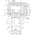
図3は、二次側の回路として前提例2に係る二次冷却装置(冷却装置)44を備える冷却設備32を示す概略回路図である。なお、前提例2の冷却設備32は、前提例1で説明した冷蔵庫10に設置される。 FIG. 3 is a schematic circuit diagram showing a cooling facility 32 including a secondary cooling device (cooling device) 44 according to Precondition Example 2 as a secondary-side circuit. The cooling equipment 32 assumptions Example 2 is placed in the refrigerator 10 described on the assumption Example 1.

図3に示す如く、前提例2に係る冷却設備32は、冷媒を強制循環する機械圧縮式の一次冷却装置(一次側の回路)34と、冷媒が自然対流するサーモサイフォンからなる二次冷却装置(冷却装置)44とを、熱交換器HEを介して熱交換するように熱的に接続(カスケード接続)した二次ループ冷凍回路が採用される。熱交換器HEは、機械室20に設置され、一次冷却装置34を構成する一次熱交換部36と、この一次熱交換部36と別系統に形成されて、二次冷却装置44を構成する二次熱交換部(熱交換部)46とを備えている。すなわち、一次冷却装置34および二次冷却装置44には、独立した冷媒が循環する回路が夫々形成され、二次冷却装置44を循環する二次冷媒(冷媒)としては、毒性、可燃性および腐食性を有していない安全性の高い二酸化炭素が採用される。これに対し、一次冷却装置34を循環する一次冷媒としては、蒸発熱や飽和圧等の冷媒としての特性に優れているブタンやプロパン等のHC系の冷媒またはアンモニアなどが採用され、前提例2ではプロパンが用いられている。すなわち、冷却設備32は、冷媒としてフロンを使用する必要はない。なお、熱交換器HEとしては、例えばプレート式、二重管式およびその発展型またはそれに類するものが採用される。 As shown in FIG. 3, the cooling facility 32 according to Precondition 2 includes a mechanical compression primary cooling device (primary side circuit) 34 that forcibly circulates a refrigerant and a secondary cooling device that includes a thermosiphon that naturally convects the refrigerant. A secondary loop refrigeration circuit in which the (cooling device) 44 is thermally connected (cascade connection) so as to exchange heat with the heat exchanger HE is employed. The heat exchanger HE is installed in the machine room 20, and is formed in a separate system from the primary heat exchange unit 36 that constitutes the primary cooling device 34 and the primary heat exchange unit 36, and constitutes the secondary cooling device 44. And a secondary heat exchange section (heat exchange section) 46. That is, the primary cooling device 34 and the secondary cooling device 44 are each formed with a circuit through which an independent refrigerant circulates. The secondary refrigerant (refrigerant) circulating through the secondary cooling device 44 is toxic, flammable, and corrosive. Highly safe carbon dioxide that does not have the property is adopted. In contrast, the primary refrigerant circulating in the primary cooling device 34, such as a HC-based refrigerant or ammonia, such as butane and propane has excellent properties as a refrigerant in evaporative heat or saturation pressure, etc. is employed, precondition 2 In propane is used. That is, the cooling facility 32 does not need to use chlorofluorocarbon as a refrigerant. In addition, as the heat exchanger HE, for example, a plate type, a double pipe type and the developed type thereof or the like are adopted.

前記一次冷却装置34は、気相一次冷媒を圧縮する圧縮機CMと、圧縮した一次冷媒を液化する凝縮器CDと、液相一次冷媒の圧力を低下させる膨張弁EVと、液相一次冷媒を気化する熱交換器HEの一次熱交換部36とを冷媒配管38で接続して構成される(図3参照)。圧縮機CMおよび凝縮器CDは、機械室20において台板24上に共通的に配設され、凝縮器CDを強制冷却する凝縮器ファンFMも、該凝縮器CDに対向して台板24上に配設されている。一次冷却装置34では、圧縮機CMによる一次冷媒の圧縮により、圧縮機CM、凝縮器CD、膨張弁EV、熱交換器HEの一次熱交換部36および圧縮機CMの順に、一次冷媒が強制循環され、各機器の作用下に一次熱交換部36において所要の冷却を行なうようになっている(図3参照)。   The primary cooling device 34 includes a compressor CM that compresses the gas phase primary refrigerant, a condenser CD that liquefies the compressed primary refrigerant, an expansion valve EV that reduces the pressure of the liquid primary refrigerant, and a liquid primary refrigerant. A primary heat exchanging portion 36 of the heat exchanger HE to be vaporized is connected by a refrigerant pipe 38 (see FIG. 3). The compressor CM and the condenser CD are commonly arranged on the base plate 24 in the machine room 20, and a condenser fan FM for forcibly cooling the condenser CD is also provided on the base plate 24 so as to face the condenser CD. It is arranged. In the primary cooling device 34, the primary refrigerant is forcibly circulated in the order of the compressor CM, the condenser CD, the expansion valve EV, the primary heat exchange unit 36 of the heat exchanger HE, and the compressor CM by the compression of the primary refrigerant by the compressor CM. The required cooling is performed in the primary heat exchange section 36 under the action of each device (see FIG. 3).

前記二次冷却装置44は、気相二次冷媒(気化冷媒)を液化する熱交換器HEの二次熱交換部46と、液相二次冷媒(液化冷媒)を気化する蒸発器EPとを備え、二次熱交換部46と蒸発器EPとが1対1の関係で対応している(図3参照)。また二次冷却装置44は、二次熱交換部46と蒸発器EPとを接続する液配管48およびガス配管50を備え、液配管48を介して二次熱交換部46から蒸発器EPへ重力の作用下に液相二次冷媒を供給し、ガス配管50を介して蒸発器EPから二次熱交換部46へ気相二次冷媒を還流させる自然循環回路45が設けられる。前述した如く、二次熱交換部46は、機械室20に配設される一方、蒸発器EPは、当該機械室20の下方に位置する冷却室28に配設され、台板24を挟んで二次熱交換部46より下方に蒸発器EPが配置される。なお、符号74は、自然循環回路45に冷媒を充填するために設けられた冷媒チャージポートであって、前提例2の二次冷却装置44では、自然循環回路45が単一であるから、冷媒チャージポート74および安全弁や膨張タンク(何れも図示せず)等の付帯設備が1組で足りる。 The secondary cooling device 44 includes a secondary heat exchange unit 46 of a heat exchanger HE that liquefies a gas phase secondary refrigerant (vaporized refrigerant) and an evaporator EP that vaporizes the liquid phase secondary refrigerant (liquefied refrigerant). The secondary heat exchange section 46 and the evaporator EP correspond to each other in a one-to-one relationship (see FIG. 3). Further, the secondary cooling device 44 includes a liquid pipe 48 and a gas pipe 50 that connect the secondary heat exchange unit 46 and the evaporator EP, and gravity is passed from the secondary heat exchange unit 46 to the evaporator EP via the liquid pipe 48. A natural circulation circuit 45 is provided that supplies the liquid phase secondary refrigerant under the action of the above and recirculates the gas phase secondary refrigerant from the evaporator EP to the secondary heat exchange unit 46 via the gas pipe 50. As described above, the secondary heat exchange unit 46 is disposed in the machine room 20, while the evaporator EP is disposed in the cooling chamber 28 located below the machine room 20 and sandwiches the base plate 24. An evaporator EP is disposed below the secondary heat exchange unit 46. Reference numeral 74 denotes a refrigerant charge port provided for charging the natural circulation circuit 45 with the refrigerant. In the secondary cooling device 44 of the precondition example 2 , since the natural circulation circuit 45 is single, One set of incidental facilities such as a charge port 74, a safety valve, and an expansion tank (both not shown) are sufficient.

前記二次熱交換部46には、凝縮経路47(特に区別する場合は、符号47にα,β,γ…を追加する。)が、並列して複数(前提例2では3本)設けられている。また蒸発器EPには、蒸発管(蒸発経路)52が、並列して複数(前提例2では3本であって、特に区別する場合は、符号52にα,β,γ…を追加する。)設けられている。図3では、凝縮経路47をガス配管50に接続する流入端47aから液配管48に接続する流出端47bまで直線的な経路で表わすと共に、蒸発管52を液配管48に接続する流入端52aからガス配管50に接続する流出端52bまで直線的な経路で表わしているが、凝縮経路47および蒸発管52を蛇行させても、直線状に形成してもよい。ここで、二次冷却装置44では、複数の凝縮経路47、複数の蒸発管52、複数の液配管48(特に区別する場合は、符号48にα,β,γ…を追加する。)および複数のガス配管50(特に区別する場合は、符号50にα,β,γ…を追加する。)が同数に設定されている。液配管48は、上端(始端)を二次熱交換部46における凝縮経路47の流出端47bに接続して台板24を貫通して配管され、冷却室28側に位置する下端(終端)が蒸発器EPにおける蒸発管52の流入端52aに接続される。そして、ガス配管50は、冷却室28側に位置する下端(始端)が蒸発器EPにおける蒸発管52の流出端52bに接続して台板24を貫通して配管され、機械室20側に位置する上端(終端)が二次熱交換部46における凝縮経路47の流入端47aに接続される。 The secondary heat exchanging part 46, the condensation path 47 (for distinguishing particular, the reference numeral 47 alpha, beta, gamma ... Add.) Is provided with a plurality (in precondition 2 three) in parallel ing. Further, in the evaporator EP, there are a plurality of evaporation tubes (evaporation paths) 52 in parallel (three in the precondition 2) , and α, β, γ. ) Is provided. In FIG. 3, the condensation path 47 is represented by a straight path from the inflow end 47 a connecting to the gas pipe 50 to the outflow end 47 b connecting to the liquid pipe 48, and from the inflow end 52 a connecting the evaporation pipe 52 to the liquid pipe 48. Although a straight path is shown up to the outflow end 52b connected to the gas pipe 50, the condensing path 47 and the evaporation pipe 52 may be meandered or formed in a straight line. Here, in the secondary cooling device 44, a plurality of condensation paths 47, a plurality of evaporation pipes 52, a plurality of liquid pipes 48 (α, β, γ,. Gas pipes 50 (in particular, α, β, γ,... Are added to the reference numeral 50 when distinguished) are set to the same number. The liquid pipe 48 is piped through the base plate 24 by connecting the upper end (starting end) to the outflow end 47b of the condensation path 47 in the secondary heat exchanging section 46, and the lower end (end) located on the cooling chamber 28 side. It is connected to the inflow end 52a of the evaporation pipe 52 in the evaporator EP. The gas pipe 50 has a lower end (starting end) located on the cooling chamber 28 side connected to the outflow end 52b of the evaporation pipe 52 in the evaporator EP and is piped through the base plate 24, and is located on the machine room 20 side. The upper end (termination) is connected to the inflow end 47a of the condensation path 47 in the secondary heat exchange section 46.

前記二次冷却装置44では、凝縮経路47の流出端47bに接続する液配管48を、当該凝縮経路47の流入端47aに連結したガス配管50が接続している蒸発管52と別の蒸発管52に接続するよう構成される。また二次冷却装置44では、蒸発管52の流出端52bに接続するガス配管50を、当該蒸発管52の流入端52aに連結した液配管48が接続している凝縮経路47と別の凝縮経路47に接続して、複数の凝縮経路47、複数の蒸発管52、複数の液配管48および複数のガス配管50によって、全体として1つの自然循環回路45が構成される。そして、二次冷却装置44には、強制冷却される一次熱交換部36との熱交換により冷却される二次熱交換部46と蒸発器EPとの間に温度勾配が形成され、二次冷媒が二次熱交換部46、液配管48、蒸発器EPおよびガス配管50を自然対流して二次熱交換部46に再び戻る冷媒の循環サイクルが形成される。なお、図3では、複数の蒸発管52が上下の関係となっているが、水平方向に並列させてもよい。   In the secondary cooling device 44, the liquid pipe 48 connected to the outflow end 47b of the condensation path 47 is different from the evaporation pipe 52 connected to the gas pipe 50 connected to the inflow end 47a of the condensation path 47. 52 is configured to connect. Further, in the secondary cooling device 44, the gas pipe 50 connected to the outflow end 52 b of the evaporation pipe 52 is different from the condensation path 47 connected to the liquid pipe 48 connected to the inflow end 52 a of the evaporation pipe 52. 47, a plurality of condensation paths 47, a plurality of evaporation pipes 52, a plurality of liquid pipes 48, and a plurality of gas pipes 50 constitute one natural circulation circuit 45 as a whole. In the secondary cooling device 44, a temperature gradient is formed between the secondary heat exchange unit 46 cooled by the heat exchange with the primary heat exchange unit 36 that is forcibly cooled and the evaporator EP, and the secondary refrigerant However, a circulation cycle of the refrigerant is formed in which the secondary heat exchange unit 46, the liquid pipe 48, the evaporator EP, and the gas pipe 50 are naturally convected and returned to the secondary heat exchange unit 46 again. In FIG. 3, the plurality of evaporation pipes 52 have a vertical relationship, but may be arranged in parallel in the horizontal direction.

前記二次冷却装置44に構成される自然循環回路45について、図3を参照してより具体的に説明する。前提例2の二次冷却装置44では、二次熱交換部46に冷媒経路として3本の凝縮経路47α,47β,47γが設けられ、蒸発器EPに冷媒経路として3本の蒸発管52α,52β,52γが設けられている。第1凝縮経路47αの流出端47bには、第1液配管48αの始端が接続され、該第1液配管48αの終端が第1蒸発管52αの流入端52aに接続され、第1凝縮経路47αから第1液配管48αを介して第1蒸発管52αに二次液化冷媒が供給される。第1蒸発管52αの流出端52bには、第1ガス配管50αの始端が接続され、該第1ガス配管50αの終端が第2凝縮経路47βの流入端47aに接続され、第1蒸発管52αから第1ガス配管50αを介して第2凝縮経路47βに二次気化冷媒が戻される。第2凝縮経路47βの流出端47bには、第2液配管48βの始端が接続され、該第2液配管48βの終端が第2蒸発管52βの流入端52aに接続され、第2凝縮経路47βから第2液配管48βを介して第2蒸発管52βに二次液化冷媒が供給される。第2蒸発管52βの流出端52bには、第2ガス配管50βの始端が接続され、該第2ガス配管50βの終端が第3凝縮経路47γの流入端47aに接続され、第2蒸発管52βから第2ガス配管50βを介して第3凝縮経路47γに二次気化冷媒が戻される。第3凝縮経路47γの流出端47bには、第3液配管48γの始端が接続され、該第3液配管48γの終端が第3蒸発管52γの流入端52aに接続され、第3凝縮経路47γから第3液配管48γを介して第3蒸発管52γに二次液化冷媒が供給される。第3蒸発管52γの流出端52bには、第3ガス配管50γの始端が接続され、該第3ガス配管50γの終端が第1凝縮経路47αの流入端47aに接続され、第3蒸発管52γから第3ガス配管50γを介して第1凝縮経路47αに二次気化冷媒が戻され、二次冷媒が自然循環回路45内を一巡する。 The natural circulation circuit 45 configured in the secondary cooling device 44 will be described more specifically with reference to FIG. In the secondary cooling device 44 of the precondition example 2 , the secondary heat exchange unit 46 is provided with three condensation paths 47α, 47β, 47γ as refrigerant paths, and the evaporator EP has three evaporation pipes 52α, 52β as refrigerant paths. , 52γ. The starting end of the first liquid pipe 48α is connected to the outflow end 47b of the first condensing path 47α, the end of the first liquid pipe 48α is connected to the inflow end 52a of the first evaporation pipe 52α, and the first condensing path 47α. Is supplied to the first evaporation pipe 52α through the first liquid pipe 48α. The outflow end 52b of the first evaporation pipe 52α is connected to the start end of the first gas pipe 50α, the end of the first gas pipe 50α is connected to the inflow end 47a of the second condensation path 47β, and the first evaporation pipe 52α. The secondary vaporized refrigerant is returned to the second condensing path 47β through the first gas pipe 50α. The outflow end 47b of the second condensing path 47β is connected to the starting end of the second liquid pipe 48β, the end of the second liquid pipe 48β is connected to the inflow end 52a of the second evaporation pipe 52β, and the second condensing path 47β. Is supplied to the second evaporation pipe 52β through the second liquid pipe 48β. The outflow end 52b of the second evaporation pipe 52β is connected to the start end of the second gas pipe 50β, the end of the second gas pipe 50β is connected to the inflow end 47a of the third condensation path 47γ, and the second evaporation pipe 52β. The secondary vaporized refrigerant is returned to the third condensing path 47γ through the second gas pipe 50β. The outflow end 47b of the third condensing path 47γ is connected to the start end of the third liquid pipe 48γ, the end of the third liquid pipe 48γ is connected to the inflow end 52a of the third evaporation pipe 52γ, and the third condensing path 47γ. To the third evaporation pipe 52γ through the third liquid pipe 48γ. The start end of the third gas pipe 50γ is connected to the outflow end 52b of the third evaporation pipe 52γ, the end of the third gas pipe 50γ is connected to the inflow end 47a of the first condensation path 47α, and the third evaporation pipe 52γ. The secondary vaporized refrigerant is returned to the first condensing path 47α through the third gas pipe 50γ, and the secondary refrigerant makes a round in the natural circulation circuit 45.

次に、前提例2に係る二次冷却装置44を備えた冷却設備32の作用について説明する。冷却設備32では、冷却運転を開始すると、一次冷却装置34および二次冷却装置44の夫々で冷媒の循環が開始される。なお、一次冷却装置34の作用は、段落[0023]で説明しているので省略する。 Next, the effect | action of the cooling equipment 32 provided with the secondary cooling device 44 which concerns on the example 2 of an assumption is demonstrated. In the cooling facility 32, when the cooling operation is started, circulation of the refrigerant is started in each of the primary cooling device 34 and the secondary cooling device 44. In addition, since the effect | action of the primary cooling device 34 is demonstrated in the paragraph [0023], it abbreviate | omits.

前記二次冷却装置44では、二次熱交換部46が一次熱交換部36により冷却されているから、二次熱交換部46の各凝縮経路47を流通する過程で気相二次冷媒が放熱して凝縮し、気相から液相に状態変化することで比重が増加するので、重力の作用下に二次熱交換部46の各凝縮経路47に沿って液相二次冷媒が流下する。二次冷却装置44では、二次熱交換部46を機械室20に配置する一方、蒸発器EPを機械室20の下方に位置する冷却室28に配設することで、二次熱交換部46と蒸発器EPとの間に落差を設けてある。すなわち、液相二次冷媒を、二次熱交換部46の下部に接続した液配管48を介して、蒸発器EPへ向けて重力の作用下に自然流下させることができる。液相二次冷媒は、蒸発器EPの各蒸発管52を流通する過程で該蒸発器EPの周囲雰囲気から熱を奪って蒸発して気相に移行する。気相二次冷媒は、ガス配管50を介して蒸発器EPから二次熱交換部46へ還流し、二次冷却装置44ではポンプやモータ等の動力を用いることなく、簡単な構成で二次冷媒が自然循環するサイクルが繰返される。   In the secondary cooling device 44, since the secondary heat exchange unit 46 is cooled by the primary heat exchange unit 36, the gas phase secondary refrigerant dissipates heat in the course of flowing through each condensation path 47 of the secondary heat exchange unit 46. Then, the specific gravity increases by condensing and changing the state from the gas phase to the liquid phase, so that the liquid phase secondary refrigerant flows down along the respective condensation paths 47 of the secondary heat exchange section 46 under the action of gravity. In the secondary cooling device 44, the secondary heat exchange unit 46 is disposed in the machine room 20, while the evaporator EP is disposed in the cooling chamber 28 located below the machine room 20, thereby the secondary heat exchange unit 46. And an evaporator EP are provided with a head. That is, the liquid phase secondary refrigerant can be naturally flowed under the action of gravity toward the evaporator EP via the liquid pipe 48 connected to the lower portion of the secondary heat exchange section 46. The liquid secondary refrigerant evaporates by taking heat from the ambient atmosphere of the evaporator EP in the process of flowing through each of the evaporator tubes 52 of the evaporator EP, and moves to the gas phase. The gas phase secondary refrigerant is refluxed from the evaporator EP to the secondary heat exchanging unit 46 through the gas pipe 50, and the secondary cooling device 44 is a secondary with a simple configuration without using power of a pump, a motor, or the like. The cycle in which the refrigerant naturally circulates is repeated.

前記二次冷却装置44に構成した自然循環回路45では、複数の凝縮経路47とこの凝縮経路47と同数の蒸発管52とを互い違いに接続することで、1本の凝縮経路47と1本の蒸発管52とに交互に二次冷媒を流通させる1つのサーモサイフォンを形成してある。すなわち、自然循環回路45によれば、液配管48、ガス配管50、凝縮経路47および蒸発管52を分岐させることなく、1つの回路の中に複数の凝縮経路47および複数の蒸発管52を設けることができる。このように、自然循環回路45が全体として1つの冷媒の経路で構成されているから、凝縮経路47,47同士および蒸発管52,52同士または凝縮経路47と蒸発管52との間で二次冷媒が偏在することを抑制でき、各凝縮経路47および各蒸発管52を流通する二次冷媒の量を一致させることができる。   In the natural circulation circuit 45 configured in the secondary cooling device 44, one condensing path 47 and one condensing path 47 are connected by alternately connecting a plurality of condensing paths 47 and the same number of condensing paths 47 as the number of evaporating pipes 52. One thermosiphon that allows the secondary refrigerant to flow alternately to the evaporation pipe 52 is formed. That is, according to the natural circulation circuit 45, the plurality of condensation paths 47 and the plurality of evaporation pipes 52 are provided in one circuit without branching the liquid pipe 48, the gas pipe 50, the condensation path 47 and the evaporation pipe 52. be able to. As described above, the natural circulation circuit 45 is constituted by a single refrigerant path as a whole, so that the secondary is between the condensation paths 47 and 47 and between the evaporation pipes 52 and 52 or between the condensation path 47 and the evaporation pipe 52. The uneven distribution of the refrigerant can be suppressed, and the amount of the secondary refrigerant flowing through each condensation path 47 and each evaporation pipe 52 can be matched.

また、二次冷却装置44に作用する外気温の変動等の外因によって、自然循環回路45を循環する二次冷媒が凝縮経路47や蒸発管52の何れかに偏在する場合もある。しかるに、自然循環回路45は、1つのサーモサイフォンから構成されているので、各凝縮経路47および各蒸発管52における二次冷媒の量が一致するように、二次冷媒のバランスが自然に調節される。従って、各凝縮経路47および各蒸発管52において、二次冷媒の偏在自体が起きにくく、例え二次冷媒の偏在が生じても当該凝縮経路47および蒸発管52を流通する二次冷媒の量を一致させるよう調節力が作用するので、二次冷媒のバランスを調節するために弁等の調節手段を設ける必要がなく、二次冷却装置44の構成を簡易にできる。しかも、自然循環回路45において、二次冷媒が円滑に自然対流するから、蒸発器EPにおける冷却効率を向上することができる。従って、二次熱交換部46および蒸発器EPに凝縮経路47および蒸発管52を複数設けることができ、凝縮経路47および蒸発管52を屈曲や分岐することなく、熱交換面積を稼ぐことができる。   Further, the secondary refrigerant circulating in the natural circulation circuit 45 may be unevenly distributed in either the condensation path 47 or the evaporation pipe 52 due to external factors such as fluctuations in the outside air temperature acting on the secondary cooling device 44. However, since the natural circulation circuit 45 is composed of one thermosyphon, the balance of the secondary refrigerant is naturally adjusted so that the amount of the secondary refrigerant in each condensing path 47 and each evaporation pipe 52 matches. The Therefore, in each condensation path 47 and each evaporation pipe 52, the uneven distribution of the secondary refrigerant itself hardly occurs. For example, even if the secondary refrigerant is unevenly distributed, the amount of the secondary refrigerant flowing through the condensation path 47 and the evaporation pipe 52 is reduced. Since the adjusting force acts so as to match, it is not necessary to provide adjusting means such as a valve in order to adjust the balance of the secondary refrigerant, and the configuration of the secondary cooling device 44 can be simplified. In addition, since the secondary refrigerant smoothly convects naturally in the natural circulation circuit 45, the cooling efficiency in the evaporator EP can be improved. Accordingly, a plurality of condensation paths 47 and evaporation pipes 52 can be provided in the secondary heat exchange unit 46 and the evaporator EP, and a heat exchange area can be gained without bending or branching the condensation paths 47 and the evaporation pipes 52. .

前記二次冷却装置44では、熱交換器46および蒸発器EPの夫々に凝縮経路47および蒸発管52を複数配置することができる。すなわち、1本当たりの凝縮経路47および蒸発管52に要求される熱交換面積が小さくなり、各凝縮経路47および各蒸発管52の配管長を短くすることが可能となる。これにより、各凝縮経路47および各蒸発管52において、必要とされる配管長を稼ぐために蛇行させる回数を少なくでき、流通抵抗となる屈曲部分を減らせるから、当該凝縮経路47および蒸発管52を流通する二次冷媒の圧力損失を小さくすることができる。また、二次冷却装置44は、液配管48、ガス配管50、凝縮経路47および蒸発管52を分岐させることなく、自然循環回路45を全体として1つの冷媒の経路で構成しているから、配管等の分岐部に起因する圧力損失が発生しない。自然循環回路45では、凝縮経路47と蒸発管52との間で自然対流に必要とされる二次冷媒のヘッド差を小さくできるので、凝縮経路47と蒸発管52との間で要求される落差が小さくなり、二次熱交換部46と蒸発器EPとの上下の配置間隔を狭くすることが可能となり、二次冷却装置44をコンパクトにできる。また、自然循環回路45において、二次冷媒の圧力損失が小さいので、液配管48およびガス配管50として従来と比較して細い管径を選定しても、同一量の二次冷媒を回路内に循環させることができ、回路全体として充填する二次冷媒の量を削減することが可能となる。   In the secondary cooling device 44, a plurality of condensation paths 47 and a plurality of evaporation pipes 52 can be arranged in the heat exchanger 46 and the evaporator EP, respectively. That is, the heat exchange area required for each condensation path 47 and the evaporation pipe 52 is reduced, and the length of each condensation path 47 and each evaporation pipe 52 can be shortened. Thereby, in each condensation channel | path 47 and each evaporation pipe | tube 52, since the frequency | count of meandering in order to earn the required piping length can be decreased and the bending part used as distribution | circulation resistance can be reduced, the said condensation path | route 47 and the evaporation pipe | tube 52 can be reduced. The pressure loss of the secondary refrigerant that circulates can be reduced. Further, the secondary cooling device 44 does not branch the liquid pipe 48, the gas pipe 50, the condensing path 47, and the evaporation pipe 52, and the natural circulation circuit 45 is configured as a single refrigerant path as a whole. No pressure loss due to the branching part. In the natural circulation circuit 45, the head difference of the secondary refrigerant required for natural convection between the condensation path 47 and the evaporation pipe 52 can be reduced, so that a drop required between the condensation path 47 and the evaporation pipe 52 is required. Becomes smaller, the vertical arrangement interval between the secondary heat exchange section 46 and the evaporator EP can be narrowed, and the secondary cooling device 44 can be made compact. Further, in the natural circulation circuit 45, since the pressure loss of the secondary refrigerant is small, the same amount of the secondary refrigerant is put into the circuit even if the liquid pipe 48 and the gas pipe 50 are selected with a smaller pipe diameter as compared with the conventional one. It is possible to circulate, and it is possible to reduce the amount of secondary refrigerant to be filled in the entire circuit.

このように、各凝縮経路47および各蒸発管52の長さや断面積を減じることが可能であるので、二次熱交換部46や蒸発器EPをコンパクトにできると共に、循環する冷媒量を低減することで、自然循環回路45の圧力上昇を緩和する膨張タンク(図示せず)の容量等の付帯設備も小さくなるので、二次冷却装置44全体としてコンパクトにすることができ、コストダウンも可能となる。また液配管48、ガス配管50および蒸発管52等の配管を細径化することで、これらの配管48,50,52において耐圧性能を確保するために必要な肉厚を減ずることが可能となる。すなわち、各配管48,50,52が細径化したことだけでなく、各配管48,50,52の肉厚が減少することとの相乗によって、配管重量を一層削減することができ、コストを更に低減し得る。更に、前提例2の冷却設備32であっても、段落[0030]〜[0035]で説明した作用効果を奏する。 Thus, since the length and cross-sectional area of each condensation path 47 and each evaporation pipe 52 can be reduced, the secondary heat exchange unit 46 and the evaporator EP can be made compact, and the amount of circulating refrigerant is reduced. As a result, incidental facilities such as the capacity of an expansion tank (not shown) that alleviates the pressure increase in the natural circulation circuit 45 are also reduced, so that the secondary cooling device 44 as a whole can be made compact and the cost can be reduced. Become. Further, by reducing the diameters of the pipes such as the liquid pipe 48, the gas pipe 50, and the evaporation pipe 52, it is possible to reduce the wall thickness necessary for ensuring pressure resistance performance in these pipes 48, 50, and 52. . In other words, not only the diameter of each pipe 48, 50, 52 is reduced, but also synergistic with the reduction of the thickness of each pipe 48, 50, 52, the pipe weight can be further reduced, and the cost can be reduced. Further reduction can be achieved. Furthermore, even the cooling facility 32 of the precondition example 2 has the effects described in paragraphs [0030] to [0035].

前提例2の二次冷却装置44は、単一の自然循環回路45で構成されているので、冷媒チャージポート74や圧力の過剰な上昇を防ぐ安全弁や膨張タンク(何れも図示せず)等の付帯設備を、該自然循環回路45に対応した数だけ設けるだけでよい。すなわち、前提例1の二次冷却装置70の如く、独立した複数の自然循環回路72を備える構成と比較して、二次冷媒の偏流の防止や配管径の細径化等のメリットを維持しつつ、付帯設備がコンパクトになり、コストを低減し得る。また、前提例2の二次冷却装置44は、製造工程やメンテナンスにおける冷媒の充填作業を、単一の自然循環回路45に対し行なうだけなので、作業性およびメンテナンス性を向上し得る。 Since the secondary cooling device 44 of the premise example 2 is configured by a single natural circulation circuit 45, a refrigerant charge port 74, a safety valve for preventing an excessive increase in pressure, an expansion tank (none of which are shown), and the like. It is only necessary to provide as many incidental facilities as the number corresponding to the natural circulation circuit 45. That is, as compared with the configuration including a plurality of independent natural circulation circuits 72 as in the secondary cooling device 70 of Premise Example 1 , advantages such as prevention of drift of the secondary refrigerant and reduction in the pipe diameter are maintained. On the other hand, the incidental equipment becomes compact and the cost can be reduced. Further, since the secondary cooling device 44 of the precondition example 2 only performs the refrigerant filling operation in the manufacturing process and maintenance for the single natural circulation circuit 45, the workability and the maintainability can be improved.

前述した前提例2の二次冷却装置は、以下の如く変更することも可能である。なお以下の参考例1〜3、前提例3および実施例において、特に説明しない構成は前提例2の構成が採用される。 The secondary cooling device of the above-described Premise Example 2 can be modified as follows. In the following Reference Examples 1 to 3, Precondition Example 3 and Examples , the structure of Premise Example 2 is adopted as a structure not particularly described.

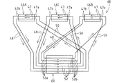
(1)図4は、参考例1の冷却装置60の概略図である。参考例1の冷却装置60は、複数(3基)の二次熱交換部46A,46B,46Cと、この二次熱交換部46A,46B,46Cと同数(3基)の蒸発器EP1,EP2,EP3を備えている。また、各二次熱交換部46A,46B,46Cには、凝縮経路47が1本ずつ設けられると共に、各蒸発器EP1,EP2,EP3には、蒸発管52が1本ずつ設けられている。参考例1の自然循環回路は、凝縮経路47の流出端47bに接続する液配管48を、当該凝縮経路47の流入端47aに連結したガス配管50が接続している蒸発管52と別の蒸発管52に接続すると共に、蒸発管52の流出端52bに接続するガス配管50を、当該蒸発管52の流入端52aに連結した液配管48が接続している凝縮経路47と別の凝縮経路47に接続して、全体として1つの回路として構成されている。ここで、参考例1の冷却装置60では、液化冷媒の供給を受けた凝縮経路47を有する二次熱交換部46とは別の二次熱交換部46の凝縮経路47へ各蒸発器EPの蒸発管52から気化冷媒を還流するよう構成される。また、参考例1の冷却装置60では、気化冷媒の供給を受けた蒸発管52を有する蒸発器EPとは別の蒸発器EPの蒸発管52へ各二次熱交換部46の凝縮経路47から液化冷媒を供給するようになっている。 (1) FIG. 4 is a schematic view of the cooling device 60 of Reference Example 1. The cooling device 60 of Reference Example 1 includes a plurality (three) of secondary heat exchange units 46A, 46B, 46C, and the same number (three) of evaporators EP1, EP2 as the secondary heat exchange units 46A, 46B, 46C. EP3 is provided. Each secondary heat exchange section 46A, 46B, 46C is provided with one condensing path 47, and each evaporator EP1, EP2, EP3 is provided with one evaporating pipe 52. In the natural circulation circuit of the reference example 1, the liquid pipe 48 connected to the outflow end 47b of the condensation path 47 is separated from the evaporation pipe 52 connected to the gas pipe 50 connected to the inflow end 47a of the condensation path 47. The gas pipe 50 connected to the pipe 52 and connected to the outflow end 52b of the evaporation pipe 52 is connected to the condensation pipe 47 connected to the liquid pipe 48 connected to the inflow end 52a of the evaporation pipe 52. Are connected as a whole and configured as one circuit. Here, in the cooling device 60 of Reference Example 1, each evaporator EP is supplied to the condensation path 47 of the secondary heat exchange unit 46 different from the secondary heat exchange unit 46 having the condensation path 47 that has been supplied with the liquefied refrigerant. The vaporized refrigerant is recirculated from the evaporation pipe 52. Further, in the cooling device 60 of Reference Example 1, from the condensation path 47 of each secondary heat exchange section 46 to the evaporation pipe 52 of the evaporator EP different from the evaporator EP having the evaporation pipe 52 that has been supplied with the vaporized refrigerant. A liquefied refrigerant is supplied.

参考例1の冷却装置60によれば、前提例2で説明した前述の作用効果と同様の作用効果を示す。また、二次熱交換部46および蒸発器EPを複数備えていても、凝縮経路47と蒸発管52とが1対1の関係で液配管48およびガス配管50で接続され、自然循環回路全体に対する各液配管48および各ガス配管50の寸法が短くなり、各液配管48および各ガス配管50における冷媒の流通抵抗が減少するので、圧力損失を小さくすることができる。 According to the cooling device 60 of the reference example 1, the same operation effect as the above-described operation effect described in the premise example 2 is shown. Even if a plurality of secondary heat exchange units 46 and evaporators EP are provided, the condensation path 47 and the evaporation pipe 52 are connected by the liquid pipe 48 and the gas pipe 50 in a one-to-one relationship, and the whole natural circulation circuit is connected. Since the dimensions of each liquid pipe 48 and each gas pipe 50 are shortened and the flow resistance of the refrigerant in each liquid pipe 48 and each gas pipe 50 is reduced, the pressure loss can be reduced.

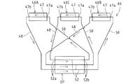
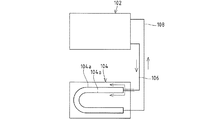
(2)図5は、参考例2の冷却装置62の概略図である。参考例2の冷却装置62は、1基の二次熱交換部46と、複数(3基)の蒸発器EP1,EP2,EP3を備えている。また、各蒸発器EP1,EP2,EP3には、蒸発管52が1本ずつ設けられると共に、二次熱交換部46には、蒸発管52の総数と同数の凝縮経路47が設けられている。参考例2の自然循環回路は、凝縮経路47の流出端47bに接続する液配管48を、当該凝縮経路47の流入端47aに連結したガス配管50が接続している蒸発管52と別の蒸発管52に接続すると共に、蒸発管52の流出端52bに接続するガス配管50を、当該蒸発管52の流入端52aに連結した液配管48が接続している凝縮経路47と別の凝縮経路47に接続して、全体として1つの回路として構成されている。ここで、参考例2の冷却装置62では、気化冷媒の供給を受けた蒸発管52を有する蒸発器EPとは別の蒸発器EPの蒸発管52へ二次熱交換部46の各凝縮経路47から液化冷媒を供給するようになっている。 (2) FIG. 5 is a schematic diagram of the cooling device 62 of Reference Example 2. The cooling device 62 of Reference Example 2 includes one secondary heat exchange unit 46 and a plurality (three) of evaporators EP1, EP2, and EP3. Each evaporator EP1, EP2, EP3 is provided with one evaporation pipe 52, and the secondary heat exchange section 46 is provided with the same number of condensation paths 47 as the total number of evaporation pipes 52. In the natural circulation circuit of Reference Example 2, the liquid pipe 48 connected to the outflow end 47b of the condensation path 47 is separated from the evaporation pipe 52 to which the gas pipe 50 connected to the inflow end 47a of the condensation path 47 is connected. The gas pipe 50 connected to the pipe 52 and connected to the outflow end 52b of the evaporation pipe 52 is connected to the condensation pipe 47 connected to the liquid pipe 48 connected to the inflow end 52a of the evaporation pipe 52. Are connected as a whole and configured as one circuit. Here, in the cooling device 62 of Reference Example 2, each condensation path 47 of the secondary heat exchange unit 46 is transferred to the evaporation pipe 52 of the evaporator EP different from the evaporator EP having the evaporation pipe 52 that has been supplied with the vaporized refrigerant. The liquefied refrigerant is supplied from the tank.

参考例2の冷却装置62によれば、前提例2で説明した前述の作用効果と同様の作用効果を示す。また、複数の蒸発器EPを設けても、各蒸発器EPの蒸発管52に供給される液化冷媒の量が一致しているから、複数の蒸発器EPによって別々の対象をバランスよく冷却することができる。なお、複数の蒸発器EPに設ける蒸発管52は1本に限られず、図6に示す参考例3の冷却装置64の如く、2本以上の複数本としても、蒸発器EP毎に本数を異ならしてもよい。 According to the cooling device 62 of the reference example 2, the same operation effect as the above-described operation effect described in the premise example 2 is shown. Even if a plurality of evaporators EP are provided, the amounts of liquefied refrigerant supplied to the evaporation pipes 52 of the respective evaporators EP are the same, so that different objects can be cooled in a balanced manner by the plurality of evaporators EP. Can do. Note that the number of the evaporator tubes 52 provided in the plurality of evaporators EP is not limited to one, and the number of the evaporators EP may be different for each evaporator EP even if two or more are provided as in the cooling device 64 of Reference Example 3 shown in FIG. May be.

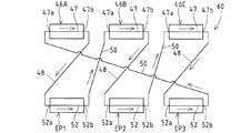
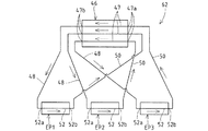
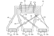
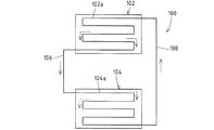
(3)図7は、前提例3の冷却装置66の概略図である。なお、前提例3の冷却装置では、1つの自然循環回路を備える構成であるが、前提例3の冷却装置における自然循環回路を独立して複数備えるように変更した構成が、本発明に係る冷却装置の実施例である。前記冷却装置66は、複数(3基)の二次熱交換部46A,46B,46Cと、1基の蒸発器EPを備えている。また、各二次熱交換部46A,46B,46Cには、凝縮経路47が1本ずつ設けられると共に、蒸発器EPには、凝縮経路47の総数と同数(3本)の蒸発管52が設けられている。前提例3の自然循環回路は、凝縮経路47の流出端47bに接続する液配管48を、当該凝縮経路47の流入端47aに連結したガス配管50が接続している蒸発管52と別の蒸発管52に接続すると共に、蒸発管52の流出端52bに接続するガス配管50を、当該蒸発管52の流入端52aに連結した液配管48が接続している凝縮経路47と別の凝縮経路47に接続して、全体として1つの回路として構成されている。ここで、前提例3の冷却装置66では、液化冷媒の供給を受けた凝縮経路47を有する二次熱交換部46とは別の二次熱交換部46の凝縮経路47へ蒸発器EPの各蒸発管52から気化冷媒を還流するよう構成される。 (3) FIG. 7 is a schematic diagram of the cooling device 66 of the third example . Note that the cooling device of the precondition example 3 has a configuration including one natural circulation circuit, but the configuration in which the cooling device of the premise example 3 is provided with a plurality of natural circulation circuits independently is the cooling device according to the present invention. It is the Example of an apparatus. The cooling device 66 includes a plurality (three) of secondary heat exchange units 46A, 46B, 46C and one evaporator EP. Each secondary heat exchange section 46A, 46B, 46C is provided with one condensation path 47, and the evaporator EP is provided with the same number (three) of evaporation pipes 52 as the total number of condensation paths 47. It has been. In the natural circulation circuit of the precondition example 3 , the liquid pipe 48 connected to the outflow end 47b of the condensing path 47 is separated from the evaporation pipe 52 connected to the gas pipe 50 connected to the inflow end 47a of the condensing path 47. The gas pipe 50 connected to the pipe 52 and connected to the outflow end 52b of the evaporation pipe 52 is connected to the condensation pipe 47 connected to the liquid pipe 48 connected to the inflow end 52a of the evaporation pipe 52. Are connected as a whole and configured as one circuit. Here, in the cooling device 66 of the precondition example 3 , each of the evaporators EP is transferred to the condensation path 47 of the secondary heat exchange unit 46 different from the secondary heat exchange unit 46 having the condensation path 47 that is supplied with the liquefied refrigerant. The vaporized refrigerant is recirculated from the evaporation pipe 52.

前提例3の冷却装置66によれば、前提例2で説明した前述の作用効果と同様の作用効果を示す。また、複数の二次熱交換部46を設けても、各二次熱交換部46の凝縮経路47に循環する気化冷媒の量が一致しているから、冷媒が偏在することを回避して、蒸発器EPにおいて対象を効率よく冷却することができる。なお、複数の二次熱交換部46に設ける凝縮経路47は1本に限られず、図8に示如く、2本以上の複数本としても、二次熱交換部46毎に本数を異ならしてもよい。 According to the cooling device 66 of the precondition example 3 , the same operation effect as the above-described operation effect described in the precondition example 2 is exhibited. Even if a plurality of secondary heat exchange units 46 are provided, the amount of vaporized refrigerant that circulates in the condensation path 47 of each secondary heat exchange unit 46 matches, so that the refrigerant is avoided from being unevenly distributed, The object can be efficiently cooled in the evaporator EP. Incidentally, the condensation path 47 provided on a plurality of secondary heat exchanging part 46 is not limited to one, as is shown in Fig 8, even a plurality of two or more, Shi different number for each secondary heat exchanging part 46 May be.

(イ)本発明の冷却装置は、空調設備等の冷却装置にも適用可能である。
(ロ)蒸発器は、箱体の内部を壁で区切ることで冷媒経路を形成したタイプの蒸発器であってもよい。
(ハ)本発明の冷却装置は、冷凍庫、冷凍・冷蔵庫、ショーケースおよびプレハブ庫等の所謂貯蔵庫に対しても適用し得る
()熱交換器は、一次熱交換部と二次熱交換部とを別体で構成したり、他の方式の熱交換器であってもよい。
()実施例では、一次冷却装置において液化冷媒を減圧する手段として膨張弁を用いたが、これに限られず、キャピラリーチューブまたはその他の減圧手段を採用し得る。
()実施例では、二次ループ式冷凍回路を備える冷却設備の二次側に本発明に係る冷却装置を用いる例を挙げている。前述の如く、二次ループ式冷凍回路を備えた冷却設備の欠点を解消し得ることから、本発明に係る冷却装置を二次ループ式冷凍回路に適用することは非常に有用である
()前提例1の冷却装置において、1つの熱交換部に対して複数の蒸発器を設けてもよい。すなわち、複数の冷媒循環回路の各凝縮経路が1つの熱交換部に設けられると共に、各蒸発器に対応の冷媒循環回路の蒸発経路が設けられる。また前提例1の冷却装置において、複数の熱交換部に対して1つの蒸発器を設けてもよい。すなわち、複数の冷媒循環回路の各蒸発経路が1つの蒸発器に設けられると共に、各熱交換部に対応の冷媒循環回路の凝縮経路が設けられる。
(B) The cooling device of the present invention can also be applied to cooling devices such as air conditioning equipment.
(B) The evaporator may be a type of evaporator in which a refrigerant path is formed by dividing the inside of the box with a wall.
(C) The cooling device of the present invention can also be applied to so-called storages such as a freezer, a freezer / refrigerator, a showcase, and a prefabricated store .
( D ) The heat exchanger may be configured such that the primary heat exchange unit and the secondary heat exchange unit are separated from each other, or may be a heat exchanger of another type.
( E ) In the embodiment, the expansion valve is used as means for reducing the pressure of the liquefied refrigerant in the primary cooling device. However, the present invention is not limited to this, and a capillary tube or other pressure reducing means may be employed.
( F ) In the embodiment, an example is given in which the cooling device according to the present invention is used on the secondary side of a cooling facility including a secondary loop refrigeration circuit. As described above, it is possible to eliminate the disadvantages of the cooling equipment provided with the secondary loop type refrigeration circuit . Therefore, it is very useful to apply the cooling device according to the present invention to the secondary loop type refrigeration circuit .
( G ) In the cooling device of Premise Example 1, a plurality of evaporators may be provided for one heat exchange unit. That is, each condensation path of a plurality of refrigerant circulation circuits is provided in one heat exchange unit, and an evaporation path of a refrigerant circulation circuit corresponding to each evaporator is provided. Moreover, in the cooling apparatus of the example 1 of an assumption , you may provide one evaporator with respect to a some heat exchange part. That is, each evaporation path of the plurality of refrigerant circulation circuits is provided in one evaporator, and a condensation path of the refrigerant circulation circuit corresponding to each heat exchange unit is provided.

本発明の実施例の前提となる前提例1に係る冷却装置を冷却設備の二次回路として備えた冷蔵庫を示す側断面図である。It is a sectional side view which shows the refrigerator provided with the cooling device which concerns on the example 1 used as the premise of the Example of this invention as a secondary circuit of cooling equipment. 本発明の実施例の前提となる前提例1に係る冷却装置を二次回路として備えた冷却設備の要部を示す概略回路図である。It is a schematic circuit diagram which shows the principal part of the cooling equipment provided with the cooling device which concerns on the premise example 1 used as the premise of the Example of this invention as a secondary circuit. 本発明の実施例の前提となる前提例2に係る冷却装置を二次回路として備えた冷却設備の要部を示す概略回路図である。It is a schematic circuit diagram which shows the principal part of the cooling equipment provided with the cooling device which concerns on the example 2 of assumption used as the premise of the Example of this invention as a secondary circuit. 参考例1の冷却装置を示す概略回路図である。 5 is a schematic circuit diagram showing a cooling device of Reference Example 1. FIG. 参考例2の冷却装置を示す概略回路図である。 10 is a schematic circuit diagram showing a cooling device of Reference Example 2. FIG. 参考例3の冷却装置を示す概略回路図である。It is a schematic circuit diagram which shows the cooling device of the reference example 3. 実施例の前提となる前提例3の冷却装置を示す概略回路図である。It is a schematic circuit diagram which shows the cooling device of the example 3 of assumption used as the premise of an Example . 前提例3の冷却装置における変更例を示す概略回路図である。It is a schematic circuit diagram which shows the example of a change in the cooling device of the example 3 of a premise . 第1従来例の冷却装置を示す概略回路図である。It is a schematic circuit diagram which shows the cooling device of a 1st prior art example. 第2従来例の冷却装置を示す概略回路図である。It is a schematic circuit diagram which shows the cooling device of a 2nd prior art example. 第3従来例の冷却装置を示す概略回路図である。It is a schematic circuit diagram which shows the cooling device of a 3rd prior art example.

34 一次冷却装置(一次側の回路),45,72 自然循環回路,
46 二次熱交換部(熱交換部),47 凝縮経路,47b 流出端,47a 流入端,
48 液配管,50 ガス配管,52 蒸発管(蒸発経路),52a 流入端,
52b 流出端,EP 蒸発器
34 Primary cooling device (primary circuit), 45,72 Natural circulation circuit,
46 secondary heat exchange part (heat exchange part), 47 condensation path, 47b outflow end, 47a inflow end,
48 liquid piping, 50 gas piping, 52 evaporation pipe (evaporation path), 52a inflow end,
52b Outflow end, EP evaporator

Claims (2)

凝縮経路(47)に流通する気化冷媒を凝縮して液化冷媒とする熱交換部(46)と、この熱交換部(46)の下方に配置され、蒸発経路(52)に流通する液化冷媒を蒸発させて気化冷媒とする蒸発器(EP)とを有し、
液化冷媒を熱交換部(46)の凝縮経路(47)から蒸発器(EP)の蒸発経路(52)へ液配管(48)を介して流下させると共に、気化冷媒を蒸発器(EP)の蒸発経路(52)から熱交換部(46)の凝縮経路(47)へガス配管(50)を介して流通させる自然循環回路(45)を備え、該自然循環回路(45)が、冷媒を強制循環させる機械圧縮式の一次側の回路(34)に前記熱交換部(46)を介して熱的に接続された冷却装置において、
数の前記熱交換部(46)に対して1つの前記蒸発器(EP)が設けられ、
複数の自然循環回路(45)を互いに独立するよう構成し、
互いに異なる自然循環回路(45)をなす前記蒸発経路(52)が前記蒸発器(EP)に設けられ
前記自然循環回路(45)は、前記蒸発器(EP)に設けられる複数の蒸発経路(52)と、前記複数の熱交換部(46)に振り分けて設けられ、前記複数の蒸発経路(52)と同数の凝縮経路(47)とを備え、
前記凝縮経路(47)の流出端(47b)に接続する液配管(48)を、当該凝縮経路(47)の流入端(47a)に連結したガス配管(50)が接続している蒸発経路(52)と別の蒸発経路(52)に接続すると共に、蒸発経路(52)の流出端(52b)に接続するガス配管(50)を、当該蒸発経路(52)の流入端(52a)に連結した液配管(48)が接続している凝縮経路(47)と別の凝縮経路(47)に接続して、1つの自然循環回路(45)を構成し
ことを特徴とする冷却装置。
A heat exchange section (46) that condenses the vaporized refrigerant flowing through the condensation path (47) to form a liquefied refrigerant, and a liquefied refrigerant that is disposed below the heat exchange section (46) and flows through the evaporation path (52). Having an evaporator (EP) that evaporates into a vaporized refrigerant,
The liquefied refrigerant is caused to flow down from the condensation path (47) of the heat exchange section (46) to the evaporation path (52) of the evaporator (EP) through the liquid pipe (48), and the vaporized refrigerant is evaporated in the evaporator (EP). comprising a path heat exchange unit from (52) gas pipe to the condensation path (46) (47) natural circulation circuit for circulating through the (50) (4 5), said natural circulation circuit (45), forcing the refrigerant In the cooling device thermally connected to the circuit (34) on the primary side of the mechanical compression type to be circulated through the heat exchange section (46),
The heat exchanging portion of the multiple one of said evaporator to (46) (EP) is provided,
A plurality of natural circulation circuits (4 5 ) are configured to be independent from each other,
The evaporation path (52) is provided in the evaporator (EP) constituting different natural circulation circuit (4 5) with one another,
The natural circulation circuit (45) is distributed to a plurality of evaporation paths (52) provided in the evaporator (EP) and the plurality of heat exchange sections (46), and the plurality of evaporation paths (52). And the same number of condensation paths (47),
The liquid pipe (48) connected to the outflow end (47b) of the condensation path (47) is connected to the gas pipe (50) connected to the inflow end (47a) of the condensation path (47) (evaporation path ( 52) is connected to another evaporation path (52), and the gas pipe (50) connected to the outflow end (52b) of the evaporation path (52) is connected to the inflow end (52a) of the evaporation path (52). A cooling apparatus characterized in that one natural circulation circuit (45) is configured by connecting to a condensation path (47) to which the liquid pipe (48) connected is connected to another condensation path (47) .
前記蒸発経路(52)が直線状に形成された請求項記載の冷却装置。 The evaporation path (52) a cooling device according to claim 1, wherein the linearly formed.
JP2007327771A 2007-12-19 2007-12-19 Cooling system Expired - Fee Related JP5405015B2 (en)

Priority Applications (7)

Application Number Priority Date Filing Date Title
JP2007327771A JP5405015B2 (en) 2007-12-19 2007-12-19 Cooling system
PCT/JP2008/069049 WO2009078218A1 (en) 2007-12-19 2008-10-21 Cooling device
US12/735,130 US20110232873A1 (en) 2007-12-19 2008-10-21 Cooling device
EP08862712.0A EP2233861B1 (en) 2007-12-19 2008-10-21 Cooling device
AU2008336946A AU2008336946B2 (en) 2007-12-19 2008-10-21 Cooling device
CN2008801217507A CN101903712A (en) 2007-12-19 2008-10-21 Cooling device
TW097142327A TWI420063B (en) 2007-12-19 2008-11-03 Cooling apparatus

Applications Claiming Priority (1)

Application Number Priority Date Filing Date Title
JP2007327771A JP5405015B2 (en) 2007-12-19 2007-12-19 Cooling system

Publications (2)

Publication Number Publication Date
JP2009150588A JP2009150588A (en) 2009-07-09
JP5405015B2 true JP5405015B2 (en) 2014-02-05

Family

ID=40795337

Family Applications (1)

Application Number Title Priority Date Filing Date
JP2007327771A Expired - Fee Related JP5405015B2 (en) 2007-12-19 2007-12-19 Cooling system

Country Status (7)

Country Link
US (1) US20110232873A1 (en)
EP (1) EP2233861B1 (en)
JP (1) JP5405015B2 (en)
CN (1) CN101903712A (en)
AU (1) AU2008336946B2 (en)
TW (1) TWI420063B (en)
WO (1) WO2009078218A1 (en)

Families Citing this family (11)

* Cited by examiner, † Cited by third party
Publication number Priority date Publication date Assignee Title
CN102813272A (en) * 2012-09-11 2012-12-12 天津中局科技发展有限公司 Raw milk quick-cooling device
WO2014132592A1 (en) * 2013-02-26 2014-09-04 日本電気株式会社 Electronic apparatus cooling system and electronic apparatus cooling system fabrication method
JP6528844B2 (en) * 2015-07-08 2019-06-12 株式会社デンソー Refrigeration system and in-vehicle refrigeration system
US10260819B2 (en) * 2016-07-26 2019-04-16 Tokitae Llc Thermosiphons for use with temperature-regulated storage devices
US11255611B2 (en) * 2016-08-02 2022-02-22 Munters Corporation Active/passive cooling system
US11839062B2 (en) * 2016-08-02 2023-12-05 Munters Corporation Active/passive cooling system
CN109716051B (en) * 2016-10-06 2020-06-12 株式会社电装 Equipment temperature adjusting device
US11287172B2 (en) 2018-01-29 2022-03-29 Tippmann Companies Llc Freezer dehumidification system
KR102193565B1 (en) * 2019-07-24 2020-12-21 서선기 Heating and cooling system using buoyancy and water pressure of high-rise building
US20220235982A1 (en) * 2019-08-07 2022-07-28 Mitsubishi Electric Corporation Refrigeration cycle apparatus
CN117239943B (en) * 2023-11-14 2024-03-08 百穰新能源科技(深圳)有限公司 Energy storage system

Family Cites Families (12)

* Cited by examiner, † Cited by third party
Publication number Priority date Publication date Assignee Title
JPS6071895A (en) * 1983-09-28 1985-04-23 Hitachi Ltd Heat transmitting device
JP3119995B2 (en) * 1994-05-11 2000-12-25 アクトロニクス株式会社 Cooling structure for static induction equipment windings
US5490390A (en) * 1994-05-13 1996-02-13 Ppg Industries, Inc. Liquefaction of chlorine or other substances
JP3543448B2 (en) * 1995-11-13 2004-07-14 ダイキン工業株式会社 Heat transfer device
JPH10238972A (en) * 1997-02-24 1998-09-11 Hitachi Ltd Heat transfer unit
JPH11257720A (en) * 1998-03-10 1999-09-24 Takenaka Komuten Co Ltd Building frame regenerative air conditioning system
US6619066B1 (en) * 1999-02-24 2003-09-16 Hachiyo Engineering Co., Ltd. Heat pump system of combination of ammonia cycle carbon dioxide cycle
JP4086575B2 (en) 2002-07-26 2008-05-14 三洋電機株式会社 Heat transfer device and operation method thereof
US6871509B2 (en) * 2002-10-02 2005-03-29 Carrier Corporation Enhanced cooling system
JP2005283022A (en) 2004-03-30 2005-10-13 Sharp Corp Evaporator, thermosiphon, and stirling cooler
JP4358759B2 (en) * 2005-02-10 2009-11-04 三菱電機株式会社 Natural circulation cooling device control method and natural circulation cooling device
JP5275929B2 (en) * 2008-08-26 2013-08-28 ホシザキ電機株式会社 Cooling system

Also Published As

Publication number Publication date
CN101903712A (en) 2010-12-01
AU2008336946B2 (en) 2012-12-13
EP2233861A1 (en) 2010-09-29
EP2233861A4 (en) 2012-08-22
JP2009150588A (en) 2009-07-09
AU2008336946A1 (en) 2009-06-25
TWI420063B (en) 2013-12-21
TW200936970A (en) 2009-09-01
EP2233861B1 (en) 2016-05-18
US20110232873A1 (en) 2011-09-29
WO2009078218A1 (en) 2009-06-25

Similar Documents

Publication Publication Date Title
JP5405015B2 (en) Cooling system
JP5275929B2 (en) Cooling system
JPWO2015093234A1 (en) Refrigeration system defrost system and cooling unit
JP2005337700A (en) Refrigerant cooling circuit
JP2007183044A (en) Cooling apparatus and vending machine
JP4945713B2 (en) Cooling system
JP4945712B2 (en) Thermosiphon
JP4835196B2 (en) Cooling unit and vending machine
JP5405058B2 (en) Cooling system
JP2007178081A (en) Refrigerator
JP2007309536A (en) Refrigerating device
JP4274074B2 (en) Refrigerator and vending machine
JP2004333092A (en) Freezer/refrigerator
JP2004326400A (en) Vending machine
JP5056026B2 (en) vending machine
JP2007102680A (en) Automatic vending machine
WO2009157318A1 (en) Cooling device
JP2017020675A (en) Refrigeration cycle device
KR101444372B1 (en) Heat exchanger system of cooling and heating
JP2012242078A (en) Electric refrigerator
JP2009140308A (en) Vending machine
JP2008057974A (en) Cooling apparatus
JP2016142483A (en) Air cooler
JP6229955B2 (en) Refrigeration apparatus and defrost method for load cooler
JP2023083192A (en) Cooling device

Legal Events

Date Code Title Description
A621 Written request for application examination

Free format text: JAPANESE INTERMEDIATE CODE: A621

Effective date: 20101115

A131 Notification of reasons for refusal

Free format text: JAPANESE INTERMEDIATE CODE: A131

Effective date: 20120424

A521 Written amendment

Free format text: JAPANESE INTERMEDIATE CODE: A523

Effective date: 20120621

A131 Notification of reasons for refusal

Free format text: JAPANESE INTERMEDIATE CODE: A131

Effective date: 20130108

A521 Written amendment

Free format text: JAPANESE INTERMEDIATE CODE: A523

Effective date: 20130305

A01 Written decision to grant a patent or to grant a registration (utility model)

Free format text: JAPANESE INTERMEDIATE CODE: A01

Effective date: 20131001

A61 First payment of annual fees (during grant procedure)

Free format text: JAPANESE INTERMEDIATE CODE: A61

Effective date: 20131030

S533 Written request for registration of change of name

Free format text: JAPANESE INTERMEDIATE CODE: R313533

R350 Written notification of registration of transfer

Free format text: JAPANESE INTERMEDIATE CODE: R350

LAPS Cancellation because of no payment of annual fees