JP5402618B2 - Recording head control method and dot impact printer - Google Patents
Recording head control method and dot impact printer Download PDFInfo
- Publication number
- JP5402618B2 JP5402618B2 JP2009294060A JP2009294060A JP5402618B2 JP 5402618 B2 JP5402618 B2 JP 5402618B2 JP 2009294060 A JP2009294060 A JP 2009294060A JP 2009294060 A JP2009294060 A JP 2009294060A JP 5402618 B2 JP5402618 B2 JP 5402618B2
- Authority
- JP
- Japan
- Prior art keywords
- dot
- printing
- recording head
- temperature
- recording
- Prior art date
- Legal status (The legal status is an assumption and is not a legal conclusion. Google has not performed a legal analysis and makes no representation as to the accuracy of the status listed.)
- Expired - Fee Related
Links
Images


Description
本発明は、記録ヘッドに搭載した記録ワイヤを駆動して印刷ドット列を形成するドットインパクトプリンターにおける記録ヘッドの制御方法およびドットインパクトプリンターに関し、特に、印刷時の発熱によるヘッドコイルの焼損を防止しつつ、必要以上の印刷スループットの低下を抑制できる記録ヘッドの制御方法およびドットインパクトプリンターに関する。 The present invention relates to a recording head control method and a dot impact printer in a dot impact printer that drives a recording wire mounted on a recording head to form a print dot array, and in particular, prevents burning of a head coil due to heat generation during printing. The present invention also relates to a recording head control method and a dot impact printer that can suppress a decrease in printing throughput more than necessary.
この種のドットインパクトプリンターは、キャリッジに記録ヘッドを搭載して、キャリッジを記録紙の紙幅方向に走査しながら記録ヘッドの記録ワイヤを駆動して、1ドットラインずつ印刷を行っている。記録ヘッドには、複数の記録ワイヤが配列されており、印刷データに基づいて、記録ヘッドを移動させながら必要なタイミングで必要な記録ワイヤを駆動することにより、記録紙上の必要な位置にドットを形成して印刷を行うことができる。 In this type of dot impact printer, a recording head is mounted on a carriage, and the recording wire of the recording head is driven while scanning the carriage in the paper width direction of the recording paper to perform printing one dot line at a time. A plurality of recording wires are arranged on the recording head. By moving the recording head at the required timing while moving the recording head based on the print data, dots are formed at the required positions on the recording paper. It can be formed and printed.
ドットインパクトプリンターにおいては、記録ワイヤが連続して駆動されると、この記録ワイヤを駆動しているヘッドコイル(駆動コイル)が急激に温度上昇して焼損するおそれがある。そこで、ヘッドコイルの焼損を防止するために、サーミスターによって記録ヘッドの温度を検出して、焼損のおそれがある温度になったときにはヘッドコイルの発熱量を減少させる制御を行っている。特許文献1には、このような制御を行うドットインパクトプリンターが記載されている。特許文献1のドットインパクトプリンターは、記録ヘッドの温度が予め設定したスピードダウン設定温度に至ったときには、ヘッドコイルの駆動周波数を減少させて印刷速度を減速させる。また、記録ヘッドの温度が予め設定した停止設定温度に至ったときには、その時点で記録ヘッドによる印刷動作を停止させて、ヘッドコイルが焼損限界温度に到達しないようにしている。
In the dot impact printer, when the recording wire is continuously driven, the head coil (driving coil) that drives the recording wire may rapidly increase in temperature and burn out. Therefore, in order to prevent burning of the head coil, the temperature of the recording head is detected by a thermistor, and control is performed to reduce the amount of heat generated by the head coil when the temperature reaches a temperature at which burning is likely to occur.
ヘッドコイルの温度が急激に上昇するときには、ヘッドコイルが予め設定した温度になったことをサーミスターによって検出して減速や停止などの処理を実行する前にヘッドコイルが焼損限界温度を越えてしまい、焼損を防止できないことがある。特許文献1のドットインパクトプリンターにおいては、このような事態を防止するために、予め、急激な温度上昇を引き起こすことが予測される特定のドットパターン(特定記録パターン)が設定されている。そして、印刷データの中にこの特定記録パターンを検出したときには、スピードダウン設定温度や停止設定温度を通常よりも低く設定して印刷を行う。これにより、ヘッドコイルの温度が急激に上昇する場合においても、ヘッドコイルが焼損限界温度に到達する前に印刷動作の減速や停止を行うことができる。よって、ヘッドコイルの焼損をより確実に防止することができる。
When the temperature of the head coil suddenly rises, the head coil exceeds the burnout limit temperature before detecting that the head coil has reached a preset temperature by the thermistor and executing processing such as deceleration or stop. Burnout may not be prevented. In the dot impact printer of
ここで、特許文献1では、特定記録パターンを1箇所でも検出した場合には、スピードダウン設定温度や停止設定温度を低い温度に変更している。しかしながら、このような構成では、例えば、記録ヘッドの温度が十分低い状態で特定記録パターンの印刷が行われた場合などには、特定記録パターンを印刷しても焼損限界温度に到達しないにもかかわらず、そのような場合であっても、印刷速度が減速されたり、印刷動作の停止が行われてしまう場合がある。つまり、特許文献1の構成では、減速や停止が必要でない場合にまで減速や停止が行われてしまい、必要以上に印刷スループットが低下するという問題点がある。
Here, in
本発明の課題は、この点に鑑みて、印刷時の発熱によるヘッドコイルの焼損を確実に防止しつつ、必要以上の印刷スループットの低下を抑制できる記録ヘッドの制御方法およびドットインパクトプリンターを提案することにある。 In view of this point, an object of the present invention is to propose a recording head control method and a dot impact printer capable of suppressing a decrease in print throughput more than necessary while reliably preventing head coil burnout due to heat generation during printing. There is.
上記の課題を解決するために、本発明は、
複数の記録ワイヤを有する記録ヘッドが搭載されたキャリッジを走査しながら、前記記録ワイヤを駆動して、記録媒体に情報を印刷するドットインパクトプリンターにおける記録ヘッドの制御方法であって、
各々の前記記録ワイヤは、キャリッジの走査方向における1ドットラインの印刷を担当しており、
前記ドットラインの最大ライン長の領域内に、所定幅のパターン検出領域を予め複数設定しておき、
前記ドットラインの印刷において、
印刷実行前に、印刷対象の前記ドットラインにおける前記パターン検出領域が、予め設定した特定のドットパターンを含む特定領域であるか否かを判定し、
前記特定領域であると判定された場合、前記印刷対象の前記ドットラインにおける前記特定領域の数が2以上の基準数以上であるか否かを判定し、
その判定結果に基づいて、前記ドットラインを印刷することを特徴としている。
また、本発明では、前記判定結果に基づいて、前記ドットラインを印刷するための前記記録ヘッドの駆動モードを決定することを特徴としている。
In order to solve the above problems, the present invention provides:
A method for controlling a recording head in a dot impact printer for printing information on a recording medium by driving the recording wire while scanning a carriage on which a recording head having a plurality of recording wires is mounted,
Each recording wire is in charge of printing one dot line in the scanning direction of the carriage,
In the area of the maximum line length of the dot line, a plurality of pattern detection areas of a predetermined width are set in advance,
In printing the dot line,
Before printing, it is determined whether the pattern detection area in the dot line to be printed is a specific area including a specific dot pattern set in advance,
Wherein when it is determined that the specific region, the number of the specific area in the dot line of the print target to determine der Luke not more than the reference number,
Based on the determination result, it is characterized that you printing the dot line.
In the present invention, a drive mode of the recording head for printing the dot line is determined based on the determination result.
本発明では、このような構成により、特定のドットパターンとして記録ヘッドの急激な温度上昇を引き起こすものを設定しておくことにより、記録ヘッドの温度が1ドットラインを印刷する間の複数の位置において急激に上昇し、このため、記録ヘッドの温度がヘッドコイルの焼損限界温度を越えるおそれがある場合に、焼損を引き起こさないようにすることができる。 In the present invention, with such a configuration, a specific dot pattern that causes a rapid rise in the temperature of the recording head is set, so that the temperature of the recording head can be set at a plurality of positions while printing one dot line. rapidly increases, Accordingly, if the temperature of the recording head is likely to exceed the burnout threshold temperature of the head coil, it is possible not to cause burnout.
また、本発明では、特定のドットパターンの判定結果に基づいて、ドットラインを印刷するための記録ヘッドの駆動モードを決定することを特徴としており、これにより、記録ヘッドの温度がヘッドコイルの焼損限界温度を越えるおそれがある場合に、焼損を引き起こさない駆動モードで印刷を実行することができる。一方、記録ヘッドの急激な温度上昇は発生するものの、このような温度上昇が1ドットライン中において予め設定した数未満の場所でしか起こらないために、記録ヘッドの温度がヘッドコイルの焼損限界温度を越えないと想定される場合には、駆動モードの変更を行わないようにすることができる。よって、ヘッドコイルの焼損を確実に防止しつつ、必要以上の印刷スループットの低下を抑制できる。
Further, in the present invention, based on the determination result of the particular dot pattern, and the determining means determines the driving mode of the recording head for printing dots line, thereby, burnout temperature of the recording head of the head coil When there is a risk of exceeding the limit temperature, printing can be executed in a driving mode that does not cause burning. On the other hand, although a rapid temperature rise of the recording head occurs, such a temperature rise occurs only in a place less than a preset number in one dot line, so the temperature of the recording head is the burnout limit temperature of the head coil. In the case where it is assumed that the value does not exceed the drive mode, it is possible not to change the drive mode. Therefore, it is possible to suppress the deterioration of the print throughput more than necessary while reliably preventing the head coil from burning.
本発明において、予め、1ドットラインの最大ライン長の領域内に、所定幅のパターン検出領域を複数設定しておき、各ドットラインの印刷において、印刷実行前に、印刷対象のドットラインにおける各パターン検出領域が、前記特定のドットパターンを含む特定領域であるか否かを判定し、当該ドットラインにおける前記特定領域の数が前記基準数以上であるか否かを判定し、当該判定結果に基づいて、当該ドットラインを印刷するための前記記録ヘッドの駆動モードを決定することもできる。このような構成では、各ドットラインのデータ全体を特定のドットパターンと対比する場合と比較して、処理負荷を軽減することができる。 In the present invention, a plurality of pattern detection areas having a predetermined width are set in advance in the area of the maximum line length of one dot line, and each dot line in the print target dot line is printed before printing. It is determined whether a pattern detection area is a specific area including the specific dot pattern, whether the number of the specific areas in the dot line is equal to or greater than the reference number, and the determination result Based on this, it is possible to determine the drive mode of the recording head for printing the dot line. In such a configuration, the processing load can be reduced as compared with the case where the entire data of each dot line is compared with a specific dot pattern.
また、本発明において、予め、印刷時の前記記録ヘッドの駆動モードとして、発熱量が異なる複数の駆動モード設定しておくと共に、各駆動モードと前記記録ヘッドの温度とを対応付けておき、前記各駆動モードに対応付けられている前記記録ヘッドの温度は、第1温度と、当該第1温度よりも低い第2温度の少なくとも2つの温度を含み、各ドットラインの印刷において、印刷実行前に、前記記録ヘッドの温度を検出し、印刷対象のドットラインにおける前記特定領域の数が前記基準数以上であった場合には、前記第2温度を用いて、検出した前記記録ヘッドの温度に対応する前記駆動モードを選択し、当該ドットラインにおける前記特定領域の数が前記基準数未満であった場合には、前記第1温度を用いて、検出した前記記録ヘッドの温度に対応する前記駆動モードを選択し、当該選択した前記駆動モードにより、当該ドットラインの印刷を実行する構成とすることができる。このように、記録ヘッドの温度を複数設定しておけば、特定のドットパターンを含むパターン検出領域の数に基づいて2種類の温度を使い分けることにより、ヘッドコイルの焼損を確実に防止しつつ、必要以上の印刷スループットの低下を抑制できる。 In the present invention, a plurality of drive modes having different calorific values are set in advance as drive modes of the recording head at the time of printing, and each drive mode is associated with the temperature of the recording head, The temperature of the recording head associated with each drive mode includes at least two temperatures of a first temperature and a second temperature lower than the first temperature. The temperature of the recording head is detected, and when the number of the specific areas in the dot line to be printed is equal to or larger than the reference number, the second temperature is used to correspond to the detected temperature of the recording head. When the drive mode is selected and the number of the specific areas in the dot line is less than the reference number, the detected temperature of the recording head is detected using the first temperature. Selecting the driving mode corresponding to, by the selected said drive mode, it can be configured to perform printing of the dot line. As described above, if a plurality of recording head temperatures are set, the head coil can be reliably prevented from being burned out by properly using two types of temperatures based on the number of pattern detection areas including a specific dot pattern. A decrease in print throughput more than necessary can be suppressed.
このとき、印刷対象のドットラインの印刷実行前に検出した前記記録ヘッドの温度が予め設定した基準温度以下であった場合には、前記各パターン検出領域が前記特定領域であるか否かの判定結果を用いずに前記記録ヘッドの前記駆動モードを決定することが望ましい。このような構成によれば、複数のパターン検出領域で特定のドットパターンが印刷され、それでもなお焼損限界温度を超えないことが想定される場合にこのことを判別して、必要以上の印刷スループットの低下を抑制することができる。 At this time, if the temperature of the recording head detected before printing the dot line to be printed is equal to or lower than a preset reference temperature, it is determined whether or not each of the pattern detection areas is the specific area. It is desirable to determine the driving mode of the recording head without using the result. According to such a configuration, when a specific dot pattern is printed in a plurality of pattern detection areas and it is still assumed that the burnout limit temperature is not exceeded, this is determined, and an unnecessarily high print throughput is achieved. The decrease can be suppressed.
本発明において、印刷データの印刷品位と、前記記録ヘッドの駆動モードとを対応付けておき、各ドットラインの印刷において、印刷対象のドットラインを含む印刷データの印刷品位に対応付けられている前記駆動モードの中から決定した前記駆動モードにより、当該ドットラインの印刷を実行することが望ましい。ドットインパクトプリンターにおいては、印刷品位の設定に応じて記録ヘッドの駆動制御が異なるため、印刷品位によって温度上昇の度合いが異なる。そのため、印刷品位に対応づけて駆動モードを設定しておけば、ヘッドコイルの焼損防止と印刷スループットの低下抑制の両立をより適切に実現することができる。 In the present invention, the print quality of print data and the drive mode of the recording head are associated with each other, and in the printing of each dot line, the print quality of the print data including the dot line to be printed is associated with the print quality. It is desirable to execute the printing of the dot line in the drive mode determined from the drive modes. In a dot impact printer, since the drive control of the recording head differs depending on the print quality setting, the degree of temperature rise varies depending on the print quality. Therefore, if the drive mode is set in association with the print quality, it is possible to more appropriately realize both the prevention of head coil burnout and the suppression of the decrease in print throughput.
ここで、前記特定のドットパターンは、印刷時に同時に駆動される前記記録ワイヤの数、および、同一の記録ワイヤの連続駆動回数に基づいて設定することができる。すなわち、同時に駆動されている記録ワイヤの数が多く、且つ、連続駆動回数が多くドット密度が高ければ急激な温度上昇が発生するので、これらのパラメーターに基づいて、急激な温度上昇が発生する特定のドットパターンを設定できる。 Here, the specific dot pattern can be set based on the number of the recording wires that are simultaneously driven during printing and the number of continuous driving times of the same recording wire. In other words, if the number of recording wires that are driven simultaneously is large and the number of continuous drives is large and the dot density is high, a rapid temperature rise will occur. The dot pattern can be set.
次に、本発明は、
情報が印刷される記録媒体の送り方向と略直交する方向に走査されるキャリッジと、
前記キャリッジに搭載され、ドットライン中に印刷ドット列を形成する複数の記録ワイヤを有する記録ヘッドと、
前記記録ヘッドを制御する制御部と、を有し、
前記制御部は、前記ドットラインの最大ライン長の領域内に、所定幅のパターン検出領域を予め複数設定しておき、前記ドットラインの印刷において、印刷実行前に、印刷対象の前記ドットラインにおける前記パターン検出領域が、予め設定した特定のドットパターンを含む特定領域であるか否かを判定し、前記特定領域であると判定された場合、前記印刷対象の前記ドットラインにおける前記特定領域の数が2以上の基準数以上であるか否かを判定し、その判定結果に基づいて、前記ドットラインを印刷することを特徴とするドットインパクトプリンターである。また制御部は、前記判定結果に基づいて、前記ドットラインを印刷するための前記記録ヘッドの駆動モードを決定して、前記ドットラインを印刷することを特徴とする。
Next, the present invention
A carriage that is scanned in a direction substantially perpendicular to the feeding direction of the recording medium on which information is printed;
A recording head mounted on the carriage and having a plurality of recording wires forming a print dot row in a dot line;
A control unit for controlling the recording head,
The control unit sets in advance a plurality of pattern detection areas having a predetermined width within the area of the maximum line length of the dot lines, and in the printing of the dot lines, the dot lines to be printed are printed before printing. It is determined whether or not the pattern detection area is a specific area including a specific dot pattern that is set in advance. If it is determined that the specific area is the specific area, the pattern detection area of the specific area in the dot line to be printed number determines whether
本発明によれば、特定のドットパターンとして記録ヘッドの急激な温度上昇を引き起こすものを設定しておくことにより、記録ヘッドの温度が1ドットラインを印刷する間の複数の位置において急激に上昇し、このため、記録ヘッドの温度がヘッドコイルの焼損限界温度を越えるおそれがある場合に、焼損を引き起こさない駆動モードで印刷を実行することができる。一方で、記録ヘッドの急激な温度上昇は発生するものの、このような温度上昇が1ドットライン中において予め設定した数未満の場所でしか起こらないために、記録ヘッドの温度がヘッドコイルの焼損限界温度を越えないと想定される場合にまで、駆動モードの変更を行わないようにすることができる。よって、ヘッドコイルの焼損を確実に防止しつつ、必要以上の印刷スループットの低下を抑制できる。 According to the present invention, by setting a specific dot pattern that causes a rapid temperature increase of the recording head, the temperature of the recording head rapidly increases at a plurality of positions while printing one dot line. Therefore, when there is a possibility that the temperature of the recording head exceeds the burnout limit temperature of the head coil, printing can be executed in a drive mode that does not cause burnout. On the other hand, although a rapid temperature rise of the recording head occurs, such a temperature rise occurs only in a place less than a preset number in one dot line, so the temperature of the recording head is limited to the burnout limit of the head coil. It is possible not to change the drive mode until it is assumed that the temperature is not exceeded. Therefore, it is possible to suppress the deterioration of the print throughput more than necessary while reliably preventing the head coil from burning.
以下に、図面を参照して、本発明を適用したインパクトドットプリンターおよび記録ヘッドの制御方法の実施の形態を説明する。 Hereinafter, embodiments of an impact dot printer and a control method of a recording head to which the present invention is applied will be described with reference to the drawings.
(全体構成)
図1は、本実施形態のドットインパクトプリンターの主要部の概略構成図である。ドットインパクトプリンター1は、プリンターフレームの左右の側板2、3の間に横向きに延びているキャリッジガイド軸4を備えており、このキャリッジガイド軸4に沿って、記録ヘッド5を搭載したキャリッジ6が、タイミングベルトとプーリーなどの駆動機構6bを介して、キャリッジモーター6aの出力に基づいてプリンター幅方向に往復移動するように構成されている。記録ヘッド5にはプラテン7が一定のギャップで対峙している。プラテン7によって規定される印刷位置には、この印刷位置を経由する記録紙搬送経路に沿って記録紙が送り込まれる。記録紙は、記録ヘッド5による印刷動作と連動して、記録紙搬送機構13(図2参照)によって記録紙搬送経路に沿って搬送され、印刷が終了すると、プリンター外部に排出される。
(overall structure)
FIG. 1 is a schematic configuration diagram of a main part of the dot impact printer of the present embodiment. The
記録ヘッド5とプラテン7の隙間には、図示しないインクリボンカセットから引き出されたインクリボン8が、記録ヘッド5のヘッド面5aに沿って架け渡された状態となるように装着されている。インクリボン8は、図示しない巻取り軸によって、使用済み部分を順次巻き取り可能に構成されている。記録ヘッド5は、複数の記録ワイヤ9と、各記録ワイヤ9を駆動するためのソレノイドコイル等からなるヘッドコイル10(図2参照)を備えており、各記録ワイヤ9の先端が、対応するヘッドコイル10の駆動力によってヘッド面5aからプラテン7側に突出可能となるように構成されている。ヘッド面5aには、複数の記録ワイヤ9が、各記録ワイヤ9によって印刷データの1ドットを構成するように配列されている。例えば、24本の記録ワイヤ9をヘッド面5aにおいて12本ずつ2列に配列した構成とすることができる。
In the gap between the
ヘッドコイル10に通電が行われると、通電されたヘッドコイル10に対応する記録ワイヤ9がインクリボン8を介してプラテン7上の記録紙に打ち付けられる。これにより、記録紙にインクリボン8のインクによるドットが形成される。また、記録紙と感圧紙を重ねて搬送している場合には、感圧紙における同一の位置にもドットが形成される。ドットインパクトプリンター1は、キャリッジ6を走査しながら、印刷データに基づいて各ヘッドコイル10に通電し、各記録ワイヤ9を必要なタイミングで突出させることにより、1ドットラインずつ印刷を行う。1ドットラインの印刷が終了すると、1ドットライン分記録紙を搬送した後、次のドットラインの印刷を行う。
When the
(制御系)
図2は、ドットインパクトプリンターにおける印刷機構の制御系を示すブロック図である。ドットインパクトプリンター1の制御部11には、ホスト装置12から印刷データや制御コマンドなどが通信回線などを介して入力される。制御部11は、この印刷データや制御コマンドに基づいて、キャリッジモーター6aおよび記録紙搬送機構13に制御信号を出力して、記録紙の搬送位置およびキャリッジ6の位置を制御する。また、制御部11は、印刷データや制御コマンドなどに基づいて、記録ヘッド5の各ヘッドコイル10に図示しないヘッドドライバーを介して制御信号を出力し、各ヘッドコイルの通電状態を制御する。
(Control system)
FIG. 2 is a block diagram illustrating a control system of the printing mechanism in the dot impact printer. Print data and control commands are input from the
制御部11には、記録ヘッド5のフレームに設けられた温度検出器14の検出信号が入力される。制御部11は、印刷を行うときには、温度検出器14の検出信号に基づいて記録ヘッド5が予め設定した基準温度を越えたか否かを判定する。そして、この判定結果に基づいて、印刷時の記録ヘッド5の駆動モード、すなわち、各記録ワイヤ9を駆動するためのヘッドコイル10の通電制御に係る設定を決定する。制御部11には、このような駆動モードの決定、および、各駆動モードにおける制御に用いられるデータを記憶させておくための記憶部11aが設けられている。
A detection signal from a
(記録ヘッドの制御方法)
図3は、各ドットラインにおけるパターン検出領域の配置図である。本実施形態では、1ドットラインを最大136桁(1桁は、1文字分の幅)で構成しており、この1ドットラインの最大桁の領域内に、5箇所のパターン検出領域15を設定している。すなわち、136桁の左端と右端にそれぞれパターン検出領域15を設け、その中間に残り3箇所のパターン検出領域15が均等に配置されるように、各パターン検出領域15を配置している。各パターン検出領域の幅を8桁とした場合には、隣接するパターン検出領域15の間の非検出領域16の幅は24桁となる。
(Recording head control method)
FIG. 3 is a layout diagram of pattern detection areas in each dot line. In this embodiment, one dot line is composed of a maximum of 136 digits (one digit is the width of one character), and five
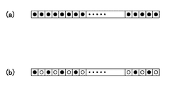
図4(a)(b)は、駆動モードの決定に用いる特殊ビットイメージ(特定のドットパターン)の説明図であり、図4(a)は同一の記録ワイヤ9により連続して50ドットが形成される第1ドットパターン、図4(b)は同一の記録ワイヤ9により連続した50ドット分の長さにおいて1ドットおきに25個のドットが形成される第2ドットパターンである。制御部11は、各ドットラインの印刷を行う前に、予め、印刷対象のドットラインにおける上記の5箇所のパターン検出領域15に、これらの第1ドットパターン、もしくは第2ドットパターンが含まれるか否かの判定を行う。そして、印刷対象のドットラインにおいて、第1ドットパターン、もしくは第2ドットパターンが含まれるパターン検出領域15(特定領域)の数がいくつあるかをカウントして、このカウント数が、予め設定した基準数N以上か、基準数N未満かを判定する。そして、この判定結果に基づいて、このドットラインを印刷するときの記録ヘッド5の駆動モードを決定している。なお、本実施形態では、基準数Nとして、2、3、4、5のいずれかの数を設定することができる。
4A and 4B are explanatory diagrams of a special bit image (specific dot pattern) used for determining the drive mode. FIG. 4A is a diagram in which 50 dots are continuously formed by the
また、本実施形態では、記録ヘッド5の駆動モードを決定するためのパラメーターとして、上述した特定領域の数の他に、印刷対象のドットラインを含む印刷データに対して指定される印刷品位の設定を用いている。印刷品位は、印刷モードと文字品位の2つのパラメーターの組合せによって指定されている。印刷モードとしては、「ノーマル」と「コピー」のいずれかのモードが指定されている。また、文字品位としては、「DRAFT」と、「LQ(Letter Quality)」のいずれかが指定されている。DRAFTモードは、予め設定した基準解像度よりも低い解像度の印刷データに対して指定され、LQモードは、基準解像度以上の解像度の印刷データに対して指定されている。
In the present embodiment, as a parameter for determining the drive mode of the
図5は、駆動モード決定用の制御テーブルである。上述したように、本実施形態では、温度検出器14の検出信号に基づいて記録ヘッド5が予め設定した基準温度を越えたか否かを判定し、この判定結果に基づいて、各ドットラインの印刷時の各ヘッドコイル10への通電内容を調整しているが、この基準温度として、3種類の基準温度を用いている。図5において、「特殊ビットイメージ」と表示している欄は、特定領域の数が基準数N以上の場合、「特殊ビットイメージ以外」と表示している欄は、特定領域の数が基準数N未満の場合である。図5は、上記の印刷モードと文字品位の組合せからなる4種類の印刷品位のそれぞれについて、特定領域の数が基準数N以上の場合(特殊ビットイメージ)と、特定領域の数が基準数N未満の場合(特殊ビットイメージ以外)の2つに場合分けして、これらの合計8パターンについて、3種類の基準温度の設定値を予め設定している。
FIG. 5 is a control table for determining the drive mode. As described above, in the present embodiment, it is determined whether or not the
図5においては、設定した基準温度と共に、各基準温度に対応する温度検出器14の出力値、すなわち、温度検出素子の出力値を表示している。図5に示すように、3種類の基準温度の設定値は、特定領域の数が基準数N以上の場合の設定値(第2温度)と、特定領域の数が基準数N未満の場合の設定値(第1温度)の2種類となっている。
In FIG. 5, together with the set reference temperature, the output value of the
3種類の基準温度の中で最も低い基準温度は、1ドット形成のための通電終了から次の通電開始までのインターバル時間(ヘッドコイル駆動インターバル/非印刷時間)を設定するためのインターバル印刷条件であり、この基準温度に対応する温度検出器14の出力値をRinとしている。制御部11は、温度検出器14の出力値とRinとの比較判定により、初期インターバル(Tin1)と、高温時インターバル(Tin2)のどちらを用いるかを決定する。ここで、本実施形態では、Tin1とTin2の各温度の設定を、印刷品位の設定によって異ならせており、各印刷品位に対応するTin1とTin2の値が、図5の制御テーブルに示すようにそれぞれ異なっている。
The lowest reference temperature among the three reference temperatures is an interval printing condition for setting an interval time (head coil drive interval / non-printing time) from the end of energization for 1 dot formation to the start of the next energization. Yes, the output value of the
次に低い基準温度は、キャリッジ6の往復移動における往路と復路の両方においてドット形成を行う両方向印刷と、往路と復路のいずれかのみにおいてドット形成を行う片方向印刷のどちらを行うかを設定するためのUni−D印刷条件であり、この基準温度に対応する温度検出器14の出力値をRhhとしている。制御部11は、温度検出器14の出力値とRhhとの比較判定により、両方向印刷と片方向印刷のどちらを行うかを決定する。そして、最も高い基準温度は、印刷を停止するか否かの判定に用いる印刷停止条件であり、この基準温度に対応する温度検出器14の出力値をRstとしている。
The next lowest reference temperature sets whether bidirectional printing in which dots are formed in both the forward path and the backward path in the reciprocating movement of the
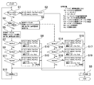
図6は、図5の制御テーブルを用いた各ドットラインの印刷処理の流れを示すフローチャートである。以下、このフローチャートに従って、1ドットラインの印刷処理を説明する。まず、制御部11は、ステップS1において、温度検出器14の出力値Rを検出し、予め設定した基準温度に対応する出力値との比較判定を行う。ここで用いる基準温度は、上述した3種類の基準温度の中の最も低い温度であるインターバル印刷条件よりも更に低い値であり、例えば、17℃(対応する温度検出器14の出力値は71.5KΩ)に設定されている。記録ヘッド5の温度が基準温度以下の場合、すなわち、R≦71.5KΩの場合には(ステップS1:Yes)、制御部11は、ステップS2に進み、駆動モードを設定する。
FIG. 6 is a flowchart showing the flow of printing processing of each dot line using the control table of FIG. Hereinafter, the printing process for one dot line will be described with reference to this flowchart. First, in step S1, the
ステップS2では、制御部11は、ヘッドコイル駆動周波数fを1.44KHzとし、ヘッドコイル通電時間Pwをノーマルモードの場合はPwn+10μs、コピーモードの場合はPwcに設定する。ここで、Pwnは予め設定したノーマルモードの基準通電時間であり、Pwcは予め設定したコピーモードの基準通電時間である。なお、ヘッドコイル駆動インターバルについては、例えば、「特殊ビットイメージ以外」の欄の値の中から、印刷品位に応じた初期インターバル(Tin1)を選択することができる。あるいは、他のインターバル値を別途設定しても良い。続いて、ステップS3に進み、ステップS2で設定した内容の駆動モードで今回の印刷対象の1ドットラインの印刷を実行して、処理を終了する。
In step S2, the
ステップS1において、記録ヘッド5の温度Tが基準温度よりも高い場合には(ステップS1:No)、制御部11は、ステップS4に進み、上述した5箇所のパターン検出領域15における特殊ビットイメージ(第1ドットパターンもしくは第2ドットパターン)の検出処理と、その検出箇所数と基準数Nとの比較判定を行う。特殊ビットイメージを検出したパターン検出領域15(特定領域)の数がN以上であった場合には(ステップS4:Yes)、ステップS5に進む。
In step S1, when the temperature T of the
ステップS5では、制御部11は、図5の制御テーブルを参照して、3種類の基準温度として、今回の印刷データに対して指定されている印刷品位における「特殊ビットイメージ」の欄の温度を選択する。そして、選択した基準温度に対応する出力値Rin、Rhh、Rstを、駆動モードを決定するための判定値として設定する。一方、特殊ビットイメージを検出したパターン検出領域15の数がN未満であった場合には(ステップS4:No)、ステップS6に進み、図5の制御テーブルを参照して、3種類の基準温度として、今回の印刷データに対して指定されている印刷品位における「特殊ビットイメージ以外」の欄の温度を選択する。そして、選択した基準温度に対応する温度検出器14の出力値Rin、Rhh、Rstを、駆動モードを決定するための判定値として設定する。
In step S5, the
ステップS5に進んだ場合には、続いて、ステップS7〜S12において、温度検出器14の出力値RとRin、Rhh、Rstとの比較判定を行い、判定結果に基づいて駆動モードを設定する。ステップS5において、この場合の3種類の基準温度(第2温度)は、それぞれ、65℃、75℃、107℃となっている。まず、ステップS7において、最も低い基準温度であるインターバル印刷条件(65℃)に対応する出力値Rinとの比較判定を行う。ここで、R≦Rin(記録ヘッド5の温度T≦65℃)の場合には(ステップS7:No)、ステップS8に進んで、ヘッドコイル駆動周波数f、ヘッドコイル通電時間の各値を、今回の印刷品位に対応付けられている値に設定する。また、このときのヘッドコイル駆動インターバルを、Tin1に設定する。そして、ステップS3に進み、ステップS8で設定した内容の駆動モードで今回の印刷対象の1ドットラインの印刷を実行して、処理を終了する。
When the process proceeds to step S5, subsequently, in steps S7 to S12, the output value R of the
一方、ステップS7においてR>Rin(記録ヘッド5の温度T>65℃)であった場合には(ステップS7:Yes)、ステップS9に進んで、Uni−D印刷条件(75℃)に対応する出力値Rhhとの比較判定を行う。そして、R≦Rhh(記録ヘッド5の温度T≦75℃)の場合には(ステップS9:No)、ステップS10に進んで、ヘッドコイル駆動周波数f、ヘッドコイル通電時間の各値を、今回の印刷品位に対応付けられている値に設定する。また、このときのヘッドコイル駆動インターバルを、Tin2に設定する。そして、ステップS3に進み、ステップS10で設定した内容の駆動モードで今回の印刷対象の1ドットラインの印刷を実行して、処理を終了する。
On the other hand, if R> Rin (the temperature T of the
次に、ステップS9においてR>Rhh(記録ヘッド5の温度T>75℃)であった場合には(ステップS9:Yes)、ステップS11に進んで、印刷停止条件(107℃)に対応する出力値Rstとの比較判定を行う。そして、R≦Rst(記録ヘッド5の温度T≦107℃)の場合には(ステップS11:No)、ステップS12に進んで、ヘッドコイル駆動周波数f、ヘッドコイル通電時間の各値を、今回の印刷品位に対応付けられている値に設定する。また、このときのヘッドコイル駆動インターバルを、Tin2に設定する。そして、ステップS3に進み、ステップS12で設定した内容の駆動モードで今回の印刷対象の1ドットラインの印刷を実行して、処理を終了する。一方、ステップS11においてR>Rst(107℃)であった場合には(ステップS11:Yes)、ステップS13に進み、予め設定した遅延時間(記録ヘッド5の放熱を行うための時間)の間は印刷を停止する。その後、ステップS1に戻って処理を再開する。 Next, if R> Rhh (temperature T> 75 ° C. of the recording head 5) in step S9 (step S9: Yes), the process proceeds to step S11, and an output corresponding to the print stop condition (107 ° C.). Comparison with the value Rst is performed. If R ≦ Rst (temperature T ≦ 107 ° C. of the recording head 5) (step S11: No), the process proceeds to step S12, and the values of the head coil drive frequency f and the head coil energization time are set to the current value. Set to a value associated with print quality. Further, the head coil driving interval at this time is set to Tin2. Then, the process proceeds to step S3, printing of one dot line to be printed this time is executed in the drive mode having the contents set in step S12, and the process is terminated. On the other hand, if R> Rst (107 ° C.) in step S11 (step S11: Yes), the process proceeds to step S13, and during a preset delay time (time for radiating heat from the recording head 5). Stop printing. Then, it returns to step S1 and restarts processing.
ステップS6に進んだ場合には、ステップS14〜S19において、記録ヘッド5の温度Rと基準温度Rin、Rhh、Rstとの比較判定を行い、判定結果に基づいて駆動モードを設定する。ステップS6において、この場合の基準温度Rin、Rhh、Rst(第1温度)は、それぞれ、102℃、107℃、110℃となっている。ステップS14〜S19は、3種類の基準温度がステップS7〜S12の処理を行う場合よりも高く設定されている点を除いては、ステップS7〜S12と同様に行われる。
In step S6, in steps S14 to S19, the temperature R of the
ここで、ステップS8、S10、S12における駆動モードの設定内容は、ステップS15、S17、S19における各設定内容とそれぞれ一致している。つまり、本実施形態では、図5、図6に示すように、ステップS8、S10、S12の各設定内容に駆動モードを変更するための記録ヘッド5の基準温度が、「特殊ビットイメージ」の場合には「特殊ビットイメージ以外」の場合よりも低くなっており、「特殊ビットイメージ」の場合には、記録ヘッド5の温度が同一であっても、より発熱量の少ない駆動モードに設定される。
Here, the setting contents of the drive mode in steps S8, S10, and S12 are the same as the setting contents in steps S15, S17, and S19, respectively. That is, in this embodiment, as shown in FIGS. 5 and 6, when the reference temperature of the
以上のように、本実施形態では、印刷対象のドットラインにおけるパターン検出領域15と特殊ビットイメージとを照合して、特殊ビットイメージを含むパターン検出領域15の数が基準数N以上の場合には、発熱量が少なく印刷速度が遅い駆動モードに切り替えるための記録ヘッドの温度の基準値を、低い温度(第2温度)に設定している。一方、基準数N未満の場合には、発熱量が少なく印刷速度が遅い駆動モードに切り替えるための記録ヘッドの温度の基準値を、第2温度よりも高い温度(第1温度)に設定している。このため、特殊ビットイメージを含むパターン検出領域15の数が1以下で、記録ヘッドの温度がヘッドコイルの焼損限界温度を越えないことが想定される場合にまで、記録ヘッド5の駆動モードが、発熱量が少なく印刷速度が遅い駆動モードに切り替わることがなくなる。よって、ヘッドコイルの焼損を防止しつつ、必要以上の印刷スループットの低下を抑制できる。
As described above, in the present embodiment, when the
(改変例)
(1)上記実施形態では、特殊ビットイメージとして、同一の記録ワイヤ9により連続して50ドットを形成する第1ドットパターンと、同一の記録ワイヤ9により連続した50ドット分の長さにおいて1ドットおきに25個のドットを形成する第2ドットパターンの2種類を示したが、これ以外のドットパターンを特殊ビットイメージとすることもできる。例えば、特殊ビットイメージを連続ドットとする場合の連続ドットの形成数(すなわち、対応するヘッドコイル10の連続駆動回数)を、各パターン検出領域15の幅、隣接するパターン検出領域15の間隔、1ドットラインの最大ライン長(最大桁)などに対応させて設定することができる。また、各パターン検出領域15の幅に対応するドット数のうち、所定の比率以上ドットが形成されるドットパターンを特殊ビットイメージとすることもできる。あるいは、記録ヘッド5に搭載される複数の記録ワイヤ9のうち、所定数以上が同時に第1ドットパターンもしくは第2ドットパターンを形成するものを、特殊ビットイメージとすることもできる。
(Modification example)
(1) In the above embodiment, as the special bit image, the first dot pattern in which 50 dots are continuously formed by the
(2)上記実施形態では、1ドットラインの範囲にパターン検出領域15を複数設定して、特殊ビットイメージの検出をパターン検出領域15においてのみ行っていたが、パターン検出領域15を設定せず、1ドットラインの最大桁の全範囲で特殊ビットイメージが何箇所検出されるかを判定して、この検出箇所数に基づいて駆動モードを決定することもできる。あるいは、パターン検出領域15の数を増やし、隣接するパターン検出領域15の間の非検出領域の幅をより短くすることもできる。
(2) In the above embodiment, a plurality of
(3)上記実施形態では、検出される特殊ビットイメージの内容(第1ドットパターンと第2ドットパターンのどちらが検出されるか)によって処理を異ならせていないが、検出される特殊ビットイメージの内容に応じて、駆動モードの設定を異ならせても良い。また、特殊ビットイメージを含む複数のパターン検出領域15の間隔や、特殊ビットイメージの近傍の領域におけるドット密度、あるいは、印刷対象のドットラインの印刷前に行った印刷内容(印刷履歴)などを、駆動モードを設定するためのパラメーターとして用いても良い。
(3) In the above embodiment, the processing is not different depending on the content of the detected special bit image (whether the first dot pattern or the second dot pattern is detected), but the content of the detected special bit image Depending on the drive mode, the drive mode may be set differently. In addition, the interval between the plurality of
1…ドットインパクトプリンター、2、3…側板、4…キャリッジガイド軸、5…記録ヘッド、5a…ヘッド面、6…キャリッジ、6a…キャリッジモーター、6b…駆動機構、7…プラテン、8…インクリボン、9…記録ワイヤ、10…ヘッドコイル、11…制御部、11a…記憶部、12…ホスト装置、13…記録紙搬送機構、14…温度検出器、15…パターン検出領域、16…非検出領域
DESCRIPTION OF
Claims (8)
各々の前記記録ワイヤは、キャリッジの走査方向における1ドットラインの印刷を担当しており、
前記ドットラインの最大ライン長の領域内に、所定幅のパターン検出領域を予め複数設
定しておき、
前記ドットラインの印刷において、
印刷実行前に、印刷対象の前記ドットラインにおける前記パターン検出領域が、予め設定した特定のドットパターンを含む特定領域であるか否かを判定し、
前記特定領域であると判定された場合、前記印刷対象の前記ドットラインにおける前記特定領域の数が2以上の基準数以上であるか否かを判定し、
その判定結果に基づいて、前記ドットラインを印刷することを特徴とする記録ヘッドの制御方法。 A method for controlling a recording head in a dot impact printer for printing information on a recording medium by driving the recording wire while scanning a carriage on which a recording head having a plurality of recording wires is mounted,
Each recording wire is in charge of printing one dot line in the scanning direction of the carriage,
A plurality of pattern detection areas having a predetermined width are provided in advance in the area of the maximum line length of the dot lines.
Set
In printing the dot line,
Before printing, it is determined whether the pattern detection area in the dot line to be printed is a specific area including a specific dot pattern set in advance,
Wherein when it is determined that the specific region, the number of the specific area in the dot line of the print target to determine der Luke not more than the reference number,
A printing head control method, wherein the dot lines are printed based on the determination result.
前記判定結果に基づいて、前記ドットラインを印刷するための前記記録ヘッドの駆動モードを決定することを特徴とする請求項1に記載の記録ヘッドの制御方法。 In claim 1,
2. The recording head control method according to claim 1, wherein a driving mode of the recording head for printing the dot line is determined based on the determination result.
前記記録ヘッドの前記駆動モードとして、発熱量が異なる複数の前記駆動モードを予め
設定しておくと共に、各前記駆動モードと前記記録ヘッドの温度とを対応付けておき、
前記各駆動モードに対応付けられている前記記録ヘッドの温度は、第1温度と、前記第
1温度よりも低い第2温度の少なくとも2つの温度を含み、
前記ドットラインの印刷において、
印刷実行前に、前記記録ヘッドの温度を検出し、
印刷対象の前記ドットラインにおける前記特定領域の数が前記基準数以上であった場合
には、前記第2温度を用いて、検出した前記記録ヘッドの温度に対応する前記駆動モード
を選択し、
印刷対象の前記ドットラインにおける前記特定領域の数が前記基準数未満であった場合
には、前記第1温度を用いて、検出した前記記録ヘッドの温度に対応する前記駆動モード
を選択し、
選択した前記駆動モードにより、前記ドットラインの印刷を実行することを特徴とする
記録ヘッドの制御方法。 In claim 2 ,
As the drive mode of the recording head, a plurality of the drive modes with different calorific values are set in advance, and the drive mode and the temperature of the print head are associated with each other,
The temperature of the recording head associated with each drive mode includes at least two temperatures, a first temperature and a second temperature lower than the first temperature,
In printing the dot line,
Detect the temperature of the recording head before printing,
When the number of the specific areas in the dot line to be printed is equal to or more than the reference number, the driving mode corresponding to the detected temperature of the recording head is selected using the second temperature,
When the number of the specific areas in the dot line to be printed is less than the reference number, the drive mode corresponding to the detected temperature of the recording head is selected using the first temperature,
A printing head control method, wherein printing of the dot lines is executed in accordance with the selected driving mode.
印刷実行前に検出した前記記録ヘッドの温度が予め設定した基準温度以下であった場合
には、
前記パターン検出領域が前記特定領域であるか否かの判定結果を用いずに前記記録ヘッ
ドの前記駆動モードを決定することを特徴とする記録ヘッドの制御方法。 In claim 3 ,
When the temperature of the recording head detected before printing is below a preset reference temperature,
A method for controlling a recording head, wherein the driving mode of the recording head is determined without using a determination result as to whether or not the pattern detection region is the specific region.
印刷データの印刷品位と、前記記録ヘッドの前記駆動モードとを対応付けておき、
前記ドットラインの印刷において、
印刷対象の前記ドットラインを含む前記印刷データの印刷品位に対応付けられている前記駆動モードの中から決定した前記駆動モードにより、前記ドットラインの印刷を実行することを特徴とする記録ヘッドの制御方法。 In any one of claims 2 to 4 ,
Associating the print quality of the print data with the drive mode of the recording head,
In printing the dot line,
Control of a recording head, wherein printing of the dot line is executed in accordance with the drive mode determined from the drive modes associated with the print quality of the print data including the dot line to be printed Method.
前記特定のドットパターンは、印刷時に同時に駆動される前記記録ワイヤの数、および、同一の前記記録ワイヤの連続駆動回数に基づいて設定されていることを特徴とする記録
ヘッドの制御方法。 In any one of claims 2 to 5 ,
The method for controlling a recording head, wherein the specific dot pattern is set based on the number of the recording wires that are simultaneously driven during printing and the number of continuous drivings of the same recording wire.
前記キャリッジに搭載され、ドットライン中に印刷ドット列を形成する複数の記録ワイ
ヤを有する記録ヘッドと、
前記記録ヘッドを制御する制御部と、を有し、
前記制御部は、前記ドットラインの最大ライン長の領域内に、所定幅のパターン検出領域を予め複数設定しておき、前記ドットラインの印刷において、印刷実行前に、印刷対象の前記ドットラインにおける前記パターン検出領域が、予め設定した特定のドットパターンを含む特定領域であるか否かを判定し、前記特定領域であると判定された場合、前記印刷対象の前記ドットラインにおける前記特定領域の数が2以上の基準数以上であるか否かを判定し、その判定結果に基づいて、前記ドットラインを印刷することを特徴とするドットインパクトプリンター。 A carriage that is scanned in a direction substantially perpendicular to the feeding direction of the recording medium on which information is printed;
A recording head mounted on the carriage and having a plurality of recording wires forming a print dot row in a dot line;
A control unit for controlling the recording head,
The control unit sets in advance a plurality of pattern detection areas having a predetermined width within the area of the maximum line length of the dot lines, and in the printing of the dot lines, the dot lines to be printed are printed before printing. It is determined whether or not the pattern detection area is a specific area including a specific dot pattern that is set in advance. If it is determined that the specific area is the specific area, the pattern detection area of the specific area in the dot line to be printed number determines whether der Luke 2 or more than the reference number, based on the determination result, a dot impact printer, which comprises printing the dot line.
前記制御部は、前記判定結果に基づいて、前記ドットラインを印刷するための前記記録ヘッドの駆動モードを決定することを特徴とするドットインパクトプリンター。 In claim 7 ,
The dot impact printer, wherein the control unit determines a drive mode of the recording head for printing the dot line based on the determination result.
Priority Applications (4)
| Application Number | Priority Date | Filing Date | Title |
|---|---|---|---|
| JP2009294060A JP5402618B2 (en) | 2009-12-25 | 2009-12-25 | Recording head control method and dot impact printer |
| US12/963,533 US8979237B2 (en) | 2009-12-25 | 2010-12-08 | Recording head control method and dot impact printer |
| CN201010621526.3A CN102152646B (en) | 2009-12-25 | 2010-12-24 | Recording head control method and dot impact printer |
| CN201310446832.1A CN103552383B (en) | 2009-12-25 | 2010-12-24 | The control method of record head |
Applications Claiming Priority (1)
| Application Number | Priority Date | Filing Date | Title |
|---|---|---|---|
| JP2009294060A JP5402618B2 (en) | 2009-12-25 | 2009-12-25 | Recording head control method and dot impact printer |
Publications (3)
| Publication Number | Publication Date |
|---|---|
| JP2011131519A JP2011131519A (en) | 2011-07-07 |
| JP2011131519A5 JP2011131519A5 (en) | 2013-01-17 |
| JP5402618B2 true JP5402618B2 (en) | 2014-01-29 |
Family
ID=44344767
Family Applications (1)
| Application Number | Title | Priority Date | Filing Date |
|---|---|---|---|
| JP2009294060A Expired - Fee Related JP5402618B2 (en) | 2009-12-25 | 2009-12-25 | Recording head control method and dot impact printer |
Country Status (1)
| Country | Link |
|---|---|
| JP (1) | JP5402618B2 (en) |
Families Citing this family (1)
| Publication number | Priority date | Publication date | Assignee | Title |
|---|---|---|---|---|
| JP2014069481A (en) * | 2012-09-28 | 2014-04-21 | Oki Data Corp | Printer and method for driving print-head |
Family Cites Families (2)
| Publication number | Priority date | Publication date | Assignee | Title |
|---|---|---|---|---|
| JP3206788B2 (en) * | 1993-12-24 | 2001-09-10 | セイコーエプソン株式会社 | Impact dot printer |
| JP2004098617A (en) * | 2002-09-12 | 2004-04-02 | Seiko Epson Corp | Dot impact printer, control method therefor, program for performing control method and recording medium on which program is recorded |
-
2009
- 2009-12-25 JP JP2009294060A patent/JP5402618B2/en not_active Expired - Fee Related
Also Published As
| Publication number | Publication date |
|---|---|
| JP2011131519A (en) | 2011-07-07 |
Similar Documents
| Publication | Publication Date | Title |
|---|---|---|
| US5477245A (en) | Temperatures control system for ink-jet recording apparatus | |
| JP5540653B2 (en) | Thermal printer and its energization control method | |
| JP5477313B2 (en) | Inkjet recording device | |
| EP2741484A2 (en) | Image forming apparatus and image forming method | |
| US8979237B2 (en) | Recording head control method and dot impact printer | |
| JP5402618B2 (en) | Recording head control method and dot impact printer | |
| JP3013495B2 (en) | Printer | |
| JP2006341570A (en) | Ink jet recording device and method of ink jet recording | |
| JP2011126127A (en) | Inkjet recording device and method for forming test pattern | |
| JP4921055B2 (en) | Conveying device and recording apparatus provided with the device | |
| JPS639556A (en) | Printing-controlling system | |
| JP6187026B2 (en) | Dot impact printer | |
| JP2011255632A (en) | Recording head control method and dot impact printer | |
| JP5636749B2 (en) | Recording head control method and dot impact printer | |
| JP2018039233A (en) | Serial type recording device | |
| JP2006082425A (en) | Color thermal printer and printer | |
| JP2005219454A (en) | Printing method and printer | |
| JP2009181116A (en) | Recording device and medium transportation method in recording device | |
| JP5028432B2 (en) | Image recording apparatus and control method of image recording apparatus | |
| JP3934375B2 (en) | Line thermal printer recording method and line thermal printer used therefor | |
| JP3015385B2 (en) | Ink jet recording device | |
| JP2005186510A (en) | Line type thermal printer and its divide driving method | |
| JP2009034824A (en) | Recording device and its control method | |
| JP3865040B2 (en) | Recording paper transport amount control device and recording paper transport amount control method | |
| JP2011131519A5 (en) |
Legal Events
| Date | Code | Title | Description |
|---|---|---|---|
| A521 | Request for written amendment filed |
Free format text: JAPANESE INTERMEDIATE CODE: A523 Effective date: 20121127 |
|
| A621 | Written request for application examination |
Free format text: JAPANESE INTERMEDIATE CODE: A621 Effective date: 20121127 |
|
| A131 | Notification of reasons for refusal |
Free format text: JAPANESE INTERMEDIATE CODE: A131 Effective date: 20130709 |
|
| A521 | Request for written amendment filed |
Free format text: JAPANESE INTERMEDIATE CODE: A523 Effective date: 20130905 |
|
| TRDD | Decision of grant or rejection written | ||
| A01 | Written decision to grant a patent or to grant a registration (utility model) |
Free format text: JAPANESE INTERMEDIATE CODE: A01 Effective date: 20131001 |
|
| A61 | First payment of annual fees (during grant procedure) |
Free format text: JAPANESE INTERMEDIATE CODE: A61 Effective date: 20131014 |
|
| R150 | Certificate of patent or registration of utility model |
Ref document number: 5402618 Country of ref document: JP Free format text: JAPANESE INTERMEDIATE CODE: R150 |
|
| S531 | Written request for registration of change of domicile |
Free format text: JAPANESE INTERMEDIATE CODE: R313531 |
|
| R350 | Written notification of registration of transfer |
Free format text: JAPANESE INTERMEDIATE CODE: R350 |
|
| LAPS | Cancellation because of no payment of annual fees |