JP5401405B2 - Horizontally Striped Solid Oxide Fuel Cell Stack, Horizontally Striped Solid Oxide Fuel Cell Bundle, and Fuel Cell - Google Patents
Horizontally Striped Solid Oxide Fuel Cell Stack, Horizontally Striped Solid Oxide Fuel Cell Bundle, and Fuel Cell Download PDFInfo
- Publication number
- JP5401405B2 JP5401405B2 JP2010143026A JP2010143026A JP5401405B2 JP 5401405 B2 JP5401405 B2 JP 5401405B2 JP 2010143026 A JP2010143026 A JP 2010143026A JP 2010143026 A JP2010143026 A JP 2010143026A JP 5401405 B2 JP5401405 B2 JP 5401405B2
- Authority
- JP
- Japan
- Prior art keywords
- porous support
- fuel cell
- electrode layer
- fuel
- solid oxide
- Prior art date
- Legal status (The legal status is an assumption and is not a legal conclusion. Google has not performed a legal analysis and makes no representation as to the accuracy of the status listed.)
- Active
Links
Images


Classifications
-
- Y—GENERAL TAGGING OF NEW TECHNOLOGICAL DEVELOPMENTS; GENERAL TAGGING OF CROSS-SECTIONAL TECHNOLOGIES SPANNING OVER SEVERAL SECTIONS OF THE IPC; TECHNICAL SUBJECTS COVERED BY FORMER USPC CROSS-REFERENCE ART COLLECTIONS [XRACs] AND DIGESTS
- Y02—TECHNOLOGIES OR APPLICATIONS FOR MITIGATION OR ADAPTATION AGAINST CLIMATE CHANGE
- Y02E—REDUCTION OF GREENHOUSE GAS [GHG] EMISSIONS, RELATED TO ENERGY GENERATION, TRANSMISSION OR DISTRIBUTION
- Y02E60/00—Enabling technologies; Technologies with a potential or indirect contribution to GHG emissions mitigation
- Y02E60/30—Hydrogen technology
- Y02E60/50—Fuel cells
Description
本発明は、横縞型固体酸化物形燃料電池セルスタック(以下、単にセルスタックという場合がある。)、横縞型固体酸化物形燃料電池バンドル(以下、単にバンドルという場合がある。)および燃料電池に関する。 The present invention relates to a horizontally-striped solid oxide fuel cell stack (hereinafter simply referred to as a cell stack), a horizontally-striped solid oxide fuel cell bundle (hereinafter sometimes simply referred to as a bundle), and a fuel cell. About.
近年、エネルギー変換段数を少なくし、化学エネルギーを直接電気エネルギーに変換する高い発電効率を有する発電方法として、燃料電池が注目されている。とりわけ、固体酸化物形燃料電池は、発電温度が600℃〜1000℃と高く、燃料電池内の内部抵抗が小さいため、燃料電池の中で最も発電効率が高く、さらに残燃料を利用してガスタービンによるさらなる発電、あるいはコージェネレーション用の熱源として用いることができ、化学エネルギーを高い変換効率で電気エネルギーに変換できる特性を有する。特に横縞型固体酸化物形燃料電池は、少ないセルスタックの本数で高い電圧を得られるが、室温と高い作動温度との間のヒートサイクルによって生じる熱応力に強いセルスタックとする必要がある。 In recent years, fuel cells have attracted attention as a power generation method having high power generation efficiency in which the number of energy conversion stages is reduced and chemical energy is directly converted into electric energy. In particular, a solid oxide fuel cell has a high power generation temperature of 600 ° C. to 1000 ° C. and a low internal resistance in the fuel cell, so that it has the highest power generation efficiency among the fuel cells, and further uses residual fuel for gas. It can be used as a heat source for further power generation by a turbine or cogeneration, and has the property of converting chemical energy into electrical energy with high conversion efficiency. In particular, the horizontal stripe solid oxide fuel cell can obtain a high voltage with a small number of cell stacks, but needs to be a cell stack resistant to thermal stress caused by a heat cycle between room temperature and a high operating temperature.
従来のセルスタックは、長手方向に沿って燃料ガスを流すためのガス流路を内部に備え、一端側にガス流路の燃料ガス導入口を有し、他端側にガス流路の燃料ガス排出口を有してなる電気絶縁性の多孔質支持体上に、燃料極層、固体電解質層および空気極層が順次積層された多層構造の燃料電池セルを複数個有する(特許文献1および2参照)。
A conventional cell stack has a gas flow path for flowing fuel gas along the longitudinal direction, has a gas flow path for fuel gas at one end, and a fuel gas for the gas flow path at the other end. A plurality of fuel cells having a multilayer structure in which a fuel electrode layer, a solid electrolyte layer, and an air electrode layer are sequentially laminated on an electrically insulating porous support having a discharge port are provided (
このようなセルスタックでは、上記のようなヒートサイクルの繰り返しによって、多孔質支持体の燃料ガス排出口側の端部を被覆している固体電解質層が破壊する場合があるという問題がある。例えば、発電までの起動時間を短くするために急激に900℃付近の温度まで加熱し、室温まで降温する操作(ヒートサイクル)を繰り返したり、あるいは、燃料ガス排出口から排出される燃料ガスを燃焼させ、ついで燃料ガスの供給を止めて室温まで降温させる操作(ヒートサイクル)を繰り返したりすると、多孔質支持体の燃料ガス排出口側の端部を被覆している固体電解質層が早期に破壊する場合がある。 In such a cell stack, there is a problem that the solid electrolyte layer covering the end on the fuel gas discharge port side of the porous support may be broken by the repetition of the heat cycle as described above. For example, in order to shorten the start-up time until power generation, an operation (heat cycle) in which the temperature is suddenly heated to around 900 ° C. and lowered to room temperature is repeated, or the fuel gas discharged from the fuel gas discharge port is burned Then, when the operation (heat cycle) of stopping the supply of fuel gas and lowering the temperature to room temperature is repeated, the solid electrolyte layer covering the end of the porous support on the fuel gas discharge port side is destroyed early. There is a case.
そこで、本発明は、ヒートサイクルの繰り返しによっても、多孔質支持体の燃料ガス排出口側の端部を被覆している固体電解質層が破壊され難いセルスタック、バンドル及び燃料電池を提供することを目的とする。 Therefore, the present invention provides a cell stack, a bundle, and a fuel cell in which the solid electrolyte layer covering the end portion of the porous support on the fuel gas discharge port side is not easily broken even by repeated heat cycles. Objective.
本発明者らは、上記課題を解決すべく鋭意研究を重ねる過程で、上記のように、ヒートサイクルにより多孔質支持体の燃料ガス排出口側の端部を被覆している固体電解質層が破壊されるのは、燃焼中に多孔質支持体の端部側に大きな温度変化を伴うことで端部側に熱応力が生じることや、多孔質支持体が酸化還元に伴って膨張収縮することによって、多孔質支持体の燃料ガス排出口側の端部を被覆している固体電解質層が多孔質支持体により負荷される応力に対し強度的に耐えられなくなるためではないかと推測した。従って、多孔質支持体の燃料ガス排出口側の端部を被覆している固体電解質層の破壊を抑制するためには、当該多孔質支持体の端部領域の低膨張化が必要であると考え、鋭意研究を重ねた。その結果、Niおよび/またはNiO(以下、Ni等という場合がある。)を含有してなる多孔質支持体の燃料ガス排出口側の端部領域のNiのNiO換算での含有量(以下、Ni含有量という場合がある。)を、多孔質支持体の燃料ガス排出口側の端部領域以外である燃料電池セルが設けられた領域のNi含有量よりも少なくすることにより、燃料ガス排出口側の端部を被覆している固体電解質層が破壊され難いセルスタックを提供することができるという知見を得て、本発明を完成するに至った。 As described above, the inventors of the present invention, in the process of earnestly researching to solve the above-described problems, destroyed the solid electrolyte layer covering the end portion of the porous support on the fuel gas outlet side by heat cycle as described above. This is because thermal stress is generated on the end side due to a large temperature change on the end side of the porous support during combustion, and the porous support expands and contracts due to oxidation and reduction. It was speculated that the solid electrolyte layer covering the end of the porous support on the fuel gas discharge port side could not withstand the stress applied by the porous support in terms of strength. Therefore, in order to suppress the destruction of the solid electrolyte layer covering the end of the porous support on the fuel gas discharge port side, it is necessary to reduce the expansion of the end region of the porous support. I thought and worked hard. As a result, the Ni content in terms of NiO in the end region on the fuel gas outlet side of the porous support containing Ni and / or NiO (hereinafter sometimes referred to as Ni) (hereinafter referred to as NiO). By reducing the Ni content in the region where the fuel cells other than the end region on the fuel gas discharge port side of the porous support are provided, the fuel gas emission is reduced. The present invention has been completed by obtaining the knowledge that the solid electrolyte layer covering the end portion on the outlet side can be provided with a cell stack that is not easily destroyed.
すなわち、本発明は以下の構成からなる。
(1)長手方向に沿って燃料ガスを流すためのガス流路を内部に備え、一端側に前記ガス流路の燃料ガス導入口を有し、他端側に前記ガス流路の燃料ガス排出口を有してなり、Niおよび/またはNiOを含有してなる電気絶縁性の多孔質支持体上に、内側電極層、固体電解質層および外側電極層が順次積層された多層構造を有する燃料電池セルが前記多孔質支持体の長手方向に沿って複数個配置されて発電領域が形成され、前記多孔質支持体の他端側の端部が固体電解質層で被覆されて非発電領域が形成されてなる横縞型固体酸化物形燃料電池セルスタックであって、前記非発電領域の少なくとも先端部における前記多孔質支持体のNiのNiO換算での含有量が、前記発電領域における前記多孔質支持体のNiのNiO換算での含有量よりも少ないことを特徴とする横縞型固体酸化物形燃料電池セルスタック。
(2)前記非発電領域の少なくとも先端部における前記多孔質支持体のNiのNiO換算での含有量が、2.0mol%以上6.0mol%未満であることを特徴とする前記(1)に記載の横縞型固体酸化物形燃料電池セルスタック。
(3)前記非発電領域の少なくとも先端部における前記多孔質支持体のNiのNiO換算での含有量が、3.0mol%〜5.0mol%であることを特徴とする前記(1)または(2)に記載の横縞型固体酸化物形燃料電池セルスタック。
(4)前記発電領域における前記多孔質支持体のNiのNiO換算での含有量が、6.0mol%〜22.0mol%であることを特徴とする前記(1)〜(3)のいずれかに記載の横縞型固体酸化物形燃料電池セルスタック。
(5)複数本の前記(1)〜(4)のいずれかに記載の横縞型固体酸化物形燃料電池セルスタックの一端側を、前記ガス流路に前記反応ガスを供給するためのガスマニホールドに固定してなる横縞型固体酸化物形燃料電池バンドル。
(6)前記(5)に記載の横縞型固体酸化物形燃料電池バンドルを収納容器内に複数収容してなることを特徴とする燃料電池。
That is, the present invention has the following configuration.
(1) A gas flow path for flowing fuel gas along the longitudinal direction is provided inside, the fuel gas introduction port of the gas flow path is provided on one end side, and the fuel gas discharge of the gas flow path is provided on the other end side. A fuel cell having a multilayer structure in which an inner electrode layer, a solid electrolyte layer, and an outer electrode layer are sequentially laminated on an electrically insulating porous support having an outlet and containing Ni and / or NiO A plurality of cells are arranged along the longitudinal direction of the porous support to form a power generation region, and the other end of the porous support is covered with a solid electrolyte layer to form a non-power generation region. A horizontally-striped solid oxide fuel cell stack, wherein the content of Ni in NiO conversion of the porous support at least at the tip of the non-power generation region is the porous support in the power generation region. Ni content in terms of NiO Segmented-in-series solid oxide fuel cell stack, characterized in that also small.
(2) The above (1) is characterized in that the content of Ni in terms of NiO in the porous support at least at the tip of the non-power generation region is 2.0 mol% or more and less than 6.0 mol%. The horizontal stripe type solid oxide fuel cell stack described.
(3) The content of Ni in terms of NiO in the porous support at least at the tip of the non-power generation region is 3.0 mol% to 5.0 mol%, (1) or (1) The horizontally-striped solid oxide fuel cell stack according to 2).
(4) Any of (1) to (3) above, wherein the Ni content of the porous support in the power generation region in terms of NiO is 6.0 mol% to 22.0 mol%. 2. A horizontally-striped solid oxide fuel cell stack according to 1.
(5) A gas manifold for supplying the reaction gas to the gas flow path at one end of the plurality of horizontal stripe solid oxide fuel cell stacks according to any one of (1) to (4) A horizontally-striped solid oxide fuel cell bundle fixed to
(6) A fuel cell comprising a plurality of horizontally-striped solid oxide fuel cell bundles according to (5), which are accommodated in a storage container.
本発明によれば、ヒートサイクルを繰り返しても、多孔質支持体の燃料ガス排出口側の端部を被覆している固体電解質層が破壊されにくく、耐久性、信頼性の高いセルスタックを提供することができる。さらに、本発明のセルスタックを用いた長期信頼性の高いバンドルおよび燃料電池を提供することができる。 According to the present invention, even when the heat cycle is repeated, the solid electrolyte layer covering the end portion of the porous support on the fuel gas discharge port side is not easily broken, and a highly durable and reliable cell stack is provided. can do. Furthermore, a bundle and a fuel cell having high long-term reliability using the cell stack of the present invention can be provided.
以下、本発明のセルスタックおよびそれを用いた燃料電池の一実施形態について、図面を参照して詳細に説明する。 Hereinafter, an embodiment of a cell stack of the present invention and a fuel cell using the same will be described in detail with reference to the drawings.
<セルスタック>
図1は、本実施形態にかかるセルスタック1aの一部を破断して示す斜視図である。図2は、本実施形態にかかるセルスタック1aの燃料ガス排出口側の端部を拡大して示す縦断面図である。
<Cell stack>
FIG. 1 is a perspective view showing a part of a cell stack 1a according to the present embodiment in a cutaway manner. FIG. 2 is an enlarged longitudinal sectional view showing an end portion of the cell stack 1a on the fuel gas discharge port side according to the present embodiment.
図1および図2に示すように、このセルスタック1aは、中空平板状の電気絶縁性の多孔質支持体11の表裏面に、複数の燃料電池セル13を多孔質支持体11の長手方向(以下、単に長手方向という場合がある。)に沿って複数個配置し、それらを、セル間接続部材17を介して電気的に直列に接続した発電領域26と、燃料ガス排出口側の燃料セル13が設けられていない非発電領域25とから成る、「横縞型固体酸化物形燃料電池」といわれるものである。なお、図2に示すセルスタック1aにおいては、後述する非発電領域25のガス流路12の先端部の一部に固体電解質層13bが被覆されている。
As shown in FIGS. 1 and 2, the cell stack 1 a has a plurality of
図1に示すそれぞれの燃料電池セル13は、第1の内側電極層である集電燃料極層13dおよび第2の内側電極層である活性燃料極層13a、固体電解質層13b並びに外側電極層である空気極層13cを順次積層した層構造となっており、集電燃料極層13d上にインターコネクタ17aが配置されている。なお、以下の説明において、内側電極層を燃料極層(集電燃料極層13dおよび活性燃料極層13a)とし、外側電極層を空気極層13cとした構成からなるタイプのセルスタックを用いて説明する。
Each
多孔質支持体11の表裏面における互いに隣接する燃料電池セル13同士は、セル間接続部材17により電気的に直列に接続されている(図2参照)。すなわち、一方の燃料電池セル13の集電燃料極層13dの上にインターコネクタ17aが形成され、このインターコネクタ17aは、長手方向両端部を含めその周囲が固体電解質層13bによりガスシール状態で被覆され、固体電解質層13bから帯状に露出している。このインターコネクタ17aの露出した部分がセル接続材17bにより被覆され、このセル接続材17bが、他方の燃料電池セル13の空気極層13c上に形成され、これにより、燃料電池セル13同士が電気的に直列に電気的に接続された構造となっている。
The
多孔質支持体11は多孔質であり、さらにその内部には、内径の小さな複数のガス流路12が、長手方向に延びるようにして貫通して設けられている。前記ガス流路12の数は、発電性能および構造強度の点から、例えば3〜20個が好ましく、6〜17個であるのがより好ましい。このように、多孔質支持体11の内部にガス流路12を複数形成することにより、多孔質支持体11の内部に大きなガス流路を1本形成する場合に比べて、多孔質支持体11を扁平板状とすることができ、セルスタック1aの体積当たりの燃料電池セル13の面積を増加し発電量を大きくすることができる。よって、例えば、必要とする発電量を得るためにバンドル20を構成する際に、セルスタック1aの本数を減らすことができる。
The
このガス流路12内に水素ガスを含む燃料ガスを流し、かつ空気極層13cを空気等の酸素を含む酸素含有ガスに曝すことにより、活性燃料極層13aおよび空気極層13c間で下記式(i)および(ii)に示す電極反応が生じ、両極間に電位差が発生し、発電するようになっている。
By flowing a fuel gas containing hydrogen gas into the
また、セルスタック1aの多孔質支持体11の燃料ガス排出口側の端面18の外縁の角部は面取りされていてもよい(図示せず。)。面取りされることで、燃料ガス排出口側の端部に熱応力が集中するのを緩和して、セルスタック1aの製造時や該セルスタック1aで構成されるバンドル20aを収納してなる燃料電池の運転時に、セルスタックの破損を抑制することができる。
Moreover, the corner | angular part of the outer edge of the
多孔質支持体11の燃料ガス排出口側の端面18の外周の角部の面取りとしては、例えば、C面形状、R面形状の他、C面形状とR面形状の組み合わせ等、一般的に知られている面取り形状を、適宜設定することができる。
As the chamfering of the corner of the outer periphery of the
セルスタック1aの多孔質支持体11の燃料ガス排出口側の端面18の外縁の角部に施す面取りの大きさとしては、適宜設定することができるが、例えば、多孔質支持体11の厚みが2〜5mmの場合においては、多孔質支持体11の燃料ガス排出口側の端部の強度等を考慮して、多孔質支持体11のガス流路12の燃料ガス排出口側の端部から(ガス流路12の孔の端から)面取りの後の角部までの長さが少なくとも350μm以上となる大きさとすることが好ましい。
The size of the chamfer applied to the corner of the outer edge of the
以下、セルスタック1aを構成する各部材の材質等を詳しく説明する。
(多孔質支持体11)
本発明に係る多孔質支持体11は、少なくともNi等(NiOは、発電時には、通常、水素ガスにより還元されてNiとして存在し、以下Ni等という場合がある。)を含有し、他にMg酸化物(以下、MgOという場合がある。)および希土類元素酸化物を含有するのが好ましく、さらにFe2O3を含有していてもよい。なお、希土類元素酸化物を構成する希土類元素としては、Y、La、Yb、Tm、Er、Ho、Dy、Gd、Sm、Prなどを例示することができ、希土類元素酸化物としては、例えばY2O3やYb2O3等が挙げられ、特にY2O3が好ましい。
また、多孔質支持体11は、燃料電池セル13間の電気的ショートを防ぐために電気絶縁性であることが必要であり、通常、105Ω・cm以上の抵抗率を有することが望ましい。
Hereinafter, materials and the like of each member constituting the cell stack 1a will be described in detail.
(Porous support 11)
The
In addition, the
本発明に係る多孔質支持体11において、非発電領域25の少なくとも先端部における多孔質支持体11bのNi含有量は、発電領域26における多孔質支持体11aのNi含有量よりも少ない。
多孔質支持体11bは、多孔質支持体11の燃料ガス排出口側の端面18から発電領域26までの領域の多孔質支持体11の一部分であれば、特に限定されず、燃料ガス排出口側の端面18からガス排出口27近傍のガス流路12が固体電解質層13bで被覆された部分(図2の多孔質支持体11bに該当する。)までの領域の多孔質支持体11の一部分であってもよいし、非発電領域25全域の多孔質支持体11の一部であってもよい。なお、多孔質支持体11bを、固体電解質層13bで被覆された領域全体とすることで、ガス流路12内面に被覆された固体電解質層13bが破壊されにくく、耐久性、信頼性の高いセルスタック1aを提供することができる。
なお、多孔質支持体11bが非発電領域25全域の多孔質支持体11の一部でない場合の非発電領域25における多孔質支持体11b以外の多孔質支持体11の一部である多孔質支持体11c(図2参照)は、製造容易性の観点から、多孔質支持体11aの組成と同等であるのが好ましく、以下、多孔質支持体11aおよび多孔質支持体11cは、単に多孔質支持体11aという。
In the
The
Note that the
以下、Ni等、MgOおよび希土類元素酸化物からなる多孔質支持体11(多孔質支持体11aおよび多孔質支持体11b)について説明するが、本発明はこれに限定されない。
Hereinafter, the porous support 11 (porous support 11a and
<多孔質支持体11a>
多孔質支持体11aのNi含有量は、6.0〜22.0mol%、好ましくは10.0〜18.0mol%、MgOの含有量は、70.0〜75.0mol%、好ましくは70.0〜72.0mol%、希土類元素酸化物の含有量は10.0〜15.0mol%、好ましくは10.0〜13.0mol%の範囲である。
この多孔質支持体11aの熱膨張係数は、通常、10.5〜12.5×10⁻⁶(1/K)程度である。
<Porous support 11a>
The Ni content of the porous support 11a is 6.0 to 22.0 mol%, preferably 10.0 to 18.0 mol%, and the MgO content is 70.0 to 75.0 mol%, preferably 70. 0 to 72.0 mol%, and the rare earth element oxide content is in the range of 10.0 to 15.0 mol%, preferably 10.0 to 13.0 mol%.
The thermal expansion coefficient of the porous support 11a is usually about 10.5 to 12.5 × 10 −6 (1 / K).
Ni含有量が前記範囲を超えると、電気抵抗値が低下し易い。また、Ni含有量が前記範囲よりも少ないと、希土類元素酸化物(例えばY2O3)を単独で用いた場合と変わらなくなってしまい、燃料電池セル13との熱膨張係数の調整が困難となる傾向があり、又燃料ガスの改質効果が不十分となる傾向にある。
MgOの含有量が前記範囲外の場合には、燃料電池セル13との熱膨張係数の調整が困難となる傾向がある。
希土類元素酸化物の含有量が前記範囲外の場合には、燃料電池セル13との熱膨張係数の調整が困難となる傾向がある。
If the Ni content exceeds the above range, the electrical resistance value tends to decrease. In addition, if the Ni content is less than the above range, it is not different from the case where a rare earth element oxide (for example, Y 2 O 3 ) is used alone, and it is difficult to adjust the thermal expansion coefficient with the
When the content of MgO is outside the above range, it tends to be difficult to adjust the thermal expansion coefficient with the
When the content of the rare earth element oxide is outside the above range, it tends to be difficult to adjust the thermal expansion coefficient with the
<多孔質支持体11b>
多孔質支持体11bのNi含有量は、2.0mol%以上6.0mol%未満、好ましくは3.0〜5.0mol%であり、MgOの含有量は75.0〜85.0mol%、好ましくは78.0〜82.0mol%であり、希土類元素酸化物の含有量は10.0〜20.0mol%、好ましくは13.0〜18.0mol%の範囲である。
この多孔質支持体11bの熱膨張係数は、通常、10.5〜12.5×10⁻⁶(1/K)程度である。
<
The Ni content of the
The thermal expansion coefficient of the
多孔質支持体11bのNi含有量が前記範囲を超えると、例えば、急激に900℃付近の温度まで加熱し、室温まで降温するヒートサイクルを繰り返したり、あるいは、燃料ガス排出口から排出される燃料ガスを燃焼させ、ついで燃料ガスの供給を止めて室温まで降温させるヒートサイクルを繰り返したりすると、多孔質支持体11の燃料ガス排出口である他端側の端部や燃料ガス排出口近傍のガス流路内面を被覆している固体電解質層13bが早期に破壊する場合がある。また、Ni含有量が前記範囲よりも少ないと、希土類元素酸化物(例えばY2O3)を単独で用いた場合と変わらなくなってしまい、燃料電池セル13との熱膨張係数の調整が困難となる傾向があり、また燃料ガスの改質効果が不十分となる傾向にある。
MgOの含有量が前記範囲外の場合には、燃料電池セル13との熱膨張係数の調整が困難となる傾向がある。
希土類元素酸化物の含有量が前記範囲外の場合には、燃料電池セル13との熱膨張係数の調整が困難となる傾向がある。
When the Ni content of the
When the content of MgO is outside the above range, it tends to be difficult to adjust the thermal expansion coefficient with the
When the content of the rare earth element oxide is outside the above range, it tends to be difficult to adjust the thermal expansion coefficient with the
以上のように多孔質支持体11は、多孔質支持体11aおよび多孔質支持体11bからなることで、非発電領域の燃料ガス排出口側では、酸化還元による膨張収縮が抑制され、発電領域では燃料ガスの改質反応をすることができる優れた性能を兼ね備えた多孔質支持体11とすることができ、優れた発電性能を維持しつつ耐久性、信頼性を向上させることが可能なセルスタック1aとすることができる。
As described above, the
なお、特に、多孔質支持体11aは、ガス流路12内の燃料ガスを燃料極層まで導入可能でなければならず、このため、多孔質であることが必要である。一般に、その開気孔率は25%以上、特に30〜40%の範囲にあるのがよい。なお、多孔質支持体11bも同様の開気孔率とすることができる。
In particular, the porous support 11a must be able to introduce the fuel gas in the
なお、多孔質支持体11におけるNi量は、以下のようにして検量することができる。例えば、予め所定量のNiを含有して作製した多孔質支持体を複数作製し、それらを、例えばEPMA(X線マイクロアナライザ)にて分析して検量線を作成する。Ni量を求める対象となる多孔質支持体をEPMAにて分析し、先に求めた検量線に基づいて、Ni量を求めることができる。
The amount of Ni in the
(燃料極層)
燃料極層は、前記式(ii)の電極反応を生じさせるものであり、本実施形態においては、固体電解質層13b側の活性燃料極層13aと、多孔質支持体11側の集電燃料極層13dとの二層構造に形成されている。なお、燃料極層は、必ずしも活性燃料極層13aと集電燃料極層13dとの2層より形成する必要はなく、1層のみから形成することもできる。
(Fuel electrode layer)
The fuel electrode layer causes the electrode reaction of the formula (ii). In this embodiment, the active
<活性燃料極層13a>
固体電解質層13b側の活性燃料極層13aは、それ自体公知の多孔質の導電性セラミックスから形成される。例えば、希土類元素が固溶しているZrO2(安定化ジルコニア)と、Ni等とからなる。この希土類元素が固溶した安定化ジルコニアとしては、後述する固体電解質層13bに使用されているものと同様のものを用いるのがよい。
<Active
The active
活性燃料極層13aの安定化ジルコニア含有量は、35〜65体積%、好ましくは45〜55体積%であり、Ni含有量は、良好な発電性能を発揮させるため、NiO換算で65〜35体積%、好ましくは45〜55体積%の範囲にあるのがよい。
活性燃料極層13aの熱膨張係数は、通常、12.3×10⁻⁶(1/K)程度である。
安定化ジルコニア含有量が前記範囲を超えると、電気抵抗が大きくなる。安定化ジルコニア含有量が前記範囲よりも少ないと、熱膨張係数が大きくなり、活性燃料極層13aの剥離等の不具合が発生する。
Ni含有量が前記範囲を超えると、熱膨張係数が大きくなり活性燃料極層13aの剥離等の不具合が発生する。Ni含有量が前記範囲よりも少ないと、電気抵抗が大きくなり燃料極としての機能を失う。
The stabilized zirconia content of the active
The thermal expansion coefficient of the active
When the stabilized zirconia content exceeds the above range, the electrical resistance increases. When the stabilized zirconia content is less than the above range, the thermal expansion coefficient increases, and problems such as separation of the active
If the Ni content exceeds the above range, the coefficient of thermal expansion increases and problems such as separation of the active
また、固体電解質層13bとの熱膨張差に起因して発生する熱応力を吸収し、活性燃料極層13aの割れや剥離などを防止するという点から、活性燃料極層13aの厚みは、5〜30μmの範囲にあることが望ましい。
さらに活性燃料極層13aの開気孔率は、15%以上、好ましくは20〜40%の範囲にあるのがよい。
In addition, the thickness of the active
Further, the open porosity of the active
<集電燃料極層13d>
燃料極層のうち、多孔質支持体11側の集電燃料極層13dは、多孔質支持体11と同様、Ni等と、希土類元素酸化物との混合体より形成することが好ましい。
<Current collecting
Among the fuel electrode layers, the current collecting
集電燃料極層13dのNi含有量は、NiO換算で30〜60体積%、好ましくは45〜55体積%であり、希土類元素酸化物の含有量は、40〜70体積%、好ましくは45〜55体積%の範囲である。
この集電燃料極層13dの熱膨張係数は、通常、11.5×10⁻⁶(1/K)程度である。
Ni含有量および希土類元素酸化物の含有量を上記範囲で調整することにより、多孔質支持体11aと集電燃料極層13dとの熱膨張差を2×10⁻⁶(1/K)以下とすることができる。集電燃料極層13dは、電流の流れを損なわないように、導電性であることが必要であり、通常、400S/cm以上の導電率を有していることが望ましい。良好な電気伝導度を有するという点から、Ni含有量は30体積%以上が望ましい。
The Ni content of the current collecting
The thermal expansion coefficient of the current collecting
By adjusting the Ni content and the rare earth element oxide content within the above ranges, the thermal expansion difference between the porous support 11a and the current collecting
また、この集電燃料極層13dの厚みは、電気伝導度を向上するという点から、80〜200μmであることが望ましい。
Further, the thickness of the current collecting
以上のように、燃料極層を固体電解質層13b側の活性燃料極層13aと、多孔質支持体11側の集電燃料極層13dとの二層とした構造であれば、多孔質支持体11側の集電燃料極層13dのNi含有量あるいはNiO換算でのNiO量を30〜60体積%の範囲内で調整することにより、熱膨張係数を、後述する固体電解質層13bの熱膨張係数に近づけることができ、例えば両者の熱膨張差を2×10⁻⁶(1/K)未満とすることができる。したがって、セルスタック1aの作製時、加熱時、冷却時において両者の熱膨張差に起因して発生する熱応力を小さくすることができるため、燃料極層の割れや剥離などを抑制することができる。このため、燃料ガス(水素ガス)を流して発電を行う場合においても、多孔質支持体11aとの熱膨張係数の整合性は安定に維持され、熱膨張差による割れを有効に回避することができる。
As described above, if the fuel electrode layer has a two-layer structure of the active
(固体電解質層13b)
固体電解質層13bは、希土類元素またはその酸化物を固溶させたZrO2からなる安定化ZrO2からなる緻密質なセラミックスで構成されている。
ここで、固溶させる希土類元素またはその酸化物としては、例えばSc、Y、La、Ce、Pr、Nd、Pm、Sm、Eu、Gd、Tb、Dy、Ho、Er、Tm、Yb、Luなど、または、これらの酸化物などが挙げられ、好ましくは、Y、Yb、または、これらの酸化物が挙げられる。また、固体電解質層13bは、8モル%のYが固溶している安定化ZrO2(8mol% Yttria Stabilized Zirconia、以下、「8YSZ」という。)と熱膨張係数がほぼ等しいランタンガレート系(LaGaO3系)固体電解質層を用いることもできる。また、固体電解質層13bは、例えば、厚さが10〜100μmであり、例えば、相対密度(アルキメデス法による)が93%以上、好ましくは、95%以上の範囲に設定される。このような固体電解質層13bは、電極間の電子の橋渡しをする電解質としての機能を有すると同時に、燃料ガスまたは酸素含有ガスのリーク(ガス透過)を防止するためにガス遮断性を有している。
(
The
Here, as rare earth elements to be dissolved or oxides thereof, for example, Sc, Y, La, Ce, Pr, Nd, Pm, Sm, Eu, Gd, Tb, Dy, Ho, Er, Tm, Yb, Lu, etc. Or oxides thereof, and the like, preferably Y, Yb, or oxides thereof. The
(空気極層13c)
空気極層13cは、導電性セラミックスから形成されている。導電性セラミックスとしては、例えば、ABO3型のペロブスカイト型酸化物が挙げられ、このようなペロブスカイト型酸化物としては、例えば、遷移金属型ペロブスカイト型酸化物、好ましくは、LaMnO3系酸化物、LaFeO3系酸化物、LaCoO3系酸化物など、特にAサイトにLaを有する遷移金属型ペロブスカイト型酸化物を挙げることができる。さらに好ましくは、600〜1000℃程度での電気伝導性が高いという観点から、LaCoO3系酸化物が挙げられる。
前記したペロブスカイト型酸化物において、AサイトにLaおよびSrが共存してもよく、また、BサイトにFe、CoおよびMnが共存してもよい。
このような空気極層13cは、前記した式(i)の電極反応を生ずることができる。
空気極層13cの開気孔率は、例えば、20%以上、好ましくは、30〜50%の範囲に設定される。開気孔率が前記した範囲内にあれば、空気極層13cが良好なガス透過性を有することができる。
空気極層13cの厚さは、例えば、30〜100μmの範囲に設定される。前記した範囲内にあれば、空気極層13cが良好な発電性能を有することができる。
(
The
In the perovskite oxide described above, La and Sr may coexist at the A site, and Fe, Co, and Mn may coexist at the B site.
Such an
The open porosity of the
The thickness of the
(セル間接続部材17)
隣接する燃料電池セル13同士を電気的に直列に接続するために使用されるセル間接続部材17は、一方の燃料電池セル13の集電燃料極層13dと隣接する他方の燃料電池セル13の空気極層13cとを電気的に接続するものであり、インターコネクタ17aとセル接続材17bとから構成され、これらは電気的に接続されている。
(Cell connecting member 17)
The
<インターコネクタ17a>
インターコネクタ17aは導電性セラミックスから形成されるが、燃料ガス(水素ガス)及び空気等の酸素含有ガスと接触するため、耐還元性、耐酸化性を有していることが必要である。このため、かかる導電性セラミックスとしては、一般に、ランタンクロマイト系のペロブスカイト型酸化物(LaCrO3系酸化物)が使用される。また、多孔質支持体11内のガス流路12を通る燃料ガスと空気極層13cの外部を通る空気等の酸素含有ガスとのリークを防止するため、かかる導電性セラミックスは緻密質でなければならず、例えば93%以上、特に95%以上の相対密度(アルキメデス法)を有していることが好適である。なお、インターコネクタ17aの端面と、固体電解質層13bの端面との間には、適当な接合層(例えばY2O3)を介在させることにより、シール性を向上させることもできる。
また、インターコネクタ17aとしては、金属層と、ガラスの入った金属ガラス層との二層構造としてもよい。金属層は、例えば、AgとNiの合金からなり、金属ガラス層は、Agとガラスからなる。金属ガラス層により、多孔質支持体11内のガス流路12を通る燃料ガスのセルスタックの外側へのリーク、および空気極層13cの外部を通る酸素含有ガスのセルスタックの内側へのリークを有効に防止することができる。
<
The
Further, the
<セル接続材17b>
一方、セル接続材17bは多孔質とされている。セル接続材17bとしては、LaCoO3系等の導電性セラミック(例えば空気極層材料)、Ag−Pd等の貴金属から構成された多孔質とすることができる。セル接続材17bの材料の空気極層13cへの塗布量が少ない場合にはセル接続材17bの材料が空気極層13cの気孔中に浸入し、層としては形成されない。特に、Ag−Pd等の貴金属はコスト低減のため塗布量が少ないため、空気極層13cは、空気極層材料とAg−Pd等の集電材料が混在して構成され、セル接続材17bは形成されない。一方、LaCoO3系等の導電性セラミックは、塗布量が多く、この場合には空気極層13c上にセル接続材17bが形成される。なお、空気極層13cがセル接続材17bを兼ねるものとしてもよい。この場合、一方の燃料電池セル13の集電燃料極層13d上に設けられたインターコネクタ17aに隣接する他方の燃料電池セル13の空気極層13cが接続されることで、隣り合う燃料電池セル13を電気的に直列に接続することができる。
さらに、空気極層13cとインターコネクタ17aとが電気的に接続されている場合であっても、空気極層13c上にセル接続材17bを設けることもできる。この場合、一方の燃料電池セル13内を流れる電流を、効率よく他方の燃料電池セル13に供給することができる。
<
On the other hand, the
Furthermore, even when the
(セルスタック製造方法)
次に、前記したセルスタック1aの製造方法について、図3および図4を参照して、説明する。
(Cell stack manufacturing method)
Next, a method for manufacturing the cell stack 1a will be described with reference to FIGS.
まず、Ni含有量が、6.0〜22.0mol%程度の多孔質支持体成形体41aと、Ni含有量が、2.0mol%以上6.0mol%未満の多孔質支持体成形体41bとからなる多孔質支持体成形体41を作製する。
多孔質支持体成形体41は、例えば、全体が多孔質支持体成形体41bからなる多孔質支持体成形体を調製し、次いで、多孔質支持体成形体41aに該当する部分を、Ni等の水溶液に浸漬すること(以下、浸漬製造法という場合がある。)によって製造することができるほか、全体が多孔質支持体成形体41bからなる多孔質支持体成形体と全体が多孔質支持体成形体41aからなる多孔質支持体成形体とをねじ止めや嵌合などで機械的に接合または絶縁性の接着剤(例えばガラス等)などで化学的に接合させて製造することもできる。以下、浸漬製造法について説明する。
First, a porous support molded body 41a having a Ni content of about 6.0 to 22.0 mol%, and a porous support molded body 41b having a Ni content of 2.0 mol% or more and less than 6.0 mol%, A porous support body formed
The porous support molded
多孔質成形体41bの材料として、体積基準での平均粒径(D50)(以下、単に「平均粒径」という。)が0.1〜10.0μmのMgO粉末に、必要により熱膨張係数調整用または接合強度向上用として、Ni粉末、NiO粉末、Y2O3粉末、または、希土類元素安定化ジルコニア粉末(YSZ)などを所定の比率で配合して混合し、混合後の熱膨張係数が固体電解質層13bのそれとほぼ一致するように調整する。この混合粉末を、ポアー剤と、セルロース系有機バインダーと、水とからなる溶媒と混合し、押し出し成形して2.0mol%以上6.0mol%未満の多孔質成形体41bを得た後、これを、Ni等の水溶液に浸漬することによって、図3に示すように、内部にガス流路42を有する中空の板状形状で、多孔質支持体成形体41aと多孔質支持体成形体41bとからなる扁平状の多孔質支持体成形体41を作製し、これを乾燥後、900℃〜1100℃、2〜4時間で仮焼処理する。ガス流路42の直径は、押し出し成形時に調整する。
As a material of the porous molded body 41b, an MgO powder having an average particle diameter (D 50 ) (hereinafter simply referred to as “average particle diameter”) on a volume basis is 0.1 to 10.0 μm, and if necessary, a thermal expansion coefficient. Ni powder, NiO powder, Y 2 O 3 powder, rare earth element stabilized zirconia powder (YSZ), etc. are blended at a predetermined ratio and mixed for adjustment or improvement of bonding strength, and the thermal expansion coefficient after mixing Is adjusted to substantially match that of the
セルスタック1aの燃料ガス排出口側である多孔質支持体成形体41の端面の外縁の角部に面取り加工(例えば、C面取り加工、R面取り加工等)を施す場合は、リューターや、サンドペーパー、あるいは治具や、平面研削機などを用いて加工することができる。
When chamfering (for example, C chamfering, R chamfering, etc.) is performed on the corner of the outer edge of the porous support body molded
次いで、燃料極層(集電燃料極層13d、活性燃料極層13a)、インターコネクタ17a、固体電解質層13bを作製する。まず、例えば、NiO粉末、Ni粉末と、YSZ粉末とを混合し、これにポアー剤を添加し、アクリル系バインダーとトルエンとを混合して活性燃料極層成形体43a用のペーストを作製する。同様にして、例えばLaCrO3系酸化物の粉末を用いてインターコネクタ47a用のペーストを作製する。
Next, the fuel electrode layer (collecting
次に、例えばNiO粉末、Ni粉末と、Y2O3などの希土類元素酸化物とを混合し、これにポアー剤を添加し、アクリル系バインダーとトルエンとを混合してスラリーとし、ドクターブレード法にてスラリーを塗布して乾燥し、厚み80〜200μmの集電燃料極層用テープ46を作製する。
Next, for example, NiO powder, Ni powder, and rare earth element oxide such as Y 2 O 3 are mixed, a pore agent is added thereto, and an acrylic binder and toluene are mixed to form a slurry. The slurry is applied and dried to prepare a current collecting fuel
この集電燃料極層用テープ46上に、図4(a)に示すように、活性燃料極層成形体43a用、インターコネクタ47a用の各ペーストを順次積層して乾燥し、活性燃料極層成形体43a、インターコネクタ47aを形成する。
On the current collecting fuel
次に、図4(b)に示すように、集電燃料極層用テープ46において、絶縁部を形成する複数の箇所を打ち抜き、活性燃料極層成形体43aおよびインターコネクタ47aが積層された集電燃料極層用テープ43dを作製する。
Next, as shown in FIG. 4 (b), in the current collecting fuel
その後、図4(c)に示すように、活性燃料極層成形体43a、インターコネクタ47aが形成された集電燃料極層用テープ43dを仮焼した多孔質支持体成形体41の表面に貼り付ける。この工程を繰り返し行い、多孔質支持体成形体41の表面に、活性燃料極層成形体43aおよびインターコネクタ47aがそれぞれ印刷積層された集電燃料極層用テープ43dを横縞状に複数貼り付ける。なお、このとき一方の集電燃料極層テープ43と、他方の集電燃料極層テープ43とは、幅1〜20mmの間隔をあけて配置する。
次に、この集電燃料極層テープ43を貼り付けた状態で乾燥し、その後、900〜1300℃の温度範囲で2〜4時間仮焼する。次に、図4(d)に示すように、インターコネクタ47aの表層部に、マスキングテープ48を貼り付ける。
Thereafter, as shown in FIG. 4 (c), the active fuel electrode layer molded
Next, it dries in the state where this current collecting fuel electrode layer tape 43 is applied, and then calcined in the temperature range of 900 to 1300 ° C. for 2 to 4 hours. Next, as shown in FIG. 4D, a masking
次に、この積層体を、8YSZにアクリル系バインダーとトルエンを加えてスラリーとした固体電解質層成形体43b用溶液に浸漬し、固体電解質層成形体43b用溶液から取り出す。これにより、全面に固体電解質層成形体43bの層が塗布されるとともに、図4(c)で打ち抜いた空間にも固体電解質層成形体43bが充填される。
Next, this laminate is immersed in a solution for solid electrolyte layer molded
この状態で、600〜1000℃、2〜4時間仮焼する。仮焼を終えた時点で、図4(f)に示すように、マスキングテープ48およびマスキングテープ48上の不要な固体電解質層成形体43bを除去する。次に、多孔質支持体成形体41上に集電燃料極層用テープ43d、活性燃料極層成形体43a、インターコネクタ47aおよび固体電解質層成形体43bが積層された状態で、1450〜1500℃、2〜4時間の条件で焼成を行う。
In this state, calcining is performed at 600 to 1000 ° C. for 2 to 4 hours. When the calcination is finished, as shown in FIG. 4F, the masking
次に、例えば、ランタンコバルタイト(LaCoO3)と溶媒とを混合したスラリーを活性燃料極層成形体43aに対向する固体電解質層成形体43b上に印刷し、図4(g)に示すように、厚み10〜100μmの空気極層成形体43cを形成する。そして、形成した空気極層成形体43cを950〜1150℃、2〜5時間の条件で熱処理して焼き付ける。
Next, for example, a slurry obtained by mixing lanthanum cobaltite (LaCoO 3 ) and a solvent is printed on the solid electrolyte layer molded
最後に、ランタンコバルタイト(LaCoO3)と有機バインダーとを混合したスラリーを、セル接続材47bを形成したい部分に印刷し、900〜1150℃、2〜5時間焼き付けることで、セルスタック1aを得ることができる(図4(h))。
Finally, a slurry in which lanthanum cobaltite (LaCoO 3 ) and an organic binder are mixed is printed on a portion where the
なお、燃料電池セル10、13を構成する各層の積層方法については、テープ積層、ペースト印刷、ディップコートおよびスプレー吹付けのいずれの積層法を用いてもよい。好ましくは、積層時の乾燥工程が短時間であり、かつ工程の短時間化の観点から、テープ積層により各層を積層するのが好ましい。
In addition, about the lamination | stacking method of each layer which comprises the
以上のような製造方法により、電流折り返し構造の燃料電池セルを有する燃料セルスタック1aを容易に作製することができる。 By the manufacturing method as described above, the fuel cell stack 1a having the fuel cell having the current folding structure can be easily manufactured.
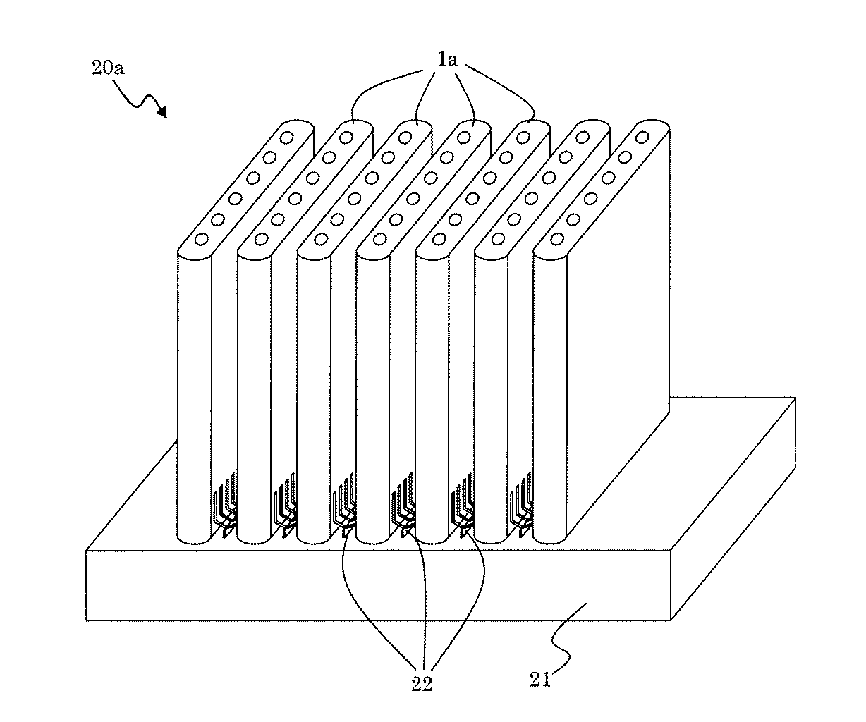
(横縞型固体酸化物形燃料電池バンドル)
図5は、本実施形態にかかるセルスタック1aの一端側を、ガス流路12に燃料ガスを供給するためのガスマニホールド21上に、セルスタック1aが面平行となるように、等間隔で複数本配列し、これら各セルスタック1aの間に、櫛歯状のスタック間接続部材22を配置してなるバンドル20aの一例を示している。
バンドル20aを形成することで、配列されたすべてのセルスタック1aをスタック間接続部材22を用いて電気的に直列に接続でき、効率よく所望の発電量を得ることができる。なお、セルスタック1aの本数は、所望の発電量に応じて適宜調整すればよい。
(Horizontal stripe solid oxide fuel cell bundle)
FIG. 5 shows that one end side of the cell stack 1a according to the present embodiment is placed on the
By forming the
バンドル20aにおいて、各セルスタック1aは、ガスマニホールド21に、例えば、絶縁性の接着剤(例えばガラス等)などにより固定されている。なお、ガスマニホールド21は、耐熱性を有する材質で作製すればよく、例えばケイ素、鉄、酸化チタン、酸化アルミニウムなどからなる金属や耐熱性を有するセラミックス等の材質から作製することができる。
In the
(燃料電池)
本発明の燃料電池は、上述したようなバンドル20aを収納容器内に複数収納することにより構成される。それにより、長期信頼性の向上した燃料電池とすることができる。
(Fuel cell)
The fuel cell of the present invention is configured by storing a plurality of
なお、本発明は以上の実施形態に限定されるものではなく、特許請求の範囲に記載の範囲内において、種々の改善や変更が可能である。
例えば、本発明の横縞型固体酸化物形燃料電池セルスタックを説明するにあたり、内側電極層を燃料極層(集電燃料極層13dおよび活性燃料極層13a)とし、外側電極層を空気極層13cとしてなる燃料電池セル13を備え、ガス流路12に燃料ガスを供給する構成からなるタイプのセルスタック1aを用いて説明したが、例えば内側電極層を空気極層とし、外側電極層を燃料極層としてなる燃料電池セルを備え、ガス流路12に酸素含有ガスを供給する構成からなるタイプのセルスタックとすることもできる。この場合に、必要に応じて空気極層を2層構造とすることができる。
In addition, this invention is not limited to the above embodiment, A various improvement and change are possible within the range as described in a claim.
For example, in describing the horizontally-striped solid oxide fuel cell stack of the present invention, the inner electrode layer is a fuel electrode layer (current collecting
以下、実施例及び比較例を挙げて本発明についてさらに詳細に説明するが、本発明は以下の実施例によって限定されるものではない。 EXAMPLES Hereinafter, although an Example and a comparative example are given and this invention is demonstrated further in detail, this invention is not limited by a following example.
<セルスタック1aの作製>
まず、浸漬製造法によりNi含有量が15.0mol%である領域と、Ni含有量が4.0mol%である領域とからなる多孔質支持体成形体を作製した。即ち、多孔質支持体成形体の材料として、平均粒径(D50)が2.8μmのMgO粉末に、NiOおよびY2O3粉末を配合して、上記領域41bのNi含有量となるように混合した。この混合粉末を、ポアー剤と、セルロース系有機バインダーと、水とからなる溶媒に混合し、押出し成形して、内部にガス流路を有する中空の板状形状で、Ni含有量が4.0mol%である扁平状の多孔質支持体成形体を作製し、次いで、これを発電領域とする部分(図3に示す領域41aに該当する部分)を、NiOの水溶液に浸漬することによってNi含有量が15.0mol%である領域とからなる多孔質支持体成形体を作製した。15.0mol%である領域の多孔質支持体成形体の熱膨張係数は、後述する固体電解質層成形体のそれとほぼ一致するように調整した(すなわち11.0×10⁻⁶(1/K))(図3参照)。これを乾燥後、1100℃、4時間で仮焼処理し、長手方向が350mm、幅方向が50mmの多孔質支持体成形体を得た。
<Production of cell stack 1a>
First, a porous support body formed of a region having a Ni content of 15.0 mol% and a region having a Ni content of 4.0 mol% was produced by an immersion manufacturing method. That is, as the material of the porous support molded body, NiO and Y 2 O 3 powder are blended with MgO powder having an average particle diameter (D 50 ) of 2.8 μm so that the Ni content in the region 41b is obtained. Mixed. This mixed powder is mixed with a solvent composed of a pore agent, a cellulosic organic binder, and water, extruded, and formed into a hollow plate shape having a gas flow path therein, with a Ni content of 4.0 mol. % Of a flat porous support body molded body, and then, by immersing a portion where this is a power generation region (a portion corresponding to the region 41a shown in FIG. 3) in a NiO aqueous solution, the Ni content A porous support molded body having a region of 15.0 mol% was produced. The thermal expansion coefficient of the porous support molded body in the region of 15.0 mol% was adjusted so as to substantially coincide with that of the solid electrolyte layer molded body described later (that is, 11.0 × 10 −6 (1 / K)). (See FIG. 3). This was dried and calcined at 1100 ° C. for 4 hours to obtain a porous support molded body having a longitudinal direction of 350 mm and a width direction of 50 mm.
次に、NiO粉末とYSZ粉末とを混合し、これにポアー剤を添加し、アクリル系バインダーとトルエンとを混合して活性燃料極層成形体用のペーストを作製した。同様にして、LaCrO3系酸化物の粉末を用い、インターコネクタ用のペーストを作製した。 Next, NiO powder and YSZ powder were mixed, a pore agent was added thereto, and an acrylic binder and toluene were mixed to prepare a paste for an active fuel electrode layer molded body. Similarly, a paste for an interconnector was prepared using LaCrO 3 oxide powder.
次に、NiO粉末と、Y2O3の希土類元素酸化物とを混合し、これにポアー剤を添加し、アクリル系バインダーとトルエンとを混合してスラリーとし、ドクターブレード法にてスラリーを塗布して乾燥し、集電燃料極層用テープを作製した。この集電燃料極層テープ上に、所定のメッシュ製版を用いて活性燃料極層用およびインターコネクタ用の各ペーストを順次印刷して乾燥し、活性燃料極層成形体およびインターコネクタを形成した(図4(a)参照)。
なお、インターコネクタ成形体および活性燃料極層成形体は、集電燃料極層用テープ上で、300μmの間隙をおいて形成した。
続いて、集電燃料極層用テープを燃料電池セルの形状にあわせて切断し、絶縁部を形成する部分を打ち抜いた(図4(b)参照)。
Next, NiO powder and Y 2 O 3 rare earth element oxide are mixed, a pore agent is added thereto, acrylic binder and toluene are mixed to form a slurry, and the slurry is applied by a doctor blade method. And dried to produce a current collecting fuel electrode layer tape. On the current collecting fuel electrode layer tape, the active fuel electrode layer and interconnector pastes were sequentially printed using a predetermined mesh plate making and dried to form an active fuel electrode layer molded body and an interconnector ( (See FIG. 4 (a)).
The interconnector molded body and the active fuel electrode layer molded body were formed on a current collecting fuel electrode layer tape with a gap of 300 μm.
Subsequently, the current collecting fuel electrode layer tape was cut in accordance with the shape of the fuel cell, and the portion forming the insulating portion was punched (see FIG. 4B).
その後、活性燃料極層成形体およびインターコネクタ成形体が積層された集電燃料極層テープを、前記仮焼した多孔質支持体成形体に、横縞状に長手方向に沿って幅2mmの間隔をあけて複数貼り付けた(図4(c)参照)。 Thereafter, the current collector fuel electrode layer tape in which the active fuel electrode layer molded body and the interconnector molded body are laminated is spaced from the calcined porous support body molded body by a width of 2 mm along the longitudinal direction in a horizontal stripe shape. A plurality of layers were pasted (see FIG. 4C).
次に、この集電燃料極層テープを貼り付けた状態で乾燥し、その後、1200℃で2時間仮焼した。次に、露出したインターコネクタ成形体の表層部に、マスキングテープを貼り付けた(図4(d)参照)。 Next, it dried in the state which affixed this current collection fuel electrode layer tape, and calcined at 1200 degreeC for 2 hours after that. Next, the masking tape was affixed on the surface layer part of the exposed interconnector molded object (refer FIG.4 (d)).
次に、この積層体を、8YSZにアクリル系バインダーとトルエンを加えてスラリーとした固体電解質層成形体用溶液に浸漬し(ディップし)、固体電解質層成形体用溶液から取り出した。このディップにより、外側全面とガス流路内面の一部に固体電解質層成形体が形成されるとともに、隣接セル間である絶縁部の部分にも固体電解質層成形体を設けた(図4(e)参照)。 Next, this laminate was dipped in a solid electrolyte layer molded body solution obtained by adding an acrylic binder and toluene to 8YSZ to form a slurry, and taken out from the solid electrolyte layer molded body solution. By this dipping, a solid electrolyte layer molded body is formed on the entire outer surface and a part of the inner surface of the gas flow path, and a solid electrolyte layer molded body is also provided on the insulating portion between adjacent cells (FIG. 4 (e)). )reference).
この状態で、900℃で2時間仮焼した。仮焼を終えた時点で、マスキングテープおよびマスキングテープ上の不要な固体電解質層成形体を除去した(図4(f)参照)。次に、多孔質支持体成形体上に集電燃料極層成形体、活性燃料極層成形体、インターコネクタ成形体および固体電解質層成形体が積層された状態で、1480℃、2時間の条件で焼成を行った。 In this state, calcination was performed at 900 ° C. for 2 hours. When the calcination was finished, the masking tape and the unnecessary solid electrolyte layer formed body on the masking tape were removed (see FIG. 4F). Next, a current collecting fuel electrode layer molded body, an active fuel electrode layer molded body, an interconnector molded body, and a solid electrolyte layer molded body are laminated on the porous support body molded body at 1480 ° C. for 2 hours. Was fired.
次に、ランタンコバルタイト(LaCoO3)とイソプロピルアルコールとを混合したスラリーを、活性燃料極層成形体に対向する固体電解質層成形体上に印刷して空気極層成形体を形成し、この空気極層成形体を1100℃、2時間の条件で焼き付けて厚さ50μmの空気極層を形成した(図4(g)参照)。 Next, a slurry obtained by mixing lanthanum cobaltite (LaCoO 3 ) and isopropyl alcohol is printed on a solid electrolyte layer molded body facing the active fuel electrode layer molded body to form an air electrode layer molded body. The polar layered product was baked at 1100 ° C. for 2 hours to form an air electrode layer having a thickness of 50 μm (see FIG. 4G).
最後に、ランタンコバルタイト(LaCoO3)とイソプロピルアルコールとを混合したスラリーを、空気極層上から隣接する燃料電池セルのインターコネクタ上にかけて印刷し、1000℃、4時間の条件で焼き付けて、セル接続材を形成し、実施例のセルスタックを得た(図4(h)参照)。 Finally, a slurry obtained by mixing lanthanum cobaltite (LaCoO 3 ) and isopropyl alcohol is printed from the air electrode layer onto the interconnector of the adjacent fuel cell, and baked at 1000 ° C. for 4 hours. A connecting material was formed to obtain a cell stack of the example (see FIG. 4 (h)).
(比較例)
多孔質支持体成形体全体のNi含有量が15.0mol%である多孔質支持体成形体を作製した他は、実施例1と同様にして、比較例のセルスタックを得た。
(Comparative example)
A cell stack of a comparative example was obtained in the same manner as in Example 1 except that a porous support molded body having a Ni content of 15.0 mol% in the entire porous support molded body was produced.
<評価試験>
実施例及び比較例で得られた各セルスタックについて、900℃昇降温サイクル試験を行って、それぞれの耐久性を調べた。試験方法は、以下の通りである。
<Evaluation test>
About each cell stack obtained by the Example and the comparative example, the 900 degreeC heating / cooling cycle test was done, and each durability was investigated. The test method is as follows.
(900℃昇降温サイクル試験)
収納容器内にセルスタックを収納し、燃料ガスとしてN2およびH2を、セルスタック内のガス流路内にそれぞれN2:1.67L/分、H2:0.42L/分の流量で流し、さらに空気をセルスタック外面に流量48L/minで流しながら、収納容器外部から加熱し、収納容器内の温度を室温から500℃/時の昇温速度で900℃まで昇温させた。900℃到達後に、空気流量はそのまま保ち、N2の供給を止め、H2流量を0.644L/分に増量したガス噴出下で30分間保持した。その後、昇温時と同様のガス噴出下で、500℃/時の降温速度で降温し、室温(50℃程度)まで温度が下がった時点を1サイクルとした。そして、上記セルスタックの多孔質支持体の燃料ガス排出口である他端側の端部及び燃料ガス排出口近傍のガス流路内面を被覆している固体電解質層が破壊に至るサイクル数を調べた。
(900 ° C heating / cooling cycle test)
The cell stack is stored in the storage container, and N 2 and H 2 are used as fuel gases, and the flow rates of N 2 are 1.67 L / min and H 2 are 0.42 L / min. Then, the air was heated from the outside of the storage container while flowing air to the outer surface of the cell stack at a flow rate of 48 L / min, and the temperature inside the storage container was raised from room temperature to 900 ° C. at a temperature increase rate of 500 ° C./hour. After reaching 900 ° C., the air flow rate was kept as it was, N 2 supply was stopped, and the H 2 flow rate was increased to 0.644 L / min and held for 30 minutes. Thereafter, the temperature was lowered at a rate of temperature reduction of 500 ° C./hour under the same gas ejection as that at the time of temperature increase, and the time when the temperature dropped to room temperature (about 50 ° C.) was defined as one cycle. Then, the number of cycles in which the solid electrolyte layer covering the end portion on the other end side which is the fuel gas discharge port of the porous support of the cell stack and the gas flow path inner surface in the vicinity of the fuel gas discharge port is destroyed is examined. It was.
上記試験の結果を表1に示す。
表1に示した通り、非発電領域の少なくとも先端部における多孔質支持体のNi含有量が、発電領域における多孔質支持体のNi含有量よりも少なくした実施例のセルスタックにおいては、多孔質支持体全体のNi含有量を同じにした比較例のセルスタックに比べて、900℃昇降温サイクル試験において、多孔質支持体の燃料ガス排出口側の端部を被覆している固体電解質層が破壊に至るまでの回数を向上することができた。それゆえ、非発電領域の少なくとも先端部における多孔質支持体のNi含有量が、発電領域における多孔質支持体のNi含有量よりも少なくすることで、固体電解質層の破壊を抑制することができることが確認できた。 As shown in Table 1, in the cell stack of the example in which the Ni content of the porous support at least at the tip of the non-power generation region was smaller than the Ni content of the porous support in the power generation region, the porous Compared to the cell stack of the comparative example in which the Ni content of the entire support is the same, in the 900 ° C. temperature increase / decrease cycle test, the solid electrolyte layer covering the end on the fuel gas discharge port side of the porous support is The number of times to destruction was improved. Therefore, the breakdown of the solid electrolyte layer can be suppressed by making the Ni content of the porous support at least at the tip of the non-power generation region smaller than the Ni content of the porous support in the power generation region. Was confirmed.
1a 横縞型固体酸化物形燃料電池セルスタック
11 多孔質支持体
11a Ni含有量が多い多孔質支持体
11b Ni含有量が少ない多孔質支持体
11c 非発電領域の多孔質支持体11b以外の多孔質支持体
12 ガス流路
13 燃料電池セル
13a 活性燃料極層
13b 固体電解質層
13c 空気極層
13d 集電燃料極層
17 セル間接続部材
17a インターコネクタ
17b セル接続材
18 端面
20a 横縞型固体酸化物形燃料電池バンドル
21 ガスマニホールド
22 スタック間接続部材
25 非発電領域
26 発電領域
27 燃料ガス排出口
41 多孔質支持体成形体
41a Ni含有量が多い多孔質支持体成形体
41b Ni含有量が少ない多孔質支持体成形体
43a 活性燃料極層成形体
43b 固体電解質層成形体
43c 空気極層成形体
43d 集電燃料極層用テープ
46 集電燃料極層用テープ
47a インターコネクタ
47b セル接続材
48 マスキングテープ
DESCRIPTION OF SYMBOLS 1a Horizontal stripe type solid oxide
Claims (6)
前記非発電領域の少なくとも先端部における前記多孔質支持体のNiのNiO換算での含有量が、前記発電領域における前記多孔質支持体のNiのNiO換算での含有量よりも少ないことを特徴とする横縞型固体酸化物形燃料電池セルスタック。 A gas flow path for flowing fuel gas along the longitudinal direction is provided inside, and has a fuel gas introduction port for the gas flow path on one end side and a fuel gas discharge port for the gas flow path on the other end side. A fuel cell having a multilayer structure in which an inner electrode layer, a solid electrolyte layer, and an outer electrode layer are sequentially laminated on an electrically insulating porous support containing Ni and / or NiO. A horizontal stripe in which a plurality of power generation regions are formed along the longitudinal direction of the porous support, and the other end of the porous support is covered with a solid electrolyte layer to form a non-power generation region. Type solid oxide fuel cell stack,
The content of Ni in NiO conversion of the porous support in at least the tip of the non-power generation region is less than the content of Ni in NiO conversion of the porous support in the power generation region, Horizontally striped solid oxide fuel cell stack.
Priority Applications (1)
| Application Number | Priority Date | Filing Date | Title |
|---|---|---|---|
| JP2010143026A JP5401405B2 (en) | 2010-06-23 | 2010-06-23 | Horizontally Striped Solid Oxide Fuel Cell Stack, Horizontally Striped Solid Oxide Fuel Cell Bundle, and Fuel Cell |
Applications Claiming Priority (1)
| Application Number | Priority Date | Filing Date | Title |
|---|---|---|---|
| JP2010143026A JP5401405B2 (en) | 2010-06-23 | 2010-06-23 | Horizontally Striped Solid Oxide Fuel Cell Stack, Horizontally Striped Solid Oxide Fuel Cell Bundle, and Fuel Cell |
Publications (2)
| Publication Number | Publication Date |
|---|---|
| JP2012009228A JP2012009228A (en) | 2012-01-12 |
| JP5401405B2 true JP5401405B2 (en) | 2014-01-29 |
Family
ID=45539557
Family Applications (1)
| Application Number | Title | Priority Date | Filing Date |
|---|---|---|---|
| JP2010143026A Active JP5401405B2 (en) | 2010-06-23 | 2010-06-23 | Horizontally Striped Solid Oxide Fuel Cell Stack, Horizontally Striped Solid Oxide Fuel Cell Bundle, and Fuel Cell |
Country Status (1)
| Country | Link |
|---|---|
| JP (1) | JP5401405B2 (en) |
Families Citing this family (2)
| Publication number | Priority date | Publication date | Assignee | Title |
|---|---|---|---|---|
| JP5600819B1 (en) * | 2013-04-19 | 2014-10-08 | 日本碍子株式会社 | Fuel cell |
| JP2015128001A (en) * | 2013-12-27 | 2015-07-09 | Toto株式会社 | Solid oxide fuel cell |
Family Cites Families (7)
| Publication number | Priority date | Publication date | Assignee | Title |
|---|---|---|---|---|
| JP3609146B2 (en) * | 1995-03-31 | 2005-01-12 | 株式会社フジクラ | Fuel electrode of solid oxide fuel cell |
| JP4268422B2 (en) * | 2003-02-26 | 2009-05-27 | 京セラ株式会社 | Fuel cell and fuel cell |
| JP4544975B2 (en) * | 2004-07-21 | 2010-09-15 | 京セラ株式会社 | Fuel cell and fuel cell |
| JP4767532B2 (en) * | 2004-12-16 | 2011-09-07 | 東京瓦斯株式会社 | Horizontally striped solid oxide fuel cell |
| JP4931365B2 (en) * | 2005-04-20 | 2012-05-16 | 京セラ株式会社 | Support substrate for fuel cell, fuel cell, and fuel cell |
| JP4718959B2 (en) * | 2005-09-29 | 2011-07-06 | 京セラ株式会社 | Horizontal stripe fuel cell |
| JP5192723B2 (en) * | 2007-05-10 | 2013-05-08 | 京セラ株式会社 | Horizontally-striped fuel cell and fuel cell |
-
2010
- 2010-06-23 JP JP2010143026A patent/JP5401405B2/en active Active
Also Published As
| Publication number | Publication date |
|---|---|
| JP2012009228A (en) | 2012-01-12 |
Similar Documents
| Publication | Publication Date | Title |
|---|---|---|
| JP5457954B2 (en) | Horizontally Striped Solid Oxide Fuel Cell Stack, Horizontally Striped Solid Oxide Fuel Cell Bundle, and Fuel Cell | |
| JP5175527B2 (en) | Cell stack and fuel cell | |
| JP5295262B2 (en) | FUEL CELL, FUEL CELL MODULE, FUEL CELL DEVICE, AND FUEL CELL CELL MANUFACTURING METHOD | |
| JP5080951B2 (en) | Horizontal stripe fuel cell stack and fuel cell | |
| JP4718959B2 (en) | Horizontal stripe fuel cell | |
| JP5118865B2 (en) | Horizontally-striped fuel cell and method for producing the same | |
| JP5444022B2 (en) | Horizontally-striped solid oxide fuel cell stack and fuel cell | |
| JP2007134230A (en) | Cell for fuel cell, cell stack of fuel cell, and fuel cell | |
| JP5328439B2 (en) | Fuel cell, fuel cell stack device, fuel cell module and fuel cell device | |
| JP5437169B2 (en) | Horizontally Striped Solid Oxide Fuel Cell Stack, Horizontally Striped Solid Oxide Fuel Cell Bundle, and Fuel Cell | |
| JP5677632B1 (en) | Solid oxide cell, cell stack device and module, and module storage device | |
| JP5192723B2 (en) | Horizontally-striped fuel cell and fuel cell | |
| JP5281950B2 (en) | Horizontally-striped fuel cell stack, manufacturing method thereof, and fuel cell | |
| JP2004253376A (en) | Fuel battery cell and method for manufacturing same, and fuel battery | |
| JP4851692B2 (en) | Solid electrolyte fuel cell stack, bundle and fuel cell | |
| JP2004265734A (en) | Fuel battery cell | |
| JP5132879B2 (en) | Horizontal stripe fuel cell and fuel cell | |
| JP2005093241A (en) | Solid oxide fuel cell | |
| JP2012038586A (en) | Structure of fuel cell | |
| JP2012014850A (en) | Lateral stripe type solid oxide fuel battery cell stack, lateral stripe type solid oxide fuel battery bundle, and fuel battery | |
| JP4798947B2 (en) | Fuel cell, cell stack and fuel cell | |
| JP5179131B2 (en) | Horizontal stripe fuel cell and fuel cell | |
| JP5401405B2 (en) | Horizontally Striped Solid Oxide Fuel Cell Stack, Horizontally Striped Solid Oxide Fuel Cell Bundle, and Fuel Cell | |
| JP5198108B2 (en) | Horizontally-striped solid oxide fuel cell stack and fuel cell | |
| JP4925574B2 (en) | Fuel cell and fuel cell |
Legal Events
| Date | Code | Title | Description |
|---|---|---|---|
| A621 | Written request for application examination |
Free format text: JAPANESE INTERMEDIATE CODE: A621 Effective date: 20130213 |
|
| TRDD | Decision of grant or rejection written | ||
| A977 | Report on retrieval |
Free format text: JAPANESE INTERMEDIATE CODE: A971007 Effective date: 20130925 |
|
| A01 | Written decision to grant a patent or to grant a registration (utility model) |
Free format text: JAPANESE INTERMEDIATE CODE: A01 Effective date: 20131001 |
|
| A61 | First payment of annual fees (during grant procedure) |
Free format text: JAPANESE INTERMEDIATE CODE: A61 Effective date: 20131028 |
|
| R150 | Certificate of patent or registration of utility model |
Ref document number: 5401405 Country of ref document: JP Free format text: JAPANESE INTERMEDIATE CODE: R150 Free format text: JAPANESE INTERMEDIATE CODE: R150 |
|
| R250 | Receipt of annual fees |
Free format text: JAPANESE INTERMEDIATE CODE: R250 |
|
| R250 | Receipt of annual fees |
Free format text: JAPANESE INTERMEDIATE CODE: R250 |
|
| R250 | Receipt of annual fees |
Free format text: JAPANESE INTERMEDIATE CODE: R250 |
|
| R250 | Receipt of annual fees |
Free format text: JAPANESE INTERMEDIATE CODE: R250 |
|
| R250 | Receipt of annual fees |
Free format text: JAPANESE INTERMEDIATE CODE: R250 |
|
| R250 | Receipt of annual fees |
Free format text: JAPANESE INTERMEDIATE CODE: R250 |
|
| R250 | Receipt of annual fees |
Free format text: JAPANESE INTERMEDIATE CODE: R250 |
|
| R250 | Receipt of annual fees |
Free format text: JAPANESE INTERMEDIATE CODE: R250 |