JP5399168B2 - Motorcycle - Google Patents
Motorcycle Download PDFInfo
- Publication number
- JP5399168B2 JP5399168B2 JP2009194735A JP2009194735A JP5399168B2 JP 5399168 B2 JP5399168 B2 JP 5399168B2 JP 2009194735 A JP2009194735 A JP 2009194735A JP 2009194735 A JP2009194735 A JP 2009194735A JP 5399168 B2 JP5399168 B2 JP 5399168B2
- Authority
- JP
- Japan
- Prior art keywords
- air cleaner
- cleaner case
- plate
- lid
- seat
- Prior art date
- Legal status (The legal status is an assumption and is not a legal conclusion. Google has not performed a legal analysis and makes no representation as to the accuracy of the status listed.)
- Expired - Fee Related
Links
Images


Classifications
-
- F—MECHANICAL ENGINEERING; LIGHTING; HEATING; WEAPONS; BLASTING
- F02—COMBUSTION ENGINES; HOT-GAS OR COMBUSTION-PRODUCT ENGINE PLANTS
- F02M—SUPPLYING COMBUSTION ENGINES IN GENERAL WITH COMBUSTIBLE MIXTURES OR CONSTITUENTS THEREOF
- F02M35/00—Combustion-air cleaners, air intakes, intake silencers, or induction systems specially adapted for, or arranged on, internal-combustion engines
- F02M35/02—Air cleaners
- F02M35/024—Air cleaners using filters, e.g. moistened
- F02M35/02475—Air cleaners using filters, e.g. moistened characterised by the shape of the filter element
- F02M35/02491—Flat filter elements, e.g. rectangular
-
- B—PERFORMING OPERATIONS; TRANSPORTING
- B62—LAND VEHICLES FOR TRAVELLING OTHERWISE THAN ON RAILS
- B62J—CYCLE SADDLES OR SEATS; AUXILIARY DEVICES OR ACCESSORIES SPECIALLY ADAPTED TO CYCLES AND NOT OTHERWISE PROVIDED FOR, e.g. ARTICLE CARRIERS OR CYCLE PROTECTORS
- B62J37/00—Arrangements of fuel supply lines, taps, or the like, on motor cycles or engine-assisted cycles
-
- F—MECHANICAL ENGINEERING; LIGHTING; HEATING; WEAPONS; BLASTING
- F02—COMBUSTION ENGINES; HOT-GAS OR COMBUSTION-PRODUCT ENGINE PLANTS
- F02M—SUPPLYING COMBUSTION ENGINES IN GENERAL WITH COMBUSTIBLE MIXTURES OR CONSTITUENTS THEREOF
- F02M35/00—Combustion-air cleaners, air intakes, intake silencers, or induction systems specially adapted for, or arranged on, internal-combustion engines
- F02M35/02—Air cleaners
- F02M35/0201—Housings; Casings; Frame constructions; Lids; Manufacturing or assembling thereof
- F02M35/0202—Manufacturing or assembling; Materials for air cleaner housings
- F02M35/0203—Manufacturing or assembling; Materials for air cleaner housings by using clamps, catches, locks or the like, e.g. for disposable plug-in filter cartridges
-
- F—MECHANICAL ENGINEERING; LIGHTING; HEATING; WEAPONS; BLASTING
- F02—COMBUSTION ENGINES; HOT-GAS OR COMBUSTION-PRODUCT ENGINE PLANTS
- F02M—SUPPLYING COMBUSTION ENGINES IN GENERAL WITH COMBUSTIBLE MIXTURES OR CONSTITUENTS THEREOF
- F02M35/00—Combustion-air cleaners, air intakes, intake silencers, or induction systems specially adapted for, or arranged on, internal-combustion engines
- F02M35/16—Combustion-air cleaners, air intakes, intake silencers, or induction systems specially adapted for, or arranged on, internal-combustion engines characterised by use in vehicles
- F02M35/162—Motorcycles; All-terrain vehicles, e.g. quads, snowmobiles; Small vehicles, e.g. forklifts
-
- F—MECHANICAL ENGINEERING; LIGHTING; HEATING; WEAPONS; BLASTING
- F02—COMBUSTION ENGINES; HOT-GAS OR COMBUSTION-PRODUCT ENGINE PLANTS
- F02M—SUPPLYING COMBUSTION ENGINES IN GENERAL WITH COMBUSTIBLE MIXTURES OR CONSTITUENTS THEREOF
- F02M35/00—Combustion-air cleaners, air intakes, intake silencers, or induction systems specially adapted for, or arranged on, internal-combustion engines
- F02M35/02—Air cleaners
- F02M35/04—Air cleaners specially arranged with respect to engine, to intake system or specially adapted to vehicle; Mounting thereon ; Combinations with other devices
Description
本発明は、エアクリーナケースを備えた自動二輪車に関する。 The present invention relates to a motorcycle including an air cleaner case.
従来、自動二輪車の吸気装置において、シート下方にエアクリーナケースを配置し、シートの下方かつエアクリーナケースの上面に、取外し可能なメンテナンスリッド(エアクリーナカバー)を設け、このメンテナンスリッドからエアクリーナケースに板状のエレメントを鉛直方向に挿入すると共に、エレメントを鉛直な向きで固定するものが知られている(例えば、特許文献1参照)。
しかしながら、上記従来のエアクリーナケースでは、エレメントが鉛直な向きで固定されるため、エレメントの面積を確保しようとするとエレメントが縦長になり、エアクリーナケースを高さ方向に大型化する必要があった。このため、シート高の低減が困難であり、また、大型化されたエアクリーナケースをエンジンに近接して配置することが難しく、吸気装置をエンジンに近接させてエンジン特性の向上を図ることが難しかった。 However, in the above conventional air cleaner case, the element is fixed in a vertical direction. Therefore, when attempting to secure the area of the element, the element becomes vertically long, and the air cleaner case needs to be enlarged in the height direction. For this reason, it is difficult to reduce the seat height, it is difficult to arrange the enlarged air cleaner case close to the engine, and it is difficult to improve the engine characteristics by bringing the intake device close to the engine. .
本発明は、上述した事情に鑑みてなされたものであり、自動二輪車において、エアクリーナケースをコンパクトに設けることで、シート高を低減すると共に、エアクリーナケースをエンジンに近接配置できるようにすることを目的とする。 The present invention has been made in view of the above-described circumstances, and an object of the present invention is to provide a compact air cleaner case in a motorcycle, thereby reducing the seat height and allowing the air cleaner case to be disposed close to the engine. And
上述課題を解決するため、本発明は、前輪(WF)を操舵可能に保持すると共に、後輪(WR)を揺動可能に保持する車体フレーム(11)と、前記車体フレーム(11)の前部上方に配置される燃料タンク(35)と、該燃料タンク(35)の後方かつ前記車体フレーム(11)の上方に配置されるシート(36)と、前記燃料タンク(35)の下方かつ前記車体フレーム(11)の下方に懸架される内燃機関(12)と、取り込んだ外気を清浄化して前記内燃機関(12)に供給するエアクリーナケース(61)と、該エアクリーナケース(61)内に配置される板状エレメント(70)と、前記エアクリーナケース(61)の一部を形成し、前記板状エレメント(70)の着脱の際に利用されるメンテナンスリッド(72)とを備えた自動二輪車において、前記内燃機関(12)はシリンダの軸が前傾して設けられる4サイクルエンジンであり、前記エアクリーナケース(61)がシリンダの上部に設けられるシリンダヘッド(43)の後方で前記燃料タンク(35)下方に配置されると共に、上下2分割で構成され、上部エアクリーナケース(64)がクリーンサイドに、下部エアクリーナケース(65)がダーティーサイドに形成され、前記エアクリーナケース(61)の吸気ダクト(67)は前記メンテナンスリッド(72)の下方に設けられ、前記上部エアクリーナケース(64)に、前記内燃機関(12)へ吸気を供給するコネクティングチューブ用開口(63)が形成され、前記下部エアクリーナケース(65)に、外気を前記エアクリーナケース(61)に導入する吸気ダクト用開口(66)が形成され、前記板状エレメント(70)及び前記メンテナンスリッド(72)が前記下部エアクリーナケース(65)に配置され、前記上部エアクリーナケース(64)と前記下部エアクリーナケース(65)との分割面にエレメントホルダ(68)を狭持し、前記エレメントホルダ(68)の下部に前記板状エレメント(70)を保持するエレメントガイド部(91)を形成し、車両側面視で、前記板状エレメント(70)がその清浄化面を上下方向を指向して後ろ上がりに傾斜して配置され、前記シート(36)の前端の下方には、前記シート(36)を支持する左右のシートレール(20)の間に、他の部品が配置されない空間(K)が形成されており、前記メンテナンスリッド(72)が、空間(K)に臨んで設けられるとともに、前記シート(36)を取り外して前記板状エレメント(70)を引き出し可能に前記シート(36)の下方で前記シート(36)に対向して設けられ、前記エレメントガイド部(91)は、前記板状エレメント(70)の下方で、前記板状エレメント(70)の傾斜角度よりも小さい角度で後上がりに形成されるとともに、前記板状エレメント(70)を押し込み方向及び空間(K)側への引き出し方向にガイドするガイド部(91B)を備え、前記メンテナンスリッド(72)に前記エアクリーナケース(61)の内側に突出するリッド側ガイド部(72B)が形成され、当該リッド側ガイド部(72B)は、前記メンテナンスリッド(72)が前記エアクリーナケース(61)に固定された状態で、前記板状エレメント(70)を固定位置まで押し上げるように形成され、前記エレメントガイド部(91)は、前記リッド側ガイド部(72B)の押し上げが解除されて前記板状エレメント(70)を取り外す際に自重で落下する前記板状エレメント(70)を保持することを特徴とする。
この構成によれば、板状エレメントが後ろ上がりに傾斜して配置され、板状エレメントの大きさがエアクリーナケースの高さ方向の大きさに影響しないため、エアクリーナケースを高さ方向にコンパクトに配置できる。これにより、エアクリーナケースをエンジンに近接させて配置できるとともに、シート高を低減できる。また、メンテナンスリッドが燃料タンクの後方のシートに対向して設けられたため、エアクリーナケースをエンジンに近接させて配置した場合においても燃料タンクが邪魔になることが無く、シートの側から板状エレメントを着脱してメンテナンスをすることができる。さらに、シートの下方はメンテナンスリッドが臨む空間が形成されるだけであるため、シート高を低減させて自動二輪車の取り廻し性を向上できる。
また、上下2分割で構成されたエアクリーナケースの下部エアクリーナケースに板状エレメントを配置したため、板状エレメントの着脱の際に、板状エレメントに付着した塵埃が、上部エアクリーナケース側、すなわち、クリーンサイド側に落ちることを防止でき、メンテナンス性を向上できる。また、下部エアクリーナケース側、すなわち、外気が導入されるダーティーサイド側にメンテナンスリッドを配置したため、メンテナンスリッドと下部エアクリーナケースの間の気密性の管理が比較的容易になり、生産性を向上できる。
また、板状エレメントをメンテナンスリッドから挿入する際に、エレメントホルダのエレメントガイド部を利用できるため、板状エレメントの着脱性を向上できる。
また、メンテナンスリッドをエアクリーナケースに固定すると、リッド側ガイド部によって板状エレメントが押し上げられて板状エレメントも同時に固定されるため、メンテナンス性を向上できる。また、メンテナンスリッドを取り外すと板状エレメントが自重によりエレメントガイド部の位置まで下がることが可能なため、板状エレメントが抜き易くなる。
In order to solve the above-described problems, the present invention provides a vehicle body frame (11) that holds a front wheel (WF) in a steerable manner and holds a rear wheel (WR) in a swingable manner, and a front of the vehicle body frame (11). A fuel tank (35) disposed above the part, a seat (36) disposed behind the fuel tank (35) and above the vehicle body frame (11), below the fuel tank (35) and the An internal combustion engine (12) suspended below the vehicle body frame (11), an air cleaner case (61) for cleaning the taken-in outside air and supplying it to the internal combustion engine (12), and an air cleaner case (61) And a maintenance lid (72) that forms a part of the air cleaner case (61) and is used when the plate element (70) is attached or detached. In the motorcycle, the internal combustion engine (12) is a four-cycle engine in which a cylinder shaft is inclined forward, and the fuel is disposed behind a cylinder head (43) in which the air cleaner case (61) is provided in an upper portion of the cylinder. The upper air cleaner case (64) is formed on the clean side and the lower air cleaner case (65) is formed on the dirty side, and is arranged below the tank (35) and divided into upper and lower parts, and the air cleaner case (61) is inhaled. A duct (67) is provided below the maintenance lid (72), and an opening (63) for a connecting tube for supplying intake air to the internal combustion engine (12) is formed in the upper air cleaner case (64). The outside air is guided to the air cleaner case (61) to the air cleaner case (65). An intake duct opening (66) is formed, the plate element (70) and the maintenance lid (72) are disposed in the lower air cleaner case (65), and the upper air cleaner case (64) and the lower air cleaner case An element guide (91) for holding the plate-like element (70) is formed at the lower part of the element holder (68) by sandwiching the element holder (68) on the split surface with (65), and the vehicle side view The plate-like element (70) is disposed with its cleaning surface inclined in the up-down direction and directed upward, and supports the sheet (36) below the front end of the sheet (36). A space (K) in which no other parts are arranged is formed between the left and right seat rails (20), and the maintenance lid (72) is a space (K ), The sheet (36) is removed, and the plate-like element (70) can be pulled out so as to face the sheet (36) below the sheet (36), and the element guide The part (91) is formed rearwardly at a lower angle than the inclination angle of the plate element (70) below the plate element (70) and pushes the plate element (70) in the pushing direction. And a guide portion (91B) that guides in the pulling direction toward the space (K) side, and a lid-side guide portion (72B) that protrudes inside the air cleaner case (61) is formed on the maintenance lid (72). The lid side guide portion (72B) is a state where the maintenance lid (72) is fixed to the air cleaner case (61). The element guide portion (91) is formed so as to push up the lid-shaped guide portion (72B) and the plate-like element (70) is removed when the plate-like element (70) is removed. The plate-like element (70) that drops is retained .
According to this configuration, the plate-like element is arranged to be inclined backward and the size of the plate-like element does not affect the size of the air cleaner case in the height direction, so the air cleaner case is arranged compactly in the height direction. it can. As a result, the air cleaner case can be disposed close to the engine and the seat height can be reduced. In addition, since the maintenance lid is provided facing the seat behind the fuel tank, the fuel tank does not get in the way even when the air cleaner case is placed close to the engine, and the plate-like element is inserted from the seat side. It can be attached and detached for maintenance. Furthermore, since only a space where the maintenance lid faces is formed below the seat, the seat height can be reduced and the handling of the motorcycle can be improved.
In addition, since the plate-like element is arranged in the lower air cleaner case of the air cleaner case that is divided into the upper and lower parts, dust attached to the plate-like element is attached to the upper air cleaner case side, that is, the clean side when the plate-like element is attached or detached. Can be prevented from falling to the side, and maintainability can be improved. Further, since the maintenance lid is arranged on the lower air cleaner case side, that is, on the dirty side side where outside air is introduced, the airtightness management between the maintenance lid and the lower air cleaner case becomes relatively easy, and the productivity can be improved.
Moreover, since the element guide part of an element holder can be utilized when inserting a plate-shaped element from a maintenance lid, the detachability of a plate-shaped element can be improved.
Further, when the maintenance lid is fixed to the air cleaner case, the plate-like element is pushed up by the lid-side guide portion and the plate-like element is also fixed at the same time, so that maintainability can be improved. Further, when the maintenance lid is removed, the plate-like element can be lowered to the position of the element guide portion by its own weight, so that the plate-like element can be easily removed.
さらに、前記メンテナンスリッド(72)は、その上部に引っ掛け部(72C)を有すると共に、下部に締結部(72D)を有しても良い。
この場合、上部に引っ掛け部を設け、上部を締結等により固定しないため、上部を支点にしてメンテナンスリッドを回動させながらエアーナケースに取り付けできるため、リッド側ガイド部で板状エレメントを持ち上げることができ、板状エレメントを固定位置まで押し上げることができる。また、メンテナンスリッドの上部に引っ掛け部を設けたため、上部に締結部品を設ける必要が無く、締結部品の点数を削減して生産性の向上及び軽量化を図ることができる。
Further, the maintenance lid (72) may have a hooking portion (72C) at the upper portion and a fastening portion (72D) at the lower portion.
In this case, since the upper part is provided with a hook and the upper part is not fixed by fastening, etc., the maintenance lid can be attached to the air case while rotating with the upper part as a fulcrum, so the plate-like element is lifted by the lid side guide part. The plate-like element can be pushed up to a fixed position. Further, since the hook portion is provided on the upper part of the maintenance lid, it is not necessary to provide a fastening part on the upper part, and the number of fastening parts can be reduced to improve the productivity and reduce the weight.
さらにまた、前記上部エアクリーナケース(64)に、前記エアクリーナケース(61)を前記車体フレーム(11)へ固定する全てのケース側締結部(75)を形成すると共に、前記エアクリーナケース(61)が固定される前記車体フレーム(11)側のフレーム側締結部(20A)は、該車体フレーム(11)の上面に配置されても良い。
この場合、エアクリーナケースの車体フレームへの全てのケース側締結部を上部エアクリーナケースに一体的に形成するため、各ケース側締結部の位置精度を向上させることができ、生産性が向上する。また、車体フレームの上方側からケース側締結部を締め付けてエアクリーナケースを組み付けできるため、組み付け作業が容易になり、さらに生産性が向上する。
Furthermore, all the case side fastening portions (75) for fixing the air cleaner case (61) to the vehicle body frame (11 ) are formed in the upper air cleaner case (64) , and the air cleaner case (61) is fixed. The vehicle body frame (11) side frame side fastening portion (20A) may be disposed on the upper surface of the vehicle body frame (11) .
In this case, since all the case side fastening portions to the body frame of the air cleaner case are integrally formed with the upper air cleaner case, the positional accuracy of each case side fastening portion can be improved, and the productivity is improved. Further, since the air cleaner case can be assembled by tightening the case side fastening portion from the upper side of the body frame, the assembling work is facilitated and the productivity is further improved.
また、前記コネクティングチューブ用開口(63)に接続されるコネクティングチューブ(62)と対向する前記上部エアクリーナケース(64)の壁部(64D)を球状に形成しても良い。
この場合、エンジンの吸気負圧が作用する上部エアクリーナケースの壁部を球状に形成し、壁部の剛性が増加したため、吸気音を低減できる。
また、前記車体フレーム(11)は少なくとも左右一対のフレーム部材(20)で構成され、前記燃料タンク(35)は、後部に後面視でアーチ状に形成された後方締結部(78)を備え、該後方締結部(78)の車幅方向両端部を介して左右一対の前記フレーム部材(20)に固定されても良い。
この場合、燃料タンクの後部にアーチ状の後方締結部を備えたため、燃料タンクの後方にメンテナンスリッドを配置する空間を確保できる。また、後方締結部は、左右一対のフレーム部材を連結する部材としても機能するため、フレーム部材の強度及び剛性を向上できる。
The wall portion (64D) of the upper air cleaner case (64) facing the connecting tube (62) connected to the opening (63) for the connecting tube may be formed in a spherical shape.
In this case, the wall portion of the upper air cleaner case where the intake negative pressure of the engine acts is formed in a spherical shape and the rigidity of the wall portion is increased, so that the intake noise can be reduced.
The vehicle body frame (11) includes at least a pair of left and right frame members (20) , and the fuel tank (35) includes a rear fastening portion (78) formed in an arch shape in the rear view, You may fix to the said left-right paired said frame member (20) via the vehicle width direction both ends of this back fastening part (78) .
In this case, since the rear portion of the fuel tank is provided with the arch-shaped rear fastening portion, it is possible to secure a space for arranging the maintenance lid behind the fuel tank. Further, since the rear fastening portion also functions as a member that connects the pair of left and right frame members, the strength and rigidity of the frame member can be improved.
本発明に係る自動二輪車では、板状エレメントが、後ろ上がりに傾斜して配置されてエアクリーナケースの高さ方向の大きさに影響しないため、エアクリーナケースを高さ方向にコンパクトに配置できる。これにより、エアクリーナケースをエンジンに近接させて配置できるとともに、シート高を低減できる。また、メンテナンスリッドがシートに対向して設けられたため、エアクリーナケースをエンジンに近接させて配置した場合においても燃料タンクが邪魔になることが無く、シートの側から板状エレメントを着脱してメンテナンスをすることができる。さらに、シートの下方はメンテナンスリッドが臨む空間が形成されるだけであるため、シート高を低減させて自動二輪車の取り廻し性を向上できる。 In the motorcycle according to the present invention, since the plate-like elements are arranged to be inclined rearward and do not affect the height direction of the air cleaner case, the air cleaner case can be arranged compactly in the height direction. As a result, the air cleaner case can be disposed close to the engine and the seat height can be reduced. In addition, since the maintenance lid is provided facing the seat, the fuel tank does not get in the way even when the air cleaner case is placed close to the engine, and maintenance can be performed by removing the plate element from the seat side. can do. Furthermore, since only a space where the maintenance lid faces is formed below the seat, the seat height can be reduced and the handling of the motorcycle can be improved.
また、下部エアクリーナケースに板状エレメントを配置したため、板状エレメントに付着した塵埃が、上部エアクリーナケース側のクリーンサイド側に落ちることを防止でき、メンテナンス性を向上できる。また、ダーティーサイドである下部エアクリーナケース側にメンテナンスリッドを配置したため、メンテナンスリッドと下部エアクリーナケースとの間の気密性の管理が比較的容易になり、生産性を向上できる。
また、エレメントホルダのエレメントガイド部を利用して板状エレメントを挿入できるため、板状エレメントの着脱性を向上できる。
In addition, since the plate-like element is arranged in the lower air cleaner case, dust attached to the plate-like element can be prevented from falling to the clean side on the upper air cleaner case side, and the maintainability can be improved. Further, since the maintenance lid is arranged on the lower air cleaner case side which is the dirty side, the airtightness management between the maintenance lid and the lower air cleaner case becomes relatively easy, and the productivity can be improved.
Moreover, since the plate-like element can be inserted using the element guide portion of the element holder, the detachability of the plate-like element can be improved.
さらに、メンテナンスリッドを固定すると、リッド側ガイド部に押し上げられて板状エレメントも同時に固定されるため、メンテナンス性を向上できる。また、メンテナンスリッドを取り外すと板状エレメントが自重によりエレメントガイド部の位置まで下がることが可能なため、板状エレメントが抜き易くなる。
さらにまた、メンテナンスリッドの上部を支点にしてメンテナンスリッドを回動させながらエアーナケースに取り付けでき、リッド側ガイド部で板状エレメントを持ち上げることで、板状エレメントを固定位置まで押し上げることができる。また、メンテナンスリッドの上部に引っ掛け部を設けたため、上部に締結部品を設ける必要が無く、締結部品の点数を削減して生産性の向上及び軽量化を図ることができる。
Furthermore, when the maintenance lid is fixed, the plate-like element is also fixed at the same time by being pushed up by the lid-side guide portion, so that maintainability can be improved. Further, when the maintenance lid is removed, the plate-like element can be lowered to the position of the element guide portion by its own weight, so that the plate-like element can be easily removed.
Furthermore, the maintenance lid can be attached to the air nah case while turning the upper part of the maintenance lid as a fulcrum, and the plate-like element can be pushed up to a fixed position by lifting the plate-like element at the lid-side guide portion. Further, since the hook portion is provided on the upper part of the maintenance lid, it is not necessary to provide a fastening part on the upper part, and the number of fastening parts can be reduced to improve the productivity and reduce the weight.
また、エアクリーナケースの車体フレームへの全てのケース側締結部を上部エアクリーナケースに一体的に形成するため、各ケース側締結部の位置精度を向上させることができ、生産性が向上する。また、車体フレームの上方側からケース側締結部を締め付けてエアクリーナケースを組み付けできるため、組み付け作業が容易になり、さらに生産性が向上する。
さらに、エンジンの吸気負圧が作用する上部エアクリーナケースの壁部を球状に形成し、壁部の剛性が増加したため、吸気音を低減できる。
また、燃料タンクの後部にアーチ状の後方締結部を備えたため、燃料タンクの後方にメンテナンスリッドを配置する空間を確保できる。また、後方締結部は、左右一対のフレーム部材を連結する部材としても機能するため、フレーム部材の強度及び剛性を向上できる。
Moreover, since all the case side fastening parts to the vehicle body frame of the air cleaner case are integrally formed in the upper air cleaner case, the positional accuracy of each case side fastening part can be improved, and the productivity is improved. Further, since the air cleaner case can be assembled by tightening the case side fastening portion from the upper side of the body frame, the assembling work is facilitated and the productivity is further improved.
Furthermore, since the wall portion of the upper air cleaner case where the intake negative pressure of the engine acts is formed in a spherical shape and the rigidity of the wall portion is increased, the intake noise can be reduced.
Further, since the rear portion of the fuel tank is provided with the arch-shaped rear fastening portion, it is possible to secure a space for arranging the maintenance lid behind the fuel tank. Further, since the rear fastening portion also functions as a member that connects the pair of left and right frame members, the strength and rigidity of the frame member can be improved.
以下、本発明の実施の形態に係る車両について図面を参照して説明する。なお、以下の説明で、上下、前後、左右の方向は、車両の運転者から見た方向をいう。
図1は、本発明の実施の形態に係る自動二輪車10の左側面図である。
自動二輪車10は、車体フレーム11の中央部にエンジン12(内燃機関)が配置され、車体フレーム11の前端にフロントフォーク13が操舵可能に支持され、車体フレーム11の後部の下部に上下に揺動可能なスイングアーム14が支持された鞍乗り型の車両である。
Hereinafter, a vehicle according to an embodiment of the present invention will be described with reference to the drawings. In the following description, the up / down, front / rear, and left / right directions are directions seen from the driver of the vehicle.
FIG. 1 is a left side view of a
In the
車体フレーム11は、フロントフォーク13を操舵可能に支持するヘッドパイプ16と、ヘッドパイプ16の上部から後下方に延びる左右一対のメインフレーム17と、ヘッドパイプ16の下部から後下方に延びる左右一対のダウンフレーム18と、車両の前後方向中間部でメインフレーム17の後端から下方に延びる左右一対のセンターフレーム19と、メインフレーム17の後部から後ろ上がりに車両後部へ延びる左右一対のシートレール20(フレーム部材)と、メインフレーム17の上部後端とシートレール20の後端とを連結する左右一対のサブフレーム21と、スイングアーム14とを備えて構成される。
The
また、ヘッドパイプ16の後方及びエンジン12の側方には、メインフレーム17とダウンフレーム18とを連結する補強フレーム22、23がそれぞれ設けられている。さらに、センターフレーム19の後方側には、シートレール20とサブフレーム21とを連結する補強フレーム24、25がそれぞれ設けられている。各補強フレーム22、23、24、25は左右一対で設けられている。
シートレール20の中間部には、左右のシートレール20を連結するシート下クロスメンバ26が設けられている。また、センターフレーム19の上部には、左右のセンターフレーム19を連結する上部クロスメンバ27が設けられ、センターフレーム19の下部には、左右のセンターフレーム19の下部を連結する下部クロスメンバ28が設けられている。
Reinforcing
An under-
左右のセンターフレーム19は、メインフレーム17及びシートレール20が連結された上部から下方に延びる板状のピボット部29を有している。ピボット部29は、左右一対で設けられ、左右のピボット部29における上下方向の中間部には、スイングアーム14を揺動自在に軸支するピボット軸30が貫通して配置されている。ピボット軸30は、車幅方向に平行に配置されている。
スイングアーム14は、前後に延びる左右一対のアーム7を有し、左右のアーム7を、前部に設けられた前クロス部7Aと、後輪WRの前方に設けられた後クロス部7Bとで連結して構成されている。
スイングアーム14の前端部14Aには、ピボット軸30が貫通され、スイングアーム14は前端部14Aを揺動中心として後方へ延びている。駆動論としての後輪WRは、スイングアーム14の後端に支持されている。
スイングアーム14の下部には、下部クロスメンバ28に連結されるリンク機構31が連結されている。スイングアーム14を弾性支持するリアクッション32は、上端が上部クロスメンバ27に連結され、下端がリンク機構31に連結されて取り付けられている。リアクッション32は、スイングアーム14の前クロス部7Aと後クロス部7Bとの間を通って上下に延在している。
The left and right center frames 19 each have a plate-
The
A pivot shaft 30 passes through the
A
操行ハンドル33はフロントフォーク13の上部に取り付けられ、前輪WFはフロントフォーク13の下部に取り付けられている。燃料を貯留する燃料タンク35は、メインフレーム17の上方で左右のメインフレーム17に跨って配置され、ヘッドパイプ16の後方からセンターフレーム19の上方まで延在している。すなわち、燃料タンク35は、車体フレーム11の前部上方に配置されている。また、燃料タンク35は、エンジン12に燃料を供給する燃料ポンプ53を内蔵している。
左右のシートレール20に跨って設けられる乗員用のシート36は、燃料タンク35の後端に連続してシートレール20の上方に配置され、シートレール20に沿うように後方に延びている。シート36は、シート36の後部に設けられたロック機構(図示略)によりロックされ、乗員等がこのロック機構を解除することで着脱自在に設けられている。また、シート36の後部の下方において、左右のシートレール20とサブフレーム21で囲まれた部分には、バッテリー9が配置されている。
The steering handle 33 is attached to the upper part of the
The
左右のセンターフレーム19には、ピボット部29の後方から後部へ延びるステー37がそれぞれ設けられ、左右のステー37には乗員が足を載せるメインステップ38がそれぞれ取り付けられている。
また、左側のセンターフレーム19の下端には、折り畳み自在なサイドスタンド39が取り付けられている。自動二輪車10は左側にサイドスタンド39を有するため、サイドスタンド39を使用して駐車する場合には、車両が左側に所定の角度だけ傾いた状態で駐車される。ヘッドパイプ16の前方にはヘッドライト40が設けられている。
The left and right center frames 19 are respectively provided with
A foldable side stand 39 is attached to the lower end of the
エンジン12は、水冷4サイクル単気筒エンジンであり、シリンダ軸線が前傾して設けられ、クランク軸が収容されるクランクケース41の側から順に、ピストンが内部を摺動するシリンダブロック42、シリンダヘッド43及びシリンダヘッドカバー44を備えて構成されている。クランクケース41の後部には変速機45が一体的に設けられている。
また、エンジン12は、クランクケース41の前部に連結された前ハンガ46が、ダウンフレーム18の下端に締結されるとともに、クランクケース41の後側の上部がセンターフレーム19の上部から延びる後ハンガ47に締結されて車体フレーム11に支持されている。また、エンジン12は、後側の下部が下部クロスメンバ28から延びる下部ハンガ48によっても車体フレーム11に固定されている。エンジン12は、全体として、車体フレーム11の下方に吊り下げられるようにして懸架されている。
The
In the
クランクケース41の後部の左側面には、エンジン12の回転を出力するドライブスプロケット56が設けられている。後輪WRの左側面にはドリブンスプロケット57が設けられ、後輪WRは、ドライブスプロケット56とドリブンスプロケット57とに巻き掛けられたチェーン58によって駆動される。
シリンダヘッド43の前部には、排気管49が接続され、排気管49はクランクケース41の前方から下方を通って後方へ延び、排気管49の後端には後ろ上がりに延びるマフラー50が接続されている。
また、ダウンフレーム18の前部には、ラジエター51が取り付けられている。
A
An
A
エンジン12に供給される空気を取り込む吸気装置60は、燃料タンク35の後部の下方かつセンターフレーム19の上方に配置されている。
吸気装置60は、吸い込んだ外気を清浄化する箱型のエアクリーナケース61と、エアクリーナケース61から前方へ突出したコネクティングチューブ62とを有している。コネクティングチューブ62の前端には、エンジン12に供給される空気量を調節するスロットルボディ52が接続され、スロットルボディ52は、シリンダヘッド43後部の吸気口43Aに接続されている。スロットルボディ52にはインジェクター34が設けられ、燃料タンク35の燃料は、燃料ポンプ53によってインジェクター34に供給される。
また、エアクリーナケース61は、シリンダヘッド43に対して後側の上方に位置し、コネクティングチューブ62及びスロットルボディ52は、シリンダヘッド43の吸気口43Aに向かって前下がりに直線的に配置されている。
An
The
In addition, the
自動二輪車10は、樹脂製の車体カバーCを有し、車体カバーCは、吸気装置60の側方を覆う左右一対のサイドカバー54と、シート36の後方でサブフレーム21及びシートレール20を覆うリアカバー55とを有している。詳細には、サイドカバー54は、燃料タンク35及びシート36の下縁とメインフレーム17、センターフレーム19及びサブフレーム21の上縁とで囲まれた車両の側面部を覆っている。
また、前輪WFは、フロントフォーク13に取り付けられたフロントフェンダ8によって上方を覆われている。
The
Further, the front wheel WF is covered with a
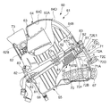
図2は、吸気装置60とその周辺を示す側面断面図である。
図2に示すように、エアクリーナケース61は、上下2分割で構成され、下面が開口した箱状の上部エアクリーナケース64と、上面が開口した箱状の下部エアクリーナケース65とを有している。エアクリーナケース61は、上部エアクリーナケース64と下部エアクリーナケース65とを、互いの開口を合わせる様に組み立てられて箱型に構成される。
上部エアクリーナケース64の前部には、コネクティングチューブ62が接続されるコネクティングチューブ用開口63が形成されている。下部エアクリーナケース65の後壁部65Aには、車両後方側に開口した吸気ダクト用開口66が形成され、この吸気ダクト用開口66には、外気をエアクリーナケース61に導入する吸気口としての吸気ダクト67が後方側に突出した状態で接続されている。吸気ダクト67は、チューブ状に形成され、下部エアクリーナケース65の後壁部65Aにおいて下部エアクリーナケース65の内外に突出した状態で設けられている。
FIG. 2 is a side sectional view showing the
As shown in FIG. 2, the
A connecting
上部エアクリーナケース64及び下部エアクリーナケース65の分割面61A、61Bは略平坦に形成され、この分割面61A、61Bには、板状に形成されたエレメントホルダ68が介装されている。エレメントホルダ68は、上部エアクリーナケース64の下面と下部エアクリーナケース65の上面とに狭持された状態で分割面61A、61Bの全体に亘って設けられている。
エレメントホルダ68は、その下面側、すなわち、組み付けられた状態において下部エアクリーナケース65の内部側に、エレメント保持部69を有し、このエレメント保持部69には、吸気ダクト67から吸い込まれた外気に含まれる塵埃等を吸着する板状エレメント70が保持されている。板状エレメント70は、その板形状の上下面にそれぞれ上側清浄化面70Aと下側清浄化面70Bとを有し、上側清浄化面70A及び下側清浄化面70Bは、板状エレメント70における最大面積を有する面となっている。板状エレメント70は、上側清浄化面70Aが上方向を指向して上部エアクリーナケース64の内部に面し、下側清浄化面70Bが下方向を指向して下部エアクリーナケース65の内部に面するように取り付けられる。
エレメントホルダ68は枠状に形成されており、吸気ダクト67から下部エアクリーナケース65内に導入された外気の全ては、下側清浄化面70Bから板状エレメント70内に入って浄化され、上側清浄化面70Aから上部エアクリーナケース64側に流入する。
The split surfaces 61A and 61B of the upper air
The
The
このように、エアクリーナケース61では、板状エレメント70によってダーティーサイドとクリーンサイドとが区画され、外気の取り入れ側であるダーティーサイドは下部エアクリーナケース65に対応し、清浄化された空気が通るクリーンサイドは上部エアクリーナケース64に対応している。
また、エレメントホルダ68は、後端側ほど板厚が薄くなるように形成されており、エレメント保持部69が形成された下面側が上面側に対して後ろ上がりに傾斜している。このため、板状エレメント70は、エレメントホルダ68の上面に対して後ろ上がりに傾斜した状態で保持される。
Thus, in the
Further, the
下部エアクリーナケース65の後壁部65Aには、板状エレメント70を下部エアクリーナケース65内に出し入れ可能にするメンテナンス用開口71が形成されている。メンテナンス用開口71の縁部には、後方側に突出した筒状の取付部71Aが形成されている。
メンテナンス用開口71は、後壁部65Aにおいて吸気ダクト用開口66の上方に設けられており、着脱自在なメンテナンスリッド72によって塞がれている。
メンテナンスリッド72は、メンテナンス用開口71を塞ぐ板状の蓋部72Aと、蓋部72Aからメンテナンスリッド72内に向かって立設されたリッド側ガイド部72Bと、メンテナンス用開口71の上部に引っ掛けられる引っ掛け部72Cと、下部エアクリーナケース65に締結されるリッド締結部72D(締結部)と、取付部71Aに嵌め込まれる溝部72Eとを有している。引っ掛け部72Cは蓋部72Aの上部に設けられ、リッド締結部72Dは引っ掛け部72Cと対向して蓋部72Aの下部に設けられている。
The
The
The
上部エアクリーナケース64は、その前端部において上部が後方側に一段窪んだ段部64Aを有し、コネクティングチューブ用開口63は段部64Aに形成されている。筒状のコネクティングチューブ62は、コネクティングチューブ用開口63を貫通して、上部エアクリーナケース64の下面と略平行に上部エアクリーナケース64の内外に突出するように配置され、その前部は段部64A内に収めて配置され、その後端62Aは、上部エアクリーナケース64内の前後の中間部まで延びている。
The upper air
また、コネクティングチューブ62の後端62Aは、上部エアクリーナケース64の後壁部64B(壁部)に対向して設けられ、後壁部64Bにおいて後端62Aと対向する部分及び後壁部64Bから上壁部64Cに連続する部分は、球状の曲面に形成された球状壁部64Dを有している。コネクティングチューブ62の後端62Aに対向する壁部は、エンジン12の吸気負圧が作用する部分であるが、本実施の形態では、この壁部を球状壁部64Dとして強度及び剛性を向上させたため、壁部の振動に起因する吸気音を低減させることができる。
The
エアクリーナケース61は、それ自身が前傾した状態で配置されている。詳細には、エアクリーナケース61は、コネクティングチューブ62、分割面61A、61B及び板状エレメント70が車両後方側に向けて後ろ上がりになる向きで配置されると共に、メンテナンスリッド72が車両後部の上方を向く向き、すなわち、メンテナンスリッド72がシート36の前部の裏面側に対向する向きとなるように配置されている。また、板状エレメント70は、シートレール20よりも大きい傾斜角度で後ろ上がりに傾斜している。
このように、本実施の形態では、板状エレメント70を後ろ上がりに傾斜(例えば、水平に対して45°以下の後ろ上がりに傾斜)して配置したため、板状エレメント70の大きさがエアクリーナケース61の高さ方向の大きさに大きく影響しない。これにより、エアクリーナケース61をエンジン12に近接させて配置でき、エンジン12の要求特性に応じてエアクリーナケース61を近接させて配置できるため、エンジン12の特性を向上できる。
また、前傾して配置されたエンジン12に対応させて、エアクリーナケース61も前傾させて配置したため、図1に示すように、コネクティングチューブ62及びスロットルボディ52をシリンダヘッド43の吸気口43Aに向かって前下がりに直線的に配置できる。これにより、吸気抵抗が低減されるため、吸気効率を向上できる。
The
As described above, in the present embodiment, the
Further, since the
エアクリーナケース61は、センターフレーム19の上方において下部エアクリーナケース65が左右のシートレール20の間に位置するように設けられ、その上部が、図1に示すように、側面視において燃料タンク35の後部の下部にオーバーラップして配置されている。詳細には、図2に示すように、前傾して組み付けられたエアクリーナケース61の上部は球状壁部64Dに相当し、燃料タンク35の下部には、球状壁部64Dを避けて上方に窪んだ曲面状凹部35Aが形成されている。
The
また、下部エアクリーナケース65の下部には、上部クロスメンバ27を逃げる凹部65Bが形成されている。
さらに、スロットルボディ52とエアクリーナケース61とに囲まれた部分において側面視で左右のメインフレーム17に重なる部分には、燃料タンク35から発生する蒸発燃料を吸着する筒状のキャニスタ59が配置されている。このように、キャニスタ59をメインフレーム17、スロットルボディ52及びエアクリーナケース61で囲まれる空間に配置したため、外観性に影響することなくキャニスタ59を設けることができる。
A
Further, a
図3は、吸気装置60とその周辺を示す側面図である。ここで、図3では、燃料タンク35及び左側のサイドカバー54等を外した状態を示している。図4は、吸気装置60の上部を前方側から見た正面図である。
図3及び図4に示すように、コネクティングチューブ用開口63は、段部64Aにおいて上部エアクリーナケース64の幅方向中央に設けられ、コネクティングチューブ62には、左側面側に開口したレゾネータ接続部62Bが設けられている。また、上部エアクリーナケース64の前部において、レゾネータ接続部62Bの反対側には、コネクティングチューブ62の右側面を覆う側壁部64Eが形成されている。
FIG. 3 is a side view showing the
As shown in FIGS. 3 and 4, the connecting
レゾネータ接続部62Bは水平よりも上方に傾斜して形成され、このレゾネータ接続部62Bにはレゾネータ73が接続されている。レゾネータ73は、エアクリーナケース61からコネクティングチューブ62を通ってスロットルボディ52へ流れる空気のチャンバであり、吸気音を低減する機能を有している。
レゾネータ73は、段部64A内に収まるように配置され、レゾネータ接続部62Bから車両左側に膨出した側室73Aと、コネクティングチューブ62の上方に回りこんで側壁部64Eの近傍まで車両右側へ延びた上室73Bとを有している。また、レゾネータ73は、側壁部64Eの上面に設けられたレゾネータ固定部64Fに締結固定されている。
The
The
車体が垂直に立てられた状態では、図4に示すように、レゾネータ73の上室73Bの底面73Cは略水平であり、側室73Aの底面73Dは、レゾネータ接続部62Bの傾斜に沿って車幅方向外側の上方に傾斜している。また、レゾネータ接続部62Bの内面における底部62Cと、側室73Aの底面73Dとは連続すると共に、略同一の傾斜角Aを有して形成されている。この傾斜角Aは、サイドスタンド39を使用して自動二輪車10を駐車する場合に車両が左側(図4においては右側)に傾斜する所定の角度よりも大きく形成されている。すなわち、サイドスタンド39を用いた駐車状態においても、レゾネータ接続部62B及び底面73Dはその外側部が上方に傾いた状態が維持されている。これにより、サイドスタンド39による駐車時に、レゾネータ73内に水滴等が発生したとしても、水滴等はレゾネータ接続部62B及び底面73Dに沿ってコネクティングチューブ62側に流れるため、水等がレゾネータ73内に貯留されることがない。
In the state where the vehicle body stands vertically, as shown in FIG. 4, the
図3に示すように、上部エアクリーナケース64の側面には、エアクリーナケース61を車体フレーム11に固定するためのケース側締結部75が形成されている。ケース側締結部75は、上部エアクリーナケース64の左右の各側面において、前部及び後部に1か所ずつ形成されており、計4箇所に設けられている。後部の各ケース側締結部75は、側面から下方に延びた脚部76の端に形成されている。また、各ケース側締結部75の座面は、シートレール20の上面に対して平行に形成されている。各ケース側締結部75は、上部エアクリーナケース64を樹脂成形する際に上部エアクリーナケース64と一体的に形成されている。このため、各ケース側締結部75は高い位置精度を有している。
As shown in FIG. 3, a case
また、ケース側締結部75に対応して車体フレーム11側に形成されたフレーム側締結部20Aは、左右の各シートレール20の上面の2箇所に設けられ、計4箇所に形成されている。そして、エアクリーナケース61を車体フレーム11に組付ける際には、エアクリーナケース61をシートレール20上に載置し、ケース側締結部75と各フレーム側締結部20Aとを、上方から締め込まれる4本のボルト77によって締結すれば良い。このように、シートレール20の上方からボルト77を締め付けることでエアクリーナケース61を取り付けできるため、組み付け作業が容易になり、生産性を向上できる。
Also, frame
図5は、メンテナンスリッド72の周辺を上方から見た平面図である。図6は、メンテナンスリッド72の周辺をメンテナンスリッド72と対向する後方位置から見た図である。ここで、図5及び図6では、シート36を取り外した状態を示している。
図2、図5及び図6に示すように、燃料タンク35には、後部から後方に突出した板状のステー固定部35Bが形成され、ステー固定部35Bは、シートレール20及びサイドカバー54の上方に位置している。このステー固定部35Bには、燃料タンク35をシートレール20に固定するタンク側ステー78(後方締結部)が溶接によって固定されている。
FIG. 5 is a plan view of the periphery of the
As shown in FIGS. 2, 5, and 6, the
タンク側ステー78は、図6に示すように、後面視で上方に突出したアーチ状に形成されており、燃料タンク35の後端に固定された板状の基部78Aと、基部78Aの左右端からそれぞれシートレール20の側に下方に延びた腕部78Bとを有している。タンク側ステー78はメンテナンスリッド72の上方に位置し、メンテナンスリッド72の上方を覆っている。
各腕部78Bの下端には、腕部78Bを幅方向外側に折り曲げて平らに形成した座部78Cが設けられている。左右の座部78Cは、各シートレール20の上方に突出したサイドカバー54の下方に潜り込むようにして各シートレール20の上面まで延びている。そして、燃料タンク35は、左右の座部78Cにそれぞれ挿通されるタンク固定ボルト79によってシートレール20に固定される。
As shown in FIG. 6, the tank side stay 78 is formed in an arch shape protruding upward in the rear view, and has a plate-
At the lower end of each
左右の各シートレール20の上面には、板状のフレーム側ステー20Bが設けられている。図6に示すように、燃料タンク35は、左右のフレーム側ステー20Bと座部78Cの下面との間、及び、タンク固定ボルト79と座部78Cの上面との間にラバー80を介装された状態でタンク左右のタンク固定ボルト79が締め込まれることで、シートレール20にラバーマウントされる。このため、左右のシートレール20と燃料タンク35との間の振動をラバー80によって低減することができる。
Plate-like frame side stays 20 </ b> B are provided on the upper surfaces of the left and right seat rails 20. As shown in FIG. 6, the
本実施の形態では、燃料タンク35を、燃料タンク35の後部に設けたアーチ状のタンク側ステー78を用いて固定することで、燃料タンク35の後方において、タンク側ステー78及びタンク側ステー78と連続して後方に延びるシート36の下方に空間Kを確保している。この空間Kは、メンテナンス用開口71及びメンテナンスリッド72に臨んで設けられており、板状エレメント70を着脱する際に、メンテナンス用開口71から、板状エレメント70を、メンテナンスリッド72の蓋部72Aの面の法線に沿うようにして、上後方に引き出し或いは下前方に押し込み可能な大きさになっている。
In the present embodiment, the
図2に示すように、メンテナンスリッド72の蓋部72Aはシート36の裏面側に対向する角度に傾斜して配置されている。図5及び図6に示すように、蓋部72Aの幅は左右のシートレール20間の幅よりも小さく形成され、蓋部72Aは、左右のシートレール20の間に配置されている。また、リッド締結部72Dは、蓋部72Aの下部において幅方向の両端にそれぞれ設けられている。このリッド締結部72Dはねじ式の締結部であり、蓋部72Aの面に略垂直に立設されている。
図6に示すように、リッド側ガイド部72B及び引っ掛け部72Cは、蓋部72Aの裏面側に設けられ、リッド側ガイド部72Bは、蓋部72Aの幅方向中央に位置し、引っ掛け部72Cは蓋部72Aの幅方向の両端側の2箇所に位置している。
As shown in FIG. 2, the
As shown in FIG. 6, the lid-
メンテナンスリッド72の後方には、シート下クロスメンバ26が設けられており、リッド締結部72Dとシート下クロスメンバ26とは、所定の位置関係を有して配置されている。詳細には、図2に示すように、リッド締結部72Dは、リッド締結部72Dの軸線Tがシート下クロスメンバ26の上方を通り、軸線Tがシート下クロスメンバ26に緩衝しない位置関係で配置されている。すなわち、図6に示すように、蓋部72Aに対向する後方側からメンテナンスリッド72を見た場合、シート下クロスメンバ26とリッド締結部72Dとは重ならず、シート下クロスメンバ26が邪魔にならないため、リッド締結部72Dを軸線Tの方向に引き出して簡単に取り外すことができる。
The under-
さらに、メンテナンス用開口71は軸線Tよりも上方に位置しており、メンテナンス用開口71から板状エレメント70を着脱する場合においても、シート下クロスメンバ26に板状エレメント70が当たらないため、板状エレメント70を空間Kを介して簡単に着脱できる。また、空間K内には、メンテナンス用開口71から板状エレメント70を蓋部72Aの法線方向に移動させた場合に板状エレメント70と重なる部品が配置されていない。
このように、本構成では、タンク側ステー78及びシート36の下方に空間Kが確保されていると共に、シート下クロスメンバ26がリッド締結部72D及び板状エレメント70を着脱する際の邪魔にならないため、簡単に板状エレメント70のメンテナンスを行うことができる。また、空間Kはシート36の下方に位置する空間であり、空間Kには他の部品が配置されていないため、他の部品を設けない分だけシート36の高さを低く設定することができる。
また、バッテリー9は、シート下クロスメンバ26の後方において、空間Kの外側に配置されている。
Further, the
Thus, in this configuration, the space K is secured below the tank side stay 78 and the
Further, the
以下、吸気装置60の細部構成について説明する。
図7は、吸気装置60の一部断面側面図である。図8は、下部エアクリーナケース65の平面図である。ここで、図8では、下部エアクリーナケース65と共に、エレメントホルダ68を2点鎖線で示している。
図8に示すように、下部エアクリーナケース65は平面視で略矩形に形成され、後部ほど幅狭に形成されている。また、2点鎖線で示すように、エレメントホルダ68は平面視において下部エアクリーナケース65と略同一形状に形成され、下部エアクリーナケース65の上部に取り付けられている。
Hereinafter, a detailed configuration of the
FIG. 7 is a partial cross-sectional side view of the
As shown in FIG. 8, the lower
図7及び図8に示すように、下部エアクリーナケース65の上部には、下部エアクリーナケース65の外周側の壁部から外側に突出した下部ケース固定部81が複数形成されている。また、上部エアクリーナケース64の下部における外周側の壁部には、下部ケース固定部81に対応した位置に上部ケース固定部82が複数形成されている。
エアクリーナケース61は、下部エアクリーナケース65と上部エアクリーナケース64との間にエレメントホルダ68を狭持した状態で、下部ケース固定部81と上部ケース固定部82とを締結するねじ83を締め込むことで組み立てられる。
As shown in FIGS. 7 and 8, a plurality of lower
The
図2及び図7に示すように、エレメントホルダ68の下面の外縁部には、下方に向けて立設された下面凸部84が設けられている。また、エレメントホルダ68の上面の外縁部にも、上方に向けて立設された上面凸部85が形成されている。下面凸部84及び上面凸部85は、エレメントホルダ68の外縁部の全周に亘って形成されている。
下部エアクリーナケース65の上縁部には、エレメントホルダ68の下面凸部84が係合する係合溝86Aが形成されている。また、上部エアクリーナケース64の下縁部には、エレメントホルダ68の上面凸部85が係合する係合溝86Bが形成されている。
このように、エレメントホルダ68を、下面凸部84及び上面凸部85を係合溝86A、86Bにそれぞれ係合させて組み立てるため、エレメントホルダ68を確実に位置決めできると共に、エアクリーナケース61の密閉性を向上できる。
As shown in FIG. 2 and FIG. 7, a lower surface
An engaging groove 86 </ b> A for engaging with the lower surface
Thus, the
図9は、板状エレメント70及びエレメントホルダ68の側面図である。図10は、板状エレメント70及びエレメントホルダ68を車両後方側から見た図である。
図2、図9及び図10に示すように、板状エレメント70は、板状エレメント70の上部に設けられた板状の枠部87と、枠部87から下方に膨出するように設けられた板状のエレメント本体部88とを有している。
FIG. 9 is a side view of the
As shown in FIGS. 2, 9, and 10, the plate-
枠部87の前端には、前方に突出した前部突起87Aが形成されている。前部突起87Aは、板状エレメント70の幅方向の2箇所に設けられている。
また、枠部87の後端には、枠部87の後端を下方に屈曲して形成された板状の可撓部87Bが設けられ、この可撓部87Bの後面には、後方へ突出した後部突起87Cが形成されている。可撓部87Bは、後方から押圧等によって前方側への力を受けた場合、前方側に撓むことができる。図10に示すように、可撓部87B及び後部突起87Cは、板状エレメント70の幅方向の2箇所に設けられている。
また、図9及び図10に示すように、枠部87の幅方向の両側面には、外側に突出したガイドレール87Dがそれぞれ形成されている。ガイドレール87Dは、枠部87の前後方向に連続してレール状に設けられている。
A
In addition, a plate-like
Further, as shown in FIGS. 9 and 10,
エレメントホルダ68は、その下面側に上記エレメント保持部69を有し、エレメント保持部69は、エレメントホルダ68の前端から下方に突出した前係合部89と、エレメントホルダ68の後端から下方に突出した後係合部90とを備えている。
エレメントホルダ68の前係合部89には、板状エレメント70の前部突起87Aが係合する前孔部89Aが形成されており、後係合部90には、板状エレメント70の後部突起87Cが係合する後孔部90Aが形成されている。図10に示すように、前係合部89及び後係合部90は、エレメントホルダ68の幅方向の2箇所にそれぞれ設けられている。
The
The
エレメントホルダ68は、前部突起87Aと後係合部90との間の前後方向の中間部に、下方に突出したエレメントガイド部91を有している。エレメントガイド部91は、板状エレメント70が固定される位置よりも下方側に形成されており、板状エレメント70の着脱の際に板状エレメント70を保持する機能を有している。
エレメントガイド部91は、図10に示すように、幅方向に左右一対で設けられ、エレメントホルダ68の左右の端部から下方に延びる延出部91Aと、各延出部91Aの下端が幅方向内側に屈曲されて形成されたガイド部91Bとを有している。このガイド部91Bは、後ろ上がりに傾斜した状態で前後に延在しており、図2に示すように、その傾斜角度は、板状エレメント70の傾斜角度よりも小さく設定されている。
The
As shown in FIG. 10, the
エレメントホルダ68のガイド部91Bは、板状エレメント70のガイドレール87Dを受ける部分である。すなわち、左右のエレメントガイド部91の間を通るようにセットされた板状エレメント70は、ガイドレール87Dの下面87Eがガイド部91Bの上面91C上を滑りながらエレメントホルダ68に押し込まれる。
エレメントホルダ68に押し込まれた板状エレメント70は、前部突起87Aがエレメントホルダ68の前係合部89の前孔部89Aに係合され、その後、メンテナンスリッド72のリッド側ガイド部72Bによって固定位置まで押し上げられて、可撓部87Bの後部突起87Cが後係合部90の後孔部90Aに係合することで固定される。詳細には、板状エレメント70は、前部突起87Aが前係合部89の前孔部89Aに係合した状態で、リッド側ガイド部72Bによって押し上げられ、前孔部89Aを中心として上方に回動して固定位置に達する。この固定位置では、板状エレメント70は、リッド側ガイド部72Bの先端72Fによって前係合部89に押し付けられると共に、リッド側ガイド部72Bの上面部72Gによってエレメントホルダ68の下面に押し付けられている。これにより、板状エレメント70をエレメントホルダ68に密着させることができ、ダーティーサイドとクリーンサイドとの間を確実に密閉できる。
The
The plate-
図7に示すように、メンテナンスリッド72は、上部の溝部72E1がメンテナンス用開口71の取付部71Aの上部71Bに引っ掛けられた状態で、溝部72E1を中心にメンテナンスリッド72を回動させるようにして取り付けられる。このため、取り付けの際には、リッド側ガイド部72Bの先端は、図7中に軌跡Xで示すように、円弧状の軌跡を描くように上方へ移動する。
As shown in FIG. 7, the
エレメントガイド部91によってガイドされてエレメントホルダ68に押し込まれた状態における板状エレメント70の可撓部87Bの位置は、図7中に二点鎖線で示すように、軌跡Xよりも内側に位置し、リッド側ガイド部72Bの回動範囲に重なっている。すなわち、板状エレメント70は、メンテナンスリッド72が取り付けられる際にリッド側ガイド部72Bによって押し上げられることで、固定位置にセットされる。これにより、メンテナンスリッド72の取り付けと同時に板状エレメント70を固定することができる。
また、可撓部87Bはリッド側ガイド部72Bによって押し上げられた際に、後部突起87Cが後係合部90に当接することで前側に撓み、板状エレメント70がさらに押し上げられることによって後部突起87Cが後孔部90Aに係合すると元の状態に戻る。
また、メンテナンスリッド72の上部は、引っ掛け部72Cが吸気ダクト用開口66の上部の内壁66Bに引っ掛かることで固定されるため、ねじ等を使用する締結部を削減できる。
The position of the
Further, when the
Further, since the upper portion of the
ここで、図2、図7、図9及び図10を参照して、板状エレメント70の着脱の手順を説明する。
板状エレメント70を取り付ける場合、まず、上述したシート36のロック機構を解除してシート36を取外し、メンテナンスリッド72を空間Kを介して外側に露出させる。次いで、空間Kに手を入れてリッド締結部72Dの締結を解除し、リッド締結部72D及びメンテナンスリッド72を取り外す。次に、メンテナンス用開口71から板状エレメント70を挿入し、板状エレメント70をエレメントホルダ68にセットする。この際、板状エレメント70は、ガイドレール87Dがガイド部91Bによって位置を規制されるため、図9に示す矢印の方向に真直ぐにガイドされ、前部突起87Aが確実に前孔部89Aに係合する。このため、板状エレメント70を確実に、かつ、簡単に正しい位置へセットすることができる。
そして、メンテナンスリッド72をメンテナンス用開口71に取り付けることで、板状エレメント70はリッド側ガイド部72Bによって固定位置に押し上げられ、後部突起87Cが後孔部90Aと係合することで完全に固定される。その後、リッド締結部72Dを締結し、シート36を取り付ければ良い。
Here, a procedure for attaching and detaching the
When the plate-
Then, by attaching the
また、板状エレメント70を取り外す場合、まず、取り付けの場合と同様の手順によって、メンテナンスリッド72を取り外す。次いで、メンテナンス用開口71の内部に位置する可撓部87Bを押圧し、後部突起87Cと後孔部90Aとの係合を解除する。後部突起87Cと後孔部90Aとの係合を解除すると、板状エレメント70は自重により落下し、エレメントガイド部91によって保持される位置まで落下する。その後、メンテナンス用開口71から空間Kを介して板状エレメント70を引き出すことで、板状エレメント70を取り外すことができる。この際、板状エレメント70は、ガイドレール87Dがガイド部91Bによってガイドされて空間K側に案内されるため、スムーズに板状エレメント70を引き出すことができる。
When removing the plate-
本実施の形態では、メンテナンス用開口71及びメンテナンスリッド72がシート36の前部に対向した状態で設けられると共に、メンテナンスリッド72とシート36との間に空間Kが設けられているため、シート36が取り外された状態とすることで、空間Kを介してメンテナンスリッド72及び板状エレメント72を着脱してメンテナンスを容易にすることができる。ここで、メンテナンスリッド72がシート36に対向する状態とは、蓋部72Aの面の法線が側面視において少なくともシート36の一部にオーバーラップした状態を指し、蓋部72Aの面の法線に沿って空間Kを介して板状エレメント72を着脱できれば良く、メンテナンスリッド72はシート36に対して完全に対向している必要はない。
In the present embodiment, the
以上説明したように、本発明を適用した実施の形態によれば、板状エレメント70を後ろ上がりに傾斜して配置することで、板状エレメント70の大きさがエアクリーナケース61の高さ方向の大きさに影響しないため、エアクリーナケース61を高さ方向にコンパクトに配置できる。これにより、エアクリーナケース61をエンジン12の要求特性に応じてエンジン12に近接させて配置できるとともに、エアクリーナケース61の上方のシート36の高さを低減できる。また、メンテナンスリッド72が燃料タンク35の後方のシート36に対向して設けられたため、エアクリーナケース61をエンジン12に近接させて配置した場合においても燃料タンク35が邪魔になることが無く、燃料タンク35をずらしたり、取り外したりすることなく、シート36の側から板状エレメント70を着脱してメンテナンスをすることができ、メンテナンス性を向上できる。さらに、シート36の下方はメンテナンスリッド72が臨む空間Kが形成されるだけであるため、シート36の高さを低減させて自動二輪車10の取り廻し性を向上できる。
また、シート36が取り付けられた状態では、メンテナンスリッド72がシート36の下に位置しており、外側から視認されないため、外観性を向上できる。
As described above, according to the embodiment to which the present invention is applied, by arranging the
Further, when the
また、上下2分割で構成されたエアクリーナケース61の下部エアクリーナケース65に板状エレメント70を配置したため、板状エレメント70の着脱の際に、板状エレメント70に付着した塵埃が、上部エアクリーナケース64の側、すなわち、クリーンサイド側に落ちることを防止でき、メンテナンス性を向上できる。また、下部エアクリーナケース65の側、すなわち、外気が導入されるダーティーサイド側にメンテナンスリッド72を配置したため、メンテナンスリッド72と下部エアクリーナケース65との間の気密性の管理が比較的容易になり、生産性を向上できる。
Further, since the plate-
また、板状エレメント70をメンテナンスリッド72から、挿入或いは引き出しする際に、エレメントホルダ68のエレメントガイド部91を利用して、板状エレメント70を正しい位置に案内できるため、板状エレメント70の着脱性を向上できる。
さらに、メンテナンスリッド72をメンテナンス用開口71に固定すると、リッド側ガイド部72Bによって板状エレメント70が押し上げられて板状エレメント70も同時に固定されるため、メンテナンス性を向上できる。また、メンテナンスリッド72を取り外すと、板状エレメント70が、エレメントガイド部91によって保持される位置まで自重によって下がることが可能なため、板状エレメント70が抜き易くなる。
Further, when the
Furthermore, when the
さらにまた、メンテナンスリッド72の上部に引っ掛け部72Cを設け、メンテナンスリッド72の上部を締結等により固定しないため、メンテナンスリッド72の上部の溝部72E1を支点にしてメンテナンスリッド72を回動させながらメンテナンス用開口71に取り付けできるため、リッド側ガイド部72Bで板状エレメント70を持ち上げることができ、板状エレメント70を固定位置まで押し上げることができる。また、メンテナンスリッド72の上部に引っ掛け部72Cを設けたため、上部に締結部品を設ける必要が無く、締結部品の点数を削減して生産性の向上及び軽量化を図ることができる。
Furthermore, a
また、エアクリーナケース61のシートレール20への全ての締結部をケース側締結部75とし、ケース側締結部75を上部エアクリーナケース64に一体的に形成するため、各ケース側締結部75の位置精度を向上させることができ、生産性が向上する。また、シートレール20の上方側からケース側締結部75を締め付けてエアクリーナケース61を組み付けできるため、組み付け作業が容易になり、さらに生産性が向上する。
Moreover, since all the fastening parts to the
また、エンジン12の吸気負圧が作用する上部エアクリーナケース64の壁部を球状壁部64Dとして、壁部の剛性を増加させたため、壁部の振動に起因する吸気音を低減できる。
さらに、燃料タンク35の後部のステー固定部35Bにアーチ状のタンク側ステー78を備えたため、燃料タンク35の後方に、メンテナンスリッド72及び板状エレメント70が通過可能な空間Kを確保できる。また、タンク側ステー78は、左右一対のシートレール20を連結する部材としても機能するため、シートレール20の強度及び剛性を向上できる。
In addition, since the wall portion of the upper air
Furthermore, since the arch-shaped tank side stay 78 is provided in the
なお、上記実施の形態は本発明を適用した一態様を示すものであって、本発明は上記実施の形態に限定されない。
上記実施の形態では、エアクリーナケース61は上下2分割で構成され、上部エアクリーナケース64と下部エアクリーナケース65とを有するものとして説明したが、本発明はこれに限定されるものではなく、例えば、一体的に構成されたエアクリーナケース内に板状エレメント70を設け、板状エレメント70が後ろ上がりに傾斜するようにエアクリーナケースを配置し、エアクリーナケースの後部に設けたメンテナンスリッドをシート36に対向させて設けても良い。また、その他の自動二輪車10の細部構成についても任意に変更可能であることは勿論である。
In addition, the said embodiment shows the one aspect | mode which applied this invention, Comprising: This invention is not limited to the said embodiment.
In the above embodiment, the
10 自動二輪車
11 車体フレーム
12 エンジン(内燃機関)
20 シートレール(フレーム部材)
20A フレーム側締結部
35 燃料タンク
36 シート
61 エアクリーナケース
61A、61B 分割面
62 コネクティングチューブ
63 コネクティングチューブ用開口
64 上部エアクリーナケース
64B 後壁部(壁部)
65 下部エアクリーナケース
66 吸気ダクト用開口
68 エレメントホルダ
70 板状エレメント
70A 上側清浄化面(清浄化面)
70B 下側清浄化面(清浄化面)
72 メンテナンスリッド
72B リッド側ガイド部
72C 引っ掛け部
72D リッド締結部(締結部)
75 ケース側締結部
78 タンク側ステー(後方締結部)
91 エレメントガイド部
WF 前輪
WR 後輪
10
20 Seat rail (frame member)
20A Frame
65 Lower air
70B Lower cleaning surface (cleaning surface)
72
75 Case
91 Element guide part WF Front wheel WR Rear wheel
Claims (5)
前記内燃機関(12)はシリンダの軸が前傾して設けられる4サイクルエンジンであり、
前記エアクリーナケース(61)がシリンダの上部に設けられるシリンダヘッド(43)の後方で前記燃料タンク(35)下方に配置されると共に、上下2分割で構成され、上部エアクリーナケース(64)がクリーンサイドに、下部エアクリーナケース(65)がダーティーサイドに形成され、前記エアクリーナケース(61)の吸気ダクト(67)は前記メンテナンスリッド(72)の下方に設けられ、
前記上部エアクリーナケース(64)に、前記内燃機関(12)へ吸気を供給するコネクティングチューブ用開口(63)が形成され、前記下部エアクリーナケース(65)に、外気を前記エアクリーナケース(61)に導入する吸気ダクト用開口(66)が形成され、前記板状エレメント(70)及び前記メンテナンスリッド(72)が前記下部エアクリーナケース(65)に配置され、
前記上部エアクリーナケース(64)と前記下部エアクリーナケース(65)との分割面にエレメントホルダ(68)を狭持し、
前記エレメントホルダ(68)の下部に前記板状エレメント(70)を保持するエレメントガイド部(91)を形成し、車両側面視で、前記板状エレメント(70)がその清浄化面を上下方向を指向して後ろ上がりに傾斜して配置され、
前記シート(36)の前端の下方には、前記シート(36)を支持する左右のシートレール(20)の間に、他の部品が配置されない空間(K)が形成されており、
前記メンテナンスリッド(72)が、空間(K)に臨んで設けられるとともに、前記シート(36)を取り外して前記板状エレメント(70)を引き出し可能に前記シート(36)の下方で前記シート(36)に対向して設けられ、
前記エレメントガイド部(91)は、前記板状エレメント(70)の下方で、前記板状エレメント(70)の傾斜角度よりも小さい角度で後上がりに形成されるとともに、前記板状エレメント(70)を押し込み方向及び空間(K)側への引き出し方向にガイドするガイド部(91B)を備え、
前記メンテナンスリッド(72)に前記エアクリーナケース(61)の内側に突出するリッド側ガイド部(72B)が形成され、当該リッド側ガイド部(72B)は、前記メンテナンスリッド(72)が前記エアクリーナケース(61)に固定された状態で、前記板状エレメント(70)を固定位置まで押し上げるように形成され、
前記エレメントガイド部(91)は、前記リッド側ガイド部(72B)の押し上げが解除されて前記板状エレメント(70)を取り外す際に自重で落下する前記板状エレメント(70)を保持すること、を特徴とする自動二輪車。 A vehicle body frame (11) for holding the front wheel (WF) in a steerable manner and a rear wheel (WR) in a swingable manner, and a fuel tank (35) disposed above the front portion of the vehicle body frame (11) And a seat (36) disposed behind the fuel tank (35) and above the vehicle body frame (11), and suspended below the fuel tank (35) and below the vehicle body frame (11). An internal combustion engine (12), an air cleaner case (61) for cleaning the taken-in outside air and supplying the air to the internal combustion engine (12), a plate-like element (70) disposed in the air cleaner case (61), In a motorcycle comprising a part of an air cleaner case (61) and a maintenance lid (72) used when the plate element (70) is attached or detached,
The internal combustion engine (12) is a four-cycle engine provided with a cylinder axis inclined forward.
The air cleaner case (61) is disposed below the fuel tank (35) behind a cylinder head (43) provided at the upper part of the cylinder, and is divided into upper and lower parts, and the upper air cleaner case (64) is a clean side. Further, a lower air cleaner case (65) is formed on the dirty side, and an air intake duct (67) of the air cleaner case (61) is provided below the maintenance lid (72),
The upper air cleaner case (64) is formed with a connecting tube opening (63) for supplying intake air to the internal combustion engine (12), and external air is introduced into the lower air cleaner case (65) into the air cleaner case (61). An intake duct opening (66) is formed, and the plate element (70) and the maintenance lid (72) are disposed in the lower air cleaner case (65),
An element holder (68) is sandwiched between split surfaces of the upper air cleaner case (64) and the lower air cleaner case (65),
An element guide portion (91) for holding the plate-like element (70) is formed at the lower part of the element holder (68) , and the plate-like element (70) has its cleaning surface up and down in the vehicle side view. Oriented and tilted backwards upward,
Below the front end of the seat (36), a space (K) in which no other parts are arranged is formed between the left and right seat rails (20) that support the seat (36).
The maintenance lid (72) is provided facing the space (K), and the sheet (36) can be pulled out and the plate-like element (70) can be pulled out. ) opposite provided,
The element guide portion (91) is formed rearwardly at an angle smaller than the inclination angle of the plate-like element (70) below the plate-like element (70), and the plate-like element (70). Including a guide portion (91B) for guiding in a pushing direction and a drawing direction toward the space (K) side,
The maintenance lid (72) is formed with a lid-side guide portion (72B) projecting inward of the air cleaner case (61). The lid-side guide portion (72B) is connected to the air cleaner case (72). 61) in a state of being fixed to the plate-shaped element (70) to be pushed up to a fixed position,
The element guide portion (91) holds the plate-like element (70) that falls by its own weight when the lid-side guide portion (72B) is released from being lifted and the plate-like element (70) is removed , Motorcycle characterized by
前記燃料タンク(35)は、後部に後面視でアーチ状に形成された後方締結部(78)を備え、該後方締結部(78)の車幅方向両端部を介して左右一対の前記フレーム部材(20)に固定されたこと、を特徴とする請求項1から4のいずれかに記載の自動二輪車。 The vehicle body frame (11) is composed of at least a pair of left and right frame members (20),
The fuel tank (35) includes a rear fastening portion (78) formed in an arch shape in a rear view at a rear portion, and a pair of left and right frame members via both ends in the vehicle width direction of the rear fastening portion (78). The motorcycle according to any one of claims 1 to 4 , wherein the motorcycle is fixed to (20).
Priority Applications (9)
| Application Number | Priority Date | Filing Date | Title |
|---|---|---|---|
| JP2009194735A JP5399168B2 (en) | 2009-08-25 | 2009-08-25 | Motorcycle |
| BR112012004234-3A BR112012004234B1 (en) | 2009-08-25 | 2010-07-05 | MOTOR VEHICLE WITH TWO WHEELS |
| PCT/JP2010/004373 WO2011024368A1 (en) | 2009-08-25 | 2010-07-05 | Two-wheeled motor vehicle |
| CN201080033489.2A CN102597482B (en) | 2009-08-25 | 2010-07-05 | Motor bike |
| EP10811427.3A EP2472094B1 (en) | 2009-08-25 | 2010-07-05 | Two-wheeled motor vehicle |
| US13/389,729 US8302722B2 (en) | 2009-08-25 | 2010-07-05 | Two-wheeled motor vehicle |
| AU2010288005A AU2010288005B2 (en) | 2009-08-25 | 2010-07-05 | Two-wheeled motor vehicle |
| ZA2012/01068A ZA201201068B (en) | 2009-08-25 | 2012-02-14 | Two-wheeled motor vehicle |
| CO12027731A CO6430488A2 (en) | 2009-08-25 | 2012-02-16 | MOTORCYCLE |
Applications Claiming Priority (1)
| Application Number | Priority Date | Filing Date | Title |
|---|---|---|---|
| JP2009194735A JP5399168B2 (en) | 2009-08-25 | 2009-08-25 | Motorcycle |
Publications (3)
| Publication Number | Publication Date |
|---|---|
| JP2011047294A JP2011047294A (en) | 2011-03-10 |
| JP2011047294A5 JP2011047294A5 (en) | 2012-10-04 |
| JP5399168B2 true JP5399168B2 (en) | 2014-01-29 |
Family
ID=43627491
Family Applications (1)
| Application Number | Title | Priority Date | Filing Date |
|---|---|---|---|
| JP2009194735A Expired - Fee Related JP5399168B2 (en) | 2009-08-25 | 2009-08-25 | Motorcycle |
Country Status (9)
| Country | Link |
|---|---|
| US (1) | US8302722B2 (en) |
| EP (1) | EP2472094B1 (en) |
| JP (1) | JP5399168B2 (en) |
| CN (1) | CN102597482B (en) |
| AU (1) | AU2010288005B2 (en) |
| BR (1) | BR112012004234B1 (en) |
| CO (1) | CO6430488A2 (en) |
| WO (1) | WO2011024368A1 (en) |
| ZA (1) | ZA201201068B (en) |
Families Citing this family (23)
| Publication number | Priority date | Publication date | Assignee | Title |
|---|---|---|---|---|
| JP5624780B2 (en) * | 2010-03-23 | 2014-11-12 | 本田技研工業株式会社 | Air cleaner device |
| CN102996296B (en) * | 2011-09-16 | 2015-07-01 | 雅马哈发动机株式会社 | Motorcycle |
| JP5912589B2 (en) * | 2012-01-31 | 2016-04-27 | 本田技研工業株式会社 | Air cleaner device for vehicle |
| JP5928042B2 (en) * | 2012-03-21 | 2016-06-01 | スズキ株式会社 | Air cleaner for motorcycle |
| JP5893459B2 (en) * | 2012-03-22 | 2016-03-23 | 本田技研工業株式会社 | Fuel tank and radiator arrangement structure for saddle-ride type vehicles |
| CN104321244B (en) * | 2012-05-28 | 2017-03-08 | 本田技研工业株式会社 | Straddle-type vehicle |
| JP5961492B2 (en) * | 2012-08-31 | 2016-08-02 | 本田技研工業株式会社 | Rear structure of saddle riding type vehicle |
| JP6083601B2 (en) * | 2013-03-29 | 2017-02-22 | 本田技研工業株式会社 | Air cleaner structure in saddle riding type vehicle |
| DE102013215607A1 (en) | 2013-08-07 | 2015-03-05 | Mahle International Gmbh | Fresh air system |
| JP5852071B2 (en) * | 2013-09-26 | 2016-02-03 | 本田技研工業株式会社 | Air intake structure for saddle-ride type vehicles |
| JP5950214B2 (en) * | 2014-01-15 | 2016-07-13 | 本田技研工業株式会社 | Air cleaner for saddle-ride type vehicle engine |
| DE102014207167A1 (en) | 2014-04-15 | 2015-10-15 | Bayerische Motoren Werke Aktiengesellschaft | Intake device with formally integrated Luftführungsansaugkanal |
| JP6140753B2 (en) * | 2015-03-31 | 2017-05-31 | 本田技研工業株式会社 | Saddle riding vehicle |
| US10160509B2 (en) * | 2015-03-31 | 2018-12-25 | Honda Motor Co., Ltd. | Motorcycle |
| JP2017105286A (en) * | 2015-12-08 | 2017-06-15 | スズキ株式会社 | Saddle-riding type vehicle |
| JP6629656B2 (en) | 2016-03-30 | 2020-01-15 | 本田技研工業株式会社 | Saddle-type vehicle |
| JP6364446B2 (en) * | 2016-06-30 | 2018-07-25 | 本田技研工業株式会社 | Motorcycle |
| JP6456991B2 (en) * | 2017-02-27 | 2019-01-23 | 本田技研工業株式会社 | Intake structure of air cleaner for automobile |
| DE102018003414A1 (en) | 2017-04-28 | 2018-10-31 | Mann+Hummel Gmbh | Filter device, in particular air filter, and method for maintaining a filter device and its use |
| KR102347737B1 (en) * | 2017-12-15 | 2022-01-06 | 현대자동차주식회사 | Air cleaner assembly of vehicle having support members |
| CN109650294B (en) * | 2019-01-11 | 2023-09-12 | 北京君合嘉成科技有限公司 | Fork mechanism |
| JP6812472B2 (en) * | 2019-01-30 | 2021-01-13 | 本田技研工業株式会社 | Intake device structure for saddle-riding vehicles |
| JP7344947B2 (en) * | 2021-09-30 | 2023-09-14 | 本田技研工業株式会社 | Air cleaner structure for saddle type vehicles |
Family Cites Families (16)
| Publication number | Priority date | Publication date | Assignee | Title |
|---|---|---|---|---|
| JPS55164765A (en) * | 1979-06-08 | 1980-12-22 | Yamaha Motor Co Ltd | Air cleaner device |
| JPS60101268A (en) * | 1983-11-05 | 1985-06-05 | Yamaha Motor Co Ltd | Air cleaner element fixing structure |
| JP2581926B2 (en) * | 1987-08-22 | 1997-02-19 | 本田技研工業株式会社 | Air cleaner for internal combustion engine |
| JPH01208559A (en) * | 1988-02-12 | 1989-08-22 | Suzuki Motor Co Ltd | Air cleaner device for engine of motorcycle |
| JP3109124B2 (en) * | 1991-04-26 | 2000-11-13 | スズキ株式会社 | Motorcycle air cleaner device |
| JP3251953B2 (en) * | 1991-07-17 | 2002-01-28 | 本田技研工業株式会社 | Air cleaner for motorcycles and tricycles |
| SE9304305L (en) * | 1992-12-30 | 1994-07-01 | Hyundai Motor Co Ltd | Air cleaner device for vehicles |
| JP3175442B2 (en) * | 1993-11-11 | 2001-06-11 | スズキ株式会社 | Motorcycle air cleaner |
| JP3466043B2 (en) | 1997-03-21 | 2003-11-10 | 本田技研工業株式会社 | Air cleaner device for vehicle engine |
| GB2348153A (en) * | 1999-03-25 | 2000-09-27 | Draftex Ind Ltd | Easily removable air filter for internal combustion engine air intake. |
| JP2001329921A (en) * | 2000-03-17 | 2001-11-30 | Toyo Roki Mfg Co Ltd | Air cleaner |
| JP2001280208A (en) * | 2000-03-31 | 2001-10-10 | Honda Motor Co Ltd | Air cleaner mounting structure for motorcycle |
| JP4079689B2 (en) * | 2002-05-17 | 2008-04-23 | 和興フィルタテクノロジー株式会社 | Air cleaner and its filter element |
| JP2006088895A (en) * | 2004-09-24 | 2006-04-06 | Yamaha Motor Co Ltd | Saddle riding type vehicle |
| US8157041B2 (en) * | 2007-03-22 | 2012-04-17 | Suzuki Kabushiki Kaisha | Intake device for motorcycle |
| JP5142781B2 (en) * | 2008-03-27 | 2013-02-13 | 本田技研工業株式会社 | Motorcycle |
-
2009
- 2009-08-25 JP JP2009194735A patent/JP5399168B2/en not_active Expired - Fee Related
-
2010
- 2010-07-05 US US13/389,729 patent/US8302722B2/en not_active Expired - Fee Related
- 2010-07-05 WO PCT/JP2010/004373 patent/WO2011024368A1/en active Application Filing
- 2010-07-05 EP EP10811427.3A patent/EP2472094B1/en not_active Not-in-force
- 2010-07-05 AU AU2010288005A patent/AU2010288005B2/en not_active Ceased
- 2010-07-05 BR BR112012004234-3A patent/BR112012004234B1/en active IP Right Grant
- 2010-07-05 CN CN201080033489.2A patent/CN102597482B/en active Active
-
2012
- 2012-02-14 ZA ZA2012/01068A patent/ZA201201068B/en unknown
- 2012-02-16 CO CO12027731A patent/CO6430488A2/en active IP Right Grant
Also Published As
| Publication number | Publication date |
|---|---|
| CO6430488A2 (en) | 2012-04-30 |
| CN102597482A (en) | 2012-07-18 |
| BR112012004234B1 (en) | 2020-09-29 |
| EP2472094A1 (en) | 2012-07-04 |
| AU2010288005B2 (en) | 2014-05-08 |
| BR112012004234A2 (en) | 2016-04-05 |
| CN102597482B (en) | 2015-09-30 |
| EP2472094B1 (en) | 2015-01-28 |
| WO2011024368A1 (en) | 2011-03-03 |
| EP2472094A4 (en) | 2013-04-10 |
| JP2011047294A (en) | 2011-03-10 |
| US20120145470A1 (en) | 2012-06-14 |
| US8302722B2 (en) | 2012-11-06 |
| AU2010288005A1 (en) | 2012-02-23 |
| ZA201201068B (en) | 2013-05-29 |
Similar Documents
| Publication | Publication Date | Title |
|---|---|---|
| JP5399168B2 (en) | Motorcycle | |
| JP5624780B2 (en) | Air cleaner device | |
| JP5301374B2 (en) | Motorcycle | |
| US7549675B2 (en) | Straddle-type vehicle | |
| JP5774129B2 (en) | Saddle riding vehicle | |
| JP7351250B2 (en) | saddle type vehicle | |
| JP2011196314A (en) | Air cleaner device | |
| US20110073400A1 (en) | Motorcycle | |
| JP6235634B2 (en) | Air cleaner structure in saddle riding type vehicle | |
| JP2018070057A (en) | Air cleaner arrangement structure of saddle-riding type vehicle | |
| WO2011065424A1 (en) | Seat support structure for two-wheeled motor vehicle | |
| JP5593203B2 (en) | Rear structure of saddle-ride type vehicle | |
| JP5883692B2 (en) | Fuel supply structure for saddle riding type vehicles | |
| JP5872508B2 (en) | Motorcycle rear frame structure | |
| JP5478182B2 (en) | Seat cowl structure for saddle-ride type vehicles | |
| JP4728925B2 (en) | Air cleaner arrangement structure for saddle-ride type vehicles | |
| JP6138609B2 (en) | Motorcycle rear frame structure | |
| JP2010228572A (en) | Saddle-ride type vehicle | |
| JP4555108B2 (en) | Luggage box structure of motorcycle | |
| JP6126936B2 (en) | Battery arrangement structure for saddle riding type vehicle | |
| JP5778947B2 (en) | Exhaust gas purification device for saddle-ride type vehicles | |
| JP6285340B2 (en) | Air intake structure for saddle-ride type vehicles | |
| JP5883765B2 (en) | Vehicle battery holder structure | |
| JP4773783B2 (en) | Vehicle air cleaner | |
| JP6366193B2 (en) | Saddle riding |
Legal Events
| Date | Code | Title | Description |
|---|---|---|---|
| A621 | Written request for application examination |
Free format text: JAPANESE INTERMEDIATE CODE: A621 Effective date: 20120125 |
|
| A521 | Written amendment |
Free format text: JAPANESE INTERMEDIATE CODE: A523 Effective date: 20120822 |
|
| A131 | Notification of reasons for refusal |
Free format text: JAPANESE INTERMEDIATE CODE: A131 Effective date: 20130115 |
|
| A521 | Written amendment |
Free format text: JAPANESE INTERMEDIATE CODE: A523 Effective date: 20130318 |
|
| A02 | Decision of refusal |
Free format text: JAPANESE INTERMEDIATE CODE: A02 Effective date: 20130528 |
|
| A521 | Written amendment |
Free format text: JAPANESE INTERMEDIATE CODE: A523 Effective date: 20130827 |
|
| A911 | Transfer to examiner for re-examination before appeal (zenchi) |
Free format text: JAPANESE INTERMEDIATE CODE: A911 Effective date: 20130903 |
|
| TRDD | Decision of grant or rejection written | ||
| A01 | Written decision to grant a patent or to grant a registration (utility model) |
Free format text: JAPANESE INTERMEDIATE CODE: A01 Effective date: 20131015 |
|
| A61 | First payment of annual fees (during grant procedure) |
Free format text: JAPANESE INTERMEDIATE CODE: A61 Effective date: 20131023 |
|
| R150 | Certificate of patent or registration of utility model |
Ref document number: 5399168 Country of ref document: JP Free format text: JAPANESE INTERMEDIATE CODE: R150 Free format text: JAPANESE INTERMEDIATE CODE: R150 |
|
| LAPS | Cancellation because of no payment of annual fees |