JP5398552B2 - Message routing structure - Google Patents
Message routing structure Download PDFInfo
- Publication number
- JP5398552B2 JP5398552B2 JP2009553208A JP2009553208A JP5398552B2 JP 5398552 B2 JP5398552 B2 JP 5398552B2 JP 2009553208 A JP2009553208 A JP 2009553208A JP 2009553208 A JP2009553208 A JP 2009553208A JP 5398552 B2 JP5398552 B2 JP 5398552B2
- Authority
- JP
- Japan
- Prior art keywords
- address
- node
- array
- destination
- message
- Prior art date
- Legal status (The legal status is an assumption and is not a legal conclusion. Google has not performed a legal analysis and makes no representation as to the accuracy of the status listed.)
- Active
Links
Images


Classifications
-
- G—PHYSICS
- G06—COMPUTING OR CALCULATING; COUNTING
- G06F—ELECTRIC DIGITAL DATA PROCESSING
- G06F15/00—Digital computers in general; Data processing equipment in general
- G06F15/16—Combinations of two or more digital computers each having at least an arithmetic unit, a program unit and a register, e.g. for a simultaneous processing of several programs
- G06F15/163—Interprocessor communication
- G06F15/173—Interprocessor communication using an interconnection network, e.g. matrix, shuffle, pyramid, star, snowflake
-
- H—ELECTRICITY
- H04—ELECTRIC COMMUNICATION TECHNIQUE
- H04L—TRANSMISSION OF DIGITAL INFORMATION, e.g. TELEGRAPHIC COMMUNICATION
- H04L12/00—Data switching networks
- H04L12/28—Data switching networks characterised by path configuration, e.g. LAN [Local Area Networks] or WAN [Wide Area Networks]
Landscapes
- Engineering & Computer Science (AREA)
- Theoretical Computer Science (AREA)
- Computer Hardware Design (AREA)
- Physics & Mathematics (AREA)
- General Physics & Mathematics (AREA)
- General Engineering & Computer Science (AREA)
- Software Systems (AREA)
- Mathematical Physics (AREA)
- Computer Networks & Wireless Communication (AREA)
- Signal Processing (AREA)
- Data Exchanges In Wide-Area Networks (AREA)
- Multi Processors (AREA)
- Mobile Radio Communication Systems (AREA)
Abstract
Description
本発明は、プロセッサ間のメッセージをルーティングすることに関し、特に、プロセッサアレイのノード間のメッセージをルーティングする構造またはプロトコルに関する。 The present invention relates to routing messages between processors, and more particularly to a structure or protocol for routing messages between nodes of a processor array.
図1に示すように、集積回路1はプロセッサタイル2のアレイとして構成することができ、各タイルはそれぞれプロセッサ4、メモリ6、及び通信手段8を含んでいる。タイル2は、チップ1全体にデータ及び制御情報を送信する相互接続10を介して接続されている。チップ上のタイルのいくつかは、外部接続12を介して外部装置に結合されている。これに代えて、あるいは付加的に、他のチップ上のプロセッサが1つの回路を形成するようにともに配列されるように構成できる。
As shown in FIG. 1, the
このような構成の利点は、設計段階においてより小さいモジュール化された複数のプロセッサをともにリンクすることにより、製造業者が、特定のコスト、消費電力、地域目標などのような、問題のアプリケーションまたは装置にために、その処理とメモリ必要条件に従って特定のパフィーマンスを持つチップまたは回路を容易に作成することができる。 The advantage of such a configuration is that by linking smaller modularized processors together in the design phase, the manufacturer can choose the application or device in question, such as specific costs, power consumption, regional goals, etc. Therefore, a chip or circuit having a specific performance can be easily created according to the processing and memory requirements.
しかしながら、また、アレイ全体にメッセージをルーティングすることには困難性を有している。メッセージは遅延するおそれがあり、最も効率的な経路によってルーティングされないかもしれず、また、デッドロックしてしまうおそれもある。さらに、大規模アレイにおいてルーティングプロトコルは複雑であり動作が重くなるおそれもある。 However, there are also difficulties in routing messages throughout the array. Messages can be delayed, may not be routed by the most efficient path, and may be deadlocked. In addition, routing protocols are complex and large in heavy arrays.
本願の第1の観点では、プロセッサノードのアレイが提供され、各ノードはそれぞれ前記アレイ中において識別されるローカルノードアドレスを備え、各ローカルノードアドレスは最上位から最下位までのアドレス重要性の順を備える複数の要素を備え、各ノードは:ローカルノードアドレスの各要素にそれぞれのルーティング方向をマッピングするように構成されるマッピング手段と;送信先ノードを識別する送信先ノードアドレスを備えるメッセージを受信するために配置されたスイッチとを備え、前記スイッチは:最上位の不一致要素を識別することによって、ローカルノードアドレスを送信先ノードアドレスと比較する比較手段と;前記ローカルノードアドレスが前記送信先ノードアドレスと一致しない場合に、前記マッピング手段によりローカルノードアドレスの最上位の不一致要素にマッピングされた方向にある、他のノードにメッセージをルーティングする手段とを備える。 In a first aspect of the present application, an array of processor nodes is provided, each node comprising a local node address identified in the array, each local node address in order of address importance from top to bottom. Each node comprising: a mapping means configured to map a respective routing direction to each element of the local node address; and receiving a message comprising a destination node address identifying the destination node A switch arranged to: comparing means for comparing a local node address with a destination node address by identifying a top-level mismatch element; and wherein the local node address is the destination node If the address does not match, the mapping means More in a direction mapped to mismatch the top element of the local node address, and means for routing messages to other nodes.
必須ではないが、前記要素のそれぞれは1つのビットであることが好ましい。 Although not required, each of the elements is preferably a single bit.
驚くことに、発明者は、ノードアドレスのビットにルーティング方向をマッピングすることによって、n次元プロセッサアレイの全体にメッセージをルーティングするための効率的で、素早く、容易な方法で、デッドロックすることのないプロトコルの提供が可能であることを発見した。さらなる利点として、どのような次元数をもつどのようなサイズのアレイにもこの同様の簡単な構造が作用する。 Surprisingly, the inventor is able to deadlock in an efficient, fast and easy way to route messages across an n-dimensional processor array by mapping the routing direction to the bits of the node address. Discovered that it is possible to provide no protocol. As a further advantage, this same simple structure works for arrays of any size with any number of dimensions.
実施例において、スイッチは、前記比較の処理を1回に1ビット実行し、最上位の不一致ビットに遭遇した場合に比較処理を停止するように構成することができる。送信先ノードアドレスは、スイッチが受信するメッセージの最初の部分とすることができる。送信先ノードアドレスは、最上位の不一致ビットから最下位のビットの順にスイッチに受信されるように構成できる。 In an embodiment, the switch may be configured to perform the comparison process one bit at a time and stop the comparison process when the most significant mismatch bit is encountered. The destination node address can be the first part of the message received by the switch. The destination node address can be configured to be received by the switch in order from the most inconsistent bit to the least significant bit.
これらの実施例では、多くのノードにおいて、スイッチが他のノードに転送する前にメッセージの最初のいくつかのビットを読み出すことだけを必要とすることから、特に有利である。この技術では、アドレスはメッセージの残りの部分が到着する前に得ることができることから、それによって格別に速いワームホールルーティングを容易にする。これから、スイッチは、最小の遅延でメッセージのルーティングを即座に設定することが可能である。 These embodiments are particularly advantageous because, in many nodes, the switch only needs to read the first few bits of the message before forwarding it to other nodes. In this technique, the address can be obtained before the rest of the message arrives, thereby facilitating exceptionally fast wormhole routing. From now on, the switch can immediately set up message routing with minimal delay.
マッピング手段は、ルーティングルックアップテーブルを含むように構成できる。このルーティングルックアップテーブルは、ソフトウェアによりプログラム可能に構成できる。マッピング手段はルーティングアルゴリズムを含む構成とすることができる。 The mapping means can be configured to include a routing lookup table. This routing lookup table can be configured to be programmable by software. The mapping means can be configured to include a routing algorithm.
ノードは、少なくとも2次元、少なくとも3次元、または少なくとも4次元のアレイに配置することができる。 The nodes can be arranged in an array of at least 2 dimensions, at least 3 dimensions, or at least 4 dimensions.
各ノードは、少なくとも1つのローカルプロセッサ、及びローカルノードアドレスが送信先ノードアドレスに一致する場合に、ローカルプロセッサの1つにメッセージをルーティングするように構成されるスイッチを含むように構成できる。スイッチは、プロセッサにメッセージをルーティングする前に一旦一致が検出された送信先ノードアドレスを廃棄するように構成できる。 Each node can be configured to include at least one local processor and a switch configured to route a message to one of the local processors if the local node address matches the destination node address. The switch can be configured to discard the destination node address once a match is detected before routing the message to the processor.
少なくとも1つのノードは、複数のプロセッサを含み、前記メッセージは前記ノード中の送信先プロセッサを識別する送信先プロセッサアドレスを含み、前記スイッチは、送信先ノードアドレスがローカルノードアドレスに一致する場合に、送信先プロセッサにメッセージをルーティングするように構成される。スイッチは、送信先プロセッサにメッセージをルーティングする前に、送信先プロセッサアドレスを廃棄するように構成することができる。 At least one node includes a plurality of processors, the message includes a destination processor address that identifies a destination processor in the node, and the switch is configured such that the destination node address matches a local node address; It is configured to route the message to the destination processor. The switch can be configured to discard the destination processor address before routing the message to the destination processor.
少なくとも1つのノードにおける少なくとも1つのプロセッサは、複数のI/Oチャネルを含み、前記メッセージはプロセッサ中に送信先チャネルを識別する送信先チャネルアドレスをさらに含み、前記スイッチは送信先ノードアドレスがローカルノードアドレスに一致する場合に、送信先チャネルにメッセージをルーティングするように構成することができる。 At least one processor in at least one node includes a plurality of I / O channels, the message further includes a destination channel address identifying a destination channel in the processor, and the switch has a destination node address of the local node It can be configured to route the message to the destination channel if it matches the address.
前記スイッチは、送信先ノードアドレスのビットがローカルノードアドレスと一致すると、送信先ノードアドレスから1またはそれ以上のビットを廃棄するように構成することができる。たとえば、メッセージの位置がその次元内の特定の座標に絞り込めるように、特定次元に関連するノードアドレス部分が廃棄されるように構成できる。 The switch may be configured to discard one or more bits from the destination node address when the bit of the destination node address matches the local node address. For example, the node address portion associated with a particular dimension can be discarded so that the location of the message can be narrowed to a particular coordinate within that dimension.
本発明の他の観点によれば、プロセッサノードのアレイ内におけるメッセージのルーティング方法を提供するものであって、各ノードは、アレイ内においてそれを識別するためのローカルノードアドレスをそれぞれ備えており、各ローカルノードアドレスは最上位から最下位までのアドレス重要性の順を備える複数の要素を備え、前記方法は:ノードにおいて、送信先ノードアドレスを含むメッセージを受信し;最上位の不一致要素を識別するためにローカルノードアドレスを送信先ノードアドレスと比較し;ローカルノードアドレスが送信先ノードアドレスに一致しなかった場合に、それぞれのルーティング方向にローカルノードアドレスの各要素をマッピングするマッピング手段を調査し、前記マッピング手段によりローカルノードアドレスの最上位の不一致要素にマッピングされた方向にある、他のノードにメッセージをルーティングする。 According to another aspect of the invention, there is provided a method for routing messages in an array of processor nodes, each node having a local node address for identifying it in the array, Each local node address comprises a plurality of elements with an order of importance of addresses from highest to lowest, the method: receiving a message containing a destination node address at the node; identifying the highest mismatch element To compare the local node address with the destination node address; if the local node address does not match the destination node address, investigate the mapping means to map each element of the local node address in the respective routing direction , The local node address by the mapping means It scans in mapped direction mismatch top element of an, to route messages to other nodes.
本発明の他の観点によれば、nを整数とするとき、n次元プロセッサアレイのノード間においてメッセージをルーティングする方法を提供するものであって、この方法は:アレイ中の次元nの数を決定し;Lをノードの数とするとき、次元k=1〜nのそれぞれにおいてアレイの最大範囲L(k)を決定し;各次元k=1〜nに沿って、バイナリで連続的に番号が付された座標を定義し、この座標は少なくともL(k)の長さをカバーしており、そのようなノードは各n次元中のそれぞれの座標により記述される;各次元k=1〜nに沿って各ノードをアドレスするために、m(k)ビットのアドレス部分を割り当て、それぞれのm(k)ビットアドレス部分中の各次元kに沿って、ノード座標を格納し;アレイ中の各ノードの各アドレス部分に対して、値0のビットにそれぞれ第1方向をマッピングし、値1のビットにそれぞれ第2方向をマッピングし、複数の前記アドレス及び前記方向を参照することによってメッセージをルーティングする。
According to another aspect of the invention, there is provided a method for routing messages between nodes of an n-dimensional processor array, where n is an integer, the method comprising: determining the number of dimensions n in the array Determine the maximum range L (k) of the array in each of the dimensions k = 1 to n, where L is the number of nodes; sequentially number in binary along each dimension k = 1 to n Where the coordinates cover at least the length of L (k), and such nodes are described by their respective coordinates in each of the n dimensions; To address each node along n, allocate an m (k) bit address portion and store the node coordinates along each dimension k in each m (k) bit address portion; Each address part of each node Relative to mapping a first direction to the bit value 0, and maps the second direction to the
本発明の他の観点によれば、nを整数とするとき、n次元プロセッサアレイのノードにアドレスを割り当てるコンピュータプログラム製品を提供するものであって、コンピュータプログラムは以下のステップを実行するコードを含み:Lをノードの数とするとき、アレイ中の次元nの数を特定し、次元k=1〜nのそれぞれにおいてアレイの最大範囲L(k)を決定し、次元k=1〜nのそれぞれに沿って、バイナリで連続的に番号が付された座標を定義し、この座標は少なくともL(k)の長さをカバーしており、そのようなノードは各n次元中のそれぞれの座標により記述される;各次元k=1〜nに沿って各ノードをアドレスするために、m(k)ビットのアドレス部分を割り当て、それぞれのm(k)ビットアドレス部分中の各次元kに沿って、ノード座標を格納し;アレイ中の各ノードの各アドレス部分に対して、値0のビットにそれぞれ第1方向をマッピングし、値1のビットにそれぞれ第2方向をマッピングする。
According to another aspect of the present invention, there is provided a computer program product for assigning addresses to nodes of an n-dimensional processor array, where n is an integer, the computer program including code for performing the following steps: : When L is the number of nodes, the number of dimensions n in the array is specified, the maximum range L (k) of the array is determined in each of dimensions k = 1 to n, and each of dimensions k = 1 to n , And define a sequentially numbered coordinate in binary that covers at least the length of L (k), and such a node is represented by its respective coordinate in each n dimension. Describe; to address each node along each dimension k = 1-n, assign an m (k) bit address part and each dimension in each m (k) bit address part Along, and stores the node coordinates; for each address portion of each node in the array, mapping a first direction to the bit value 0, maps the second direction to the
本発明をより理解し、どのようにして上の構成が効果を導出できるのかについて、実施例と対応する図面を用いて説明する。 A better understanding of the present invention and how the above arrangement can derive the effect will be described with reference to the drawings corresponding to the embodiments.
図2は、本発明の典型的な実施例によるプロセッサタイル2’を概略的に示す。このような複数のタイルは結合された機構またはアレイに一緒に配置され、アレイ中の各タイル2’はシステムスイッチ16及びアレイ中の他のタイルにそれぞれリンクする複数の2方向システムリンク18を備えている。システムリンク18のいくつかまたは全ては、それぞれ他のプロセッサにそれぞれの方向でリンクし、および/またはいくつかのシステムリンク18は同一のプロセッサに同一の方向でリンクすることで、システムリンク18のグループがより大きい容量で1つのリンクとして扱うことができる。システムリンク18は、オンチップまたはインターチップであってもよい。各システムスイッチ16はアレイ中のノードとして定義される。
FIG. 2 schematically illustrates a processor tile 2 'according to an exemplary embodiment of the present invention. A plurality of such tiles are placed together in a combined mechanism or array, and each tile 2 'in the array comprises a
この例において、タイル2’は4つのプロセッサ4を含んでいる。各プロセッサ4は2方向チャンネルリンク22及びプロセッサスイッチ14を介してアクセス可能な多数の異なるI/Oチャネルを備えている。プロセッサスイッチは、1または複数の2方向プロセッサリンク20によってシステムスイッチに接続される。タイル2’は、後述するように、システムスイッチ16によってアクセス可能なルーティングルックアップテーブルを備えている。タイル2’は、RAM及びROM(図示せず)のようなメモリおよび外部リンクをさらに備えている。
In this example, the
実行中において、システムスイッチ16はローカルプロセッサの1つ(たとえば、同一ノードのプロセッサ)から、または異なるノードのプロセッサから、入ってくるメッセージ26を受信する。各ノードはアレイ中において各ノードを識別するためのアドレスが割り当てられ、各プロセッサはそれぞれのノード中の各プロセッサを識別するためのアドレスが割り当てられ、各チャネルはそれぞれのプロセッサ中における各チャネルを識別するためのアドレスが割り当てられている。アドレスは、多くの場合個々のビットであるアドレスデータの構成要素量子で構成される。図3に概略的に図示するように、メッセージは、送信先ノードアドレスを特定する送信先ノード部分28、送信先プロセッサアドレスを特定する送信先プロセッサ部分30、および送信先チャネルアドレスを特定する送信先チャネル部分32を備えるヘッダ27を含む。また、メッセージはペイロード34を含む。好ましい実施例では、ヘッダは2バイト(16ビット)の長さであり、8ビットの送信先ノード部分、4ビットの送信先プロセッサ部分、4ビットの送信先チャネル部分で構成される。このことは、256ノード、4096プロセッサ、65536チャネル、各ノードは16プロセッサを有し、各プロセッサが16チャネルを有することを許容する。
In execution, the
システムスイッチ16は、ローカルノードアドレス(たとえば、自身のノードアドレス)を、メッセージの送信先ノードアドレスと比較する。これらが一致した場合、システムスイッチはメッセージの送信先プロセッサアドレスを調査し、対応するプロセッサスイッチ14にこれをルーティングする。プロセッサスイッチ14は、その後、メッセージの送信先チャネルアドレスを調査し、対応するチャネルにこれをルーティングする。なお、好ましくは受信ソフトウェアがヘッダを再度見る必要がないように、ヘッダ27はメッセージが最終的にプロセッサ4に送信される前に廃棄されるように構成できる。メッセージがプロセッサスイッチ14にルーティングされる前にノードアドレス部分28及びプロセッサアドレス部分が廃棄され、チャネルアドレス部分32は、メッセージがプロセッサスイッチ14にルーティングされた後であって、メッセージがプロセッサ4にルーティングされる前に廃棄されるように、ヘッダの各部分が廃棄される。
The system switch 16 compares the local node address (for example, its own node address) with the destination node address of the message. If they match, the system switch looks up the destination processor address of the message and routes it to the corresponding
しかしながら、一致しなかった場合、システムスイッチ16は、他のノードを送信先とするメッセージを受信し、これをどの方向に転送するか、たとえば、どのシステムリンク18がメッセージを再送信するか、どのノードが次にこれを受信するか、を決定する必要がある。アレイは、数十、数百、数千のノードで構成され、このためメッセージが送信先に到達するまでに多数のノード間を中継される必要があるかもしれないことに留意してほしい。これから、アレイ全体を通して最も効率的なルートを見つけることは、簡単な仕事ではない。
However, if they do not match, the
本発明によれば、ルックアップテーブル24を調査することにより達成される。ルックアップテーブル24は、ローカルノードアドレスのビットに対して表にされた多数の可能なルーティング方向を備え、1つの方向がそれぞれ各ビットにマッピングされている。ノードのローカルアドレスとメッセージの送信先アドレスの間の比較に基づいて、システムスイッチ16は不一致ビットを識別し、そのビットにどの方向がマッピングされているかを特定するためにルックアップテーブル24を参照する。
According to the present invention, this is accomplished by examining the lookup table 24. Lookup table 24 has a number of possible routing directions tabulated for the bits of the local node address, one direction mapped to each bit. Based on the comparison between the local address of the node and the destination address of the message, the
ルックアップテーブルは、顧客がモジュラーファッションで多くのプロセッサを互いに接続し、必要とされるルーティングをプログラムすることが可能となるように、ソフト−プログラマブルであることが好ましい。これに代えて、アレイが供給者によって予め設計されている場合には、ルックアップテーブルをアレイのために固定的にプログラムされたものに代えることができる。 The look-up table is preferably soft-programmable so that the customer can connect many processors together in a modular fashion and program the required routing. Alternatively, if the array is pre-designed by the supplier, the look-up table can be replaced with one that is fixedly programmed for the array.
ルックアップテーブルの一例を図2に示すが、実施例においては、各ノードにこのようなルックアップテーブルが複数提供されるように構成できる。たとえば、システムリンク毎に1つのルックアップテーブルを備えるように構成できる。このことは、ルックアップテーブルリソースのためにメッセージが競合することを防止し、複数のメッセージが同時にルーティングされることを許容することから、メッセージのルーティングを有利に促進する。 An example of the look-up table is shown in FIG. 2, but in the embodiment, it can be configured such that a plurality of such look-up tables are provided for each node. For example, it can be configured to have one lookup table per system link. This advantageously facilitates message routing because it prevents messages from competing for lookup table resources and allows multiple messages to be routed simultaneously.
特に好ましい実施例では、システムスイッチ16は、たとえば、一度に1ビットにように、ビット対ビットでローカルノードアドレスを送信先ノードアドレスと比較し、最も先に不一致ビットが発見されるとすぐに比較を停止する。このことは、多くのノードにおいてシステムスイッチ16は、他のノードにこれを転送する前にメッセージの送信先アドレスの小さい部分を読み込むことだけを必要とすることから、特にルーティングを速めることとなる。スイッチは、1つのビットを読み込むだけでよい場合もしばしばある。好ましくは、システムスイッチ16は、最上位ビットを比較することで開始し、次のビット、そしてその次と進み、不一致を発見するまで行う。好ましい実施例では、ルーティング方法がしばしばメッセージの最初の数ビットを読み込むだけで決定でき、また最初のビットのみを読み込むことでさえ決定できるように、送信先ノードアドレスの最上位ビットはヘッダ27のまさしく最初に置かれる。
In a particularly preferred embodiment, the
この技術は、メッセージの残りの部分が到着する前にアドレスを得ることができることから、格別に速い「ワームホールルーティング」を容易にする。これから、システムスイッチ16は最小の遅延でメッセージのルーティングを即座に設定することが可能である。
This technique facilitates a particularly fast “wormhole routing” because the address can be obtained before the rest of the message arrives. From this, the
ルーティングルックアップテーブルの使用は、本発明の1実施例に関する簡単な1次アレイを概略的に表す図4の例を参照してさらに詳細に説明される。 The use of a routing lookup table is described in further detail with reference to the example of FIG. 4 that schematically represents a simple primary array for one embodiment of the present invention.
この例では、各タイル2’は単一のプロセッサ4のみを含み、プロセッサアドレスは実質的にノードアドレスと同じである。また、各タイルは、ルーティングルックアップテーブル24よびシステムスイッチ16を備えている。さらに、アレイが1次元であることから、各タイル2’は最高でも2つのシステムリンク18と接続される。簡潔化のために、プロセッサスイッチ14、プロセッサリンク20及びチャネルリンク22の詳細は含まない。
In this example, each tile 2 'includes only a
8個のノードに適用するために、各ノードは3ビットアドレスに割り当てられる。したがって、各ルックアップテーブル24はノードアドレスの各アドレスに対して1つ、合計3つのエントリを有している。各エントリは、アップ(U)及びダウン(D)の2つの可能なルーティング方向のうちの1つの特定するように構成できる。ルックアップテーブルは次にように表される:
ノード ノードアドレス ルックアップテーブル
N1 000 DDD
N2 001 DDU
N3 010 DUD
N4 011 DUU
N5 100 UDD
N6 101 UDU
N7 110 UUD
N8 111 UUU
この例のように、最上位ビットはアレイの特定の半分を識別する。所定の半分の中で、2番目の上位ビットは、アレイの特定の4分の1を識別し;所定の4分の1の中で、最下位ビットは特定のノードまで狭められる。これから、メッセージが誤った半分の中から始まった場合には、関連するシステムスイッチ16は、送信先とローカルアドレスの最上位ビット間の単一の比較だけで発見することができる。ルックアップテーブル24を参照すると、システムスイッチが最上位ビットにどの方向をマッピングするかを特定し、これから、正しい半分に向けてこれを移動するためにメッセージをどの方向にルーティングするかを特定する。メッセージが正しい半分であれば、関連するシステムスイッチ16は少なくとも2つの比較を実行する必要があり、1つは最上位ビット間の比較であり、1つは2番目に上位のビット間の比較である。2番目に上位のビット間の比較は、メッセージが誤った4分の1にあるか否かをシステムスイッチ16に教え、そうであるならば、正しい4分の1に向けてこれを移動するためにメッセージをどの方向にルーティングする必要があるかを教える。メッセージが正しい4分の1にルーティングされるのであれば、最下位ビットを用いて最終的な送信先ノードを見つけるために同様の原理が適用される。
To apply to 8 nodes, each node is assigned a 3 bit address. Accordingly, each lookup table 24 has a total of three entries, one for each address of the node address. Each entry can be configured to identify one of two possible routing directions, up (U) and down (D). The lookup table is represented as follows:
Node Node address
As in this example, the most significant bit identifies a specific half of the array. Within a given half, the second most significant bit identifies a particular quarter of the array; within the given quarter, the least significant bit is narrowed to a particular node. From now on, if the message starts in the wrong half, the associated system switch 16 can find it with only a single comparison between the destination and the most significant bit of the local address. Referring to the look-up table 24, it identifies which direction the system switch maps to the most significant bit, and from this it identifies which direction the message is routed to move it towards the correct half. If the message is the correct half, the associated system switch 16 needs to perform at least two comparisons, one is a comparison between the most significant bits and one is a comparison between the second most significant bits. is there. The comparison between the second most significant bits tells the
説明を目的として、ノードN7からノードN2にメッセージをルーティングする場合を考える。ノードN7、N6及びN5のそれぞれにおいて、システムスイッチは最上位ビットのみを比較する。なぜなら、それらが一致しておらず、ルックアップテーブル24を参照して、メッセージは上方にルーティングされるべきと決定されるからである。したがって、ノードN7-N5において、受信したメッセージの単一のビットのみを調査することで速やかにメッセージをルーティングすることができる。ノードN4及びN3において、システムスイッチ16は、送信先ノードN2に到着するまで、メッセージをさらに上方に向けてルーティングする必要があると決定するために、2番目の上位ビットを比較することに頼らなければならない。 For the purpose of explanation, consider the case where a message is routed from node N7 to node N2. In each of the nodes N7, N6 and N5, the system switch compares only the most significant bit. This is because they do not match and it is determined with reference to the lookup table 24 that the message should be routed upward. Therefore, the nodes N7-N5 can promptly route the message by examining only a single bit of the received message. At nodes N4 and N3, system switch 16 must rely on comparing the second most significant bit to determine that the message needs to be routed further up until it reaches destination node N2. I must.
なお、もちろん、最上位から最下位ビットの順をどのように名付けるかは、通常、慣例の問題だけである。しかしながら、この発明の目的のために、「重要性」の意味はノードのアレイ中における位置とリンクしており、これから最上位ビットはアレイを2つの部分に分割し、次の上位ビットはこれら部分のそれぞれを2つのサブ部分にサブ分割する、以下同様である。すなわち、最上位ビットから最下位ビットまでのアドレスビットの重要度の順が、アレイのより狭い空間的領域に対応する。重要性の順は、メッセージのアドレス部分中にどのビットが配列されるかの順を意味するものではなく、メモリやその他のものにどのように配列されるかの順でもない。このような要因は発明の要点ではない(とはいえ、上述したように、好ましい実施例では、最上位ビットがヘッダ27の最初に位置している)。本文を単純にする目的で、最上位から最下位までのビットは左から右に読むようにする。 Of course, how to name the order from the most significant bit to the least significant bit is usually only a matter of convention. However, for the purposes of this invention, the significance of “importance” is linked to the position in the array of nodes, from which the most significant bit divides the array into two parts, and the next higher order bit is these parts. Are subdivided into two subparts, and so on. That is, the order of importance of the address bits from the most significant bit to the least significant bit corresponds to a narrower spatial region of the array. The order of importance does not mean the order in which bits are arranged in the address portion of the message, nor the order in which they are arranged in memory or otherwise. Such factors are not essential to the invention (although as described above, in the preferred embodiment, the most significant bit is located at the beginning of header 27). For the sake of simplicity, the most significant bits are read from left to right.
この構造の速さと単純さは、より複雑な複数次元のアレイにおいて特に有利である。図5は、4×4の2次元アレイに拡張した本願発明の一例を概略的に図示したものである。便宜上、各タイル2’は、それぞれのシステムリンク18とそれぞれのノードアドレス0000〜1111のみで示している。 The speed and simplicity of this structure is particularly advantageous in more complex multi-dimensional arrays. FIG. 5 schematically shows an example of the present invention extended to a 4 × 4 two-dimensional array. For convenience, each tile 2 'is shown only with its respective system link 18 and its respective node address 0000-1111.
各ノードアドレスは、2つの異なる部分を含むことを考慮することができる:左−右方向の座標を特定する部分、上−下方向のアドレスを特定する座標。この例では、最上位2ビットはアレイの左から右に00,01,10,11が割り当てられ、最下位2ビットはアレイの上から下に00,01,10,11が割り当てられている。ルーティングルックアップテーブルはノードアドレスに対して、2つの付加的方向である左(L)及び右(R)をマッピングしている。各ノードのルックアップテーブルは以下の通りである:
ノード ノードアドレス ルックアップテーブル
N1 0000 RRDD
N2 0001 RRDU
N3 0010 RRUD
N4 0011 RRUU
N5 0100 RLDD
N6 0101 RLDU
N7 0110 RLUD
N8 0111 RLUU
N9 1000 LRDD
N10 1001 LRDU
N11 1010 LRUD
N12 1011 LRUU
N13 1100 LLDD
N14 1101 LLDU
N15 1110 LLUD
N16 1111 LLUU
この場合、システムスイッチ16は最初にメッセージを受信し、その送信先ノードアドレスの最上位ビットをローカルノードアドレスの最上位ビットを比較する。最上位が一致しているか否かを特定することにより、メッセージが左−右方向におけるアレイの正しい半分にあるか否か、例えば、それが最も左の2つの縦列に位置するか、あるいは最も右の2つの縦列に位置するかをスイッチ16に教える。もし、そうでない場合、ルックアップテーブルは、最上位ビットにマッピングされるルーティング方向によって、正しい半分に向けてメッセージを転送するためにどの方向にルーティングするかをスイッチに教える。正しい半分であれば、2番目の上位ビットが正しい縦列に絞り込む。正しい縦列であれば、上−下方向において、最下位ビットについて同様の工程を適用する。
Each node address can be considered to include two different parts: a part that specifies left-right coordinates, a coordinate that specifies addresses in the up-down direction. In this example, the most significant 2 bits are assigned 00,01,10,11 from the left to the right of the array, and the least significant 2 bits are assigned 00,01,10,11 from the top to the bottom of the array. The routing lookup table maps two additional directions left (L) and right (R) to the node address. The lookup table for each node is as follows:
Node Node address
In this case, the system switch 16 first receives the message and compares the most significant bit of the destination node address with the most significant bit of the local node address. By specifying whether the topmost matches, whether the message is in the right half of the array in the left-right direction, eg if it is in the two leftmost columns, or rightmost Tells
どの次元のアドレスビットを最上位ビットおよび最下位ビットとするかは用語上の問題だけである。つまり、発明は、メッセージのための正しい横列を見出すために最初に上−下方向を特定するビットを読み、その後続いて、正しい縦列に絞り込むために左−右方向におけるペアを読み込むことを同等とすることができる。この適用の目的のために、最上位の次元は、単に使用される最初のアドレス部分のそれとして考えられ、最下位の次元は使用される最後の部分のそれである。異なる次元の部分からのビットは、インターリーブ形式で使用されるか、および/または配列することができる。これら及びバリエーションは、基本的な原理を害するものではなく、実質的に、最上位から最下位までのアドレスビットの重要性の順はアレイの空間的領域をより狭める順を意味する。 It is only a matter of terminology which dimension of the address bits is the most significant bit and the least significant bit. That is, the invention is equivalent to first reading the bits identifying the up-down direction to find the correct row for the message, and then reading the left-right pair to narrow down to the correct column. can do. For the purposes of this application, the highest dimension is simply considered that of the first address part used, and the lowest dimension is that of the last part used. Bits from portions of different dimensions can be used and / or arranged in an interleaved format. These and variations do not violate the basic principle, and in effect, the order of importance of the address bits from the most significant to the least significant means the order of narrowing the spatial area of the array.
図6は、3×3の2次元アレイの例を概略的に示す。再度便宜上、各タイル2’はシステムリンク18とそれぞれのノードアドレス0000〜1010のみを示す。この例は、不規則なアレイまたは都合のよいサイズである2n(nは整数であるとき)のサイズを有していないアレイにおけるルーティングを提供するために、本発明がどのように用いられるかを示す。説明を単純化することを目的として、余分なノードアドレスである架空の位置2”を示している。3×3アレイのためのルックアップテーブルは以下の通りである:
ノード ノードアドレス ルックアップテーブル
N1 0000 RRDD
N2 0001 RRDU
N3 0010 RRUx
N4 0100 RLDD
N5 0101 RLDU
N6 0110 RLUx
N7 1000 LxDD
N8 1001 LxDU
N9 1010 LxUx
存在するノード2’のアドレス及びルックアップテーブルは、図5の4×4アレイ中の対応するノードと、余分なノードアドレスのためのそれを除いて同一であり、ルックアップテーブル中のいくつかのエントリは、それらが調査されることができる状況にないことから、実質的に「気にしない」(x)となっている。これから、どのようにして3×3アレイを4×4グリッドから実質的に「切り抜く」ことができるかを見せることができる。同様の原理は、不規則な形状のアレイのアドレスに使用することが可能である。
FIG. 6 schematically shows an example of a 3 × 3 two-dimensional array. Again for convenience, each tile 2 'shows only the
Node Node address
The address and lookup table of the existing node 2 'is the same as the corresponding node in the 4x4 array of FIG. 5 except for the extra node address, and some of the lookup table The entries are essentially “don't care” (x) because they are not in a situation where they can be examined. From this, it can be shown how a 3 × 3 array can be substantially “cut out” from a 4 × 4 grid. A similar principle can be used for addresses of irregularly shaped arrays.
図7は、3×3×2の3次元アレイに拡張した本発明の一例を示す。これは、前方(F)及び後方(B)の2つの新たな方向を生成する。後方−前方方向においてノード位置を特定するためにノードアドレスに余分なビットを追加することで、発明の原理は全く同一である。ルックアップテーブルは以下の通りである:
ノード ノードアドレス ルックアップテーブル
N1 00000 RRDDB
N2 00010 RRDUB
N3 00100 RRUxB
N4 01000 RLDDB
N5 01010 RLDUB
N6 01100 RLUxB
N7 10000 LxDDB
N8 10010 LxDUB
N9 10100 LxUxB
N10 00001 RRDDF
N11 00011 RRDUF
N12 00101 RRUxF
N13 01001 RLDDF
N14 01011 RLDUF
N15 01101 RLUxF
N16 10001 LxDDF
N17 10011 LxDUF
N18 10101 LxUxF
この場合、図5,6に関連して記載したように、メッセージは、まず正しい縦列及び横列にルーティングされる。次に、システムスイッチ16は、ローカルアドレス及び送信先アドレスの最下位ビットを比較することに頼る。このことは、メッセージが正しい平面(たとえば、前方または後方)にあるか否かをスイッチ16に教える。もしそうでなければ、スイッチ16は、正しい平面を得るためにメッセージをどの方向にルーティングするかを決定するためにルーティングテーブルを参照する。
FIG. 7 shows an example of the present invention extended to a 3 × 3 × 2 three-dimensional array. This creates two new directions, forward (F) and backward (B). By adding extra bits to the node address to identify the node location in the backward-forward direction, the principle of the invention is exactly the same. The lookup table is as follows:
Node Node address
N2 0 010 RRDUB
In this case, the message is first routed to the correct column and row as described in connection with FIGS. The system switch 16 then relies on comparing the least significant bits of the local address and the destination address. This tells
発明の1つの実施例によれば、メッセージの位置がこの次元内の特定の座標に絞り込むように、特定の次元に関連するノードアドレス部分が廃棄されるように構成できる。図7のアレイを例として示すように、正しい縦列にメッセージがルーティングされてしまうと、第1及び第2の最上位ビットは必要がなくなり廃棄されるように構成できる。同様に、メッセージが正しい横列にルーティングされると、第3及び第4の最上位ビットは必要がなくなり廃棄されるように構成できる。 According to one embodiment of the invention, the node address portion associated with a particular dimension can be discarded so that the position of the message is narrowed to a particular coordinate within this dimension. As an example of the array of FIG. 7, once the message has been routed to the correct column, the first and second most significant bits are no longer needed and can be discarded. Similarly, if the message is routed to the correct row, the third and fourth most significant bits can be configured to be unnecessary and discarded.
メッセージがルーティングされると個々のビットすら廃棄されるように構成でき、たとえば、一致した最上位ビットを廃棄し、その後一意した第2上位ビットを廃棄し、以下同様にすることができる。 Even individual bits can be configured to be discarded when the message is routed, for example, the matched most significant bit can be discarded, then the unique second most significant bit, and so on.
要求されるビット比較の回数を減少させることから、部分または個々のビットを送信先アドレスから廃棄することはルーティング速度を改善する。しかし、このような部分またはビットを廃棄することを許容するために、短くされたアドレスに基づくメッセージのルーティングのために、ある方法を実行しなければならない。これを達成する1つの方法は、所定のリンクのルックアップテーブルから取り去られたビットを有する各システムリンク18のために分離されたルックアップテーブル24を提供することである。たとえば、図7の例を再度参照すると、メッセージがまず左−右方向にルーティングされると、上−下方向及び前方−後方方向におけるリンク18が原アドレスの最初の2つの最上位ビットを比較するためのいずれのビットにも必要ではない。同様に、このメッセージは続いて上−下方向にルーティングされると、前方−後方リンク18のルックアップテーブルは単一ビットを含むことだけが必要となる。このことは、ルックアップテーブルのいくつかのサイズを減少させ、リソースを節約する。
Discarding partial or individual bits from the destination address improves routing speed because it reduces the number of required bit comparisons. However, in order to allow such parts or bits to be discarded, some method must be implemented for routing messages based on shortened addresses. One way to accomplish this is to provide a separate lookup table 24 for each system link 18 with bits removed from the lookup table for a given link. For example, referring again to the example of FIG. 7, when the message is first routed in the left-right direction, the
この発明は4またはそれ以上の次元に拡張することができる。もちろん、アレイは3つの空間的次元に依然として存在し−この「次元」という語はここでは単に「自由度」を意味する。ここまでアレイは4またはそれ以上の次元をもち、アレイ中の少なくとも1つのノードは4つまたはそれ以上の他のノードとリンクしている。これは4またはそれ以上のメッセージをルーティングすることが可能な方向があることを意味している。 The invention can be extended to 4 or more dimensions. Of course, arrays still exist in three spatial dimensions-the term “dimension” here simply means “degree of freedom”. So far the array has 4 or more dimensions, and at least one node in the array is linked to 4 or more other nodes. This means that there are directions in which 4 or more messages can be routed.
図8は、正八胞体として知られる、2×2×2×2の4次元のハイパーキューブに拡張した本発明の一例を示している。各ノードN1〜N16は4つの他のノードに接続され、いずれのノードもメッセージをルーティングする際に4つの自由度を持っている。 FIG. 8 shows an example of the present invention extended to a 2 × 2 × 2 × 2 four-dimensional hypercube known as a regular octavesicle. Each node N1 to N16 is connected to four other nodes, and each node has four degrees of freedom when routing messages.
図7の例のように、左−右、上−下及び前−後の3つの自由度を有している。図8の例は、メッセージのルーティングのために4番目の自由度を追加するための付加的リンク18を提供する。任意の用語の問題として、2つの新たに作成した方向をここではイエロー(Y)及びグリーン(G)とし、イエローはグリーンの反対方向とする。各ノードにおけるルーティングテーブルは以下の通りである:
ノード ノードアドレス ルックアップテーブル
1 0000 RDBY
2 0001 RDBG
3 0010 RDFY
4 0011 RDFG
5 0100 RUBY
6 0101 RUBG
7 0110 RUFY
8 0111 RUFG
9 1000 LDBY
10 1001 LDBG
11 1010 LDFY
12 1011 LDFG
13 1100 LUBY
14 1101 LUBG
15 1110 LUFY
16 1111 LUFG
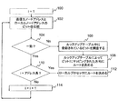
図9は、本発明に係る方法を示すフローチャートである。この方法は、ステップ100において、1つのノードのシステムスイッチ16がメッセージの送信先ノードアドレスの第1ビットを受信した場合に開始する。記述のために、いずれの時間においても考慮されるアドレスビットは、ここではビット番号iとしている。ステップ102において、送信先ノードアドレスのi番目のビットはローカルノードアドレスのi番目のビットと比較される。ステップ104において、送信先アドレスとローカルアドレスのi番目のビットが一致したか否かに基づいてこの方法は分岐する。それらが一致しない場合には、この方法は、i番目のビットに対してマッピングする方向を決定するためにルックアップテーブルを調査するステップ106に移行する。ステップ108において、メッセージはその方向にルーティングされる。送信先とローカルアドレスのi番目のビットが一致した場合には、この方法はノードアドレスが到達する最後のビットであるか否かを特定するステップ110に移行する。そうであれば、メッセージはその送信先に到着し、この方法は、メッセージがローカルプロセッサにルーティングされるステップ112に分岐する。最後のビットが到達してない場合には、この方法は次のアドレスビットを考慮するステップ114に移行し、ステップ102からの方法を繰り返す。
Like the example of FIG. 7, it has three degrees of freedom, left-right, up-down, and front-back. The example of FIG. 8 provides an
Node Node address Look-up table 1 0000 RDBY
2 0001 RDBG
3 0010 RDFY
4 0011 RDFG
5 0100 RUBY
6 0101 RUBG
7 0110 RUFY
8 0111 RUFG
9 1000 LDBY
10 1001 LDBG
11 1010 LDFY
12 1011 LDFG
13 1100 LUBY
14 1101 LUBG
15 1110 LUFY
16 1111 LUFG
FIG. 9 is a flowchart illustrating a method according to the present invention. The method starts when the system switch 16 of one node receives the first bit of the destination node address of the message at
上の記述から、ノードにアドレスを付け、対応するルックアップテーブルに割り当てる好ましい方法としてパターンがまた出現する。これは、図10のフローチャートを参照して説明する。ステップ200において、アレイにおける次元の数nを決定する。ステップ202において、Lをノードの数とする場合に、アレイの最大範囲L(k)は各次元k=1〜nに対して決定される。ステップ204において、座標は次元k=1〜nのそれぞれにおいて定義される。その座標はバイナリで連続しており、少なくともL(k)の長さをカバーしなければならない。各ノードの位置は、n次元のそれぞれにおけるそれぞれの座標によって記述されることができる。ステップ206において、m(k)ビットのアドレス部分は、各次元k=1〜nに沿って各ノードに対して制約2m(k)≧L(k)が割り当てられ、次元kに沿ったノードの座標はそれぞれのm(k)ビットのアドレス部分に格納されるように構成できる。ステップ208において、ノードアドレスビットに方向をマッピングすることにより、各ノードのためのルックアップテーブルが引き出される。アレイ中の各ノードの各アドレス部分に対して、これは、値0のビットにそれぞれの第1方向にマッピングし(例えば、右、下、後方、イエロー)、値1のビットにそれぞれ第2方向(例えば、左、上、前方、グリーン)をマッピングすることを意味する。
From the above description, patterns also emerge as a preferred method of addressing nodes and assigning them to corresponding lookup tables. This will be described with reference to the flowchart of FIG. In
たとえば、図7を再び参照すると、アドレスとこれに対応するルックアップテーブルは、以下のように割り当てられる。まず、アレイは3次元であり、3×3×2ノードの最大に拡張されている。21<3<22であることから、3つのノードの方は2ビットアドレス部分を必要とする。2つのノードの方は1ビットアドレス部分を必要とするだけである。これから、アレイはノードにアドレスを付与するために5ビットアドレスを用いるものであって、左−右方向においてノードにアドレスを付与するために2つの最上位ビットを用い、上−下方向においてノードにアドレスを付与するために3番目及び4番目の上位ビットを用い、前方−後方方向においては最下位ビットを用いる。ルックアップテーブルを引き出すために、2つの最上位ビットにおける右及び左、3番目及び4番目の上位ビットにおける下及び上、最下位ビットにおける後方及び前方に対してそれぞれ0及び1がマッピングされる。 For example, referring again to FIG. 7, the address and the corresponding lookup table are assigned as follows. First, the array is three dimensional and is expanded to a maximum of 3 × 3 × 2 nodes. Since 2 1 <3 <2 2 , the three nodes require a 2-bit address part. The two nodes only need a 1-bit address part. From now on, the array uses a 5-bit address to give the node an address, uses the two most significant bits to give the node an address in the left-right direction, and gives the node an up-down direction. The third and fourth upper bits are used to give the address, and the least significant bit is used in the forward-backward direction. To derive the lookup table, 0 and 1 are mapped to the right and left in the two most significant bits, the bottom and top in the third and fourth upper bits, and the back and front in the least significant bits, respectively.
上記実施例は単なる例証として記載したものであることはいうまでもない。他の実施例として、他のアドレスパターンは当業者にとって自明である。さらに、最上位から最下位ビットの順は、メッセージが平面の次に横列、その次に縦列の順でルーティングされるか、横列の次に平面、その次に縦列の順にルーティングされるかなどのように変更することが可能である。さらに、ルーティングルックアップテーブルは、ルーティングアルゴリズムのようなより好ましくないオプションによって置き換えることも可能である。たとえば、扱いやすい幾何学形状を形成しない不規則アレイやまたツリータイプ構造を有するアレイを含む、異なるサイズ、異なる形状、異なる次元数のアレイの例に対する他の構成は、当業者により実行可能である。本発明の観点は記述した実施例によって限定されるものではなく、以下のクレームによってのみ限定される。 It goes without saying that the above examples are described merely as examples. As other embodiments, other address patterns will be apparent to those skilled in the art. In addition, the order of most significant bit to least significant bit depends on whether the message is routed in the order of the row next to the plane, then the column, whether the message is routed in the order of the row, then the plane, and then the column. It is possible to change as follows. Furthermore, the routing lookup table can be replaced by less preferred options such as routing algorithms. Other configurations for examples of arrays of different sizes, shapes, and dimensions can be implemented by those skilled in the art, including, for example, irregular arrays that do not form manageable geometric shapes, or arrays that have a tree-type structure. . The aspects of the invention are not limited by the described embodiments, but only by the following claims.
Claims (39)
ローカルノードアドレスの要素を、それぞれ、他の1つのノードに向かうルーティング方向にマッピングするマッピング手段と、
送信先ノードを識別する送信先ノードアドレスを有するメッセージを受信するスイッチング手段であって、前記スイッチング手段は:最上位の不一致要素を識別することで、ローカルノードアドレスを送信先ノードアドレスと比較する手段と;ローカルノードアドレスが送信先ノードアドレスと一致しない場合に、マッピング手段により前記ローカルノードアドレスの最上位の不一致要素にマッピングされた方向に、他のノードにメッセージをルーティングする手段とを備える、スイッチング手段と、
を備えるプロセッサノードのアレイ。 Each node comprises a local node address identified in the array, each local node address comprising a plurality of elements having an order of address importance from top to bottom, each node comprising:
Mapping means for mapping each element of the local node address in a routing direction toward one other node;
Switching means for receiving a message having a destination node address identifying a destination node, the switching means: means for comparing a local node address with a destination node address by identifying the highest level mismatch element And means for routing a message to another node in a direction mapped by the mapping means to the highest mismatched element of the local node address when the local node address does not match the destination node address. Means,
An array of processor nodes comprising:
送信先ノードアドレスを備えるメッセージを1つのノードにおいて受信し;
最上位の不一致要素を識別するために前記ローカルノードアドレスを前記送信先ノードアドレスと比較し;
前記ローカルノードアドレスが前記送信先ノードアドレスと一致しない場合に、前記ローカルノードアドレスの各要素を、それぞれ、他の1つのノードに向かうルーティング方向にマッピングするマッピング手段を調査し、前記マッピング手段により前記ローカルノードアドレスの最上位の不一致要素にマッピングされた方向にある他のノードに前記メッセージをルーティングする、方法。 A method for routing messages in an array of processor nodes, each node having a local node address for identification within the array, wherein each local node address is in order of address importance from highest to lowest. Wherein the method comprises:
Receiving a message comprising a destination node address at one node;
Comparing the local node address with the destination node address to identify the highest level mismatch element;
When the local node address does not match the destination node address, a mapping unit that maps each element of the local node address in a routing direction toward another one node is investigated, and the mapping unit A method of routing the message to other nodes in the direction mapped to the highest mismatch element of the local node address.
アレイ中の次元の数nを決定し;
Lをノードの数とするとき、次元k=1〜nのそれぞれにおいてアレイの最大範囲L(k)を決定し;
各次元k=1〜nに沿って、バイナリで連続的に番号が付された座標を定義し、この座標は少なくともL(k)の長さをカバーしており、そのようなノードは各n次元中のそれぞれの座標により記述される;
各次元k=1〜nに沿って各ノードをアドレスするために、2m(k)≧L(k)となるようなm(k)ビットのアドレス部分を割り当て、それぞれのm(k)ビットアドレス部分中の各次元kに沿ったノード座標を格納し;
アレイ中の各ノードの各アドレス部分に対して、値0のビットに、それぞれ、他の1つのノードに向かう第1方向をマッピングし、値1のビットに、それぞれ、別の他の1つのノードに向かう第2方向をマッピングし;
複数の前記アドレス及び前記方向を参照することによってメッセージをルーティングする、方法。 A method for routing messages between nodes of an n-dimensional processor array, where n is an integer, the method comprising:
Determining the number n of dimensions in the array;
Determine the maximum range L (k) of the array in each of the dimensions k = 1 to n, where L is the number of nodes;
Along each dimension k = 1 to n, define a binary consecutively numbered coordinate, which covers at least a length of L (k), such a node for each n Described by coordinates in each dimension;
To address each node along each dimension k = 1 to n, an m (k) bit address portion is assigned such that 2 m (k) ≧ L (k), and each m (k) bit Store the node coordinates along each dimension k in the address part;
For each address portion of each node in the array, map the first direction towards the other one node to each bit of value 0, and each of the other one node to each bit of value 1 Map the second direction towards
A method for routing a message by referencing a plurality of the addresses and the direction.
前記プログラムは、
アレイ中の次元の数nを決定するステップ;
Lをノードの数とするとき、次元k=1〜nのそれぞれにおいてアレイの最大範囲L(k)を決定するステップ;
次元k=1〜nのそれぞれに沿って、バイナリで連続的に番号が付された座標を定義し、この座標は少なくともL(k)の長さをカバーしており、そのようなノードは各n次元中のそれぞれの座標により記述される;
各次元k=1〜nに沿って各ノードをアドレスするために、2m(k)≧L(k)となるようなm(k)ビットのアドレス部分を割り当て、それぞれのm(k)ビットアドレス部分中の各次元kに沿って、ノード座標を格納するステップ;
アレイ中の各ノードの各アドレス部分に対して、値0のビットに、それぞれ、他の1つのノードに向かう第1方向をマッピングし、値1のビットに、それぞれ、別の他の1つのノードに向かう第2方向をマッピングするステップ
を前記コンピュータに実行させるためのプログラム。 When n is an integer, a program for executing the process of assigning addresses to the nodes of an n-dimensional processor array computer,
Before Kipu program is,
Determining a number n of dimensions in the array;
When the L to the number of nodes, determining the maximum range of the array L (k) in each dimension k = 1 to n;
Along each of the dimensions k = 1 to n, define a binary sequentially numbered coordinate, which covers at least a length of L (k), such a node for each described by their coordinates in n dimensions;
To address each node along each dimension k = 1 to n, an m (k) bit address portion is assigned such that 2 m (k) ≧ L (k), and each m (k) bit along each dimension k in the partial address, storing the node coordinates;
For each address portion of each node in the array, map the first direction towards the other one node to each bit of value 0, and each of the other one node to each bit of value 1 step of mapping the second direction towards the
For causing the computer to execute .
前記ローカルノードアドレスの各要素に、それぞれ、他の1つのノードに向かうルーティング方向をマッピングするマッピング装置と、
送信先ノードを識別するための送信先ノードアドレスを有するメッセージを受信するための配置されるスイッチと、
を備え、前記スイッチは、
最上位の不一致要素を識別することにより、前記ローカルノードアドレスを前記送信先ノードアドレスと比較するための比較部と、
前記ローカルノードアドレスが前記送信先ノードアドレスと一致しなかった場合に、前記マッピング装置により前記ローカルノードアドレスの最上位の不一致要素にマッピングされた方向にある、他のノードに前記メッセージをルーティングするルーティング部と、
を備えるアレイ。 An array of processor nodes, each node having a local node address for identification in the array, each local node address comprising a plurality of elements having an order of highest to lowest address importance; Each node
A mapping device for mapping a routing direction toward another one node to each element of the local node address;
A switch arranged to receive a message having a destination node address for identifying the destination node;
The switch comprises:
A comparison unit for comparing the local node address with the destination node address by identifying the highest level mismatch element;
Routing for routing the message to another node in the direction mapped by the mapping device to the highest mismatched element of the local node address when the local node address does not match the destination node address And
An array.
Applications Claiming Priority (3)
| Application Number | Priority Date | Filing Date | Title |
|---|---|---|---|
| US11/717,621 | 2007-03-14 | ||
| US11/717,621 US7962717B2 (en) | 2007-03-14 | 2007-03-14 | Message routing scheme |
| PCT/GB2008/000880 WO2008110806A1 (en) | 2007-03-14 | 2008-03-13 | Message routing scheme |
Publications (2)
| Publication Number | Publication Date |
|---|---|
| JP2010521731A JP2010521731A (en) | 2010-06-24 |
| JP5398552B2 true JP5398552B2 (en) | 2014-01-29 |
Family
ID=39430991
Family Applications (1)
| Application Number | Title | Priority Date | Filing Date |
|---|---|---|---|
| JP2009553208A Active JP5398552B2 (en) | 2007-03-14 | 2008-03-13 | Message routing structure |
Country Status (8)
| Country | Link |
|---|---|
| US (2) | US7962717B2 (en) |
| EP (1) | EP2140365B1 (en) |
| JP (1) | JP5398552B2 (en) |
| KR (1) | KR101415286B1 (en) |
| CN (1) | CN101689172B (en) |
| AT (1) | ATE492851T1 (en) |
| DE (1) | DE602008004130D1 (en) |
| WO (1) | WO2008110806A1 (en) |
Families Citing this family (38)
| Publication number | Priority date | Publication date | Assignee | Title |
|---|---|---|---|---|
| KR20100084605A (en) * | 2007-05-31 | 2010-07-27 | 더 유니버시티 오브 레딩 | Processor |
| US9092212B2 (en) | 2007-05-31 | 2015-07-28 | James Arthur Dean Wallace Anderson | Processors |
| US8122228B2 (en) * | 2008-03-24 | 2012-02-21 | International Business Machines Corporation | Broadcasting collective operation contributions throughout a parallel computer |
| US8484440B2 (en) | 2008-05-21 | 2013-07-09 | International Business Machines Corporation | Performing an allreduce operation on a plurality of compute nodes of a parallel computer |
| US7958341B1 (en) | 2008-07-07 | 2011-06-07 | Ovics | Processing stream instruction in IC of mesh connected matrix of processors containing pipeline coupled switch transferring messages over consecutive cycles from one link to another link or memory |
| US8327114B1 (en) * | 2008-07-07 | 2012-12-04 | Ovics | Matrix processor proxy systems and methods |
| US8145880B1 (en) | 2008-07-07 | 2012-03-27 | Ovics | Matrix processor data switch routing systems and methods |
| US8131975B1 (en) | 2008-07-07 | 2012-03-06 | Ovics | Matrix processor initialization systems and methods |
| US8050256B1 (en) | 2008-07-08 | 2011-11-01 | Tilera Corporation | Configuring routing in mesh networks |
| US8151088B1 (en) * | 2008-07-08 | 2012-04-03 | Tilera Corporation | Configuring routing in mesh networks |
| US8045546B1 (en) | 2008-07-08 | 2011-10-25 | Tilera Corporation | Configuring routing in mesh networks |
| US8281053B2 (en) | 2008-07-21 | 2012-10-02 | International Business Machines Corporation | Performing an all-to-all data exchange on a plurality of data buffers by performing swap operations |
| NL2002799C2 (en) * | 2009-04-24 | 2010-10-26 | Univ Delft Tech | Data structure, method and system for address lookup. |
| US8539155B1 (en) * | 2009-09-21 | 2013-09-17 | Tilera Corporation | Managing home cache assignment |
| CN102130813B (en) * | 2010-01-15 | 2016-08-03 | 华为技术有限公司 | Pseudowire establishment method, system and equipment |
| US8665727B1 (en) * | 2010-06-21 | 2014-03-04 | Xilinx, Inc. | Placement and routing for a multiplexer-based interconnection network |
| US8910178B2 (en) | 2011-08-10 | 2014-12-09 | International Business Machines Corporation | Performing a global barrier operation in a parallel computer |
| US9495135B2 (en) | 2012-02-09 | 2016-11-15 | International Business Machines Corporation | Developing collective operations for a parallel computer |
| KR101506208B1 (en) * | 2013-02-13 | 2015-03-26 | 라이트웍스 주식회사 | Method for comprising preamble of ethernet for routing of network on chip |
| US10218524B2 (en) | 2013-09-17 | 2019-02-26 | Cisco Technology, Inc. | Bit indexed explicit replication for layer 2 networking |
| US9853822B2 (en) | 2013-09-17 | 2017-12-26 | Cisco Technology, Inc. | Bit indexed explicit replication |
| US11451474B2 (en) | 2013-09-17 | 2022-09-20 | Cisco Technology, Inc. | Equal cost multi-path with bit indexed explicit replication |
| US9806897B2 (en) | 2013-09-17 | 2017-10-31 | Cisco Technology, Inc. | Bit indexed explicit replication forwarding optimization |
| US10003494B2 (en) | 2013-09-17 | 2018-06-19 | Cisco Technology, Inc. | Per-prefix LFA FRR with bit indexed explicit replication |
| US10461946B2 (en) | 2013-09-17 | 2019-10-29 | Cisco Technology, Inc. | Overlay signaling for bit indexed explicit replication |
| US9906378B2 (en) | 2015-01-27 | 2018-02-27 | Cisco Technology, Inc. | Capability aware routing |
| US10341221B2 (en) | 2015-02-26 | 2019-07-02 | Cisco Technology, Inc. | Traffic engineering for bit indexed explicit replication |
| US10116557B2 (en) | 2015-05-22 | 2018-10-30 | Gray Research LLC | Directional two-dimensional router and interconnection network for field programmable gate arrays, and other circuits and applications of the router and network |
| US20170220499A1 (en) * | 2016-01-04 | 2017-08-03 | Gray Research LLC | Massively parallel computer, accelerated computing clusters, and two-dimensional router and interconnection network for field programmable gate arrays, and applications |
| US10630743B2 (en) | 2016-09-23 | 2020-04-21 | Cisco Technology, Inc. | Unicast media replication fabric using bit indexed explicit replication |
| US10637675B2 (en) | 2016-11-09 | 2020-04-28 | Cisco Technology, Inc. | Area-specific broadcasting using bit indexed explicit replication |
| US10496578B2 (en) | 2017-01-06 | 2019-12-03 | Samsung Electronics Co., Ltd. | Central arbitration scheme for a highly efficient interconnection topology in a GPU |
| US10447496B2 (en) | 2017-03-30 | 2019-10-15 | Cisco Technology, Inc. | Multicast traffic steering using tree identity in bit indexed explicit replication (BIER) |
| US10587534B2 (en) | 2017-04-04 | 2020-03-10 | Gray Research LLC | Composing cores and FPGAS at massive scale with directional, two dimensional routers and interconnection networks |
| US10164794B2 (en) | 2017-04-28 | 2018-12-25 | Cisco Technology, Inc. | Bridging of non-capable subnetworks in bit indexed explicit replication |
| CN109117333B (en) * | 2018-09-29 | 2023-04-07 | 深圳比特微电子科技有限公司 | Computing chip and operation method thereof |
| CN116578522B (en) * | 2023-07-13 | 2023-12-01 | 中电海康集团有限公司 | Data processing method, device, equipment and storage medium based on many-core architecture |
| GB2643878A (en) * | 2024-09-03 | 2026-03-11 | Riverlane Ltd | Quantum decoder |
Family Cites Families (34)
| Publication number | Priority date | Publication date | Assignee | Title |
|---|---|---|---|---|
| US4814973A (en) * | 1983-05-31 | 1989-03-21 | Hillis W Daniel | Parallel processor |
| US4661947A (en) * | 1984-09-26 | 1987-04-28 | American Telephone And Telegraph Company At&T Bell Laboratories | Self-routing packet switching network with intrastage packet communication |
| US4651318A (en) * | 1984-11-30 | 1987-03-17 | At&T Bell Laboratories | Self-routing packets with stage address identifying fields |
| US4679189A (en) * | 1985-11-27 | 1987-07-07 | American Telephone And Telegraph Company | Alternate routing arrangement |
| JP2635031B2 (en) * | 1986-11-14 | 1997-07-30 | 株式会社日立製作所 | Mutual coupling of parallel computers |
| US5008882A (en) * | 1987-08-17 | 1991-04-16 | California Institute Of Technology | Method and apparatus for eliminating unsuccessful tries in a search tree |
| JPH01126760A (en) * | 1987-11-11 | 1989-05-18 | Toshiba Corp | Parallel computer system |
| US5422881A (en) * | 1989-06-30 | 1995-06-06 | Inmos Limited | Message encoding |
| GB8915135D0 (en) * | 1989-06-30 | 1989-08-23 | Inmos Ltd | Message routing |
| JPH05303558A (en) * | 1991-12-13 | 1993-11-16 | Nec Corp | Method and device for message packet routing of array processor |
| JPH06243113A (en) * | 1993-02-19 | 1994-09-02 | Fujitsu Ltd | Mapping Method of Computation Model on Parallel Computer |
| JP3283319B2 (en) * | 1993-03-02 | 2002-05-20 | 松下電器産業株式会社 | Processor element and parallel processing system |
| US5583990A (en) * | 1993-12-10 | 1996-12-10 | Cray Research, Inc. | System for allocating messages between virtual channels to avoid deadlock and to optimize the amount of message traffic on each type of virtual channel |
| US5430729A (en) * | 1994-04-04 | 1995-07-04 | Motorola, Inc. | Method and apparatus for adaptive directed route randomization and distribution in a richly connected communication network |
| US5539739A (en) * | 1994-09-29 | 1996-07-23 | Intel Corporation | Asynchronous interface between parallel processor nodes |
| JPH08185380A (en) * | 1994-12-28 | 1996-07-16 | Hitachi Ltd | Parallel computer |
| US5926101A (en) * | 1995-11-16 | 1999-07-20 | Philips Electronics North America Corporation | Method and apparatus for routing messages in a network of nodes with minimal resources |
| CN1094008C (en) * | 1995-07-28 | 2002-11-06 | 英国电讯有限公司 | Packet routing |
| US5602839A (en) * | 1995-11-09 | 1997-02-11 | International Business Machines Corporation | Adaptive and dynamic message routing system for multinode wormhole networks |
| US6842430B1 (en) * | 1996-10-16 | 2005-01-11 | Koninklijke Philips Electronics N.V. | Method for configuring and routing data within a wireless multihop network and a wireless network for implementing the same |
| SE9604491L (en) * | 1996-12-05 | 1998-06-06 | Ericsson Telefon Ab L M | Device and method of transmission system |
| US6226710B1 (en) * | 1997-11-14 | 2001-05-01 | Utmc Microelectronic Systems Inc. | Content addressable memory (CAM) engine |
| US6230252B1 (en) * | 1997-11-17 | 2001-05-08 | Silicon Graphics, Inc. | Hybrid hypercube/torus architecture |
| US6643764B1 (en) * | 2000-07-20 | 2003-11-04 | Silicon Graphics, Inc. | Multiprocessor system utilizing multiple links to improve point to point bandwidth |
| US6982976B2 (en) * | 2000-08-11 | 2006-01-03 | Texas Instruments Incorporated | Datapipe routing bridge |
| US20030031126A1 (en) * | 2001-03-12 | 2003-02-13 | Mayweather Derek T. | Bandwidth reservation reuse in dynamically allocated ring protection and restoration technique |
| US7027413B2 (en) * | 2001-09-28 | 2006-04-11 | Sun Microsystems, Inc. | Discovery of nodes in an interconnection fabric |
| WO2003038645A2 (en) * | 2001-10-31 | 2003-05-08 | University Of Texas | A scalable processing architecture |
| US7581081B2 (en) * | 2003-03-31 | 2009-08-25 | Stretch, Inc. | Systems and methods for software extensible multi-processing |
| US7369561B2 (en) * | 2003-07-17 | 2008-05-06 | Samsung Electronics Co., Ltd. | Apparatus and method for route summarization and distribution in a massively parallel router |
| KR101200598B1 (en) * | 2003-09-09 | 2012-11-12 | 실리콘 하이브 비.브이. | Integrated data processing circuit with a plurality of programmable processors |
| US7349981B2 (en) * | 2003-12-18 | 2008-03-25 | Intel Corporation | System, apparatus, and method for string matching |
| CN100377065C (en) * | 2006-04-19 | 2008-03-26 | 华中科技大学 | A super large capacity virtual disk storage system |
| US20100250784A1 (en) * | 2009-03-26 | 2010-09-30 | Terascale Supercomputing Inc. | Addressing Scheme and Message Routing for a Networked Device |
-
2007
- 2007-03-14 US US11/717,621 patent/US7962717B2/en active Active
-
2008
- 2008-03-13 KR KR1020097021479A patent/KR101415286B1/en active Active
- 2008-03-13 CN CN2008800149822A patent/CN101689172B/en active Active
- 2008-03-13 EP EP08718722A patent/EP2140365B1/en active Active
- 2008-03-13 JP JP2009553208A patent/JP5398552B2/en active Active
- 2008-03-13 WO PCT/GB2008/000880 patent/WO2008110806A1/en not_active Ceased
- 2008-03-13 AT AT08718722T patent/ATE492851T1/en not_active IP Right Cessation
- 2008-03-13 DE DE602008004130T patent/DE602008004130D1/en active Active
-
2010
- 2010-11-18 US US12/949,690 patent/US8185719B2/en active Active
Also Published As
| Publication number | Publication date |
|---|---|
| US20110066825A1 (en) | 2011-03-17 |
| DE602008004130D1 (en) | 2011-02-03 |
| KR20100015586A (en) | 2010-02-12 |
| WO2008110806A8 (en) | 2009-11-19 |
| ATE492851T1 (en) | 2011-01-15 |
| WO2008110806A1 (en) | 2008-09-18 |
| JP2010521731A (en) | 2010-06-24 |
| CN101689172A (en) | 2010-03-31 |
| EP2140365A1 (en) | 2010-01-06 |
| US20080229059A1 (en) | 2008-09-18 |
| EP2140365B1 (en) | 2010-12-22 |
| CN101689172B (en) | 2012-03-28 |
| US7962717B2 (en) | 2011-06-14 |
| KR101415286B1 (en) | 2014-07-04 |
| US8185719B2 (en) | 2012-05-22 |
Similar Documents
| Publication | Publication Date | Title |
|---|---|---|
| JP5398552B2 (en) | Message routing structure | |
| KR102637136B1 (en) | A matrix of on-chip routers interconnecting a plurality of processing engines and a method of routing using thereof | |
| Gindin et al. | NoC-based FPGA: architecture and routing | |
| JP4734539B2 (en) | System and method for searching for the shortest path between nodes in a network | |
| US8601423B1 (en) | Asymmetric mesh NoC topologies | |
| US8243733B2 (en) | Cascaded memory tables for searching | |
| JP6751819B2 (en) | Packet transmission | |
| KR102594944B1 (en) | System and method for synthesis of a network-on-chip for deadlock-free transformation | |
| EP3278520B1 (en) | Distributed routing table system with improved support for multiple network topologies | |
| US9397957B2 (en) | Traffic engineering for large scale data center networks | |
| US6549954B1 (en) | Object oriented on-chip messaging | |
| JP5665208B2 (en) | Optimizing data transmission within a hypercube network | |
| US10409738B2 (en) | Information switching | |
| CN119728524B (en) | A data packet transmission method, electronic device, storage medium and product | |
| US11010322B1 (en) | NOC peripheral interconnect interrogation scheme | |
| CN112217730B (en) | Network routing using aggregated links | |
| US20090313413A1 (en) | method for wiring allocation and switch configuration in a multiprocessor environment |
Legal Events
| Date | Code | Title | Description |
|---|---|---|---|
| A621 | Written request for application examination |
Free format text: JAPANESE INTERMEDIATE CODE: A621 Effective date: 20110221 |
|
| A131 | Notification of reasons for refusal |
Free format text: JAPANESE INTERMEDIATE CODE: A131 Effective date: 20121204 |
|
| A601 | Written request for extension of time |
Free format text: JAPANESE INTERMEDIATE CODE: A601 Effective date: 20130304 |
|
| A602 | Written permission of extension of time |
Free format text: JAPANESE INTERMEDIATE CODE: A602 Effective date: 20130311 |
|
| A521 | Request for written amendment filed |
Free format text: JAPANESE INTERMEDIATE CODE: A523 Effective date: 20130404 |
|
| A131 | Notification of reasons for refusal |
Free format text: JAPANESE INTERMEDIATE CODE: A131 Effective date: 20130507 |
|
| A521 | Request for written amendment filed |
Free format text: JAPANESE INTERMEDIATE CODE: A523 Effective date: 20130807 |
|
| TRDD | Decision of grant or rejection written | ||
| A01 | Written decision to grant a patent or to grant a registration (utility model) |
Free format text: JAPANESE INTERMEDIATE CODE: A01 Effective date: 20130924 |
|
| A61 | First payment of annual fees (during grant procedure) |
Free format text: JAPANESE INTERMEDIATE CODE: A61 Effective date: 20131022 |
|
| R150 | Certificate of patent or registration of utility model |
Ref document number: 5398552 Country of ref document: JP Free format text: JAPANESE INTERMEDIATE CODE: R150 Free format text: JAPANESE INTERMEDIATE CODE: R150 |
|
| R250 | Receipt of annual fees |
Free format text: JAPANESE INTERMEDIATE CODE: R250 |
|
| R250 | Receipt of annual fees |
Free format text: JAPANESE INTERMEDIATE CODE: R250 |
|
| R250 | Receipt of annual fees |
Free format text: JAPANESE INTERMEDIATE CODE: R250 |
|
| R250 | Receipt of annual fees |
Free format text: JAPANESE INTERMEDIATE CODE: R250 |
|
| R250 | Receipt of annual fees |
Free format text: JAPANESE INTERMEDIATE CODE: R250 |
|
| R250 | Receipt of annual fees |
Free format text: JAPANESE INTERMEDIATE CODE: R250 |
|
| R250 | Receipt of annual fees |
Free format text: JAPANESE INTERMEDIATE CODE: R250 |
|
| S531 | Written request for registration of change of domicile |
Free format text: JAPANESE INTERMEDIATE CODE: R313531 |
|
| R350 | Written notification of registration of transfer |
Free format text: JAPANESE INTERMEDIATE CODE: R350 |
|
| R250 | Receipt of annual fees |
Free format text: JAPANESE INTERMEDIATE CODE: R250 |
|
| R250 | Receipt of annual fees |
Free format text: JAPANESE INTERMEDIATE CODE: R250 |
|
| R250 | Receipt of annual fees |
Free format text: JAPANESE INTERMEDIATE CODE: R250 |