JP5397151B2 - HEATER CONTROL DEVICE, IMAGE FORMING DEVICE, HEATER CONTROL METHOD, AND PROGRAM - Google Patents
HEATER CONTROL DEVICE, IMAGE FORMING DEVICE, HEATER CONTROL METHOD, AND PROGRAM Download PDFInfo
- Publication number
- JP5397151B2 JP5397151B2 JP2009240887A JP2009240887A JP5397151B2 JP 5397151 B2 JP5397151 B2 JP 5397151B2 JP 2009240887 A JP2009240887 A JP 2009240887A JP 2009240887 A JP2009240887 A JP 2009240887A JP 5397151 B2 JP5397151 B2 JP 5397151B2
- Authority
- JP
- Japan
- Prior art keywords
- ratio
- lighting
- cumulative
- heater
- cumulative ratio
- Prior art date
- Legal status (The legal status is an assumption and is not a legal conclusion. Google has not performed a legal analysis and makes no representation as to the accuracy of the status listed.)
- Expired - Fee Related
Links
Images


Description
本発明は、ヒータの点灯を制御するヒータ制御装置、画像形成装置、ヒータ制御方法およびプログラムに関する。 The present invention relates to a heater control device that controls lighting of a heater, an image forming apparatus, a heater control method, and a program.
電子写真方式の画像形成装置に用いられる定着ヒータには、ハロゲンヒータが広く用いられている。ハロゲンヒータは、突入電流を大きく流し、立ち上がり時間が短いことが特徴であるが、突入電流が大きいため、配線インピーダンスにおいて電圧変動(フリッカ)が生じ、屋内の電灯のちらつきの原因となっている。 A halogen heater is widely used as a fixing heater used in an electrophotographic image forming apparatus. The halogen heater is characterized by a large inrush current and a short rise time. However, since the inrush current is large, voltage fluctuation (flicker) occurs in the wiring impedance, causing flickering of the indoor lamp.
突入電流の抑制を目的として、上述の高周波点灯パターンの直前に半波長の一部のみヒータをオンし、徐々にオン時間を長くする位相制御(ソフトスタート)を導入する技術が提案されている(例えば、特許文献1参照)。 For the purpose of suppressing inrush current, a technique has been proposed that introduces phase control (soft start) to turn on the heater only for a part of the half-wavelength immediately before the above-described high-frequency lighting pattern and gradually increase the on-time ( For example, see Patent Document 1).
位相制御においては、高調波電流が流れ、高調波電流や雑音端子電圧の規制値を満たさないなどの副作用が発生する。そこで、位相角(点灯タイミング)を、各規制値(雑音端子電圧、高調波電流、フリッカ)を満足する値に調整するという対策をとってきた。しかしながら、位相制御による調整評価では、規格を満足する点灯タイミングや回数等を見出す対策評価時間が長くなったり、位相制御により発生する高調波電流の抑制を目的としてチョークコイルなどフィルタ回路を大きくするための対策コストが発生したりすることが問題となっている。 In phase control, harmonic current flows, and side effects such as not satisfying the regulation values of harmonic current and noise terminal voltage occur. Therefore, a measure has been taken to adjust the phase angle (lighting timing) to a value that satisfies each regulation value (noise terminal voltage, harmonic current, flicker). However, in the adjustment evaluation by phase control, the measure evaluation time for finding the lighting timing and the number of times satisfying the standard becomes longer, or the filter circuit such as the choke coil is enlarged for the purpose of suppressing the harmonic current generated by the phase control. It is a problem that the cost of countermeasures is incurred.
これに対し、人間の目に敏感に感じるとされるちらつきの周波数帯(8.8〜10Hz)に対し、ヒータの点灯制御が約10Hz帯域のスイッチングにならないように、または周波数成分が極力小さくなるように、ちらつきの対象となる周波数に近い10半波長(100ms)周期の半波サイクル単位で点灯パターンを制御する技術が知られている(例えば、特許文献2参照)。 On the other hand, with respect to the flicker frequency band (8.8 to 10 Hz) that is considered to be sensitive to human eyes, the lighting component of the heater is not switched to about 10 Hz band, or the frequency component is minimized. As described above, a technique for controlling the lighting pattern in units of half-wave cycles with a period of 10 half wavelengths (100 ms) close to the frequency to be flickered is known (see, for example, Patent Document 2).
しかしながら、10半波長周期の半波サイクル単位での点灯パターンのヒータ制御においては、点灯デューティ(点灯比率)によるフリッカレベルの差が生じており、低デューティ(10〜30%付近)では、中デューティ(40〜60%付近)と比較し周波数特性が劣っておりフリッカレベルが悪い傾向にあることがわかっている。 However, in the heater control of the lighting pattern in a half wave cycle unit of 10 half wavelength cycles, a difference in flicker level occurs due to the lighting duty (lighting ratio), and at a low duty (around 10 to 30%), a medium duty is generated. It is known that the frequency characteristics are inferior compared to (around 40 to 60%) and the flicker level tends to be poor.
本発明は、上記に鑑みてなされたものであって、点灯比率によらず、高調波電流、雑音端子電圧のレベル悪化を抑制しつつ、フリッカレベルを改善することのできるヒータ制御装置、画像形成装置、ヒータ制御方法およびプログラムを提供することを目的とする。 The present invention has been made in view of the above, and is a heater control device capable of improving the flicker level while suppressing the deterioration of the level of the harmonic current and the noise terminal voltage regardless of the lighting ratio, and image formation An object is to provide an apparatus, a heater control method, and a program.
上述した課題を解決し、目的を達成するために、本発明は、ヒータ制御装置であって、ヒータにより加熱される加熱対象物の温度を検出する温度検出手段と、前記ヒータに交流電圧を印加する交流電源と、前記加熱対象物の温度と目標温度に基づいて、前記ヒータの点灯比率を決定する点灯比率決定手段と、所定の制御周期を単位とするパターンであって、フリッカを回避するように、前記制御周期内の前記交流電圧の半波長に全点灯または全消灯が割り当てられた点灯パターンを記憶する点灯パターン記憶手段と、前記点灯比率決定手段によりこれまでに決定された点灯比率の累積値である累積比率を記憶する累積比率記憶手段と、前記点灯比率決定手段により前記点灯比率が決定された場合に、前記累積比率記憶手段に記憶されている前記累積比率に新たに決定された前記点灯比率を加算した値を新たな前記累積比率として前記累積比率記憶手段に記憶する累積比率管理手段と、前記加熱対象物による動作が行われていない待機状態であってかつ前記累積比率記憶手段に記憶されている前記累積比率が予め設定された第1閾値未満の場合に前記ヒータを消灯させ、前記待機状態であって、前記累積比率記憶手段に記憶されている前記累積比率が前記第1閾値よりも大きい第2閾値よりも大きい場合に前記ヒータを前記点灯比率100%で点灯させ、前記待機状態であって、前記累積比率記憶手段に記憶されている前記累積比率が前記第1閾値以上であってかつ前記第2閾値以下である場合に前記ヒータを前記累積比率に対応する前記点灯パターンで点灯させる点灯制御手段とを備えたことを特徴とする。 In order to solve the above-mentioned problems and achieve the object, the present invention is a heater control device, which is a temperature detecting means for detecting the temperature of a heating object heated by the heater, and an AC voltage is applied to the heater. An alternating current power supply, a lighting ratio determining means for determining a lighting ratio of the heater based on the temperature and target temperature of the heating object, and a pattern with a predetermined control cycle as a unit so as to avoid flicker A lighting pattern storage means for storing a lighting pattern in which full lighting or full lighting is assigned to a half wavelength of the AC voltage within the control cycle, and a cumulative lighting ratio determined so far by the lighting ratio determining means A cumulative ratio storage means for storing a cumulative ratio that is a value, and when the lighting ratio is determined by the lighting ratio determination means, before being stored in the cumulative ratio storage means In a standby state where the operation by the heating object is not performed, the cumulative ratio management means for storing the value obtained by adding the newly determined lighting ratio to the cumulative ratio in the cumulative ratio storage means as the new cumulative ratio And when the cumulative ratio stored in the cumulative ratio storage means is less than a preset first threshold value, the heater is turned off, is in the standby state, and is stored in the cumulative ratio storage means. The heater is turned on at the lighting ratio of 100% when the cumulative ratio is greater than a second threshold value that is greater than the first threshold value, and is in the standby state and stored in the cumulative ratio storage means. Lighting control means for lighting the heater in the lighting pattern corresponding to the cumulative ratio when the cumulative ratio is equal to or greater than the first threshold and equal to or smaller than the second threshold; And said that there were pictures.
また、本発明の他の形態は、画像形成装置であって、ヒータにより加熱される加熱対象物の温度を検出する温度検出手段と、前記ヒータに交流電圧を印加する交流電源と、前記加熱対象物の温度と目標温度に基づいて、前記ヒータの点灯比率を決定する点灯比率決定手段と、所定の制御周期を単位とするパターンであって、フリッカを回避するように、前記制御周期内の前記交流電圧の半波長に全点灯または全消灯が割り当てられた点灯パターンを記憶する点灯パターン記憶手段と、前記点灯比率決定手段によりこれまでに決定された点灯比率の累積値である累積比率を記憶する累積比率記憶手段と、前記点灯比率決定手段により前記点灯比率が決定された場合に、前記累積比率記憶手段に記憶されている前記累積比率に新たに決定された前記点灯比率を加算した値を新たな前記累積比率として前記累積比率記憶手段に記憶する累積比率管理手段と、前記加熱対象物による動作が行われていない待機状態であってかつ前記累積比率記憶手段に記憶されている前記累積比率が予め設定された第1閾値未満の場合に前記ヒータを消灯させ、前記待機状態であって、前記累積比率記憶手段に記憶されている前記累積比率が前記第1閾値よりも大きい第2閾値よりも大きい場合に前記ヒータを前記点灯比率100%で点灯させ、前記待機状態であって、前記累積比率記憶手段に記憶されている前記累積比率が前記第1閾値以上であってかつ前記第2閾値以下である場合に前記ヒータを前記累積比率に対応する前記点灯パターンで点灯させる点灯制御手段とを備えたことを特徴とする。 According to another aspect of the present invention, there is provided an image forming apparatus including a temperature detecting unit that detects a temperature of an object to be heated by a heater, an AC power source that applies an AC voltage to the heater, and the heating object. A lighting ratio determining means for determining a lighting ratio of the heater based on the temperature of the object and a target temperature; and a pattern having a predetermined control period as a unit, and the flicker within the control period so as to avoid flicker A lighting pattern storage means for storing a lighting pattern in which full lighting or full lighting is assigned to a half wavelength of the AC voltage, and a cumulative ratio that is a cumulative value of the lighting ratio determined so far by the lighting ratio determination means is stored. When the lighting ratio is determined by the cumulative ratio storage unit and the lighting ratio determination unit, the cumulative ratio stored in the cumulative ratio storage unit is newly determined. A cumulative ratio management means for storing a value obtained by adding the lighting ratio as a new cumulative ratio in the cumulative ratio storage means, and a standby state in which an operation by the heating object is not performed, and the cumulative ratio storage means When the stored cumulative ratio is less than a preset first threshold value, the heater is turned off, and in the standby state, the cumulative ratio stored in the cumulative ratio storage means is the first threshold value. The heater is turned on at the lighting ratio of 100% when it is larger than the second threshold value greater than the second threshold value, is in the standby state, and the cumulative ratio stored in the cumulative ratio storage means is greater than or equal to the first threshold value. And a lighting control means for lighting the heater with the lighting pattern corresponding to the cumulative ratio when it is equal to or less than the second threshold value.
また、本発明の他の形態は、ヒータ制御装置で実行されるヒータ制御方法であって、前記ヒータ制御装置は、所定の制御周期を単位とするパターンであって、フリッカを回避するように、前記制御周期内の前記交流電圧の半波長に全点灯または全消灯が割り当てられた点灯パターンを記憶する点灯パターン記憶手段と、前記ヒータの点灯比率の累積値である累積比率を記憶する累積比率記憶手段とを備え、前記加熱対象物の温度と目標温度に基づいて、前記ヒータの点灯比率を決定する点灯比率決定ステップと、前記点灯比率決定ステップで、これまでに決定された点灯比率の累積値である累積比率を前記累積比率記憶手段に記憶する記憶ステップと、前記点灯比率決定ステップで前記点灯比率が決定された場合に、前記累積比率記憶手段に記憶されている前記累積比率に新たに決定された前記点灯比率を加算した値を新たな前記累積比率として前記累積比率記憶手段に記憶する累積比率管理ステップと、前記加熱対象物による動作が行われていない待機状態であってかつ前記累積比率記憶手段に記憶されている前記累積比率が予め設定された第1閾値未満の場合に前記ヒータを消灯させ、前記待機状態であって、前記累積比率記憶手段に記憶されている前記累積比率が前記第1閾値よりも大きい第2閾値よりも大きい場合に前記ヒータを前記点灯比率100%で点灯させ、前記待機状態であって、前記累積比率記憶手段に記憶されている前記累積比率が前記第1閾値以上であってかつ前記第2閾値以下である場合に前記ヒータを前記累積比率に対応する前記点灯パターンで点灯させる点灯制御ステップとを有することを特徴とする。 According to another aspect of the present invention, there is provided a heater control method executed by a heater control device, wherein the heater control device is a pattern having a predetermined control cycle as a unit, and avoids flicker. A lighting pattern storage means for storing a lighting pattern in which full lighting or full lighting is assigned to a half wavelength of the AC voltage within the control cycle, and a cumulative ratio memory for storing a cumulative ratio that is a cumulative value of the lighting ratio of the heater. A lighting ratio determination step for determining a lighting ratio of the heater based on a temperature of the heating object and a target temperature, and a cumulative value of the lighting ratio determined so far in the lighting ratio determination step When the lighting ratio is determined in the storage step of storing the cumulative ratio in the cumulative ratio storage means and the lighting ratio determination step, the cumulative ratio storage means A cumulative ratio management step of storing a value obtained by adding the newly determined lighting ratio to the cumulative ratio stored in the cumulative ratio storage means as the new cumulative ratio, and an operation by the heating object are performed. When the cumulative ratio stored in the cumulative ratio storage means is less than a preset first threshold, the heater is turned off, and the standby ratio is established, and the cumulative ratio storage is performed. The heater is turned on at the lighting ratio of 100% when the cumulative ratio stored in the means is greater than a second threshold value that is greater than the first threshold value. When the stored cumulative ratio is greater than or equal to the first threshold and less than or equal to the second threshold, the heater is turned on with the lighting pattern corresponding to the cumulative ratio. And having a lighting control step that.
また、本発明の他の形態は、ヒータ制御をコンピュータに実行させるためのプログラムであって、前記コンピュータは、所定の制御周期を単位とするパターンであって、フリッカを回避するように、前記制御周期内の前記交流電圧の半波長に全点灯または全消灯が割り当てられた点灯パターンを記憶する点灯パターン記憶手段と、前記ヒータの点灯比率の累積値である累積比率を記憶する累積比率記憶手段とを備え、前記加熱対象物の温度と目標温度に基づいて、前記ヒータの点灯比率を決定する点灯比率決定ステップと、前記点灯比率決定ステップで、これまでに決定された点灯比率の累積値である累積比率を前記累積比率記憶手段に記憶する記憶ステップと、前記点灯比率決定ステップで前記点灯比率が決定された場合に、前記累積比率記憶手段に記憶されている前記累積比率に新たに決定された前記点灯比率を加算した値を新たな前記累積比率として前記累積比率記憶手段に記憶する累積比率管理ステップと、前記加熱対象物による動作が行われていない待機状態であってかつ前記累積比率記憶手段に記憶されている前記累積比率が予め設定された第1閾値未満の場合に前記ヒータを消灯させ、前記待機状態であって、前記累積比率記憶手段に記憶されている前記累積比率が前記第1閾値よりも大きい第2閾値よりも大きい場合に前記ヒータを前記点灯比率100%で点灯させ、前記待機状態であって、前記累積比率記憶手段に記憶されている前記累積比率が前記第1閾値以上であってかつ前記第2閾値以下である場合に前記ヒータを前記累積比率に対応する前記点灯パターンで点灯させる点灯制御ステップとを前記コンピュータに実行させるためのプログラムである。 According to another aspect of the present invention, there is provided a program for causing a computer to execute heater control, wherein the computer is a pattern having a predetermined control cycle as a unit, and the control is performed so as to avoid flicker. A lighting pattern storage means for storing a lighting pattern in which full lighting or full lighting is assigned to a half wavelength of the AC voltage in a cycle; and a cumulative ratio storage means for storing a cumulative ratio that is a cumulative value of the lighting ratio of the heater; A lighting ratio determination step of determining a lighting ratio of the heater based on the temperature of the heating object and a target temperature, and a cumulative value of the lighting ratio determined so far in the lighting ratio determination step When the lighting ratio is determined in the storage step of storing the cumulative ratio in the cumulative ratio storage means and the lighting ratio determination step, the cumulative ratio A cumulative ratio management step of storing a value obtained by adding the newly determined lighting ratio to the cumulative ratio stored in the storage means in the cumulative ratio storage means as the new cumulative ratio, and an operation by the heating object The heater is turned off when the cumulative ratio stored in the cumulative ratio storage means is less than a preset first threshold, and the standby state When the cumulative ratio stored in the cumulative ratio storage means is greater than a second threshold value that is greater than the first threshold value, the heater is turned on at the lighting ratio of 100%, The lighting pattern corresponding to the cumulative ratio when the cumulative ratio stored in the storage means is not less than the first threshold and not more than the second threshold. A lighting control step in turning on a program for causing the computer to perform.
本発明によれば、点灯比率によらず、高調波電流、雑音端子電圧のレベル悪化を抑制しつつ、フリッカレベルを改善することができるという効果を奏する。 According to the present invention, there is an effect that the flicker level can be improved while suppressing the deterioration of the level of the harmonic current and the noise terminal voltage regardless of the lighting ratio.
以下に添付図面を参照して、この発明にかかるヒータ制御装置、画像形成装置、ヒータ制御方法およびプログラムの一実施の形態を詳細に説明する。 Exemplary embodiments of a heater control device, an image forming apparatus, a heater control method, and a program according to the present invention will be explained below in detail with reference to the accompanying drawings.
(第1の実施の形態)
図1は、本発明の第1の実施の形態にかかる画像形成装置10の全体構成を示すブロック図である。画像形成装置10は、画像形成装置10に設けられた定着ユニット等のヒータを制御するヒータ制御装置を含んでいる。具体的には、画像形成装置10は、メイン電源100と、制御基板110とを主に備えている。さらに、画像形成装置10は、さらに、定着ユニット120と、電源SW141と、ドアSW142と、トライアック(TRI)143とを備えている。
(First embodiment)
FIG. 1 is a block diagram showing the overall configuration of an
制御基板110は、画像形成装置10全体を制御する。制御基板110は、不図示のCPU、RAM、ROM、NVRAM、ASIC(Application Specific Integrated Circuit)、入出力インターフェイスがバスを介して接続されたコンピュータとして実装される。
The
制御基板110は、メイン電源100と、定着ユニット120の間に設けられたTRI143や電磁リレー106のオン/オフを制御することにより、定着ユニット120のハロゲンヒータ121の温度制御やオン/オフの制御を行う。なお、ハロゲンヒータ121にかえて、セラミックヒータなど他のヒータを用いてもよい。
The
定着ユニット120のハロゲンヒータ121の近傍に配置されたサーミスタ122は、ハロゲンヒータ121の表面温度を検知する。制御基板110は、サーミスタ122が検知した表面温度をA/D変換して、ハロゲンヒータ121の表面温度を検知する。制御基板110は、この表面温度が安定するようTRI143や電磁リレー106のオン/オフを制御する。
A thermistor 122 disposed in the vicinity of the halogen heater 121 of the
画像形成装置10の電源SW141がオンになると、AC電源101から供給された電流はフィルタ102でノイズ除去された後、整流ダイオード103及び平滑コンデンサ104で平滑化され、DDC(Digital Down Conveter)105に供給される。DDC105は、スイッチング方式のDC−DCコンバータであり、定電圧Vccを制御基板110に、24Vを電磁リレー106に供給する。
When the
電磁リレー106は、画像形成装置10のドアSW142がオンになるとスイッチ107をオンにすると共に、制御基板110を介して、定着ユニット120をオフにすることができる。すなわち、定着ユニット120の安全装置となる。
The
ゼロクロス検知回路108は、AC電源101のゼロクロス点を検出する。制御基板110は、このゼロクロス点に応じてTRI143をオン/オフする。スイッチ107がオンの場合、ゼロクロス検知回路108に供給される交流電流は、半波長毎に電圧がゼロ近くになる。このため、ゼロクロス検知回路108のトランジスタがオン電圧を保持できなくなる。ゼロクロス検知回路108は、このトランジスタの状態を検知してゼロクロス信号を制御基板110に出力する。
The zero
制御基板110は、点灯パターン記憶部111と、累積デューティ記憶部112と、制御部113とを有している。制御部113は、交流電圧の半波長を1単位として、ハロゲンヒータ121への通電のオンオフを制御する。制御部113は、具体的には、点灯パターン記憶部111に記憶されている点灯パターンに従いハロゲンヒータ121の点灯を制御する。
The
点灯パターン記憶部111は、点灯パターンを記憶している。点灯パターンは、制御周期単位のハロゲンヒータ121の点灯パターンである。制御周期とは、制御基板110が制御するAC電源101の電圧周期であり、予め定められた長さの周期である。本実施の形態においては、制御周期を10半波長とする。これに対応し、点灯パターン記憶部111に記憶されている点灯パターンは、10半波長を単位として設定されている。累積デューティ記憶部112は、制御部113により決定された点灯デューティの累積値である累積デューティを記憶する。
The lighting pattern storage unit 111 stores lighting patterns. The lighting pattern is a lighting pattern of the halogen heater 121 in a control cycle unit. The control cycle is a voltage cycle of the
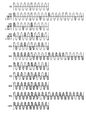
図2は、点灯パターンを模式的に示す図である。点灯パターン記憶部111は、各点灯デューティに対応付けられた点灯パターンを記憶している。ここで、点灯デューティとは、ハロゲンヒータ121の点灯比率である。本実施の形態においては、点灯デューティ10%間隔で10の点灯パターンが記憶されている。図2において、斜線で示す半波長がハロゲンヒータ121の点灯に相当する領域である。例えば、点灯デューティ30%においては、10半波長のうち所定の3半波長においてハロゲンヒータ121の点灯が設定されている。 FIG. 2 is a diagram schematically showing a lighting pattern. The lighting pattern storage unit 111 stores lighting patterns associated with each lighting duty. Here, the lighting duty is a lighting ratio of the halogen heater 121. In the present embodiment, 10 lighting patterns are stored at a lighting duty interval of 10%. In FIG. 2, the half wavelength indicated by diagonal lines is an area corresponding to the lighting of the halogen heater 121. For example, at a lighting duty of 30%, lighting of the halogen heater 121 is set at a predetermined three half wavelength out of ten half wavelengths.
本実施の形態にかかる点灯パターン記憶部111が記憶する点灯パターンは、いずれも10Hz前後の周波数帯域を回避するような点灯パターンである。すなわち、フリッカを回避するように全点灯または全消灯が割り当てられた点灯パターンである。なお、本実施の形態においては、点灯デューティ10%については、20半波長を制御周期とする半波制御パターンが記憶されている。 The lighting patterns stored in the lighting pattern storage unit 111 according to the present embodiment are all lighting patterns that avoid a frequency band around 10 Hz. That is, it is a lighting pattern in which all lighting or all lighting is assigned so as to avoid flicker. In the present embodiment, a half-wave control pattern having a control period of 20 half wavelengths is stored for a lighting duty of 10%.
図1の制御部113は、設定デューティ決定部114と、累積デューティ管理部115と、点灯制御部116とを有している。設定デューティ決定部114は、サーミスタ122により検出されたハロゲンヒータ121の表面温度と目標温度に基づいて設定デューティを決定する。
The
累積デューティ管理部115は、設定デューティ決定部114により設定デューティが決定されると、累積デューティ記憶部112に記憶されている累積デューティに、設定デューティ決定部114により新たに決定された設定デューティを加算する。そして、加算結果を新たな累積デューティとして累積デューティ記憶部112に記憶する。このように、累積デューティ記憶部112に記憶されている累積デューティは、設定デューティ決定部114により設定デューティが決定される度に更新される。なお、累積デューティ管理部115はまた適宜累積デューティ記憶部112に記憶されている累積デューティを0%または所定の値に更新する。
When the set duty is determined by the set
点灯制御部116は、設定デューティ決定部114により決定された設定デューティおよび累積デューティ記憶部112に記憶されている累積デューティから、ハロゲンヒータ121の点灯制御に利用する点灯デューティを決定し、点灯デューティに基づいて、ハロゲンヒータ121の点灯を制御する。
The
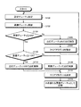
図3は、画像形成装置10によるヒータ制御処理を示すフローチャートである。なお、このヒータ制御処理は、ハロゲンヒータによる定着処理が行われない、待機状態において実行されるものとする。ヒータ制御処理においては、まず、設定デューティ決定部114は、設定デューティを決定する(ステップS100)。次に、累積デューティ管理部115は、累積デューティ記憶部112に記憶されている累積デューティを更新する(ステップS102)。具体的には、累積デューティ管理部115は、累積デューティ記憶部112に記憶されている累積デューティと、ステップS100において新たに決定された設定デューティとを加算する。そして、加算結果を新たな累積デューティとして累積デューティ記憶部112に記憶する。
FIG. 3 is a flowchart showing heater control processing by the
次に、点灯制御部116は、累積デューティ記憶部112に記憶されている累積デューティと予め設定された第1閾値とを比較する。なお、本実施の形態においては、第1閾値を40%とする。なお、第1閾値は比較的低い値であればよく、実施の形態に限定されるものではない。
Next, the
累積デューティ記憶部112に記憶されている累積デューティが第1閾値未満である場合には(ステップS104,No)、点灯制御部116は、点灯デューティを0%と決定し、この点灯デューティでハロゲンヒータ121の点灯を制御する(ステップS106)。すなわち、ハロゲンヒータ121を消灯させる。さらに、点灯制御部116は、累積デューティ記憶部112に記憶されているクリアフラグに「0」を設定し(ステップS108)、ステップS100に戻る。
When the accumulated duty stored in the accumulated
ここで、クリアフラグは、累積デューティを「0%」クリアするか否かを示す情報であり、「0」または「1」に設定される。具体的には、クリアフラグが「1」に設定されると、累積デューティ記憶部112の累積デューティはクリアされ、クリアフラグが「0」のときには、累積デューティのクリアは行われない。すなわち、ステップS108においては、累積デューティ記憶部112の累積デューティは、クリアされず、そのまま維持される。
Here, the clear flag is information indicating whether or not the accumulated duty is cleared to “0%”, and is set to “0” or “1”. Specifically, when the clear flag is set to “1”, the accumulated duty in the accumulated
待機状態においては、設定デューティ決定部114により決定された設定デューティと異なる点灯デューティでハロゲンヒータ121の点灯を制御しても、画像への影響がない。そこで、このように、待機状態において、設定デューティ決定部114により決定された設定デューティ加算後の累積デューティが閾値未満である場合には、点灯デューティを0%、すなわちハロゲンヒータ121を点灯しないこととする。このように、低デューティ時には、ハロゲンヒータ121の点灯を行わないこととするので、低デューティでの点灯に起因したフリッカ等の問題を解消することができる。
In the standby state, controlling the lighting of the halogen heater 121 with a lighting duty different from the set duty determined by the set
一方、ステップS104において、累積デューティ記憶部112に記憶されている累積デューティが第1閾値以上である場合には(ステップS104,Yes)、点灯制御部116は、さらに累積デューティと予め定められた第2閾値とを比較する。本実施の形態においては、第2閾値を110%とする。
On the other hand, when the cumulative duty stored in the cumulative
累積デューティが第2閾値以上である場合には(ステップS110,Yes)、点灯制御部116は、点灯デューティを100%と決定し、この点灯デューティでハロゲンヒータ121の点灯を制御する(ステップS112)。さらに、点灯制御部116は、累積デューティ記憶部112に記憶されているクリアフラグに「0」を設定する(ステップS114)。すなわち、累積デューティ記憶部112の累積デューティのクリアを行わない。次に、点灯制御部116は、累積デューティ記憶部112に記憶されている累積デューティから100%を減じた値を新たな累積デューティとして累積デューティ記憶部112に記憶し(ステップS116)、ステップS100に戻る。
When the accumulated duty is greater than or equal to the second threshold (step S110, Yes), the
このように、累積デューティが100%を超えた場合には、これまでに決定された設定デューティ分の点灯として、点灯デューティ100%でハロゲンヒータ121を点灯させる、すなわち全点灯させることとする。このように、高デューティで点灯させることにより、低デューティでの点灯に起因したフリッカ等の問題を解消しつつ、要求された設定デューティに応じた点灯を行うことができる。さらに、点灯分の100%を累積デューティから減ずることにより、次回以降の点灯デューティ決定において、未点灯分の累積デューティを加味することができる。 As described above, when the accumulated duty exceeds 100%, the halogen heater 121 is turned on at the lighting duty of 100%, that is, is fully turned on, as lighting for the set duty determined so far. As described above, by lighting at a high duty, it is possible to perform lighting according to a requested set duty while solving problems such as flicker caused by lighting at a low duty. Further, by subtracting 100% of the lighting amount from the accumulated duty, it is possible to take into account the accumulated duty of the unlit state in the next lighting duty determination.
ステップS110において、累積デューティが第2閾値未満である場合には(ステップS110,No)、点灯制御部116は、累積デューティ記憶部112に記憶されている累積デューティを点灯デューティとして、ハロゲンヒータ121の点灯を制御する(ステップS120)。次に、点灯制御部116は、累積デューティ記憶部112に記憶されているクリアフラグに「1」を設定する(ステップS122)。すなわち、累積デューティ記憶部112の累積デューティをクリアする。そして、点灯制御部116は、0%を新たな累積デューティとして累積デューティ記憶部112に記憶し(ステップS124)、ステップS100に戻る。
In step S110, when the accumulated duty is less than the second threshold (No in step S110), the
このように、累積デューティが40%以上でありかつ100%以下である場合には、累積デューティを点灯デューティとしてハロゲンヒータ121の点灯を制御することとした。これにより、このように、40%以上の点灯デューティでハロゲンヒータ121を点灯させることにより、低デューティでの点灯に起因したフリッカ等の問題を解消することができる。 As described above, when the cumulative duty is 40% or more and 100% or less, lighting of the halogen heater 121 is controlled with the cumulative duty as the lighting duty. Thus, by lighting the halogen heater 121 with a lighting duty of 40% or more in this way, problems such as flicker due to lighting with a low duty can be solved.
図4は、設定デューティ決定部114により決定された設定デューティの一例と、これに対応して設定される各種データを示す図である。設定デューティ決定部114は、10半波長の周期単位で点灯デューティを決定する。図4では、1周期目で10%、2周期目で10%、3周期目で20%、4周期目に70%の設定デューティを決定した例を示している。以下、図4に示す設定デューティが決定された場合のヒータ制御処理について具体的に説明する。
FIG. 4 is a diagram illustrating an example of the set duty determined by the set
まず、周期1において、設定デューティ10%が決定されると、累積デューティは、10%に更新される(ステップS102)。なお、累積デューティの初期値は0%とする。そして、累積デューティが40%未満であるため(ステップS104,No)、点灯デューティが0%に設定され(ステップS106)、クリアフラグに「0」が設定される(ステップS108)。
First, when 10% of the set duty is determined in
周期2においては、設定デューティが再度10%と決定され、累積デューティは、周期1において設定された10%に今回決定された設定デューティ10%が加算された値、すなわち20%に更新される(ステップS102)。累積デューティが40%未満であるため(ステップS104,No)、周期1の場合と同様に、点灯デューティが0%に設定され(ステップS106)、クリアフラグは「0」に設定される(ステップS108)。
In
周期3においては、設定デューティが20%と決定され、累積デューティは、周期2において設定された20%に今回決定された設定デューティ20%が加算された値、すなわち40%に更新される(ステップS102)。さらに、累積デューティが40%以上であり、かつ110%未満であるため(ステップS104,Yes、ステップS110,No)、点灯デューティに累積デューティ40%が設定される(ステップS120)。さらに、クリアフラグは「1」に設定され(ステップS122)、これにより、累積デューティは、0%に更新される(ステップS124)。
In
周期4においては、設定デューティが70%と決定される。このとき、累積デューティは周期3において0%にクリアされているため、累積デューティは70%に更新される(ステップS102)。累積デューティが40%以上であり、かつ110%未満であるため(ステップS104,Yes、ステップS110,No)、点灯デューティに累積デューティ70%が設定される(ステップS120)。さらに、クリアフラグに「1」が設定され(ステップS122)、これにより、累積デューティは、0%に更新される(ステップS124)。
In
図5は、図4に示す設定デューティが決定された場合の、ハロゲンヒータ121の点灯パターンを示す図である。このように、全消灯を除く低デューティを避けたハロゲンヒータ121の点灯制御を行うことができる。 FIG. 5 is a diagram showing a lighting pattern of the halogen heater 121 when the set duty shown in FIG. 4 is determined. In this way, it is possible to perform the lighting control of the halogen heater 121 while avoiding a low duty excluding all lights off.
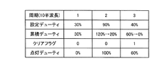
図6は、設定デューティ決定部114により決定された設定デューティの一例と、これに対応して設定される各種データを示す図である。図6では、1周期目で30%、2周期目で90%、3周期目で40%の設定デューティを決定した例を示している。以下、図6に示す設定デューティが決定された場合のヒータ制御処理について具体的に説明する。
FIG. 6 is a diagram illustrating an example of the set duty determined by the set
周期1において、設定デューティ30%と決定されると、初期値0%に今回決定された設定デューティ30%が加算され、累積デューティは30%に更新される(ステップS102)。累積デューティが40%未満であるため(ステップS104,No)、点灯デューティが0%に設定され(ステップS106)、クリアフラグは「0」に設定される(ステップS108)。
When it is determined that the set duty is 30% in the
周期2において、設定デューティ90%と決定されると、累積デューティ30%に今回決定された設定デューティ90%が加算され、累積デューティは120%に更新される(ステップS102)。累積デューティが110%以上であるため(ステップS104,Yes、ステップS110,Yes)、点灯デューティは100%に設定され(ステップS112)、クリアフラグに「0」が設定される(ステップS114)。さらに、累積デューティ120%から100%を減じた値、すなわち20%が新たな累積デューティに設定される(ステップS116)。
When it is determined that the set duty is 90% in the
周期3において、設定デューティ40%と決定されると、累積デューティ20%に今回決定された設定デューティ40%が加算され、累積デューティは60%に更新される(ステップS102)。累積デューティが40%以上であり、かつ110%未満であるため(ステップS104,Yes、ステップS110,No)、点灯デューティに累積デューティ60%が設定される(ステップS120)。さらに、クリアフラグに「1」が設定され(ステップS122)、これにより、累積デューティは、0%に更新される(ステップS124)。
If it is determined that the set duty is 40% in the
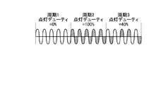
図7は、図6に示す設定デューティが決定された場合の、ハロゲンヒータ121の点灯パターンを示す図である。このように、累積デューティが110%以上となる場合においても、低デューティを避けたハロゲンヒータ121の点灯制御を行うことができる。 FIG. 7 is a diagram showing a lighting pattern of the halogen heater 121 when the set duty shown in FIG. 6 is determined. Thus, even when the cumulative duty is 110% or more, the lighting control of the halogen heater 121 can be performed while avoiding the low duty.
以上のように、本実施の形態にかかる画像形成装置10によれば、温度リップルが少なく、設定デューティと異なる値でハロゲンヒータ121を制御しても画像に影響が出ない待機状態においては、設定デューティとして低デューティが決定された場合には、フリッカ等の不都合が生じにくい、設定デューティと異なる点灯デューティでハロゲンヒータ121を制御することにより、フリッカを低減することができる。
As described above, according to the
第1の実施の形態の第1の変更例としては、ハロゲンヒータ121の定格が一定以上の場合に、実施の形態にかかるヒータ制御処理を行うこととしてもよい。ハロゲンヒータ121の定格が一定以上の場合には、突入電流増加による温度リップルが大きくなる。したがって、ハロゲンヒータ121の定格が例えば400Wなど所定の閾値以上である場合に、上述のヒータ制御処理を行うことが特に有効である。 As a first modification of the first embodiment, the heater control processing according to the embodiment may be performed when the rating of the halogen heater 121 is equal to or higher than a certain value. When the rating of the halogen heater 121 is equal to or higher than a certain level, a temperature ripple due to an increase in inrush current increases. Therefore, when the rating of the halogen heater 121 is equal to or higher than a predetermined threshold value such as 400 W, it is particularly effective to perform the heater control process described above.
また、第2の変更例としては、点灯パターン記憶部111は、画像形成装置10において利用されない点灯デューティ10%、20%および30%の点灯パターンは記憶しなくてもよい。
As a second modification, the lighting pattern storage unit 111 may not store lighting patterns of 10%, 20%, and 30% that are not used in the
(第2の実施の形態)
次に、第2の実施の形態にかかる画像形成装置10について説明する。第2の実施の形態にかかる画像形成装置10は、累積デューティが第2閾値以上である場合においても、累積デューティが第2閾値未満である場合と同様に、累積デューティをクリアする。この点で、第1の実施の形態にかかる画像形成装置10と異なっている。
(Second Embodiment)
Next, an
図8は、第2の実施の形態にかかる画像形成装置10によるヒータ制御処理を示すフローチャートである。第2の実施の形態にかかるヒータ制御処理においては、累積点灯デューティが110%以上である場合には(ステップS104,Yes、ステップS110,Yes)、点灯デューティ100%でハロゲンヒータ121の点灯を制御し(ステップS112)、さらにクリアフラグに「1」を設定し(ステップS122)、累積デューティをクリアし、0%を新たな累積デューティとして累積デューティ記憶部112に記憶し(ステップS124)、ステップS100に戻る。
FIG. 8 is a flowchart illustrating heater control processing by the
このように、第2の実施の形態にかかるヒータ制御処理においては、累積デューティが110%以上である場合においても、累積デューティをクリアするので、全点灯後、次回以降に決定された設定デューティを点灯デューティに反映させ易くすることができる。 As described above, in the heater control process according to the second embodiment, even when the accumulated duty is 110% or more, the accumulated duty is cleared. This can be easily reflected in the lighting duty.
図9は、設定デューティ決定部114により決定された設定デューティの一例と、これに対応して設定される各種データを示す図である。なお、設定デューティは、第1の実施の形態において図6を参照しつつ説明した設定デューティと同値である。
FIG. 9 is a diagram illustrating an example of the set duty determined by the set
以下、図9に示す設定デューティが決定された場合のヒータ制御処理について具体的に説明する。周期1において、設定デューティ30%と決定されると、初期値0%に今回決定された設定デューティ30%が加算され、累積デューティは30%に更新される(ステップS102)。累積デューティが40%未満であるため(ステップS104,No)、点灯デューティが0%に設定され(ステップS106)、クリアフラグは「0」に設定される(ステップS108)。
The heater control process when the set duty shown in FIG. 9 is determined will be specifically described below. When it is determined that the set duty is 30% in the
周期2において、設定デューティ90%と決定されると、累積デューティ30%に今回決定された設定デューティ90%が加算され、累積デューティは120%に更新される(ステップS102)。累積デューティが110%以上であるため(ステップS104,Yes、ステップS110,Yes)、点灯デューティは100%に設定される(ステップS112)。さらに、クリアフラグに「1」が設定され(ステップS122)、累積デューティは0%に更新される(ステップS124)。
When it is determined that the set duty is 90% in the
周期3において、設定デューティ40%と決定されると、累積デューティは今回決定された設定デューティ40%に更新される(ステップS102)。累積デューティが40%以上であり、かつ110%未満であるため(ステップS104,Yes、ステップS110,No)、点灯デューティに累積デューティ40%が設定される(ステップS120)。さらに、クリアフラグに「1」が設定され(ステップS122)、これにより、累積デューティは、0%に更新される(ステップS124)。
If it is determined that the set duty is 40% in
図10は、図9に示す設定デューティが決定された場合の、ハロゲンヒータ121の点灯パターンを示す図である。このように、第2の実施の形態におけるヒータ制御処理においても、低デューティを避けたハロゲンヒータ121の点灯制御を行うことができる。 FIG. 10 is a diagram showing a lighting pattern of the halogen heater 121 when the set duty shown in FIG. 9 is determined. Thus, also in the heater control processing in the second embodiment, it is possible to perform the lighting control of the halogen heater 121 while avoiding a low duty.
以上のように、本実施の形態にかかる画像形成装置10によれば、第1の実施の形態にかかる画像形成装置10と同様に、温度リップルが少なく、設定デューティと異なる値でハロゲンヒータ121を制御しても画像に影響が出ない待機状態においては、設定デューティとして低デューティが決定された場合には、フリッカ等の不都合が生じにくい、設定デューティと異なる点灯デューティでハロゲンヒータ121を制御することにより、フリッカを低減することができる。さらに、累積デューティが110%以上である場合においても、累積デューティをクリアすることにより、次回以降に決定された設定デューティを点灯デューティに反映させ易くすることができる。
As described above, according to the
なお、第2の実施の形態にかかる画像形成装置10のこれ以外の構成および処理は、第1の実施の形態にかかる画像形成装置10の構成および処理と同様である。
The other configuration and processing of the
本実施の形態の画像形成装置は、CPUなどの制御装置と、ROMやRAMなどの記憶装置と、HDD、CDドライブ装置などの外部記憶装置とを備えており、通常のコンピュータを利用したハードウェア構成となっている。 The image forming apparatus according to the present embodiment includes a control device such as a CPU, a storage device such as a ROM and a RAM, and an external storage device such as an HDD and a CD drive device, and hardware using a normal computer. It has a configuration.
本実施形態の画像形成装置で実行されるヒータ制御プログラムは、インストール可能な形式又は実行可能な形式のファイルでCD−ROM、フレキシブルディスク(FD)、CD−R、DVD(Digital Versatile Disk)等のコンピュータで読み取り可能な記録媒体に記録されて提供される。 The heater control program executed in the image forming apparatus according to the present embodiment is a file in an installable or executable format, such as a CD-ROM, a flexible disk (FD), a CD-R, a DVD (Digital Versatile Disk), or the like. The program is provided by being recorded on a computer-readable recording medium.
また、本実施形態の画像形成装置で実行されるヒータ制御プログラムを、インターネット等のネットワークに接続されたコンピュータ上に格納し、ネットワーク経由でダウンロードさせることにより提供するように構成しても良い。また、本実施形態の画像形成装置で実行されるヒータ制御プログラムをインターネット等のネットワーク経由で提供または配布するように構成しても良い。 The heater control program executed by the image forming apparatus according to the present embodiment may be stored on a computer connected to a network such as the Internet and provided by being downloaded via the network. The heater control program executed by the image forming apparatus according to the present embodiment may be provided or distributed via a network such as the Internet.
また、本実施形態のヒータ制御プログラムを、ROM等に予め組み込んで提供するように構成してもよい。 Further, the heater control program according to the present embodiment may be provided by being incorporated in advance in a ROM or the like.
本実施の形態の画像形成装置で実行されるヒータ制御プログラムは、上述した各部(点灯デューティ決定部、点灯パターン抽出部、一部点灯割当部、点灯制御部)を含むモジュール構成となっており、実際のハードウェアとしてはCPU(プロセッサ)が上記記憶媒体からヒータ制御プログラムを読み出して実行することにより上記各部が主記憶装置上にロードされ、各部が主記憶装置上に生成されるようになっている。 The heater control program executed in the image forming apparatus according to the present embodiment has a module configuration including the above-described units (lighting duty determination unit, lighting pattern extraction unit, partial lighting allocation unit, lighting control unit), As actual hardware, a CPU (processor) reads out and executes a heater control program from the storage medium, whereby each unit is loaded on the main storage device, and each unit is generated on the main storage device. Yes.
なお、上記実施の形態では、本発明の画像形成装置は、コピー機能、プリンタ機能、スキャナ機能およびファクシミリ機能のうち少なくとも2つの機能を有する複合機であってもよく、複写機、プリンタ、スキャナ装置、ファクシミリ装置等の画像形成装置であればいずれにも適用することができる。 In the above embodiment, the image forming apparatus of the present invention may be a multi-function machine having at least two functions among a copy function, a printer function, a scanner function, and a facsimile function. The present invention can be applied to any image forming apparatus such as a facsimile apparatus.
10 画像形成装置
100 メイン電源
101 AC電源
102 フィルタ
103 整流ダイオード
104 平滑コンデンサ
106 電磁リレー
107 スイッチ
108 ゼロクロス検知回路
110 制御基板
111 点灯パターン記憶部
112 累積デューティ記憶部
113 制御部
114 設定デューティ決定部
115 累積デューティ管理部
116 点灯制御部
120 定着ユニット
121 ハロゲンヒータ
122 サーミスタ
141 電源SW
142 ドアSW
143 TRI
DESCRIPTION OF
142 Door SW
143 TRI
Claims (8)
前記ヒータに交流電圧を印加する交流電源と、
前記加熱対象物の温度と目標温度に基づいて、前記ヒータの点灯比率を決定する点灯比率決定手段と、
所定の制御周期を単位とするパターンであって、フリッカを回避するように、前記制御周期内の前記交流電圧の半波長に全点灯または全消灯が割り当てられた点灯パターンを記憶する点灯パターン記憶手段と、
前記点灯比率決定手段によりこれまでに決定された点灯比率の累積値である累積比率を記憶する累積比率記憶手段と、
前記点灯比率決定手段により前記点灯比率が決定された場合に、前記累積比率記憶手段に記憶されている前記累積比率に新たに決定された前記点灯比率を加算した値を新たな前記累積比率として前記累積比率記憶手段に記憶する累積比率管理手段と、
前記加熱対象物による動作が行われていない待機状態であってかつ前記累積比率記憶手段に記憶されている前記累積比率が予め設定された第1閾値未満の場合に前記ヒータを消灯させ、前記待機状態であって、前記累積比率記憶手段に記憶されている前記累積比率が前記第1閾値よりも大きい第2閾値よりも大きい場合に前記ヒータを前記点灯比率100%で点灯させ、前記待機状態であって、前記累積比率記憶手段に記憶されている前記累積比率が前記第1閾値以上であってかつ前記第2閾値以下である場合に前記ヒータを前記累積比率に対応する前記点灯パターンで点灯させる点灯制御手段と
を備えたことを特徴とするヒータ制御装置。 Temperature detecting means for detecting the temperature of the heating object heated by the heater;
An AC power supply for applying an AC voltage to the heater;
A lighting ratio determining means for determining a lighting ratio of the heater based on the temperature of the heating object and a target temperature;
A lighting pattern storage means for storing a lighting pattern in which all lighting or all lighting is assigned to a half wavelength of the AC voltage in the control cycle so as to avoid flicker, the pattern being a unit of a predetermined control cycle When,
A cumulative ratio storage means for storing a cumulative ratio that is a cumulative value of the lighting ratio determined so far by the lighting ratio determination means;
When the lighting ratio is determined by the lighting ratio determining means, a value obtained by adding the newly determined lighting ratio to the cumulative ratio stored in the cumulative ratio storage means is used as the new cumulative ratio. A cumulative ratio management means stored in the cumulative ratio storage means;
When the operation by the heating object is not performed and the cumulative ratio stored in the cumulative ratio storage means is less than a preset first threshold, the heater is turned off and the standby is performed. The heater is turned on at the lighting ratio of 100% when the cumulative ratio stored in the cumulative ratio storage means is greater than a second threshold value that is greater than the first threshold value. When the cumulative ratio stored in the cumulative ratio storage means is not less than the first threshold and not more than the second threshold, the heater is turned on with the lighting pattern corresponding to the cumulative ratio. A heater control device comprising a lighting control means.
前記ヒータに交流電圧を印加する交流電源と、
前記加熱対象物の温度と目標温度に基づいて、前記ヒータの点灯比率を決定する点灯比率決定手段と、
所定の制御周期を単位とするパターンであって、フリッカを回避するように、前記制御周期内の前記交流電圧の半波長に全点灯または全消灯が割り当てられた点灯パターンを記憶する点灯パターン記憶手段と、
前記点灯比率決定手段によりこれまでに決定された点灯比率の累積値である累積比率を記憶する累積比率記憶手段と、
前記点灯比率決定手段により前記点灯比率が決定された場合に、前記累積比率記憶手段に記憶されている前記累積比率に新たに決定された前記点灯比率を加算した値を新たな前記累積比率として前記累積比率記憶手段に記憶する累積比率管理手段と、
前記加熱対象物による動作が行われていない待機状態であってかつ前記累積比率記憶手段に記憶されている前記累積比率が予め設定された第1閾値未満の場合に前記ヒータを消灯させ、前記待機状態であって、前記累積比率記憶手段に記憶されている前記累積比率が前記第1閾値よりも大きい第2閾値よりも大きい場合に前記ヒータを前記点灯比率100%で点灯させ、前記待機状態であって、前記累積比率記憶手段に記憶されている前記累積比率が前記第1閾値以上であってかつ前記第2閾値以下である場合に前記ヒータを前記累積比率に対応する前記点灯パターンで点灯させる点灯制御手段と
を備えたことを特徴とする画像形成装置。 Temperature detecting means for detecting the temperature of the heating object heated by the heater;
An AC power supply for applying an AC voltage to the heater;
A lighting ratio determining means for determining a lighting ratio of the heater based on the temperature of the heating object and a target temperature;
A lighting pattern storage means for storing a lighting pattern in which all lighting or all lighting is assigned to a half wavelength of the AC voltage in the control cycle so as to avoid flicker, the pattern being a unit of a predetermined control cycle When,
A cumulative ratio storage means for storing a cumulative ratio that is a cumulative value of the lighting ratio determined so far by the lighting ratio determination means;
When the lighting ratio is determined by the lighting ratio determining means, a value obtained by adding the newly determined lighting ratio to the cumulative ratio stored in the cumulative ratio storage means is used as the new cumulative ratio. A cumulative ratio management means stored in the cumulative ratio storage means;
When the operation by the heating object is not performed and the cumulative ratio stored in the cumulative ratio storage means is less than a preset first threshold, the heater is turned off and the standby is performed. The heater is turned on at the lighting ratio of 100% when the cumulative ratio stored in the cumulative ratio storage means is greater than a second threshold value that is greater than the first threshold value. When the cumulative ratio stored in the cumulative ratio storage means is not less than the first threshold and not more than the second threshold, the heater is turned on with the lighting pattern corresponding to the cumulative ratio. An image forming apparatus comprising a lighting control unit.
前記ヒータ制御装置は、
所定の制御周期を単位とするパターンであって、フリッカを回避するように、前記制御周期内の前記交流電圧の半波長に全点灯または全消灯が割り当てられた点灯パターンを記憶する点灯パターン記憶手段と、
前記ヒータの点灯比率の累積値である累積比率を記憶する累積比率記憶手段と
を備え、
前記加熱対象物の温度と目標温度に基づいて、前記ヒータの点灯比率を決定する点灯比率決定ステップと、
前記点灯比率決定ステップで、これまでに決定された点灯比率の累積値である累積比率を前記累積比率記憶手段に記憶する記憶ステップと、
前記点灯比率決定ステップで前記点灯比率が決定された場合に、前記累積比率記憶手段に記憶されている前記累積比率に新たに決定された前記点灯比率を加算した値を新たな前記累積比率として前記累積比率記憶手段に記憶する累積比率管理ステップと、
前記加熱対象物による動作が行われていない待機状態であってかつ前記累積比率記憶手段に記憶されている前記累積比率が予め設定された第1閾値未満の場合に前記ヒータを消灯させ、前記待機状態であって、前記累積比率記憶手段に記憶されている前記累積比率が前記第1閾値よりも大きい第2閾値よりも大きい場合に前記ヒータを前記点灯比率100%で点灯させ、前記待機状態であって、前記累積比率記憶手段に記憶されている前記累積比率が前記第1閾値以上であってかつ前記第2閾値以下である場合に前記ヒータを前記累積比率に対応する前記点灯パターンで点灯させる点灯制御ステップと
を有することを特徴とするヒータ制御方法。 A heater control method executed by a heater control device,
The heater control device
A lighting pattern storage means for storing a lighting pattern in which all lighting or all lighting is assigned to a half wavelength of the AC voltage in the control cycle so as to avoid flicker, the pattern being a unit of a predetermined control cycle When,
A cumulative ratio storage means for storing a cumulative ratio that is a cumulative value of the lighting ratio of the heater;
A lighting ratio determination step for determining a lighting ratio of the heater based on the temperature of the heating object and a target temperature;
A storage step of storing, in the cumulative ratio storage means, a cumulative ratio that is a cumulative value of the lighting ratio determined so far in the lighting ratio determination step;
When the lighting ratio is determined in the lighting ratio determination step, a value obtained by adding the newly determined lighting ratio to the cumulative ratio stored in the cumulative ratio storage means is used as the new cumulative ratio. A cumulative ratio management step stored in the cumulative ratio storage means;
When the operation by the heating object is not performed and the cumulative ratio stored in the cumulative ratio storage means is less than a preset first threshold, the heater is turned off and the standby is performed. The heater is turned on at the lighting ratio of 100% when the cumulative ratio stored in the cumulative ratio storage means is greater than a second threshold value that is greater than the first threshold value. When the cumulative ratio stored in the cumulative ratio storage means is not less than the first threshold and not more than the second threshold, the heater is turned on with the lighting pattern corresponding to the cumulative ratio. A heater control method comprising: a lighting control step.
前記コンピュータは、
所定の制御周期を単位とするパターンであって、フリッカを回避するように、前記制御周期内の前記交流電圧の半波長に全点灯または全消灯が割り当てられた点灯パターンを記憶する点灯パターン記憶手段と、
前記ヒータの点灯比率の累積値である累積比率を記憶する累積比率記憶手段と
を備え、
前記加熱対象物の温度と目標温度に基づいて、前記ヒータの点灯比率を決定する点灯比率決定ステップと、
前記点灯比率決定ステップで、これまでに決定された点灯比率の累積値である累積比率を前記累積比率記憶手段に記憶する記憶ステップと、
前記点灯比率決定ステップで前記点灯比率が決定された場合に、前記累積比率記憶手段に記憶されている前記累積比率に新たに決定された前記点灯比率を加算した値を新たな前記累積比率として前記累積比率記憶手段に記憶する累積比率管理ステップと、
前記加熱対象物による動作が行われていない待機状態であってかつ前記累積比率記憶手段に記憶されている前記累積比率が予め設定された第1閾値未満の場合に前記ヒータを消灯させ、前記待機状態であって、前記累積比率記憶手段に記憶されている前記累積比率が前記第1閾値よりも大きい第2閾値よりも大きい場合に前記ヒータを前記点灯比率100%で点灯させ、前記待機状態であって、前記累積比率記憶手段に記憶されている前記累積比率が前記第1閾値以上であってかつ前記第2閾値以下である場合に前記ヒータを前記累積比率に対応する前記点灯パターンで点灯させる点灯制御ステップと
を前記コンピュータに実行させるためのプログラム。 A program for causing a computer to execute heater control,
The computer
A lighting pattern storage means for storing a lighting pattern in which all lighting or all lighting is assigned to a half wavelength of the AC voltage in the control cycle so as to avoid flicker, the pattern being a unit of a predetermined control cycle When,
A cumulative ratio storage means for storing a cumulative ratio that is a cumulative value of the lighting ratio of the heater;
A lighting ratio determination step for determining a lighting ratio of the heater based on the temperature of the heating object and a target temperature;
A storage step of storing, in the cumulative ratio storage means, a cumulative ratio that is a cumulative value of the lighting ratio determined so far in the lighting ratio determination step;
When the lighting ratio is determined in the lighting ratio determination step, a value obtained by adding the newly determined lighting ratio to the cumulative ratio stored in the cumulative ratio storage means is used as the new cumulative ratio. A cumulative ratio management step stored in the cumulative ratio storage means;
When the operation by the heating object is not performed and the cumulative ratio stored in the cumulative ratio storage means is less than a preset first threshold, the heater is turned off and the standby is performed. The heater is turned on at the lighting ratio of 100% when the cumulative ratio stored in the cumulative ratio storage means is greater than a second threshold value that is greater than the first threshold value. When the cumulative ratio stored in the cumulative ratio storage means is not less than the first threshold and not more than the second threshold, the heater is turned on with the lighting pattern corresponding to the cumulative ratio. A program for causing the computer to execute a lighting control step.
Priority Applications (1)
| Application Number | Priority Date | Filing Date | Title |
|---|---|---|---|
| JP2009240887A JP5397151B2 (en) | 2009-10-19 | 2009-10-19 | HEATER CONTROL DEVICE, IMAGE FORMING DEVICE, HEATER CONTROL METHOD, AND PROGRAM |
Applications Claiming Priority (1)
| Application Number | Priority Date | Filing Date | Title |
|---|---|---|---|
| JP2009240887A JP5397151B2 (en) | 2009-10-19 | 2009-10-19 | HEATER CONTROL DEVICE, IMAGE FORMING DEVICE, HEATER CONTROL METHOD, AND PROGRAM |
Publications (2)
| Publication Number | Publication Date |
|---|---|
| JP2011086592A JP2011086592A (en) | 2011-04-28 |
| JP5397151B2 true JP5397151B2 (en) | 2014-01-22 |
Family
ID=44079383
Family Applications (1)
| Application Number | Title | Priority Date | Filing Date |
|---|---|---|---|
| JP2009240887A Expired - Fee Related JP5397151B2 (en) | 2009-10-19 | 2009-10-19 | HEATER CONTROL DEVICE, IMAGE FORMING DEVICE, HEATER CONTROL METHOD, AND PROGRAM |
Country Status (1)
| Country | Link |
|---|---|
| JP (1) | JP5397151B2 (en) |
Families Citing this family (1)
| Publication number | Priority date | Publication date | Assignee | Title |
|---|---|---|---|---|
| JP5041016B2 (en) * | 2010-03-01 | 2012-10-03 | 東京エレクトロン株式会社 | Heat treatment apparatus, heat treatment method and storage medium |
Family Cites Families (3)
| Publication number | Priority date | Publication date | Assignee | Title |
|---|---|---|---|---|
| JP3022051B2 (en) * | 1993-04-27 | 2000-03-15 | 理化工業株式会社 | AC power control device |
| JP2004191710A (en) * | 2002-12-12 | 2004-07-08 | Kyocera Mita Corp | Fixation device and image forming device equipped with the same |
| JP2004212585A (en) * | 2002-12-27 | 2004-07-29 | Kyocera Mita Corp | Temperature control method for fixing device and the device |
-
2009
- 2009-10-19 JP JP2009240887A patent/JP5397151B2/en not_active Expired - Fee Related
Also Published As
| Publication number | Publication date |
|---|---|
| JP2011086592A (en) | 2011-04-28 |
Similar Documents
| Publication | Publication Date | Title |
|---|---|---|
| JP5471618B2 (en) | HEATER CONTROL DEVICE, IMAGE FORMING DEVICE, HEATER CONTROL METHOD, AND PROGRAM | |
| US8530800B2 (en) | Heater control device, image forming apparatus, and computer program product | |
| EP2278417B1 (en) | Image forming apparatus and heater control method | |
| JP5516097B2 (en) | Image forming apparatus, heater control method, and program | |
| EP1843215B1 (en) | System and Method of Controlling Temperature of Fixing Unit | |
| KR101248910B1 (en) | Switching mode power supply and image forming device having the same and method of driving thereof | |
| JP2004294554A (en) | Image forming apparatus | |
| JP5321380B2 (en) | HEATER CONTROL DEVICE, IMAGE FORMING DEVICE, AND PROGRAM | |
| JP5397151B2 (en) | HEATER CONTROL DEVICE, IMAGE FORMING DEVICE, HEATER CONTROL METHOD, AND PROGRAM | |
| KR101323740B1 (en) | Apparatus for controlling of fixing unit and image forming apparatus having the same | |
| JP5573481B2 (en) | Heater control apparatus, image forming apparatus, heater control method, and computer-executable program | |
| JP5614188B2 (en) | HEATER CONTROL DEVICE, IMAGE FORMING DEVICE, AND PROGRAM | |
| JP5375477B2 (en) | HEATER CONTROL DEVICE, IMAGE FORMING DEVICE, HEATER CONTROL METHOD, AND HEATER CONTROL PROGRAM | |
| JP2012252405A (en) | Power-supply device and image-forming device equipped with the same | |
| JP5446645B2 (en) | HEATER CONTROL DEVICE, HEATER CONTROL METHOD, AND PROGRAM | |
| US8266455B2 (en) | Apparatus and method for controlling power of fixing unit | |
| JP2002182521A (en) | Fixing heater controller | |
| JP2006304534A (en) | Switching power supply and imaging apparatus equipped with the same | |
| JP5625496B2 (en) | Induction heating device | |
| JP2013167813A (en) | Image forming apparatus and energization control method for heater | |
| JP5877302B2 (en) | Induction heating device | |
| JPH09197896A (en) | Image forming device | |
| JP6204342B2 (en) | Power supply apparatus and image forming apparatus | |
| JP5167695B2 (en) | Image forming apparatus | |
| JP2009273020A (en) | Image processing apparatus, power supply control method, power supply control program and recording medium |
Legal Events
| Date | Code | Title | Description |
|---|---|---|---|
| A621 | Written request for application examination |
Free format text: JAPANESE INTERMEDIATE CODE: A621 Effective date: 20120807 |
|
| TRDD | Decision of grant or rejection written | ||
| A01 | Written decision to grant a patent or to grant a registration (utility model) |
Free format text: JAPANESE INTERMEDIATE CODE: A01 Effective date: 20130924 |
|
| A61 | First payment of annual fees (during grant procedure) |
Free format text: JAPANESE INTERMEDIATE CODE: A61 Effective date: 20131007 |
|
| R151 | Written notification of patent or utility model registration |
Ref document number: 5397151 Country of ref document: JP Free format text: JAPANESE INTERMEDIATE CODE: R151 |
|
| LAPS | Cancellation because of no payment of annual fees |