JP5321380B2 - HEATER CONTROL DEVICE, IMAGE FORMING DEVICE, AND PROGRAM - Google Patents
HEATER CONTROL DEVICE, IMAGE FORMING DEVICE, AND PROGRAM Download PDFInfo
- Publication number
- JP5321380B2 JP5321380B2 JP2009212610A JP2009212610A JP5321380B2 JP 5321380 B2 JP5321380 B2 JP 5321380B2 JP 2009212610 A JP2009212610 A JP 2009212610A JP 2009212610 A JP2009212610 A JP 2009212610A JP 5321380 B2 JP5321380 B2 JP 5321380B2
- Authority
- JP
- Japan
- Prior art keywords
- lighting
- pattern
- partial
- heater
- assigned
- Prior art date
- Legal status (The legal status is an assumption and is not a legal conclusion. Google has not performed a legal analysis and makes no representation as to the accuracy of the status listed.)
- Active
Links
Images


Landscapes
- Fixing For Electrophotography (AREA)
Description
本発明は、ヒータの点灯を制御するヒータ制御装置、画像形成装置およびプログラムに関する。 The present invention relates to a heater control device that controls lighting of a heater, an image forming apparatus, and a program.
電子写真方式の画像形成装置に用いられる定着ヒータには、ハロゲンヒータが広く用いられている。ハロゲンヒータは、ヒータの中でも特に低温時に突入電流を発生しやすい特性があり、また定常的な消費電流も大きい。このためヒータ点灯タイミングと同期して商用電源の電圧降下を発生し蛍光灯などの照明器具がちらつく原因となっている。 A halogen heater is widely used as a fixing heater used in an electrophotographic image forming apparatus. The halogen heater has a characteristic that an inrush current is likely to be generated particularly at a low temperature among heaters, and a steady consumption current is large. For this reason, a voltage drop of the commercial power supply is generated in synchronization with the heater lighting timing, causing a lighting fixture such as a fluorescent lamp to flicker.
これに対し、人間の目に敏感に感じるとされるちらつきの周波数帯(8.8〜10Hz)に対し、ヒータの点灯制御が約10Hz帯域のスイッチングにならないように、または周波数成分が極力小さくなるように、ちらつきの対象となる周波数に近い10半波長(100ms)周期の半波サイクル単位で点灯パターンを制御する技術が知られている(例えば、特許文献1参照)。これにより、フリッカ、高調波電流および雑音端子電圧規制の問題に対応している。 On the other hand, with respect to the flicker frequency band (8.8 to 10 Hz) that is considered to be sensitive to human eyes, the lighting component of the heater is not switched to about 10 Hz band, or the frequency component is minimized. As described above, a technique for controlling the lighting pattern in units of half-wave cycles having a period of 10 half wavelengths (100 ms) close to the frequency to be flickered is known (for example, see Patent Document 1). This addresses the problem of flicker, harmonic current and noise terminal voltage regulation.
さらに、突入電流の抑制を目的として、上述の高周波点灯パターンの直前に半波長の一部のみヒータをオンし、徐々にオン時間を長くする位相制御(ソフトスタート)を導入する技術が提案されている(例えば、特許文献2参照)。 In addition, for the purpose of suppressing inrush current, a technology has been proposed that introduces phase control (soft start) that turns on the heater only for a part of the half wavelength immediately before the above-described high-frequency lighting pattern and gradually increases the on-time. (For example, refer to Patent Document 2).
しかしながら、10半波長周期の半波サイクル単位での点灯パターンのヒータ制御においては、点灯デューティ(点灯比率)によるフリッカレベルの差が生じており、低デューティ(10〜30%付近)では、中デューティ(40〜60%付近)と比較し周波数特性が劣っておりフリッカレベルが悪い傾向にあることがわかっている。 However, in the heater control of the lighting pattern in a half wave cycle unit of 10 half wavelength cycles, a difference in flicker level occurs due to the lighting duty (lighting ratio), and at a low duty (around 10 to 30%), a medium duty is generated. It is known that the frequency characteristics are inferior compared to (around 40 to 60%) and the flicker level tends to be poor.
このため、本点灯中のごく短時間(数10msec)の消灯期間に起因する突入電流を抑制することができず、消灯期間が数半波以上続く低デューティにおいては、フリッカレベルの改善があまり見込まれないという問題があった。さらに、低デューティにおいては点灯回数が少なく、周波数成分の改善(高周波化)も行えないという問題があった。また、本点灯中に上述の位相制御を利用した場合には、高調波電流、雑音端子電圧の特性を極端に悪化させてしまうという問題があった。 For this reason, the inrush current caused by the extinguishing period for a very short time (several tens of milliseconds) during the main lighting cannot be suppressed, and the flicker level is not expected to be improved much at low duty where the extinguishing period lasts several half waves or more. There was a problem of not being able to. Further, there is a problem that the number of times of lighting is small at a low duty and the frequency component cannot be improved (high frequency). Further, when the above-described phase control is used during the main lighting, there is a problem that the characteristics of the harmonic current and the noise terminal voltage are extremely deteriorated.
本発明は、上記に鑑みてなされたものであって、点灯比率が低い場合においても、高調波電流、雑音端子電圧のレベル悪化を抑制しつつ、フリッカレベルを改善することのできるヒータ制御装置、画像形成装置およびプログラムを提供することを目的とする。 The present invention has been made in view of the above, and even when the lighting ratio is low, the heater control device capable of improving the flicker level while suppressing the level deterioration of the harmonic current and the noise terminal voltage, An object is to provide an image forming apparatus and a program.
上述した課題を解決し、目的を達成するために、本発明は、ヒータ制御装置であって、ヒータにより加熱される加熱対象物の温度を検出する温度検出手段と、前記ヒータに交流電圧を印加する交流電源と、前記加熱対象物の温度と目標温度に基づいて、前記ヒータの点灯比率を決定する点灯比率決定手段と、所定の制御周期を単位とするパターンであって、フリッカを回避するように、前記制御周期内の前記交流電圧の半波長に全点灯または全消灯が割り当てられた点灯パターンを記憶する点灯パターン記憶手段と、決定された前記点灯比率が閾値以下である場合に、前記点灯パターン記憶手段において、前記点灯比率決定手段により決定された前記点灯比率よりも高い点灯比率に対応付けられている前記点灯パターンを抽出する点灯パターン抽出手段と、抽出された前記点灯パターンにおいて全点灯が割り当てられている半波長に対し、前記全点灯にかえて一部点灯を割り当てる一部点灯割当手段と、一部点灯が割り当てられた前記点灯パターンに基づいて、前記ヒータの点灯を制御する点灯制御手段とを備えたことを特徴とする。 In order to solve the above-mentioned problems and achieve the object, the present invention is a heater control device, which is a temperature detecting means for detecting the temperature of a heating object heated by the heater, and an AC voltage is applied to the heater. An alternating current power supply, a lighting ratio determining means for determining a lighting ratio of the heater based on the temperature and target temperature of the heating object, and a pattern with a predetermined control cycle as a unit so as to avoid flicker A lighting pattern storage means for storing a lighting pattern in which full lighting or full lighting is assigned to a half wavelength of the AC voltage within the control cycle, and the lighting when the determined lighting ratio is equal to or less than a threshold value. In a pattern storage means, a lighting pattern for extracting the lighting pattern associated with a lighting ratio higher than the lighting ratio determined by the lighting ratio determining means Extraction means, partial lighting assignment means for assigning partial lighting instead of full lighting for the half wavelength to which full lighting is assigned in the extracted lighting pattern, and lighting for which partial lighting is assigned And a lighting control means for controlling lighting of the heater based on the pattern.
また、本発明の他の形態は、画像形成装置であって、ヒータにより加熱される加熱対象物の温度を検出する温度検出手段と、前記ヒータに交流電圧を印加する交流電源と、前記加熱対象物の温度と目標温度に基づいて、前記ヒータの点灯比率を決定する点灯比率決定手段と、所定の制御周期を単位とするパターンであって、フリッカを回避するように、前記制御周期内の前記交流電圧の半波長に全点灯または全消灯が割り当てられた点灯パターンを記憶する点灯パターン記憶手段と、決定された前記点灯比率が閾値以下である場合に、前記点灯パターン記憶手段において、前記点灯比率決定手段により決定された前記点灯比率よりも高い点灯比率に対応付けられている前記点灯パターンを抽出する点灯パターン抽出手段と、抽出された前記点灯パターンにおいて全点灯が割り当てられている半波長に対し、前記全点灯にかえて一部点灯を割り当てる一部点灯割当手段と、一部点灯が割り当てられた前記点灯パターンに基づいて、前記ヒータの点灯を制御する点灯制御手段とを備えたことを特徴とする。 According to another aspect of the present invention, there is provided an image forming apparatus including a temperature detecting unit that detects a temperature of an object to be heated by a heater, an AC power source that applies an AC voltage to the heater, and the heating object. A lighting ratio determining means for determining a lighting ratio of the heater based on the temperature of the object and a target temperature; and a pattern having a predetermined control period as a unit, and the flicker within the control period so as to avoid flicker In the lighting pattern storage means for storing a lighting pattern in which full lighting or full lighting is assigned to a half wavelength of the AC voltage, and when the determined lighting ratio is equal to or less than a threshold value, the lighting ratio in the lighting pattern storage means Lighting pattern extraction means for extracting the lighting pattern associated with a lighting ratio higher than the lighting ratio determined by the determination means, and the extracted point On the half wavelength to which full lighting is assigned in the pattern, partial lighting assignment means for assigning partial lighting instead of full lighting, and lighting of the heater based on the lighting pattern to which partial lighting is assigned And a lighting control means for controlling the lighting.
また、本発明の他の形態は、ヒータ制御処理をコンピュータに実行させるためのプログラムであって、前記コンピュータは、所定の制御周期を単位とするパターンであって、フリッカを回避するように、前記制御周期内のヒータに印加される交流電圧の半波長に全点灯または全消灯が割り当てられた点灯パターンを記憶する点灯パターン記憶手段を備え、前記コンピュータに、前記加熱対象物の温度と目標温度に基づいて、前記ヒータの点灯比率を決定する点灯比率決定ステップと、決定された前記点灯比率が閾値以下である場合に、前記点灯パターン記憶手段において、前記点灯比率決定ステップで決定された前記点灯比率よりも高い点灯比率に対応付けられている前記点灯パターンを抽出する点灯パターン抽出ステップと、抽出された前記点灯パターンにおいて全点灯が割り当てられている半波長に対し、前記全点灯にかえて一部点灯を割り当てる一部点灯割当ステップと、一部点灯が割り当てられた前記点灯パターンに基づいて、前記ヒータの点灯を制御する点灯制御ステップとを前記コンピュータに実行させるためのプログラムである。 Further, another aspect of the present invention is a program for causing a computer to execute a heater control process, wherein the computer is a pattern having a predetermined control cycle as a unit, and avoids flicker. A lighting pattern storage means for storing a lighting pattern in which full lighting or full lighting is assigned to a half wavelength of an AC voltage applied to a heater within a control cycle is provided, and the computer has a temperature and a target temperature of the heating object. A lighting ratio determining step for determining a lighting ratio of the heater based on the lighting ratio determined in the lighting ratio determining step in the lighting pattern storage means when the determined lighting ratio is equal to or less than a threshold value; A lighting pattern extraction step for extracting the lighting pattern associated with a higher lighting ratio, and before extraction A partial lighting assignment step in which partial lighting is assigned instead of the full lighting for a half wavelength to which full lighting is assigned in the lighting pattern, and based on the lighting pattern in which partial lighting is assigned, A program for causing the computer to execute a lighting control step for controlling lighting.
本発明によれば、点灯比率が低い場合においても、高調波電流、雑音端子電圧のレベル低下を抑制しつつ、フリッカレベルを改善することのできるという効果を奏する。 According to the present invention, even when the lighting ratio is low, there is an effect that the flicker level can be improved while suppressing a decrease in the levels of the harmonic current and the noise terminal voltage.
以下に添付図面を参照して、この発明にかかるヒータ制御装置、画像形成装置およびプログラムの一実施の形態を詳細に説明する。 Exemplary embodiments of a heater control device, an image forming apparatus, and a program according to the present invention will be explained below in detail with reference to the accompanying drawings.
図1は、本発明の実施の形態にかかる画像形成装置10の全体構成を示すブロック図である。画像形成装置10は、画像形成装置10に設けられた定着ユニット等のヒータを制御するヒータ制御装置を含んでいる。具体的には、画像形成装置10は、メイン電源100と、制御基板110とを主に備えている。さらに、画像形成装置10は、さらに、定着ユニット120と、電源SW141と、ドアSW142と、トライアック(TRI)143とを備えている。
FIG. 1 is a block diagram showing an overall configuration of an
制御基板110は、画像形成装置10全体を制御する。制御基板110は、不図示のCPU、RAM、ROM、NVRAM、ASIC(Application Specific Integrated Circuit)、入出力インターフェイスがバスを介して接続されたコンピュータとして実装される。
The
制御基板110は、メイン電源100と、定着ユニット120の間に設けられたTRI143や電磁リレー106のオン/オフを制御することにより、定着ユニット120のハロゲンヒータ121の温度制御やオン/オフの制御を行う。なお、ハロゲンヒータ121にかえて、セラミックヒータなど他のヒータを用いてもよい。
The
定着ユニット120のハロゲンヒータ121の近傍に配置されたサーミスタ122は、ハロゲンヒータ121の表面温度を検知する。制御基板110は、サーミスタ122が検知した表面温度をA/D変換して、ハロゲンヒータ121の表面温度を検知する。制御基板110は、この表面温度が安定するようTRI143や電磁リレー106のオン/オフを制御する。
A thermistor 122 disposed in the vicinity of the halogen heater 121 of the
画像形成装置10の電源SW141がオンになると、AC電源101から供給された電流はフィルタ102でノイズ除去された後、整流ダイオード103及び平滑コンデンサ104で平滑化され、DDC(Digital Down Conveter)105に供給される。DDC105は、スイッチング方式のDC−DCコンバータであり、定電圧Vccを制御基板110に、24Vを電磁リレー106に供給する。
When the
電磁リレー106は、画像形成装置10のドアSW142がオンになるとスイッチ107をオンにすると共に、制御基板110を介して、定着ユニット120をオフにすることができる。すなわち、定着ユニット120の安全装置となる。
The
ゼロクロス検知回路108は、AC電源101のゼロクロス点を検出する。制御基板110は、このゼロクロス点に応じてTRI143をオン/オフする。スイッチ107がオンの場合、ゼロクロス検知回路108に供給される交流電流は、半波長毎に電圧がゼロ近くになる。このため、ゼロクロス検知回路108のトランジスタがオン電圧を保持できなくなる。ゼロクロス検知回路108は、このトランジスタの状態を検知してゼロクロス信号を制御基板110に出力する。
The zero
制御基板110は、点灯パターン記憶部111と、制御部112とを有している。制御部112は、交流電圧の半波長を1単位として、ハロゲンヒータ121への通電のオンオフを制御する間引き制御を行う。制御部112はまた、半波長の一部のみオンとする位相制御と間引き位相制御とを組み合わせた間引き位相制御を行う。なお、間引き位相制御については後述する。制御部112は、具体的には、点灯パターン記憶部111に記憶されている点灯パターンに従いハロゲンヒータ121の点灯を制御する。
The
点灯パターン記憶部111は、点灯パターンを記憶している。点灯パターンは、制御周期単位のハロゲンヒータ121の点灯パターンである。制御周期とは、制御基板110が制御するAC電源101の電圧周期であり、予め定められた長さの周期である。本実施の形態においては、制御周期を10半波長とする。これに対応し、点灯パターン記憶部111に記憶されている点灯パターンは、10半波長を単位として設定されている。
The lighting
図2は、点灯パターンを模式的に示す図である。点灯パターン記憶部111は、各点灯デューティに対応付けられた点灯パターンを記憶している。ここで、点灯デューティとは、ハロゲンヒータ121の点灯比率である。本実施の形態においては、点灯デューティ10%間隔で10の点灯パターンが記憶されている。図2において、斜線で示す半波長がハロゲンヒータ121の点灯に相当する領域である。例えば、点灯デューティ30%においては、10半波長のうち所定の3半波長においてハロゲンヒータ121の点灯が設定されている。このように、点灯パターン記憶部111に記憶されている点灯パターンは、ハロゲンヒータ121の点灯期間を半波長単位で間引く間引きパターンである。この間引きパターンによるハロゲンヒータ121の点灯制御を間引き制御と称する。
FIG. 2 is a diagram schematically showing a lighting pattern. The lighting
本実施の形態にかかる点灯パターン記憶部111が記憶する点灯パターンは、いずれも10Hz前後の周波数帯域を回避するような点灯パターンである。すなわち、フリッカを回避するように全点灯または全消灯が割り当てられた点灯パターンである。なお、本実施の形態においては、点灯デューティ10%については、20半波長を制御周期とする半波制御パターンが記憶されている。
The lighting patterns stored in the lighting
図1の制御部112は、点灯デューティ決定部113と、点灯パターン抽出部114と、一部点灯割当部115と、点灯制御部116とを有している。点灯デューティ決定部113は、サーミスタ122により検出されたハロゲンヒータ121の表面温度と目標温度に基づいて点灯デューティを決定する。
The
点灯パターン抽出部114は、点灯デューティ決定部113により決定された点灯デューティが予め設定された閾値以下である場合には、点灯デューティ決定部113により決定された点灯デューティよりも大きい点灯デューティに対応付けられている点灯パターンを点灯パターン記憶部111から抽出する。本実施の形態においては、閾値を30%とする。なお、閾値は、任意の値であればよく、実施の形態に限定されるものではない。
When the lighting duty determined by the lighting duty determination unit 113 is equal to or less than a preset threshold, the lighting
点灯デューティが閾値未満である場合に抽出される点灯パターンは予め設定されているものとする。本実施の形態においては、点灯デューティが10%と決定された場合には、周波数特性に優れている40%の点灯パターンを抽出するよう設定されているものとする。ただし、抽出される点灯パターンは40%に限定されるものではなく、閾値以上の他の点灯デューティの点灯パターンであってもよい。 It is assumed that the lighting pattern that is extracted when the lighting duty is less than the threshold is set in advance. In this embodiment, when the lighting duty is determined to be 10%, it is assumed that 40% lighting patterns having excellent frequency characteristics are set to be extracted. However, the lighting pattern to be extracted is not limited to 40%, and may be a lighting pattern having a lighting duty other than the threshold.
一方、点灯デューティ決定部113により決定された点灯デューティが閾値よりも大きい場合には、点灯パターン抽出部114は、点灯デューティ決定部113により決定された点灯デューティに対応付けられている点灯パターンを抽出する。
On the other hand, when the lighting duty determined by the lighting duty determination unit 113 is larger than the threshold value, the lighting
一部点灯割当部115は、点灯パターン抽出部114が点灯デューティ決定部113により決定された点灯デューティよりも大きい点灯デューティに対応付けられている点灯パターンを点灯パターン記憶部111から抽出した場合に、点灯パターン抽出部114により抽出された点灯パターンにおいて全点灯が割り当てられている半波長に対し、全点灯に替えて一部点灯を割り当てる。ここで、一部点灯とは、半波長のうち一部の期間のみハロゲンヒータ121を点灯させるものである。すなわち、一部点灯は、交流電圧の位相を変化させる制御である。
When the lighting
一部点灯割当部115により得られた点灯パターンは、間引きパターンに一部点灯が割り当てられたパターンであり、この点灯パターンによるハロゲンヒータ121の点灯制御を間引き位相制御と称する。 The lighting pattern obtained by the partial lighting assignment unit 115 is a pattern in which partial lighting is assigned to the thinning pattern, and lighting control of the halogen heater 121 by this lighting pattern is referred to as thinning phase control.
点灯制御部116は、点灯パターン抽出部114により抽出された点灯パターンまたは一部点灯割当部115により一部点灯が割り当てられた点灯パターンに基づいて、ハロゲンヒータ121の点灯を制御する。
The lighting control unit 116 controls lighting of the halogen heater 121 based on the lighting pattern extracted by the lighting
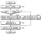
図3は、画像形成装置10によるヒータ制御処理を示すフローチャートである。まず、点灯デューティ決定部113は、点灯デューティを決定する(ステップS100)。点灯デューティ決定部113により決定された点灯デューティが閾値(30%)以下である場合には(ステップS102,Yes)、点灯デューティ決定部113は、決定された点灯デューティよりも高い点灯デューティに対応付けられている点灯パターンを点灯パターン記憶部111から抽出する(ステップS104)。なお、本実施の形態においては、40%の点灯パターンを抽出する。次に、一部点灯割当部115は、点灯パターン抽出部114により抽出された点灯パターンのうち全点灯が割り当てられている半波長に対し一部点灯を割り当てる(ステップS106)。次に、点灯制御部116は、一部点灯割当部115により一部点灯が割り当てられた点灯パターンに従いハロゲンヒータ121の点灯を制御する(ステップS120)。
FIG. 3 is a flowchart showing heater control processing by the
一方、ステップS102において、点灯デューティが閾値よりも大きい場合には(ステップS102,No)、点灯パターン抽出部114は、点灯デューティ決定部113により決定された点灯デューティに対応付けられている点灯パターンを点灯パターン記憶部111から抽出する(ステップS110)。そして、点灯制御部116は、点灯パターン抽出部114により抽出された点灯パターンに従いハロゲンヒータ121の点灯を制御する(ステップS120)。以上でヒータ制御処理が完了する。
On the other hand, when the lighting duty is larger than the threshold value in step S102 (step S102, No), the lighting
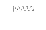
図4は、一部点灯割当部115により一部点灯が割り当てられた点灯パターンの一例を示す図である。点灯デューティ決定部113により点灯デューティが10%と決定された場合には、点灯パターン抽出部114は40%の点灯パターンを点灯パターン記憶部111から抽出する。そして、一部点灯割当部115は、図4に示すように、40%の点灯パターンのうち全点灯が割り当てられた半波長に対し、全点灯にかえて一部点灯を割り当てる。
FIG. 4 is a diagram illustrating an example of a lighting pattern in which partial lighting is assigned by the partial lighting assignment unit 115. When the lighting duty determining unit 113 determines that the lighting duty is 10%, the lighting
点灯デューティが低い場合には、制御周期内においてハロゲンヒータ121が点灯する期間が短くなる。このため、点灯パターン記憶部111に記憶されている点灯パターンを用いた点灯制御を行った場合には、消灯期間が継続することに起因した突入電流の増加が問題となる。
When the lighting duty is low, the period during which the halogen heater 121 is lit within the control cycle is shortened. For this reason, when the lighting control using the lighting pattern memorize | stored in the lighting pattern memory |
これに対し、本実施の形態にかかる画像形成装置10においては、点灯デューティにより定まる1または2以上の半波長分の点灯を複数の半波長の一部点灯に分割して制御周期内に割り当てることにより消灯期間を短くすることとした。さらに、一部点灯を割り当てる半波長については、点灯パターン記憶部111に記憶されている点灯パターンに従うこととした。これにより、突入電流の増加を抑制し、フリッカを低減させることができる。
On the other hand, in the
次に、一部点灯を割り当てる処理について説明する。本実施の形態にかかる一部点灯割当部115は、点灯パターンに割り当てられた複数の一部点灯による点灯電力の総和が、点灯デューティ決定部113により決定された点灯デューティから定まる点灯電力の総和と等しくなるように、半波長における点灯の割合を定める。さらに、各一部点灯における点灯電力が等しくなるようにする。 Next, a process for assigning partial lighting will be described. The partial lighting assignment unit 115 according to the present embodiment includes a total of lighting power determined by the lighting duty determined by the lighting duty determining unit 113, wherein the total of the lighting power due to the plurality of partial lightings assigned to the lighting pattern is The ratio of lighting at half wavelength is determined so as to be equal. Further, the lighting power in each partial lighting is made equal.
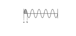
図5−1および図5−2を参照しつつ、10%の点灯デューティを40%の点灯パターンに割り当てる例について説明する。図5−1に示す、10%の点灯デューティに相当する1半波長分の全点灯の電力量は、式(1)により算出される。式(1)中、VはAC電源電圧の実行値、a、bはゼロクロスのタイミングを示している。θ(rad)は、時刻a,bにおいてsin波と交わるところの位相角である。
![]()
![]()
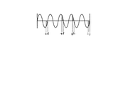
40%の点灯パターンに一部点灯を割り当てる場合には、図5−2に示すように、点灯パターンには4つの一部点灯が割り当てられる。4つの一部点灯の期間をc−d、e−f、g−hおよびi−jとした場合、4つの一部点灯の点灯電力の総和は、式(2)により算出される。したがって、点灯デューティ決定部113により決定された点灯デューティから定まる点灯電力量の総和と、点灯パターンに割り当てられた複数の一部点灯による点灯電力の総和を等しくするには、式(1)と式(2)の電力量が等しくなるように、各期間を定めればよい。
![]()
![]()
さらに、本実施の形態においては、図5−2に示す4つの一部点灯期間が同一期間となるように、各期間を定めることとする。 Further, in this embodiment, each period is determined so that the four partial lighting periods shown in FIG. 5-2 are the same period.
このように、本実施の形態にかかる画像形成装置10は、制御周期当たりの点灯回数を増加させつつ、点灯デューティ決定部113により決定された点灯デューティにより定まる点灯電力を実現するので、所望の電力供給を維持することができる。
As described above, the
さらに、本実施の形態においては、各一部点灯の期間を同一とする、すなわち均等な一部点灯を割り当てることにより、各一部点灯の点灯電力量を一定とすることにより、連続点灯時の電圧降下に差異が生じないので、電圧変動を抑制することができ、フリッカレベルを改善することができる。また、このように、各一部点灯の期間を同一期間とすることにより、制御の簡素化を図ることができる。 Furthermore, in the present embodiment, the period of each partial lighting is the same, that is, by assigning an equal partial lighting, by making the lighting power amount of each partial lighting constant, Since there is no difference in voltage drop, voltage fluctuation can be suppressed and flicker level can be improved. In addition, the control can be simplified by setting each partial lighting period to the same period.
以上のように、第1の実施の形態にかかる画像形成装置10によれば、決定された点灯デューティが低い場合には、フリッカを回避するように設定された点灯パターンに、必要な点灯デューティ分の点灯を一部点灯として割り当てることにより、高調波電流、雑音端子電圧のレベル低下を抑制しつつ、フリッカレベルを改善することができる。
As described above, according to the
なお、半波長の一部に点灯を割り当てる位相制御においては、高調波電流や雑音端子電圧のレベル悪化が問題となる。これに対し、本実施の形態においては、例えば40%点灯パターンにおける全点灯の期間のみ位相制御とするように、位相制御回数を間引くこととしたので、高調波電流や雑音端子電圧のレベル悪化を抑制することができる。 In the phase control in which lighting is assigned to a part of the half wavelength, the level deterioration of the harmonic current and the noise terminal voltage becomes a problem. On the other hand, in the present embodiment, for example, the number of phase controls is thinned out so that the phase control is performed only during the full lighting period in the 40% lighting pattern. Can be suppressed.
本実施の形態の第1の変更例について説明する。本実施の形態にかかる画像形成装置10においては、点灯デューティ決定部113により決定された点灯デューティが30%以下である場合に、一部点灯を割り当てる点灯パターンを40%の点灯パターンとしたが、これにかえて60%の点灯パターンとしてもよい。図6は、60%の点灯デューティに1半波長10%点灯デューティ分の一部点灯を割り当てた点灯パターンを示す図である。
A first modification of the present embodiment will be described. In the
60%点灯パターンは、40%点灯パターンに比べて点灯の割合が多いことから、高調波電流や雑音端子電圧のレベルは悪化させるものの、突入電流を低減させることができる。したがって、装置の特性等に基づいて、40%と60%のうちいずれの点灯パターンを抽出することとするかを設定するのが好ましい。 Since the 60% lighting pattern has a higher lighting ratio than the 40% lighting pattern, the inrush current can be reduced although the level of the harmonic current and the noise terminal voltage is deteriorated. Therefore, it is preferable to set which lighting pattern to extract from 40% or 60% based on the characteristics of the device.
例えばハロゲンヒータ121の定格電力が比較的大容量であり、フリッカレベルの改善が優先される場合には、点灯回数を多くし、一点灯当たりの電力供給を少なくするのが好ましい。したがって、この場合には60%の点灯パターンを用いるのが有効である。 For example, when the rated power of the halogen heater 121 is relatively large and priority is given to improving the flicker level, it is preferable to increase the number of times of lighting and reduce the power supply per lighting. Therefore, in this case, it is effective to use a 60% lighting pattern.
一方で、ハロゲンヒータ121の定格電力が比較的小容量であり、高調波電流および雑音端子電圧のレベル悪化の抑制が優先される場合には、点灯回数を減らし、位相制御の回数を抑えるのが好ましい。したがって、この場合には40%の点灯パターンを用いるのが有効である。 On the other hand, when the rated power of the halogen heater 121 is relatively small and priority is given to suppressing the deterioration of the harmonic current and the noise terminal voltage level, the number of lightings is reduced and the number of phase controls is suppressed. preferable. Therefore, in this case, it is effective to use a 40% lighting pattern.
また、第2の変更例としては、点灯パターン抽出部114は、点灯デューティ決定部113により決定された点灯デューティが閾値である30%以下である場合に、一部点灯を割り当てる点灯パターンを、決定された点灯デューティに応じて異ならせてもよい。例えば、点灯デューティ10%と決定された場合には、40%の点灯パターンを抽出し、点灯デューティ20%と決定された場合には、60%の点灯パターンを抽出することとしてもよい。またこれとは逆に、点灯デューティ10%および20%と決定された場合に、それぞれ60%および40%の点灯パターンを抽出してもよい。
As a second modification, the lighting
また、第3の変更例としては、一部点灯割当部115が、決定された点灯パターンに割り当てる複数の一部点灯の電力量を異ならせてもよい。例えば、図7に示すように、一部点灯割当部115は、点灯パターンの先頭から最後尾にかけて徐々に点灯電力が大きくなるような複数の一部点灯を割り当ててもよい。これにより、ハロゲンヒータ121の点灯時の電圧変動を抑制することができる。 As a third modification, the partial lighting assignment unit 115 may vary the power amounts of a plurality of partial lightings assigned to the determined lighting pattern. For example, as shown in FIG. 7, the partial lighting allocation unit 115 may allocate a plurality of partial lightings that gradually increase the lighting power from the beginning to the end of the lighting pattern. Thereby, the voltage fluctuation at the time of lighting of the halogen heater 121 can be suppressed.
また、他の例としては、図8に示すように、一部点灯割当部115は、点灯パターンの先頭から最後尾にかけて徐々に点灯電力が小さくなるような複数の一部点灯を割り当ててもよい。これにより、ハロゲンヒータ121の消灯時の電圧変動を抑制することができる。 As another example, as shown in FIG. 8, the partial lighting assignment unit 115 may assign a plurality of partial lightings that gradually reduce the lighting power from the beginning to the end of the lighting pattern. . Thereby, voltage fluctuation when the halogen heater 121 is turned off can be suppressed.
また、他の例としては、図9または図10に示すように、一部点灯割当部115は、一部点灯だけでなく全点灯を割り当ててもよい。なお、このように、複数の一部点灯の電力量を異ならせる場合においても、点灯パターンに割り当てられた複数の一部点灯の点灯電力量の総和が決定されたデューティにより定まる電力量と等しくなるよう、各一部点灯の期間を決定することとする。 As another example, as shown in FIG. 9 or FIG. 10, the partial lighting assignment unit 115 may assign not only partial lighting but full lighting. In this way, even when the plurality of partial lighting power amounts are made different, the sum of the plurality of partial lighting power amounts assigned to the lighting pattern is equal to the electric energy determined by the determined duty. In this way, the period of partial lighting is determined.
また、第4の変更例としては、一部点灯割当部115は、比較的長期の制御として、ハロゲンヒータ121の点灯開始後の一定期間においては図7に示すように、徐々に点灯電力が増加するような点灯パターンを割り当て、その後は、図4や図6に示すように一定の点灯電力の点灯パターンを割り当て、ハロゲンヒータ121の消灯前の一定期間においては、図8に示すように、徐々に点灯電力が減少するような点灯パターンを割り当てることとしてもよい。 Further, as a fourth modification example, the partial lighting allocation unit 115 gradually increases the lighting power as shown in FIG. 7 in a certain period after the start of lighting of the halogen heater 121 as a relatively long-term control. After that, a lighting pattern with a constant lighting power is assigned as shown in FIGS. 4 and 6, and during a certain period before the halogen heater 121 is turned off, as shown in FIG. It is good also as assigning the lighting pattern that lighting power decreases to.
本実施の形態の画像形成装置は、CPUなどの制御装置と、ROMやRAMなどの記憶装置と、HDD、CDドライブ装置などの外部記憶装置とを備えており、通常のコンピュータを利用したハードウェア構成となっている。 The image forming apparatus according to the present embodiment includes a control device such as a CPU, a storage device such as a ROM and a RAM, and an external storage device such as an HDD and a CD drive device, and hardware using a normal computer. It has a configuration.
本実施形態の画像形成装置で実行されるヒータ制御プログラムは、インストール可能な形式又は実行可能な形式のファイルでCD−ROM、フレキシブルディスク(FD)、CD−R、DVD(Digital Versatile Disk)等のコンピュータで読み取り可能な記録媒体に記録されて提供される。 The heater control program executed in the image forming apparatus according to the present embodiment is a file in an installable or executable format, such as a CD-ROM, a flexible disk (FD), a CD-R, a DVD (Digital Versatile Disk), or the like. The program is provided by being recorded on a computer-readable recording medium.
また、本実施形態の画像形成装置で実行されるヒータ制御プログラムを、インターネット等のネットワークに接続されたコンピュータ上に格納し、ネットワーク経由でダウンロードさせることにより提供するように構成しても良い。また、本実施形態の画像形成装置で実行されるヒータ制御プログラムをインターネット等のネットワーク経由で提供または配布するように構成しても良い。 The heater control program executed by the image forming apparatus according to the present embodiment may be stored on a computer connected to a network such as the Internet and provided by being downloaded via the network. The heater control program executed by the image forming apparatus according to the present embodiment may be provided or distributed via a network such as the Internet.
また、本実施形態のヒータ制御プログラムを、ROM等に予め組み込んで提供するように構成してもよい。 Further, the heater control program according to the present embodiment may be provided by being incorporated in advance in a ROM or the like.
本実施の形態の画像形成装置で実行されるヒータ制御プログラムは、上述した各部(点灯デューティ決定部、点灯パターン抽出部、一部点灯割当部、点灯制御部)を含むモジュール構成となっており、実際のハードウェアとしてはCPU(プロセッサ)が上記記憶媒体からヒータ制御プログラムを読み出して実行することにより上記各部が主記憶装置上にロードされ、各部が主記憶装置上に生成されるようになっている。 The heater control program executed in the image forming apparatus according to the present embodiment has a module configuration including the above-described units (lighting duty determination unit, lighting pattern extraction unit, partial lighting allocation unit, lighting control unit), As actual hardware, a CPU (processor) reads out and executes a heater control program from the storage medium, whereby each unit is loaded on the main storage device, and each unit is generated on the main storage device. Yes.
なお、上記実施の形態では、本発明の画像形成装置は、コピー機能、プリンタ機能、スキャナ機能およびファクシミリ機能のうち少なくとも2つの機能を有する複合機であってもよく、複写機、プリンタ、スキャナ装置、ファクシミリ装置等の画像形成装置であればいずれにも適用することができる。 In the above embodiment, the image forming apparatus of the present invention may be a multi-function machine having at least two functions among a copy function, a printer function, a scanner function, and a facsimile function. The present invention can be applied to any image forming apparatus such as a facsimile apparatus.
10 画像形成装置
100 メイン電源
101 AC電源
102 フィルタ
103 整流ダイオード
104 平滑コンデンサ
106 電磁リレー
107 スイッチ
108 ゼロクロス検知回路
110 制御基板
111 点灯パターン記憶部
112 制御部
113 点灯デューティ決定部
114 点灯パターン抽出部
115 一部点灯割当部
116 点灯制御部
120 定着ユニット
121 ハロゲンヒータ
122 サーミスタ
141 電源SW
142 ドアSW
143 TRI
DESCRIPTION OF
142 Door SW
143 TRI
Claims (19)
前記ヒータに交流電圧を印加する交流電源と、
前記加熱対象物の温度と目標温度に基づいて、前記ヒータの点灯比率を決定する点灯比率決定手段と、
所定の制御周期を単位とするパターンであって、フリッカを回避するように、前記制御周期内の前記交流電圧の半波長に全点灯または全消灯が割り当てられた点灯パターンを記憶する点灯パターン記憶手段と、
決定された前記点灯比率が閾値以下である場合に、前記点灯パターン記憶手段において、前記点灯比率決定手段により決定された前記点灯比率よりも高い点灯比率に対応付けられている前記点灯パターンを抽出する点灯パターン抽出手段と、
抽出された前記点灯パターンにおいて全点灯が割り当てられている半波長に対し、前記全点灯にかえて一部点灯を割り当てる一部点灯割当手段と、
一部点灯が割り当てられた前記点灯パターンに基づいて、前記ヒータの点灯を制御する点灯制御手段と
を備えたことを特徴とするヒータ制御装置。 Temperature detecting means for detecting the temperature of the heating object heated by the heater;
An AC power supply for applying an AC voltage to the heater;
A lighting ratio determining means for determining a lighting ratio of the heater based on the temperature of the heating object and a target temperature;
A lighting pattern storage means for storing a lighting pattern in which all lighting or all lighting is assigned to a half wavelength of the AC voltage in the control cycle so as to avoid flicker, the pattern being a unit of a predetermined control cycle When,
When the determined lighting ratio is less than or equal to a threshold value, the lighting pattern storage means extracts the lighting pattern associated with a lighting ratio higher than the lighting ratio determined by the lighting ratio determining means. Lighting pattern extraction means;
Partial lighting assignment means for assigning partial lighting instead of full lighting for half wavelength to which full lighting is assigned in the extracted lighting pattern;
A heater control device comprising: a lighting control unit that controls lighting of the heater based on the lighting pattern to which partial lighting is assigned.
前記ヒータに交流電圧を印加する交流電源と、
前記加熱対象物の温度と目標温度に基づいて、前記ヒータの点灯比率を決定する点灯比率決定手段と、
所定の制御周期を単位とするパターンであって、フリッカを回避するように、前記制御周期内の前記交流電圧の半波長に全点灯または全消灯が割り当てられた点灯パターンを記憶する点灯パターン記憶手段と、
決定された前記点灯比率が閾値以下である場合に、前記点灯パターン記憶手段において、前記点灯比率決定手段により決定された前記点灯比率よりも高い点灯比率に対応付けられている前記点灯パターンを抽出する点灯パターン抽出手段と、
抽出された前記点灯パターンにおいて全点灯が割り当てられている半波長に対し、前記全点灯にかえて一部点灯を割り当てる一部点灯割当手段と、
一部点灯が割り当てられた前記点灯パターンに基づいて、前記ヒータの点灯を制御する点灯制御手段と
を備えたことを特徴とする画像形成装置。 Temperature detecting means for detecting the temperature of the heating object heated by the heater;
An AC power supply for applying an AC voltage to the heater;
A lighting ratio determining means for determining a lighting ratio of the heater based on the temperature of the heating object and a target temperature;
A lighting pattern storage means for storing a lighting pattern in which all lighting or all lighting is assigned to a half wavelength of the AC voltage in the control cycle so as to avoid flicker, the pattern being a unit of a predetermined control cycle When,
When the determined lighting ratio is less than or equal to a threshold value, the lighting pattern storage means extracts the lighting pattern associated with a lighting ratio higher than the lighting ratio determined by the lighting ratio determining means. Lighting pattern extraction means;
Partial lighting assignment means for assigning partial lighting instead of full lighting for half wavelength to which full lighting is assigned in the extracted lighting pattern;
An image forming apparatus comprising: a lighting control unit that controls lighting of the heater based on the lighting pattern to which partial lighting is assigned.
前記コンピュータは、
所定の制御周期を単位とするパターンであって、フリッカを回避するように、前記制御周期内のヒータに印加される交流電圧の半波長に全点灯または全消灯が割り当てられた点灯パターンを記憶する点灯パターン記憶手段を備え、
前記コンピュータに、
前記加熱対象物の温度と目標温度に基づいて、前記ヒータの点灯比率を決定する点灯比率決定ステップと、
決定された前記点灯比率が閾値以下である場合に、前記点灯パターン記憶手段において、前記点灯比率決定ステップで決定された前記点灯比率よりも高い点灯比率に対応付けられている前記点灯パターンを抽出する点灯パターン抽出ステップと、
抽出された前記点灯パターンにおいて全点灯が割り当てられている半波長に対し、前記全点灯にかえて一部点灯を割り当てる一部点灯割当ステップと、
一部点灯が割り当てられた前記点灯パターンに基づいて、前記ヒータの点灯を制御する点灯制御ステップと
を前記コンピュータに実行させるためのプログラム。 A program for causing a computer to execute a heater control process,
The computer
A pattern having a predetermined control cycle as a unit and storing a lighting pattern in which full lighting or full lighting is assigned to the half wavelength of the AC voltage applied to the heater in the control cycle is stored so as to avoid flicker. With lighting pattern storage means,
In the computer,
A lighting ratio determination step for determining a lighting ratio of the heater based on the temperature of the heating object and a target temperature;
When the determined lighting ratio is equal to or less than a threshold value, the lighting pattern storage unit extracts the lighting pattern associated with a lighting ratio higher than the lighting ratio determined in the lighting ratio determination step. Lighting pattern extraction step;
A partial lighting assignment step for assigning partial lighting instead of the full lighting for the half wavelength to which full lighting is assigned in the extracted lighting pattern;
A program for causing the computer to execute a lighting control step for controlling lighting of the heater based on the lighting pattern to which partial lighting is assigned.
Priority Applications (4)
| Application Number | Priority Date | Filing Date | Title |
|---|---|---|---|
| JP2009212610A JP5321380B2 (en) | 2009-09-15 | 2009-09-15 | HEATER CONTROL DEVICE, IMAGE FORMING DEVICE, AND PROGRAM |
| US12/881,708 US8530800B2 (en) | 2009-09-15 | 2010-09-14 | Heater control device, image forming apparatus, and computer program product |
| EP10176636.8A EP2296057B1 (en) | 2009-09-15 | 2010-09-14 | Heater control device, image forming apparatus, and computer program product |
| CN2010102864217A CN102023660B (en) | 2009-09-15 | 2010-09-15 | Heater control device and image forming apparatus |
Applications Claiming Priority (1)
| Application Number | Priority Date | Filing Date | Title |
|---|---|---|---|
| JP2009212610A JP5321380B2 (en) | 2009-09-15 | 2009-09-15 | HEATER CONTROL DEVICE, IMAGE FORMING DEVICE, AND PROGRAM |
Publications (2)
| Publication Number | Publication Date |
|---|---|
| JP2011064712A JP2011064712A (en) | 2011-03-31 |
| JP5321380B2 true JP5321380B2 (en) | 2013-10-23 |
Family
ID=43951074
Family Applications (1)
| Application Number | Title | Priority Date | Filing Date |
|---|---|---|---|
| JP2009212610A Active JP5321380B2 (en) | 2009-09-15 | 2009-09-15 | HEATER CONTROL DEVICE, IMAGE FORMING DEVICE, AND PROGRAM |
Country Status (1)
| Country | Link |
|---|---|
| JP (1) | JP5321380B2 (en) |
Families Citing this family (4)
| Publication number | Priority date | Publication date | Assignee | Title |
|---|---|---|---|---|
| JP5573481B2 (en) * | 2010-08-10 | 2014-08-20 | 株式会社リコー | Heater control apparatus, image forming apparatus, heater control method, and computer-executable program |
| JP5942400B2 (en) * | 2011-12-01 | 2016-06-29 | 株式会社リコー | HEATER CONTROL DEVICE, IMAGE FORMING DEVICE, AND HEATER CONTROL METHOD |
| JP6269627B2 (en) * | 2015-09-18 | 2018-01-31 | コニカミノルタ株式会社 | Fixing apparatus and image forming apparatus |
| JP2017078824A (en) * | 2015-10-22 | 2017-04-27 | コニカミノルタ株式会社 | Heating device and image forming apparatus |
Family Cites Families (2)
| Publication number | Priority date | Publication date | Assignee | Title |
|---|---|---|---|---|
| JP2004212510A (en) * | 2002-12-27 | 2004-07-29 | Canon Inc | Image forming apparatus |
| JP2008070686A (en) * | 2006-09-15 | 2008-03-27 | Ricoh Co Ltd | Fixing device and image forming apparatus |
-
2009
- 2009-09-15 JP JP2009212610A patent/JP5321380B2/en active Active
Also Published As
| Publication number | Publication date |
|---|---|
| JP2011064712A (en) | 2011-03-31 |
Similar Documents
| Publication | Publication Date | Title |
|---|---|---|
| US8530800B2 (en) | Heater control device, image forming apparatus, and computer program product | |
| JP5471618B2 (en) | HEATER CONTROL DEVICE, IMAGE FORMING DEVICE, HEATER CONTROL METHOD, AND PROGRAM | |
| US8260165B2 (en) | Image forming apparatus and heater control method | |
| JP5569063B2 (en) | HEATER CONTROL DEVICE, IMAGE FORMING DEVICE, HEATER CONTROL METHOD, PROGRAM | |
| JP5321380B2 (en) | HEATER CONTROL DEVICE, IMAGE FORMING DEVICE, AND PROGRAM | |
| JP2017511586A5 (en) | ||
| JP2017511586A (en) | System and method for minimizing power dissipation in a low power lamp coupled to a trailing edge dimmer | |
| JP2018087922A (en) | Heater controller, heater control method and program | |
| JP5614188B2 (en) | HEATER CONTROL DEVICE, IMAGE FORMING DEVICE, AND PROGRAM | |
| JP5573481B2 (en) | Heater control apparatus, image forming apparatus, heater control method, and computer-executable program | |
| JP5375477B2 (en) | HEATER CONTROL DEVICE, IMAGE FORMING DEVICE, HEATER CONTROL METHOD, AND HEATER CONTROL PROGRAM | |
| JP5397151B2 (en) | HEATER CONTROL DEVICE, IMAGE FORMING DEVICE, HEATER CONTROL METHOD, AND PROGRAM | |
| JP2002268447A (en) | Electrophotographic device | |
| JP2003219688A (en) | Apparatus and method for suppressing low-speed ripple current in single-phase inverter | |
| JP6690286B2 (en) | Heating device and image forming device | |
| JP6091178B2 (en) | LIGHT SOURCE DEVICE, ELECTRONIC DEVICE, AND CONTROL METHOD THEREOF | |
| JP2017084716A (en) | Lighting device and luminaire | |
| JP2021044086A (en) | Heater control device, image forming apparatus, control method for heater, and control program for heater | |
| JP5446645B2 (en) | HEATER CONTROL DEVICE, HEATER CONTROL METHOD, AND PROGRAM | |
| JP2005267996A (en) | Induction heating device | |
| JP5167695B2 (en) | Image forming apparatus | |
| JPH1152785A (en) | Image forming device | |
| JP2023084830A (en) | Induction heating cooker | |
| JP2008234875A (en) | Discharge lamp lighting device | |
| JP2004024645A (en) | Rice cooker |
Legal Events
| Date | Code | Title | Description |
|---|---|---|---|
| A621 | Written request for application examination |
Free format text: JAPANESE INTERMEDIATE CODE: A621 Effective date: 20120705 |
|
| A977 | Report on retrieval |
Free format text: JAPANESE INTERMEDIATE CODE: A971007 Effective date: 20130606 |
|
| TRDD | Decision of grant or rejection written | ||
| A01 | Written decision to grant a patent or to grant a registration (utility model) |
Free format text: JAPANESE INTERMEDIATE CODE: A01 Effective date: 20130618 |
|
| A61 | First payment of annual fees (during grant procedure) |
Free format text: JAPANESE INTERMEDIATE CODE: A61 Effective date: 20130701 |
|
| R151 | Written notification of patent or utility model registration |
Ref document number: 5321380 Country of ref document: JP Free format text: JAPANESE INTERMEDIATE CODE: R151 |