JP5390865B2 - Stereo imaging device - Google Patents
Stereo imaging device Download PDFInfo
- Publication number
- JP5390865B2 JP5390865B2 JP2009008189A JP2009008189A JP5390865B2 JP 5390865 B2 JP5390865 B2 JP 5390865B2 JP 2009008189 A JP2009008189 A JP 2009008189A JP 2009008189 A JP2009008189 A JP 2009008189A JP 5390865 B2 JP5390865 B2 JP 5390865B2
- Authority
- JP
- Japan
- Prior art keywords
- image capturing
- objective lens
- optical axis
- unit
- stereoscopic image
- Prior art date
- Legal status (The legal status is an assumption and is not a legal conclusion. Google has not performed a legal analysis and makes no representation as to the accuracy of the status listed.)
- Expired - Fee Related
Links
Images


Description
本発明は、立体画像撮影装置に関する。 The present invention relates to a stereoscopic image capturing apparatus.
スチルカメラやビデオカメラを用いて視差のある画像を撮影する立体画像撮影装置に関する技術が知られている。一般的な立体画像撮影装置は、2台のカメラを使用して視差のある画像を撮影している。このような装置では、2台のカメラの間隔(基線長)を、カメラ自体を移動させることにより調節している。従来の立体画像撮影装置では、装置全体が大型化したり、衝撃などにより簡単に光軸ずれが発生したりする場合がある。上記のような不具合を解消するための技術が知られている(例えば、特許文献1参照)。 A technique related to a stereoscopic image capturing apparatus that captures an image with parallax using a still camera or a video camera is known. A general stereoscopic image capturing apparatus captures an image with parallax using two cameras. In such an apparatus, the interval (base line length) between two cameras is adjusted by moving the cameras themselves. In a conventional stereoscopic image capturing apparatus, the entire apparatus may be increased in size or the optical axis may be easily shifted due to an impact or the like. A technique for solving the above problems is known (see, for example, Patent Document 1).
特許文献1(特開2002−112288号公報)には、左側光学系および右側光学系を有し、これら左側および右側光学系を通して単一のカメラに立体観察が可能な画像の撮影を行わせる立体撮影光学ユニットに関する技術が記載されている。その立体撮影光学ユニットは、左側および右側光学系の左右方向における相対間隔を変更する間隔変更手段を備えている。 Patent Document 1 (Japanese Patent Laid-Open No. 2002-112288) has a left optical system and a right optical system, and allows a single camera to take an image capable of stereoscopic observation through the left and right optical systems. A technique related to the photographing optical unit is described. The stereoscopic imaging optical unit includes an interval changing unit that changes the relative interval between the left and right optical systems in the left-right direction.
従来の立体画像撮影装置では、間隔変更手段の作用によって、左右の光軸ずれ等のない状態で視差画像を創出するとともに、左右の光学系の基線長を焦点距離や対物距離又は輻輳距離に応じて調節されている。 In a conventional stereoscopic image capturing device, a parallax image is created in a state where there is no left-right optical axis deviation or the like by the action of the interval changing means, and the baseline length of the left and right optical systems is set according to the focal length, objective distance, or convergence distance. Have been adjusted.
その従来の立体画像撮影装置で調節可能な基線長の長さは、間隔変更手段の構造と光学系の構造とによって制限されている。より自由度の高い立体画像の撮影を可能とする立体画像撮影装置が求められている。 The length of the base line length that can be adjusted by the conventional stereoscopic image capturing apparatus is limited by the structure of the interval changing means and the structure of the optical system. There is a need for a stereoscopic image capturing apparatus that can capture a stereoscopic image with a higher degree of freedom.
以下に、[発明を実施するための形態]で使用される番号を用いて、課題を解決するための手段を説明する。これらの番号は、[特許請求の範囲]の記載と[発明を実施するための形態]との対応関係を明らかにするために付加されたものである。ただし、それらの番号を、[特許請求の範囲]に記載されている発明の技術的範囲の解釈に用いてはならない。 Hereinafter, means for solving the problem will be described using the numbers used in [DETAILED DESCRIPTION]. These numbers are added to clarify the correspondence between the description of [Claims] and [Mode for Carrying Out the Invention]. However, these numbers should not be used to interpret the technical scope of the invention described in [Claims].
上述の課題を解決するために、第1対物レンズ(2−1)と第1結像レンズ(2−2)とを有し、右画像を撮像するための光を結像部(6)に供給する右画像撮像ユニット(2)と、第2対物レンズ(3−1)と第2結像レンズ(3−2)とを有し、左画像を撮像するための光を前記結像部(6)に供給する左画像撮像ユニット(3)と、前記右画像と前記左画像とを撮像するときの基線長を変更する基線長変更ユニット(18)(13)と、前記右画像と前記左画像とを撮像するときの輻輳角を変更する輻輳角変更ユニット(4)とを具備する立体画像撮影装置(1)を構成する。 In order to solve the above-mentioned problem, the first objective lens (2-1) and the first imaging lens (2-2) are provided, and light for capturing a right image is input to the imaging unit (6). A right image pickup unit (2) to be supplied, a second objective lens (3-1), and a second imaging lens (3-2), and the light for taking a left image is sent to the imaging unit ( 6) the left image capturing unit (3) to be supplied, the baseline length changing unit (18) (13) for changing the baseline length when capturing the right image and the left image, the right image and the left A stereoscopic image capturing apparatus (1) including a convergence angle changing unit (4) for changing a convergence angle when capturing an image is configured.
その立体画像撮影装置(1)において、前記右画像撮像ユニット(2)と前記左画像撮像ユニット(3)は、前記結像部(6)の受光面の法線に平行な回転対称軸(5)を基準に回転対称に配置されるものとする。また、前記右画像撮像ユニット(2)は、前記第1対物レンズ(2−1)と前記第2対物レンズ(3−1)との基線長が最小のとき、前記法線の方向に平行投影した前記第1対物レンズ(2−1)の投影面が、前記第1結像レンズ(2−2)または前記第2結像レンズ(3−2)の投影面に重なる位置に配置され、前記左画像撮像ユニット(3)は、前記第1対物レンズ(2−1)と前記第2対物レンズ(3−1)との基線長が最小のとき、前記法線の方向に平行投影した前記第2対物レンズ(3−1)の投影面が、前記第1結像レンズ(2−2)または前記第2結像レンズ(3−2)の投影面に重なる位置に配置されることが好ましい。 In the stereoscopic image capturing apparatus (1), the right image capturing unit (2) and the left image capturing unit (3) have a rotationally symmetric axis (5) parallel to the normal line of the light receiving surface of the imaging unit (6). ) With respect to the rotation. In addition, the right image pickup unit (2) performs parallel projection in the direction of the normal line when the baseline length of the first objective lens (2-1) and the second objective lens (3-1) is minimum. The projection surface of the first objective lens (2-1) is disposed at a position overlapping the projection surface of the first imaging lens (2-2) or the second imaging lens (3-2), and When the baseline length of the first objective lens (2-1) and the second objective lens (3-1) is the minimum, the left image pickup unit (3) is configured to perform the parallel projection in the direction of the normal line. It is preferable that the projection surface of the two objective lens (3-1) is disposed at a position overlapping the projection surface of the first imaging lens (2-2) or the second imaging lens (3-2).
その立体画像撮影装置(1)において、前記輻輳角変更ユニット(4)は、前記基線長に依存することなく前記第1対物レンズ(2−1)と前記第2対物レンズ(3−1)との輻輳角を変更する機能を備えていることがこのましい。また、前記基線長変更ユニット(18)(13)は、前記輻輳角に依存することなく前記第1対物レンズ(2−1)と前記第2対物レンズ(3−1)との基線長を変更することが好ましい。 In the stereoscopic image capturing apparatus (1), the convergence angle changing unit (4) includes the first objective lens (2-1), the second objective lens (3-1), and the second objective lens (3-1) without depending on the baseline length. It is preferable to have a function to change the convergence angle of the. The baseline length changing unit (18) (13) changes the baseline length of the first objective lens (2-1) and the second objective lens (3-1) without depending on the convergence angle. It is preferable to do.
その立体画像撮影装置(1)において、前記右画像撮像ユニット(2)は、前記第1対物レンズ(2−1)と前記第1結像レンズ(2−2)との間に配置され、前記第1対物レンズ(2−1)を通った第1光線を反射させて前記第1結像レンズ(2−2)に供給する右側反射装置群(21、22、23、24)を備えていることが好ましい。また、前記左画像撮像ユニット(3)は、前記第2対物レンズ(3−1)と前記第2結像レンズ(3−2)との間に配置され、前記第2対物レンズ(3−1)を通った第2光線を反射させて前記第2結像レンズ(3−2)に供給する左側反射装置群(31、32、33、34)を備えていることが好ましい。そのうえで、前記右側反射装置群(21、22、23、24)は、前記第1光線を、前記第1対物レンズ(2−1)の光軸と前記第2対物レンズ(3−1)の光軸との各々を含む平面と異なる位置に反射させる。また、前記左側反射装置群(31、32、33、34)は、前記第2光線を、前記第1対物レンズ(2−1)の光軸と前記第2対物レンズ(3−1)の光軸との各々を含む平面と異なる位置に反射させる。 In the stereoscopic image capturing device (1), the right image capturing unit (2) is disposed between the first objective lens (2-1) and the first imaging lens (2-2), and A right-side reflecting device group (21, 22, 23, 24) that reflects the first light beam that has passed through the first objective lens (2-1) and supplies the first light beam to the first imaging lens (2-2) is provided. It is preferable. The left image pickup unit (3) is disposed between the second objective lens (3-1) and the second imaging lens (3-2), and the second objective lens (3-1). It is preferable to include a left reflecting device group (31, 32, 33, 34) that reflects the second light beam that has passed through the second imaging lens (3-2) and supplies it to the second imaging lens (3-2). In addition, the right reflector group (21, 22, 23, 24) transmits the first light beam to the optical axis of the first objective lens (2-1) and the light of the second objective lens (3-1). Reflection is performed at a position different from a plane including each of the axes. The left reflector group (31, 32, 33, 34) transmits the second light beam to the optical axis of the first objective lens (2-1) and the light beam of the second objective lens (3-1). Reflection is performed at a position different from a plane including each of the axes.
その立体画像撮影装置(1)において、前記右側反射装置群(21、22、23、24)は、前記第1光線を前記平面と異なる方向に反射させて第1反射光とする第1反射装置(21)と、前記第1反射光を前記第1対物レンズ(2−1)の光軸に平行な方向に反射させて第2反射光とする第2反射装置(22)と、前記第2反射光を反射させて第3反射光とする第3反射装置(23)と、前記第3反射光を前記第1光軸に平行な方向に反射させて第4反射光として前記第1結像レンズ(2−2)に供給する第4反射装置(24)とを含むことが好ましい。 In the stereoscopic image capturing device (1), the right reflecting device group (21, 22, 23, 24) reflects the first light beam in a direction different from the plane to form a first reflected light. (21), a second reflection device (22) that reflects the first reflected light in a direction parallel to the optical axis of the first objective lens (2-1) to form second reflected light, and the second A third reflection device (23) that reflects the reflected light to form third reflected light, and reflects the third reflected light in a direction parallel to the first optical axis to form the first image as fourth reflected light. It is preferable to include a fourth reflecting device (24) that supplies the lens (2-2).
ここにおいて、前記第1反射装置(21)の反射面と前記第2反射装置(22)の反射面とは互いに平行に配置され、前記第3反射装置(23)の反射面と前記第4反射装置(24)の反射面とは互いに平行に配置され、そして、前記第2反射装置(22)の反射面と前記第3反射装置(23)の反射面は、各々の面に交差する軸を共通に回転することが好ましい。 Here, the reflecting surface of the first reflecting device (21) and the reflecting surface of the second reflecting device (22) are arranged in parallel to each other, and the reflecting surface of the third reflecting device (23) and the fourth reflecting device are arranged. The reflecting surface of the device (24) is arranged in parallel with each other, and the reflecting surface of the second reflecting device (22) and the reflecting surface of the third reflecting device (23) have axes intersecting with each surface. It is preferable to rotate in common.
また、前記左側反射装置群(31、32、33、34)は、前記第2光線を前記平面と異なる方向に反射させて第5反射光とする第5反射装置(31)と、前記第5反射光を前記第2対物レンズ(3−1)の光軸に平行な方向に反射させて第6反射光とする第6反射装置(32)と、前記第6反射光を反射させ第7反射光とする第7反射装置(33)と、前記第7反射光を前記第2光軸に平行な方向に反射させて第8反射光として前記第2結像レンズ(3−2)に供給する第8反射装置(34)とを含むことが好ましい。 The left reflecting device group (31, 32, 33, 34) includes a fifth reflecting device (31) configured to reflect the second light beam in a direction different from the plane to be a fifth reflected light, and the fifth reflecting device. A sixth reflecting device (32) that reflects the reflected light in a direction parallel to the optical axis of the second objective lens (3-1) to form a sixth reflected light, and a seventh reflection that reflects the sixth reflected light. A seventh reflecting device (33) for making light, and the seventh reflected light is reflected in a direction parallel to the second optical axis and supplied to the second imaging lens (3-2) as eighth reflected light; And an eighth reflecting device (34).
ここにおいて、前記第5反射装置(31)の反射面と前記第6反射装置(32)の反射面とは互いに平行に配置され、前記第7反射装置(33)の反射面と前記第8反射装置(34)の反射面とは互いに平行に配置され、前記第6反射装置(32)の反射面と前記第7反射装置(33)の反射面は、各々の面に交差する軸を共通に回転することが好ましい。 Here, the reflecting surface of the fifth reflecting device (31) and the reflecting surface of the sixth reflecting device (32) are arranged in parallel with each other, and the reflecting surface of the seventh reflecting device (33) and the eighth reflecting device are arranged. The reflecting surface of the device (34) is arranged in parallel to each other, and the reflecting surface of the sixth reflecting device (32) and the reflecting surface of the seventh reflecting device (33) have a common axis intersecting each surface. It is preferable to rotate.
その立体画像撮影装置(1)において、前記第2反射装置(22)と前記第3反射装置(23)とを結ぶ第1の反射光線経路は、前記第1光軸に対し回転移動し、前記第1光線の光軸は、前記第1の反射光線経路の回転移動に対応して平行移動し、前記第6反射装置(32)と前記第7反射装置(33)とを結ぶ第2の反射光線経路は、前記第2光軸に対し回転移動し、前記第2光線の光軸は、前記第2の反射光線経路の回転移動に対応して平行移動することが好ましい。 In the stereoscopic image capturing device (1), a first reflected light path connecting the second reflecting device (22) and the third reflecting device (23) rotates and moves with respect to the first optical axis, and The optical axis of the first light beam is translated corresponding to the rotational movement of the first reflected light beam path, and the second reflection that connects the sixth reflecting device (32) and the seventh reflecting device (33). It is preferable that the light path rotates relative to the second optical axis, and the optical axis of the second light moves in parallel with the rotational movement of the second reflected light path.
その立体画像撮影装置(1)において、前記第1結像レンズ(2−2)は、第1光軸を有し、前記第2結像レンズ(3−2)は、第2光軸を有するものとするとき、前記第1光軸は、第1交点において前記受光面と交差し、前記第2光軸は、第2交点において前記受光面と交差するものとする。ここにおいて、前記輻輳角変更ユニット(4)は、前記第1交点と前記第2交点とから等距離に位置し、前記第1対物レンズ(2−1)の光軸(7)と前記第2対物レンズ(3−1)の光軸(8)との各々を含む平面に垂直な線を軸に、前記右画像撮像ユニット(2)と前記左画像撮像ユニット(3)とを回転運動させる。 In the stereoscopic image capturing apparatus (1), the first imaging lens (2-2) has a first optical axis, and the second imaging lens (3-2) has a second optical axis. In this case, the first optical axis intersects with the light receiving surface at a first intersection, and the second optical axis intersects with the light receiving surface at a second intersection. Here, the convergence angle changing unit (4) is located equidistant from the first intersection and the second intersection, and the optical axis (7) of the first objective lens (2-1) and the second The right image capturing unit (2) and the left image capturing unit (3) are rotated about a line perpendicular to a plane including each of the optical axis (8) of the objective lens (3-1).
その立体画像撮影装置(1)において、前記基線長変更ユニット(18)(13)は、前記第1対物レンズ(2−1)の光軸と前記第2対物レンズ(3−1)の光軸との各々を含む平面が、前記前記基線長の変化に依存することなく被写体に対し固定となるように、前記第1対物レンズ(2−1)と前記第2対物レンズ(3−1)とを移動させる。 In the stereoscopic image capturing apparatus (1), the base length changing unit (18) (13) includes an optical axis of the first objective lens (2-1) and an optical axis of the second objective lens (3-1). And the first objective lens (2-1) and the second objective lens (3-1) so that a plane including each of the first and second objective lenses is fixed to the subject without depending on the change in the base line length. Move.
その立体画像撮影装置(1)において、前記第1結像レンズ(2−2)と前記第2結像レンズ(3−2)の各々は、前記結像部(6)に備えられた単一の受光部に前記画像を供給するものであることが好ましい。 In the stereoscopic image capturing device (1), each of the first imaging lens (2-2) and the second imaging lens (3-2) is a single unit provided in the imaging unit (6). It is preferable that the image is supplied to the light receiving unit.
その立体画像撮影装置(1)において、前記基線長変更ユニット(18)(13)は、前記回転対称軸(5)から前記第1対物レンズ(2−1)までの距離と、前記回転対称軸(5)から前記第2対物レンズ(3−1)までの距離とが等しくなるように前記基線長を変更する。 In the stereoscopic image capturing device (1), the base length changing unit (18) (13) includes a distance from the rotational symmetry axis (5) to the first objective lens (2-1), and the rotational symmetry axis. The baseline length is changed so that the distance from (5) to the second objective lens (3-1) becomes equal.
その立体画像撮影装置(1)において、前記右画像撮像ユニット(2)と前記左画像撮像ユニット(3)との各々は、ズームアップ/ダウン機能を備える物でも良い、この場合、前記基線長変更ユニット(18)(13)は、前記ズームアップ/ダウン機能によるズームアップ/ダウン動作に連動して前記基線長を変更する機能を備えていることが好ましい。また、前記輻輳角変更ユニット(4)は、前記ズームアップ/ダウン機能によるズームアップ/ダウン動作に連動して前記輻輳角を変更する機能を備ええることが好ましい。 In the stereoscopic image capturing apparatus (1), each of the right image capturing unit (2) and the left image capturing unit (3) may be provided with a zoom up / down function. In this case, the baseline length change is performed. The units (18) and (13) preferably have a function of changing the baseline length in conjunction with a zoom up / down operation by the zoom up / down function. The convergence angle changing unit (4) preferably includes a function of changing the convergence angle in conjunction with a zoom up / down operation by the zoom up / down function.
本願において開示される発明のうち、代表的なものによって得られる効果を簡単に説明すれば、より自由度の高い立体画像の撮影を可能とする立体画像撮影装置を構成することが可能となる。 If the effect obtained by a representative one of the inventions disclosed in the present application is briefly described, it is possible to configure a stereoscopic image capturing apparatus that can capture a stereoscopic image with a higher degree of freedom.
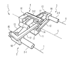
以下、本発明の実施の形態を図面に基づいて説明する。なお、実施の形態を説明するための図において、同一の部材には原則として同一の符号を付し、その繰り返しの説明は省略する。図1は、本実施形態の立体画像撮影装置1の構成を例示する斜視図である。図1を参照すると、立体画像撮影装置1は、右画像撮影ユニット2と、左画像撮影ユニット3と、輻輳角変更ユニット4と、駆動機構の構造が図示されていない基線長変更ユニットを備えている。右画像撮影ユニット2、左画像撮影ユニット3及び輻輳角変更ユニット4は、回転対称軸5を軸に180度回転させたときに、元の状態と同じになるように配置されている。
Hereinafter, embodiments of the present invention will be described with reference to the drawings. Note that components having the same function are denoted by the same reference symbols throughout the drawings for describing the embodiment, and the repetitive description thereof will be omitted. FIG. 1 is a perspective view illustrating the configuration of a stereoscopic
右画像撮影ユニット2は、人の右目に供給される画像を撮像するための装置である。右画像撮影ユニット2は、ズームアップ/ダウン機能を備え、人と被写体との距離の変動に対応する画像を撮像することが可能である。同様に、左画像撮影ユニット3は、人の左目に供給される画像を撮像するための装置である。左画像撮影ユニット3は、右画像撮影ユニット2と連動するズームアップ/ダウン機能を備え、人と被写体との距離の変動に対応する画像を撮像することが可能である。
The right
右画像撮影ユニット2は、被写体からの光を受ける右側対物レンズ2−1と、右側対物レンズ2−1を通った光を結像部(図示されず)に供給する右側結像レンズ2−2とを含んでいる。同様に、左画像撮影ユニット3は、被写体からの光を受ける左側対物レンズ3−1と、左側対物レンズ3−1を通った光を結像部に供給する左側結像レンズ3−2とを含んでいる。
The right
輻輳角変更ユニット4は、右画像撮影ユニット2と左画像撮影ユニット3との輻輳角を変更する機能を備えている。輻輳角変更ユニット4は、中央保持部11と、第1アーム12と、第2アーム13と、第1連結シャフト14と、第2連結シャフト15と、第3連結シャフト16と、対物レンズ支持部材18とを備えている。
The convergence angle changing unit 4 has a function of changing the convergence angle between the right
対物レンズ支持部材18は、右側対物レンズ2−1または左側対物レンズ3−1を保持する。対物レンズ支持部材18は、第2アーム13に沿って直線的に運動することが可能なように構成されている。輻輳角変更ユニット4は、中央保持部11を固定させ、第1連結シャフト14、第2連結シャフト15および第3連結シャフト16を軸に、第1アーム12、第2アーム13を可動させる。対物レンズ支持部材18は、第2アーム13の運動に連動して輻輳角を変更する。
The objective
図1に示されているように、右画像撮影ユニット2側の第1アーム12と左画像撮影ユニット3側の第1アーム12は、第1連結シャフト14で接続されている。第1アーム12と第2アーム13とは、第2連結シャフト15を介して接続されている。右画像撮影ユニット2側の第2アーム13と、左画像撮影ユニット3側の第2アーム13は、第3連結シャフト16を介して接続されている。第1アーム12は、第1連結シャフト14を受ける軸受けを備えている。第1アーム12と第2アーム13とは、第2連結シャフト15を受ける軸受けを備えている。さらに、第2アーム13は、第3連結シャフト16を受ける軸受けを備えている。
As shown in FIG. 1, the
また、中央保持部11には、回転対称軸5に沿って所定の長さを有するシャフト誘導用隙間17が設けられている。第1連結シャフト14は、そのシャフト誘導用隙間17を通っている。第1連結シャフト14は、シャフト誘導用隙間17に沿って前後に直線的に運動することが可能である。中央保持部11に対する第3連結シャフト16の位置を固定し、その中央保持部11に対する第1連結シャフト14の運動を直線運動に制限することで、右画像撮影ユニット2側の第2アーム13と、左画像撮影ユニット3側の第2アーム13とが第3連結シャフト16を軸に、等しい角度で回転運動をする。
Further, the
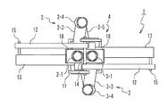
図2は、本実施形態の立体画像撮影装置1を正面から見たときの正面図である。図2に示されているように、立体画像撮影装置1は、中央保持部11を固定したとき、右側対物レンズ2−1の光軸と左側対物レンズ3−1の光軸とを含む平面が、基線長の変化や輻輳角の変化に依存することなく一定である。ここにおいて、右側結像レンズ2−2と左側結像レンズ3−2とは、その平面を挟んで上下に配置される。
FIG. 2 is a front view of the stereoscopic
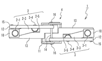
図3は、本実施形態の立体画像撮影装置1を上から見たときの上面図である。図3に示されているように、右側結像レンズ2−2と左側結像レンズ3−2は、上下に重なるように配置されている。また、中央保持部11の2つのシャフト誘導用隙間17は、上から見たときに上下に重なるように形成されている。
FIG. 3 is a top view of the stereoscopic
図4は、本実施形態の立体画像撮影装置1を横から見たときの側面図である。図4に示されているように、右画像撮影ユニット2と左画像撮影ユニット3は、右側対物レンズ2−1の光軸と左側対物レンズ3−1(図示されず)の光軸とを含む平面が、回転対称軸5を含むように配置されている。
FIG. 4 is a side view of the stereoscopic
図5は、本実施形態の立体画像撮影装置1における右画像撮影ユニット2と左画像撮影ユニット3の構成を例示するブロック図である。右画像撮影ユニット2は、第1の光線方向保持部材2−3、第2の光線方向保持部材2−4および第3の光線方向保持部材2−5を備え、それらは右側対物レンズ2−1と右側結像レンズ2−2の間に設けられている。同様に、左画像撮影ユニット3は、第4の光線方向保持部材3−3、第5の光線方向保持部材3−4および第6の光線方向保持部材3−5を備え、それらは、左側対物レンズ3−1と左側結像レンズ3−2の間に設けられている。また、右画像撮影ユニット2は、第1反射鏡21と、第2反射鏡22と、第3反射鏡23と、第4反射鏡24とを備えている。また、左画像撮影ユニット3は、第5反射鏡31と、第6反射鏡32と、第7反射鏡33と、第8反射鏡34とを備えている。
FIG. 5 is a block diagram illustrating the configuration of the right
右側結像レンズ2−2と第1の光線方向保持部材2−3の後には、結像部(CCD)6が配置されている。本実施形態における立体画像撮影装置1は、結像部(CCD)6の構成に制限が無い。例えば、単体のCCDで構成された結像部(CCD)6を用いる場合、複数のCCDで構成された結像部(CCD)6などに生じる、個体差に起因する不具合を解消することができる。
An imaging unit (CCD) 6 is disposed after the right imaging lens 2-2 and the first light beam direction holding member 2-3. In the stereoscopic
また、図5を参照すると、右側対物レンズ2−1は光軸7を有し、左側対物レンズ3−1は光軸8を有している。本実施形態の立体画像撮影装置1において、それらの成す角(輻輳角)と間隔(基線長)とは、上述したように可変である。また、本実施形態の立体画像撮影装置1は、回転対称軸5について回転対称に構成されている。つまり、右画像撮影ユニット2と左画像撮影ユニット3とは、実質的に同じ構成である。したがって以下では、右画像撮影ユニット2に対応して、立体画像撮影装置1の特徴の説明を行う。
Referring to FIG. 5, the right objective lens 2-1 has an
図5に示されているように、第1の光線方向保持部材2−3は、第1反射鏡21と第2反射鏡22との距離を一定に保つ。第2の光線方向保持部材2−4は、第2反射鏡22を含む前部分と、第3反射鏡23を含む後部分とを備えている。その前部分と後部分とは、単一の軸に対し、各々独立に回転可能である。第3の光線方向保持部材2−5は、第3反射鏡23と、第4反射鏡24との距離を一定に保つ。
As shown in FIG. 5, the first light beam direction holding member 2-3 keeps the distance between the first reflecting
第1反射鏡21の反射面と第2反射鏡22の反射面は平行であり、第3反射鏡23の反射面と第4反射鏡24の反射は平行である。第2反射鏡22は、第1反射鏡21から供給される光を、右側対物レンズ2−1の光軸7と平行な方向に反射する。第4反射鏡24は、第3反射鏡23から供給される光を、右側対物レンズ2−1の光軸7と平行な方向に反射する。
The reflecting surface of the first reflecting
図6は、本実施形態の立体画像撮影装置1において、基線長を変更したときの状態を例示する斜視図である。右側対物レンズ2−1は、対物レンズ支持部材18の運動に対応して、第2アーム13に沿って平行移動する。このとき右側対物レンズ2−1は、その光軸に対し回転しながら移動する。また、左側対物レンズ3−1は、対物レンズ支持部材18の運動に対応して、第2アーム13に沿って平行移動する。図6に示されているように、本実施形態の立体画像撮影装置1においては、右側対物レンズ2−1と左側対物レンズ3−1とが接する程度まで基線長を狭くすることができる。
FIG. 6 is a perspective view illustrating a state when the baseline length is changed in the stereoscopic
図7は、基線長を変更した立体画像撮影装置1を前から見たときの正面図である。図7に示されているように、立体画像撮影装置1は、基線長の変更に依存することなく、右側対物レンズ2−1の光軸と左側対物レンズ3−1の光軸とを含む平面が固定となっている。また、右側対物レンズ2−1と左側対物レンズ3−1は連動して可動することが好ましい。そして、各々の光軸がレンズと交差する点から回転対称軸5までの距離は、基線長の半分に等しくなる。
FIG. 7 is a front view when the stereoscopic
図8は、基線長を変更した立体画像撮影装置1を上から見たときの上面図である。図8に示されているように、立体画像撮影装置1の輻輳角変更ユニット4は、基線長の変更に依存することなく輻輳角を保持している。またこのとき、右側結像レンズ2−2と左側結像レンズ3−2は、上下に重なるように配置されたままの状態を維持する。
FIG. 8 is a top view of the stereoscopic
図9は、基線長を変更した立体画像撮影装置1を横から見たときの側面図である。図9に示されているように、右側対物レンズ2−1の光軸と左側対物レンズ3−1(図示されず)の光軸とを含む平面が、回転対称軸5を含むように配置され、基線長の変更に依存することなくその状態が維持されている。
FIG. 9 is a side view of the stereoscopic
図10は、本実施形態の立体画像撮影装置1において、輻輳角を変更したときの状態を例示する斜視図である。対物レンズ支持部材18は、第3連結シャフト16を軸に回転運動する第2アーム13に対応して、回転移動する。右側対物レンズ2−1と左側対物レンズ3−1は、その対物レンズ支持部材18にしたがって回転移動する。このとき対物レンズ支持部材18は、第2アーム13に対する右側対物レンズ2−1の光軸の角度を一定にしたまま回転移動する。また、左側対物レンズ3−1の光軸は、対物レンズ支持部材18の運動に対応して、第2アーム13との角度が一定の状態を維持する。図10に示されているように、本実施形態の立体画像撮影装置1においては、右側対物レンズ2−1と左側対物レンズ3−1との輻輳角は、基線長に依存することなく変更可能である。
FIG. 10 is a perspective view illustrating a state when the convergence angle is changed in the stereoscopic
図11は、輻輳角を変更した立体画像撮影装置1を前から見たときの正面図である。図11に示されているように、立体画像撮影装置1は、輻輳角の変更に依存することなく、右側対物レンズ2−1の光軸と左側対物レンズ3−1の光軸とを含む平面が固定となっている。
FIG. 11 is a front view of the stereoscopic
図12は、輻輳角を変更した立体画像撮影装置1を上から見たときの上面図である。図12に示されているように、立体画像撮影装置1の輻輳角変更ユニット4は、基線長に依存することなく手動又は自動で輻輳角を変更している。またこのとき、右側結像レンズ2−2と左側結像レンズ3−2の光軸と結像部(CCD)6の法線との成す角は、その輻輳角の変化に対応して変化する。輻輳角変更ユニット4は、右側結像レンズ2−2の光軸と結像部(CCD)6との交点、および、左側結像レンズ3−2の光軸と結像部(CCD)6との交点を固定にしたまま、輻輳角を変化させる。
FIG. 12 is a top view when the stereoscopic
図13は、輻輳角を変更した立体画像撮影装置1を横から見たときの側面図である。図13に示されているように、右側対物レンズ2−1の光軸と左側対物レンズ3−1(図示されず)の光軸とを含む平面が、回転対称軸5を含むように配置され、輻輳角の変更に依存することなくその状態が維持されている。
FIG. 13 is a side view of the stereoscopic
上述のように、本実施形態の立体画像撮影装置1は、基線長と輻輳角とを各々独立に制御することが可能である。本実施形態の立体画像撮影装置1は、視点から注視点までの距離を一定にし、かつ、その注視点に存在する被写体に対するピントを固定したときに、基線長と輻輳角とを各々独立に変更させることができる。これによって、立体画像撮影装置1が撮像する立体画像から得られる立体感をユーザの好みに応じて設定することが可能となる。なお、上述のような制御を、コンピュータと連携して実行させても良い。
As described above, the stereoscopic
本実施形態の立体画像撮影装置1の構成を維持しつつ、基線長と輻輳角とを連動させて変えるように構成することも可能である。この場合、本実施形態の立体画像撮影装置1は、基線長と輻輳角との関連が任意に変更可能となる。例えば右画像撮影ユニット2と左画像撮影ユニット3とにズームアップ/ダウン機能が備えられている場合、その倍率に応じて基線長と輻輳角との関連性を設定することで、より適切な立体画像を得ることが可能となる。
While maintaining the configuration of the stereoscopic
本実施形態の立体画像撮影装置1は、右側結像レンズ2−2と左側結像レンズ3−2とが、上下に配置されている。これによって、結像部(CCD)6の上半分で右画像を結像し、結像部(CCD)6の下半分で左画像を結像することができる。現在普及している一般的な画像表示装置は、横長の画像を表示する。そのような画像表示装置に対応した立体画像を撮像する場合に、右側結像レンズ2−2と左側結像レンズ3−2とを本実施形態のように配置することで、結像部(CCD)6の面積を有効に利用することが可能となる。
In the stereoscopic
また、結像レンズ(2−2、3−2)の調整、配置によって、異なる大きさと縦横比のエリアセンサー(6)を、縦または置きにし、上下または左右に2分割して、それぞれ左画像、右画像を結像させることができる。 In addition, the area sensor (6) of different sizes and aspect ratios is vertically or vertically arranged by adjusting and arranging the imaging lenses (2-2, 3-2), and divided into two parts, upper and lower, or left and right, respectively. The right image can be formed.
また、本実施形態の立体画像撮影装置1は、回転対称軸5を軸に回転対称であり、右画像撮影ユニット2を構成する部品と、左画像撮影ユニット3を構成する部品とに差異がない。そのため、立体画像撮影装置1に係るコストを低減させることが可能である。
In addition, the stereoscopic
また、本実施形態の立体画像撮影装置1は、2台のカメラを使用して、それぞれの向きを変えて並べて(Toe inさせて)撮像したときに生じる台形歪が発生することが無い。そのため、撮影レンズの光軸と撮像面の関係を変える機能(例えば、シフト機能やティルト機構)を搭載することなく、適切な立体画像を得ることができる。また、Off Axsisによって画像を撮像する方式に比較して、余分な領域を除去した後、撮影後の画像を重ね合わせ(位置あわせ)をするといった工程を行う必要が無い。そのため、rっ体画像の作成にかかるユーザの労力を、大幅に低減させることが可能となる。
In addition, the stereoscopic
以上、本願発明の実施の形態を具体的に説明した。本願発明は上述の実施の形態に限定されるものではなく、その要旨を逸脱しない範囲で種々変更可能である。 The embodiment of the present invention has been specifically described above. The present invention is not limited to the above-described embodiment, and various modifications can be made without departing from the scope of the invention.
1…立体画像撮影装置
2…右画像撮影ユニット
2−1…右側対物レンズ
2−2…右側結像レンズ
2−3…第1の光線方向保持部材
2−4…第2の光線方向保持部材
2−5…第3の光線方向保持部材
3…左画像撮影ユニット
3−1…左側対物レンズ
3−2…左側結像レンズ
3−3…第4の光線方向保持部材
3−4…第5の光線方向保持部材
3−5…第6の光線方向保持部材
4…輻輳角変更ユニット
5…回転対称軸
6…結像部(CCD)
7…光軸
8…光軸
11…中央保持部
12…第1アーム
13…第2アーム
14…第1連結シャフト
15…第2連結シャフト
16…第3連結シャフト
17…シャフト誘導用隙間
18…対物レンズ支持部材
21…第1反射鏡
22…第2反射鏡
23…第3反射鏡
24…第4反射鏡
31…第5反射鏡
32…第6反射鏡
33…第7反射鏡
34…第8反射鏡
DESCRIPTION OF
DESCRIPTION OF
Claims (11)
前記中央保持部に固定されて、第1領域および第2領域を有する結像部と、 An imaging unit fixed to the central holding unit and having a first region and a second region;
右側対物レンズおよび右側接眼レンズを有し、前記右側対物レンズから受けた第1光を、前記右側接眼レンズを介して前記結像部の前記第1領域に供給する右画像撮像ユニットと、 A right image pickup unit having a right objective lens and a right eyepiece, and supplying the first light received from the right objective lens to the first region of the imaging unit via the right eyepiece;
左側対物レンズおよび左側接眼レンズを有し、前記左側対物レンズから受けた第2光を、前記左側接眼レンズを介して前記結像部の前記第2領域に供給する左画像撮像ユニットと、 A left image pickup unit having a left objective lens and a left eyepiece, and supplying the second light received from the left objective lens to the second region of the imaging unit via the left eyepiece;
前記中央保持部、前記右画像撮像ユニットおよび前記左画像撮像ユニットに接続されて、前記右側対物レンズから前記左側対物レンズまでの基線長を変更する基線長変更ユニットと、 A baseline length changing unit that is connected to the center holding unit, the right image capturing unit, and the left image capturing unit, and changes a baseline length from the right objective lens to the left objective lens;
前記中央保持部、前記右画像撮像ユニットおよび前記左画像撮像ユニットに接続されて、前記右側対物レンズの第1光軸および前記左側対物レンズの第2光軸の間の輻輳角を変更する輻輳角変更ユニットと A convergence angle that is connected to the central holding unit, the right image capturing unit, and the left image capturing unit, and changes a convergence angle between the first optical axis of the right objective lens and the second optical axis of the left objective lens. Change unit and
を具備し、Comprising
前記結像部における前記第1領域および前記第2領域は、同一のCCD(Charge Coupled Device:電荷結合素子 )の表面に設けられている The first region and the second region in the imaging unit are provided on the surface of the same CCD (Charge Coupled Device).
立体画像撮影装置。 Stereoscopic imaging device.
前記基線長変更ユニットは、
前記輻輳角に依存することなく前記基線長を変更し、前記輻輳角変更ユニットが前記輻輳角を変更する際に前記基線長を一定に保つことが可能である
立体画像撮影装置。 The stereoscopic image capturing apparatus according to claim 1 ,
Before Symbol baseline length changing unit,
The change the pre Kimoto line length independent of the angle of convergence, the convergence angle changing unit stereoscopic imaging apparatus can be kept constant the baseline length when changing the convergence angle.
前記右画像撮像ユニットは、前記第1対物レンズと前記第1接眼レンズとの間に配置され、前記第1対物レンズを通った第1光線を反射させて前記第1接眼レンズに供給する右側反射装置群を備え、
前記左画像撮像ユニットは、前記第2対物レンズと前記第2接眼レンズとの間に配置され、前記第2対物レンズを通った第2光線を反射させて前記第2接眼レンズに供給する左側反射装置群を備え、
前記右側反射装置群は、
前記第1光線を、前記第1対物レンズの光軸と前記第2対物レンズの光軸との各々を含む仮想平面と異なる位置に反射させ、
前記左側反射装置群は、
前記第2光線を、前記第1対物レンズの光軸と前記第2対物レンズの光軸との各々を含む仮想平面と異なる位置に反射させる
立体画像撮影装置。 The stereoscopic image capturing apparatus according to claim 2,
The right image pickup unit is disposed between the first objective lens and the first eyepiece, and reflects the first light beam that has passed through the first objective lens and supplies the right eye reflection to the first eyepiece. A device group,
The left image pickup unit is disposed between the second objective lens and the second eyepiece, and reflects the second light beam that has passed through the second objective lens and supplies the second eyepiece to the second eyepiece. A device group,
The right reflection device group includes:
Reflecting the first light beam at a position different from a virtual plane including each of the optical axis of the first objective lens and the optical axis of the second objective lens;
The left reflecting device group is:
A stereoscopic image capturing apparatus that reflects the second light beam at a position different from a virtual plane including each of an optical axis of the first objective lens and an optical axis of the second objective lens.
前記右側反射装置群は、
前記第1光線を前記平面と異なる方向に反射させて第1反射光とする第1反射装置と、
前記第1反射光を前記第1対物レンズの光軸に平行な方向に反射させて第2反射光とする第2反射装置と、
前記第2反射光を反射させて第3反射光とする第3反射装置と、
前記第3反射光を前記第1光軸に平行な方向に反射させて第4反射光として前記第1接眼レンズに供給する第4反射装置とを含み、
前記第1反射装置の反射面と前記第2反射装置の反射面とは互いに平行に配置され、
前記第3反射装置の反射面と前記第4反射装置の反射面とは互いに平行に配置され、
前記第2反射装置の反射面と前記第3反射装置の反射面は、各々の面に交差する軸を共通に回転可能に構成され、
前記左側反射装置群は、
前記第2光線を前記平面と異なる方向に反射させて第5反射光とする第5反射装置と、
前記第5反射光を前記第2対物レンズの光軸に平行な方向に反射させて第6反射光とする第6反射装置と、
前記第6反射光を反射させ第7反射光とする第7反射装置と、
前記第7反射光を前記第2光軸に平行な方向に反射させて第8反射光として前記第2接眼レンズに供給する第8反射装置とを含み、
前記第5反射装置の反射面と前記第6反射装置の反射面とは互いに平行に配置され、
前記第7反射装置の反射面と前記第8反射装置の反射面とは互いに平行に配置され、
前記第6反射装置の反射面と前記第7反射装置の反射面は、各々の面に交差する軸を共通に回転可能に構成される
立体画像撮影装置。 The stereoscopic image capturing apparatus according to claim 3,
The right reflection device group includes:
A first reflecting device that reflects the first light beam in a direction different from the plane to form a first reflected light;
A second reflection device that reflects the first reflected light in a direction parallel to the optical axis of the first objective lens to form second reflected light;
A third reflecting device that reflects the second reflected light to form third reflected light;
A fourth reflection device that reflects the third reflected light in a direction parallel to the first optical axis and supplies the third reflected light to the first eyepiece as fourth reflected light;
The reflective surface of the first reflective device and the reflective surface of the second reflective device are arranged in parallel to each other,
The reflective surface of the third reflective device and the reflective surface of the fourth reflective device are arranged in parallel to each other,
The reflecting surface of the second reflecting device and the reflecting surface of the third reflecting device are configured to be able to rotate in common with an axis intersecting each surface,
The left reflecting device group is:
A fifth reflecting device that reflects the second light beam in a direction different from the plane to form a fifth reflected light;
A sixth reflecting device that reflects the fifth reflected light in a direction parallel to the optical axis of the second objective lens to form a sixth reflected light;
A seventh reflection device that reflects the sixth reflected light to form a seventh reflected light;
An eighth reflecting device that reflects the seventh reflected light in a direction parallel to the second optical axis and supplies the seventh reflected light to the second eyepiece as eighth reflected light;
The reflective surface of the fifth reflective device and the reflective surface of the sixth reflective device are arranged in parallel to each other,
The reflecting surface of the seventh reflecting device and the reflecting surface of the eighth reflecting device are arranged in parallel to each other,
The reflection surface of the sixth reflection device and the reflection surface of the seventh reflection device are configured to be rotatable in common with respect to an axis intersecting each surface.
前記第2反射装置と前記第3反射装置とを結ぶ第1の反射光線経路は、前記第1光軸に対し回転移動し、
前記第1光線の光軸は、
前記第1の反射光線経路の回転移動に対応して平行移動し、
前記第6反射装置と前記第7反射装置とを結ぶ第2の反射光線経路は、前記第2光軸に対し回転移動し、
前記第2光線の光軸は、
前記第2の反射光線経路の回転移動に対応して平行移動する
立体画像撮影装置。 The stereoscopic image capturing apparatus according to claim 4,
A first reflected ray path connecting the second reflecting device and the third reflecting device rotates and moves with respect to the first optical axis;
The optical axis of the first light beam is
Translate in response to rotational movement of the first reflected beam path;
A second reflected ray path connecting the sixth reflecting device and the seventh reflecting device rotates and moves with respect to the second optical axis;
The optical axis of the second light beam is
A stereoscopic image capturing apparatus that translates corresponding to the rotational movement of the second reflected light beam path.
前記第1接眼レンズは、第1光軸を有し、
前記第2接眼レンズは、第2光軸を有し、
前記第1光軸は、第1交点において前記受光面と交差し、
前記第2光軸は、第2交点において前記受光面と交差し、
前記輻輳角変更ユニットは、
前記第1交点と前記第2交点とから等距離に位置し、前記第1対物レンズの光軸と前記第2対物レンズの光軸との各々を含む平面に垂直な線を軸に、前記右画像撮像ユニットと前記左画像撮像ユニットとを回転運動させる
立体画像撮影装置。 The stereoscopic image capturing apparatus according to claim 5,
The first eyepiece has a first optical axis;
The second eyepiece has a second optical axis;
The first optical axis intersects the light receiving surface at a first intersection;
The second optical axis intersects the light receiving surface at a second intersection;
The convergence angle changing unit is:
The right side about a line perpendicular to a plane located at an equal distance from the first intersection and the second intersection and including each of the optical axis of the first objective lens and the optical axis of the second objective lens A three-dimensional image capturing device that rotationally moves an image capturing unit and the left image capturing unit.
前記基線長変更ユニットは、
前記第1対物レンズの光軸と前記第2対物レンズの光軸との各々を含む仮想平面が、前記前記基線長の変化に依存することなく被写体に対し不動となるように、前記第1対物レンズと前記第2対物レンズとを移動させる
立体画像撮影装置。 The stereoscopic image capturing apparatus according to claim 6,
The baseline length changing unit is:
The first objective is such that a virtual plane including each of the optical axis of the first objective lens and the optical axis of the second objective lens is immovable with respect to the subject without depending on the change in the baseline length. A stereoscopic image capturing device for moving a lens and the second objective lens.
前記第1接眼レンズと前記第2接眼レンズの各々は、
前記結像部に備えられた単一の受光部に前記画像を供給する
立体画像撮影装置。 The stereoscopic image capturing apparatus according to claim 7,
Each of the first eyepiece and the second eyepiece is
A stereoscopic image capturing apparatus that supplies the image to a single light receiving unit provided in the imaging unit.
前記基線長変更ユニットは、
前記回転対称軸から前記第1対物レンズまでの距離と、前記回転対称軸から前記第2対物レンズまでの距離とが等しくなるように前記基線長を変更する
立体画像撮影装置。 The stereoscopic image capturing apparatus according to claim 8,
The baseline length changing unit is:
A stereoscopic image capturing apparatus that changes the base length so that a distance from the rotational symmetry axis to the first objective lens is equal to a distance from the rotational symmetry axis to the second objective lens.
前記基線長変更ユニットは、
視点から注視点までの距離と、前記注視点に対するピントとを維持しつつ前記基線長を変更する機能を有し、
前記輻輳角変更ユニットは、
前記視点から前記注視点までの距離と、前記注視点に対するピントとを維持しつつ前記輻輳角を変更する機能を有する
立体画像撮影装置。 The stereoscopic image capturing apparatus according to claim 9,
The baseline length changing unit is:
Having the function of changing the baseline length while maintaining the distance from the viewpoint to the gazing point and the focus on the gazing point,
The convergence angle changing unit is:
A stereoscopic image capturing apparatus having a function of changing the convergence angle while maintaining a distance from the viewpoint to the gazing point and a focus on the gazing point.
前記右画像撮像ユニットと前記左画像撮像ユニットとの各々は、ズームアップ/ダウン機能を備え、
前記基線長変更ユニットは、
前記ズームアップ/ダウン機能によるズームアップ/ダウン動作に連動して前記基線長を変更し、
前記輻輳角変更ユニットは、
前記ズームアップ/ダウン機能によるズームアップ/ダウン動作に連動して前記輻輳角を変更する
立体画像撮影装置。 The stereoscopic image capturing apparatus according to claim 10,
Each of the right image capturing unit and the left image capturing unit has a zoom up / down function,
The baseline length changing unit is:
The baseline length is changed in conjunction with the zoom up / down operation by the zoom up / down function,
The convergence angle changing unit is:
A stereoscopic image capturing apparatus that changes the convergence angle in conjunction with a zoom up / down operation by the zoom up / down function.
Priority Applications (1)
| Application Number | Priority Date | Filing Date | Title |
|---|---|---|---|
| JP2009008189A JP5390865B2 (en) | 2009-01-16 | 2009-01-16 | Stereo imaging device |
Applications Claiming Priority (1)
| Application Number | Priority Date | Filing Date | Title |
|---|---|---|---|
| JP2009008189A JP5390865B2 (en) | 2009-01-16 | 2009-01-16 | Stereo imaging device |
Publications (3)
| Publication Number | Publication Date |
|---|---|
| JP2010164857A JP2010164857A (en) | 2010-07-29 |
| JP2010164857A5 JP2010164857A5 (en) | 2012-03-01 |
| JP5390865B2 true JP5390865B2 (en) | 2014-01-15 |
Family
ID=42581051
Family Applications (1)
| Application Number | Title | Priority Date | Filing Date |
|---|---|---|---|
| JP2009008189A Expired - Fee Related JP5390865B2 (en) | 2009-01-16 | 2009-01-16 | Stereo imaging device |
Country Status (1)
| Country | Link |
|---|---|
| JP (1) | JP5390865B2 (en) |
Families Citing this family (3)
| Publication number | Priority date | Publication date | Assignee | Title |
|---|---|---|---|---|
| JP4654318B1 (en) * | 2010-06-16 | 2011-03-16 | 武蔵オプティカルシステム株式会社 | Optical convergence angle adjusting stereoscopic image capturing apparatus and optical convergence angle adjusting stereoscopic image capturing method |
| US20130170029A1 (en) * | 2010-08-06 | 2013-07-04 | Panasonic Corporation | Lens unit |
| JPWO2016035891A1 (en) * | 2014-09-05 | 2017-05-25 | 株式会社メタ・コーポレーション・ジャパン | Optical adapter and stereoscopic imaging system using the same |
Family Cites Families (8)
| Publication number | Priority date | Publication date | Assignee | Title |
|---|---|---|---|---|
| JPH0446489A (en) * | 1990-06-14 | 1992-02-17 | Nagao Fukuba | Stereoscopic video photographing device |
| JPH07191285A (en) * | 1993-12-27 | 1995-07-28 | Canon Inc | Optical equipment for observation |
| JPH07168098A (en) * | 1993-10-04 | 1995-07-04 | Hiromi Matsushima | Optical system being free of expansion and undulation and optical device |
| JPH11295774A (en) * | 1998-04-08 | 1999-10-29 | Canon Inc | Binoculars equipped with vibration-proof mechanism |
| JP2002072129A (en) * | 2000-08-24 | 2002-03-12 | Olympus Optical Co Ltd | Optical path dividing element and image display device equipped with it |
| JP2003107601A (en) * | 2001-10-01 | 2003-04-09 | Canon Inc | Device and method for photographing three-dimensional image |
| JP2005024629A (en) * | 2003-06-30 | 2005-01-27 | Nippon Hoso Kyokai <Nhk> | Pan head device for stereo camera |
| JP2007206617A (en) * | 2006-02-06 | 2007-08-16 | Fujifilm Corp | Camera |
-
2009
- 2009-01-16 JP JP2009008189A patent/JP5390865B2/en not_active Expired - Fee Related
Also Published As
| Publication number | Publication date |
|---|---|
| JP2010164857A (en) | 2010-07-29 |
Similar Documents
| Publication | Publication Date | Title |
|---|---|---|
| EP2753978B1 (en) | Variable 3-dimensional adaptor assembly for camera | |
| JP5821150B2 (en) | Three-dimensional image capturing method | |
| JP2013025298A (en) | Stereoscopic image pickup device | |
| US7050225B2 (en) | Superimposing microscope having image pickup | |
| US7388719B2 (en) | Camera system | |
| JP2012177747A (en) | Imaging apparatus for stereo image | |
| JP2006525534A (en) | Stereoscopic display | |
| US8639109B2 (en) | Stereoscopic imaging apparatus | |
| JP5390865B2 (en) | Stereo imaging device | |
| JP4727356B2 (en) | Medical stereoscopic observation device | |
| JPH07152096A (en) | Plural-lens image pickup system | |
| EP3797327B1 (en) | A detachable optical structure for displacing the optical axis of a camera device | |
| JP2003107601A (en) | Device and method for photographing three-dimensional image | |
| KR100817881B1 (en) | Three dimensional photographing lens system | |
| JPH08205200A (en) | Three-dimensional image pickup device | |
| JP2015191186A (en) | Stereo adapter and stereo image-capturing device | |
| JP3492921B2 (en) | 3D camera device | |
| JP3609874B2 (en) | Stereoscopic endoscope | |
| JP4217405B2 (en) | Stereo microscope | |
| JP2004070302A (en) | Stereoscopic screen constitution system | |
| US20220007002A1 (en) | Lens apparatus and image pickup apparatus | |
| JP4537079B2 (en) | Binocular magnifier | |
| JP2017106994A (en) | Surgical stereoscopic observation device | |
| KR101815696B1 (en) | Divisional Imaging System | |
| JP2010139909A (en) | Microscope device |
Legal Events
| Date | Code | Title | Description |
|---|---|---|---|
| A521 | Request for written amendment filed |
Free format text: JAPANESE INTERMEDIATE CODE: A523 Effective date: 20120113 |
|
| A621 | Written request for application examination |
Free format text: JAPANESE INTERMEDIATE CODE: A621 Effective date: 20120113 |
|
| A977 | Report on retrieval |
Free format text: JAPANESE INTERMEDIATE CODE: A971007 Effective date: 20130329 |
|
| A131 | Notification of reasons for refusal |
Free format text: JAPANESE INTERMEDIATE CODE: A131 Effective date: 20130501 |
|
| A521 | Request for written amendment filed |
Free format text: JAPANESE INTERMEDIATE CODE: A523 Effective date: 20130628 |
|
| TRDD | Decision of grant or rejection written | ||
| A01 | Written decision to grant a patent or to grant a registration (utility model) |
Free format text: JAPANESE INTERMEDIATE CODE: A01 Effective date: 20130925 |
|
| A61 | First payment of annual fees (during grant procedure) |
Free format text: JAPANESE INTERMEDIATE CODE: A61 Effective date: 20131011 |
|
| R150 | Certificate of patent or registration of utility model |
Ref document number: 5390865 Country of ref document: JP Free format text: JAPANESE INTERMEDIATE CODE: R150 Free format text: JAPANESE INTERMEDIATE CODE: R150 |
|
| R250 | Receipt of annual fees |
Free format text: JAPANESE INTERMEDIATE CODE: R250 |
|
| R250 | Receipt of annual fees |
Free format text: JAPANESE INTERMEDIATE CODE: R250 |
|
| R250 | Receipt of annual fees |
Free format text: JAPANESE INTERMEDIATE CODE: R250 |
|
| R250 | Receipt of annual fees |
Free format text: JAPANESE INTERMEDIATE CODE: R250 |
|
| LAPS | Cancellation because of no payment of annual fees |