JP5386591B2 - Stabilizer bush for vehicle - Google Patents
Stabilizer bush for vehicle Download PDFInfo
- Publication number
- JP5386591B2 JP5386591B2 JP2011534965A JP2011534965A JP5386591B2 JP 5386591 B2 JP5386591 B2 JP 5386591B2 JP 2011534965 A JP2011534965 A JP 2011534965A JP 2011534965 A JP2011534965 A JP 2011534965A JP 5386591 B2 JP5386591 B2 JP 5386591B2
- Authority
- JP
- Japan
- Prior art keywords
- bush
- rubber
- axial direction
- main body
- partition member
- Prior art date
- Legal status (The legal status is an assumption and is not a legal conclusion. Google has not performed a legal analysis and makes no representation as to the accuracy of the status listed.)
- Active
Links
Images


Classifications
-
- B—PERFORMING OPERATIONS; TRANSPORTING
- B60—VEHICLES IN GENERAL
- B60G—VEHICLE SUSPENSION ARRANGEMENTS
- B60G21/00—Interconnection systems for two or more resiliently-suspended wheels, e.g. for stabilising a vehicle body with respect to acceleration, deceleration or centrifugal forces
- B60G21/02—Interconnection systems for two or more resiliently-suspended wheels, e.g. for stabilising a vehicle body with respect to acceleration, deceleration or centrifugal forces permanently interconnected
- B60G21/04—Interconnection systems for two or more resiliently-suspended wheels, e.g. for stabilising a vehicle body with respect to acceleration, deceleration or centrifugal forces permanently interconnected mechanically
- B60G21/05—Interconnection systems for two or more resiliently-suspended wheels, e.g. for stabilising a vehicle body with respect to acceleration, deceleration or centrifugal forces permanently interconnected mechanically between wheels on the same axle but on different sides of the vehicle, i.e. the left and right wheel suspensions being interconnected
- B60G21/055—Stabiliser bars
- B60G21/0551—Mounting means therefor
-
- F—MECHANICAL ENGINEERING; LIGHTING; HEATING; WEAPONS; BLASTING
- F16—ENGINEERING ELEMENTS AND UNITS; GENERAL MEASURES FOR PRODUCING AND MAINTAINING EFFECTIVE FUNCTIONING OF MACHINES OR INSTALLATIONS; THERMAL INSULATION IN GENERAL
- F16F—SPRINGS; SHOCK-ABSORBERS; MEANS FOR DAMPING VIBRATION
- F16F1/00—Springs
- F16F1/36—Springs made of rubber or other material having high internal friction, e.g. thermoplastic elastomers
- F16F1/38—Springs made of rubber or other material having high internal friction, e.g. thermoplastic elastomers with a sleeve of elastic material between a rigid outer sleeve and a rigid inner sleeve or pin, i.e. bushing-type
- F16F1/3842—Method of assembly, production or treatment; Mounting thereof
-
- F—MECHANICAL ENGINEERING; LIGHTING; HEATING; WEAPONS; BLASTING
- F16—ENGINEERING ELEMENTS AND UNITS; GENERAL MEASURES FOR PRODUCING AND MAINTAINING EFFECTIVE FUNCTIONING OF MACHINES OR INSTALLATIONS; THERMAL INSULATION IN GENERAL
- F16F—SPRINGS; SHOCK-ABSORBERS; MEANS FOR DAMPING VIBRATION
- F16F1/00—Springs
- F16F1/36—Springs made of rubber or other material having high internal friction, e.g. thermoplastic elastomers
- F16F1/38—Springs made of rubber or other material having high internal friction, e.g. thermoplastic elastomers with a sleeve of elastic material between a rigid outer sleeve and a rigid inner sleeve or pin, i.e. bushing-type
- F16F1/387—Springs made of rubber or other material having high internal friction, e.g. thermoplastic elastomers with a sleeve of elastic material between a rigid outer sleeve and a rigid inner sleeve or pin, i.e. bushing-type comprising means for modifying the rigidity in particular directions
- F16F1/3876—Springs made of rubber or other material having high internal friction, e.g. thermoplastic elastomers with a sleeve of elastic material between a rigid outer sleeve and a rigid inner sleeve or pin, i.e. bushing-type comprising means for modifying the rigidity in particular directions by means of inserts of more rigid material
-
- B—PERFORMING OPERATIONS; TRANSPORTING
- B60—VEHICLES IN GENERAL
- B60G—VEHICLE SUSPENSION ARRANGEMENTS
- B60G2202/00—Indexing codes relating to the type of spring, damper or actuator
- B60G2202/10—Type of spring
- B60G2202/13—Torsion spring
- B60G2202/135—Stabiliser bar and/or tube
-
- B—PERFORMING OPERATIONS; TRANSPORTING
- B60—VEHICLES IN GENERAL
- B60G—VEHICLE SUSPENSION ARRANGEMENTS
- B60G2204/00—Indexing codes related to suspensions per se or to auxiliary parts
- B60G2204/10—Mounting of suspension elements
- B60G2204/12—Mounting of springs or dampers
- B60G2204/122—Mounting of torsion springs
- B60G2204/1222—Middle mounts of stabiliser on vehicle body or chassis
-
- B—PERFORMING OPERATIONS; TRANSPORTING
- B60—VEHICLES IN GENERAL
- B60G—VEHICLE SUSPENSION ARRANGEMENTS
- B60G2204/00—Indexing codes related to suspensions per se or to auxiliary parts
- B60G2204/40—Auxiliary suspension parts; Adjustment of suspensions
- B60G2204/41—Elastic mounts, e.g. bushings
Description
本発明は、車両用スタビライザブッシュに係り、特に、内孔内にスタビライザバーが非接着で挿通されて、かかるスタビライザバーを車両のボデーに弾性支持させる車両用スタビライザブッシュの改良された構造に関する。 The present invention relates to a vehicle stabilizer bush, and more particularly, to an improved structure of a vehicle stabilizer bush in which a stabilizer bar is inserted in an inner hole in a non-adhesive manner and the stabilizer bar is elastically supported by a vehicle body.
よく知られているように、自動車等の車両には、旋回時等における車体の傾きを抑えるためのスタビライザバーが装着されている。このスタビライザバーは、一般に、スタビライザバーが挿通される内孔を備えた筒状ゴム弾性体からなるブッシュ本体の外周面に、車体に取り付けられる剛性のブラケットが装着されてなるスタビライザブッシュ(防振ブッシュ)を介して、車体に取り付けられる。 As is well known, a vehicle such as an automobile is equipped with a stabilizer bar for suppressing the inclination of the vehicle body when turning. This stabilizer bar is generally a stabilizer bush (an anti-vibration bush) in which a rigid bracket attached to a vehicle body is mounted on the outer peripheral surface of a bush body made of a cylindrical rubber elastic body having an inner hole through which the stabilizer bar is inserted. ) To be attached to the vehicle body.
ところで、スタビライザバーを車体に取り付けるスタビライザブッシュは、よく知られているように、ブッシュ本体の内孔内へのスタビライザバーの挿通状態下で、スタビライザバーの捩り方向での回転(軸心回りの回動)が生じた際に、ブッシュ本体の内周面とスタビライザバーの外周面との間に発生する捩りフリクションが大きいと、異音が発生するだけでなく、乗り心地性能も悪化するといった不具合が惹起される。 By the way, as is well known, the stabilizer bush for attaching the stabilizer bar to the vehicle body rotates in the torsional direction of the stabilizer bar (the rotation around the axis center) with the stabilizer bar inserted into the inner hole of the bush body. When the torsional friction generated between the inner peripheral surface of the bushing body and the outer peripheral surface of the stabilizer bar is large, not only abnormal noise is generated, but also the ride comfort performance deteriorates. Induced.
そこで、従来から、そのようなスタビライザブッシュにおいて、ブッシュ本体とスタビライザバーとの間で生ずる捩りフリクションの低減を図るための構造が、種々提案されている。例えば、実開昭61−134411号公報(特許文献1)等には、筒状ゴム弾性体からなるブッシュ本体の内周面に摺動部材が固着されてなる構造のスタビライザブッシュが、提案されている。そこでは、摺動部材が、例えば、フッ素樹脂繊維を主構成要素として用いた布部材等からなるライナー布にて構成されている。このような構造を有するスタビライザブッシュにあっては、摺動部材の存在により、ブッシュ本体の内周面の摩擦係数が十分に低くされる。それによって、ブッシュ本体の内周面とスタビライザバーの外周面との間の捩りフリクションが、効果的に低減されるようになっている。 Therefore, various structures for reducing torsional friction generated between the bush main body and the stabilizer bar have been conventionally proposed in such a stabilizer bush. For example, Japanese Utility Model Publication No. 61-134411 (Patent Document 1) proposes a stabilizer bush having a structure in which a sliding member is fixed to an inner peripheral surface of a bush main body made of a cylindrical rubber elastic body. Yes. In this case, the sliding member is constituted by, for example, a liner cloth made of a cloth member using a fluororesin fiber as a main constituent element. In the stabilizer bush having such a structure, the friction coefficient of the inner peripheral surface of the bush main body is sufficiently lowered due to the presence of the sliding member. Thereby, the torsional friction between the inner peripheral surface of the bush main body and the outer peripheral surface of the stabilizer bar is effectively reduced.
また、かかる従来のスタビライザブッシュにおいては、ブッシュ本体の軸直角方向中間部に、半割筒状を呈する二つの仕切部材が、ブッシュ本体を、軸直角方向中間部よりも内側に位置する内側ゴム部と外側に位置する外側ゴム部とに仕切るように埋設されている。それら二つの仕切部材は、ブッシュ本体の内孔内へのスタビライザバーの挿通状態下で車両前後方向において互いに対応するように配置されている。これによって、従来のスタビライザブッシュでは、スタビライザバーのブッシュ本体に対する車両前後方向での相対変位によりブッシュ本体に入力される荷重が、各仕切部材にて分散されるようになっている。そして、その結果、かかる荷重の応力集中によりブッシュ本体の一部に過剰な変形が生じたり、ヘタリ等が発生することが、未然に防止され得るようになっている。 Further, in such a conventional stabilizer bush, two partition members having a half-cylindrical shape are formed in the middle portion of the bush body in the direction perpendicular to the axis, and the inner rubber portion in which the bush body is positioned inside the middle portion in the direction perpendicular to the axis. And an outer rubber portion located outside. These two partition members are arranged so as to correspond to each other in the vehicle front-rear direction under the state where the stabilizer bar is inserted into the inner hole of the bush main body. Thereby, in the conventional stabilizer bush, the load input to the bush main body due to the relative displacement of the stabilizer bar in the vehicle front-rear direction with respect to the bush main body is distributed by each partition member. As a result, it is possible to prevent the bush main body from being excessively deformed or sag or the like due to the stress concentration of the load.
ところが、上記の如き構造を有する従来のスタビライザブッシュには、以下のような改良すべき点が存していた。 However, the conventional stabilizer bush having the above-described structure has the following points to be improved.
すなわち、従来のスタビライザブッシュにあっては、一般に、外部からの荷重入力に対する防振特性を、主に、ブッシュ本体の外側ゴム部において発揮させるべく、外側ゴム部のボリュームが可及的に大きくなるように、内側ゴム部が薄肉とされている。それ故、そのようなスタビライザブッシュのブッシュ本体を加硫成形する際には、未加硫ゴムが、外側ゴム部を与える成形キャビティ部分から、各仕切部材の周方向及び軸方向の各端縁部を回り込んで、内側ゴム部を与える、狭幅の成形キャビティ部分内に流入した後、かかる狭幅の成形キャビティ部分内を大きな流動抵抗の下で、比較的に長い距離を流動するようになる。そのため、内側ゴム部を与える成形キャビティ部分への未加硫ゴムの部分的な充填不足が生じて、内側ゴム部の肉厚が不均一となる可能性があった。
That is, in the conventional stabilizer bush, in general, the volume of the outer rubber portion is increased as much as possible in order to exhibit the anti-vibration characteristic against the load input from the outside mainly in the outer rubber portion of the bush body. Thus, the inner rubber part is thin. Therefore, when vulcanizing and molding the bushing body of such a stabilizer bush, the unvulcanized rubber starts from the molding cavity portion that provides the outer rubber portion, and the respective edge portions in the circumferential direction and the axial direction of the partition members. After flowing into the narrow molding cavity portion, which wraps around the inside and gives the inner rubber part, the inside of the narrow molding cavity portion flows under a large flow resistance for a relatively long distance. . Therefore, partial underfilling of unvulcanized硫Go beam into the mold cavity part to provide the inner rubber portion is generated, the wall thickness of the inner rubber portion there is likely to be uneven.
また、そのようなスタビライザブッシュにおいて、摺動部材が表面潤滑性を有するライナー布にて構成される場合には、通常、ブッシュ本体の加硫成形時に、ライナー布が、内側ゴム部に固着されることとなる。そのため、ブッシュ本体の加硫成形時には、上記のように、内側ゴム部を与える、狭幅の成形キャビティ部分内を大きな流動抵抗の下で流動する未加硫ゴムの流動圧によって、ライナー布が部分的に波打った状態、或いは皺が発生した状態で、内側ゴム部に固着される事態や、未加硫ゴムの一部がライナー布の内周面に滲み出して、かかる内周面にゴム膜が形成される事態が生ずる恐れがあった。そして、それらの事態が生じた場合には、ライナー布の周方向において、スタビライザバーに対する摺動性能にバラツキが生じるようになり、その結果、スタビライザバーの捩り方向でのスムーズな回転が阻害されるようになる懸念さえもあったのである。 In such a stabilizer bush, when the sliding member is composed of a liner cloth having surface lubricity, the liner cloth is usually fixed to the inner rubber portion at the time of vulcanization molding of the bush body. It will be. Therefore, at the time of vulcanization molding of the bush body, as described above, the liner cloth is partly caused by the flow pressure of the unvulcanized rubber that flows in the narrow molding cavity portion that gives the inner rubber portion under a large flow resistance. In a state of undulation or wrinkling, a situation where the rubber is fixed to the inner rubber part, or a part of the unvulcanized rubber oozes out to the inner peripheral surface of the liner cloth, and the rubber is applied to the inner peripheral surface. There was a risk that a film would be formed. When such a situation occurs, the sliding performance with respect to the stabilizer bar varies in the circumferential direction of the liner cloth, and as a result, smooth rotation in the twisting direction of the stabilizer bar is hindered. There was even a concern of becoming.
さらに、従来のスタビライザブッシュでは、二つの仕切部材が、ブッシュ本体の軸直角方向中間部に、車両前後方向において互いに対応するように配置されており、ブッシュ本体の上下方向に対応する部位には、仕切部材が、何等存在していない。そのため、そのようなスタビライザブッシュにおいて、摺動部材がライナー布にて構成される場合には、スタビライザブッシュの車両への装着状態下で、上下方向の荷重がスタビライザブッシュに入力したときに、ブッシュ本体の外側ゴム部と内側ゴム部の両方が弾性変形し、それによって、内側ゴム部の内周面に固着されたライナー布に撓みや皺が発生する恐れがあった。そして、そうなった場合にも、ライナー布の周方向において、スタビライザバーに対する摺動性能にバラツキが生じ、それによってスタビライザバーの捩り方向でのスムーズな回転が阻害される可能性があったのである。 Furthermore, in the conventional stabilizer bush, the two partition members are arranged in the middle portion in the direction perpendicular to the axis of the bush main body so as to correspond to each other in the vehicle front-rear direction, and in the portion corresponding to the vertical direction of the bush main body, There is no partition member. Therefore, in such a stabilizer bush, when the sliding member is composed of a liner cloth, when a load in the vertical direction is input to the stabilizer bush with the stabilizer bush mounted on the vehicle, the bush body Both the outer rubber part and the inner rubber part of the inner rubber part were elastically deformed, and there was a possibility that the liner cloth fixed to the inner peripheral surface of the inner rubber part was bent or wrinkled. Even in such a case, the sliding performance with respect to the stabilizer bar varies in the circumferential direction of the liner cloth, and there is a possibility that smooth rotation in the twisting direction of the stabilizer bar may be hindered. .
ここにおいて、本発明は、上述せる如き事情を背景にして為されたものであって、その解決課題とするところは、ブッシュ本体の内周面に固着された摺動部材の構造や種類に拘わらず、ブッシュ本体の内孔内に非接着で挿通されるスタビライザバーの捩り方向でのスムーズな回転が常に安定的に確保され、以て、ブッシュ本体の内周面とスタビライザバーの外周面との間での捩りフリクションが、より効果的に低減され得ると共に、仕切部材の内側に位置する内側ゴム部の肉厚が周方向において均一となる構造が有利に実現され得るように改良されたスタビライザブッシュを提供することにある。 Here, the present invention has been made in the background as described above, and the problem to be solved is related to the structure and type of the sliding member fixed to the inner peripheral surface of the bush body. First, smooth rotation in the torsional direction of the stabilizer bar inserted in the inner hole of the bushing body in a non-adhesive manner is always ensured stably, so that the inner circumferential surface of the bushing body and the outer circumferential surface of the stabilizer bar are secured. Stabilization bush improved so that torsional friction can be reduced more effectively, and a structure in which the thickness of the inner rubber portion located inside the partition member is uniform in the circumferential direction can be advantageously realized Is to provide.
本発明は、上記した課題、又は本明細書全体の記載や図面から把握される課題を解決するために、以下に列挙する各種の態様において、好適に実施され得るものである。また、以下に記載の各態様は、任意の組み合わせにおいても、採用可能である。なお、本発明の態様乃至は技術的特徴は、以下に記載のものに何等限定されることなく、明細書全体の記載並びに図面に開示の発明思想に基づいて、認識され得るものであることが、理解されるべきである。 The present invention can be suitably implemented in various aspects listed below in order to solve the problems described above or the problems grasped from the description and drawings of the entire specification. Moreover, each aspect described below can be employed in any combination. It should be noted that aspects or technical features of the present invention are not limited to those described below, and can be recognized based on the description of the entire specification and the inventive concept disclosed in the drawings. Should be understood.
そして、本発明にあっては、上記した課題の解決のために、(a)軸方向に貫通する内孔を有する筒状のゴム弾性体からなり、該内孔にスタビライザバーが非接着で挿通される一方、外周面に装着されるブラケットを介して車両のボデーに取り付けられるブッシュ本体と、(b)該ブッシュ本体を、内側ゴム部と外側ゴム部とに仕切るように、該ブッシュ本体の軸直角方向中間部に埋設されて、該ブッシュ本体に加硫接着された、剛性を有する半割筒状の二つの仕切部材と、(c)該ブッシュ本体の前記内孔に挿通される前記スタビライザバーと摺接するように、該内孔の内周面に固着された摺動部材とを含んで構成された車両用スタビライザブッシュにおいて、前記ブッシュ本体の前記内側ゴム部の厚さが、前記外側ゴム部の厚さよりも薄く、且つ該内側ゴム部に入力される荷重によって弾性変形しない厚さとされていると共に、前記二つの仕切部材が、該ブッシュ本体の前記内孔への該スタビライザバーの挿通状態下で上下方向に互いに対応位置するように、該ブッシュ本体に埋設されており、更に、該ブッシュ本体を形成する前記ゴム弾性体の射出成形する際の未加硫ゴムが通過可能な貫通孔が、該二つの仕切部材のそれぞれに対して、該仕切部材を周方向と軸方向とにおいてそれぞれ複数に等分する位置のみに形成されており、そして該ブッシュ本体の軸方向両側の端面のうちの少なくとも何れか一方に対して、軸方向外方に突出するゴム凸部が、該ブッシュ本体の軸方向両側端面からの前記突出部の突出高さよりも高い高さを有して一体形成されていると共に、前記外フランジ部が、該ゴム凸部から該ブッシュ本体の軸直角方向外方に突出して、該ブッシュ本体の軸方向両側端面から外部に露出する露出部を含んでいることを特徴とする車両用スタビライザブッシュを、その要旨とするものである。
In the present invention, in order to solve the above-described problems, (a) a cylindrical rubber elastic body having an inner hole penetrating in the axial direction, and a stabilizer bar is inserted into the inner hole without being bonded. On the other hand, a bush body attached to the body of the vehicle via a bracket attached to the outer peripheral surface, and (b) a shaft of the bush body so as to partition the bush body into an inner rubber portion and an outer rubber portion Two rigid half-divided cylindrical partition members embedded in the middle of the right-angle direction and vulcanized and bonded to the bushing body; and (c) the stabilizer bar inserted through the inner hole of the bushing body. A stabilizer bush for a vehicle including a sliding member fixed to the inner peripheral surface of the inner hole so as to be in sliding contact with the inner rubber portion of the bush main body. Thinner than the thickness of And the thickness is such that the two elastic members are not elastically deformed by a load input to the inner rubber part, and the two partition members are vertically aligned with each other in a state where the stabilizer bar is inserted into the inner hole of the bush body. The two partition members are embedded in the bushing body so as to correspond to each other, and further, through holes through which unvulcanized rubber can pass when the rubber elastic body forming the bushing body is injection-molded. Are formed only at positions where the partition member is equally divided into a plurality of portions in the circumferential direction and the axial direction, respectively , and at least one of the end surfaces on both sides in the axial direction of the bush body. The rubber protrusions protruding outward in the axial direction are integrally formed with a height higher than the protruding height of the protrusions from the both axial end surfaces of the bush body, and Nji portion, the rubber protrusion protrudes in the axis-perpendicular direction outwardly of the bushing body, the vehicle stabilizer bushing, characterized in that it includes an exposed portion exposed to the outside from the axial both end faces of the bush body Is the gist of this.
なお、ここで言う「弾性変形しない厚さ」には、弾性変形不能な厚さだけでなく、僅かに弾性変形するものの、その弾性変形量が、有効な防振性能を確保不能か又はその確保が困難な程度の量となる厚さも含まれる。また、「仕切部材を周方向に等分する位置」と「仕切部材を軸方向に等分する位置」には、仕切部材を、正確に同一の寸法で、周方向や軸方向に分割する位置だけでなく、略同一ではあるものの、僅かに異なる寸法(例えば、設計誤差等による微差)で、仕切部材を周方向や軸方向に分割する位置も含まれる。更に、「仕切部材の軸方向」とは、仕切部材が有する半割筒形状の延出方向を言う。以下、同一の意味において使用する。 Note that the “thickness that does not elastically deform” referred to here includes not only a thickness that cannot be elastically deformed, but also a slight elastic deformation, but the amount of elastic deformation does not ensure effective vibration isolation performance or ensure it. Also included is a thickness that is difficult to measure. In addition, “the position where the partition member is equally divided in the circumferential direction” and “the position where the partition member is equally divided in the axial direction” are positions where the partition member is divided into the circumferential direction and the axial direction with exactly the same dimensions. In addition, the position includes a position where the partition member is divided in the circumferential direction and the axial direction with slightly different dimensions (for example, a slight difference due to a design error or the like) although they are substantially the same. Furthermore, the “axial direction of the partition member” refers to the extending direction of the half cylinder shape of the partition member. Hereinafter, they are used in the same meaning.
本発明の好ましい態様の一つによれば、前記ブッシュ本体の前記内側ゴム部の厚さの最大値が、前記外側ゴム部の厚さの最大値の半分に満たない大きさとされる。 According to one of the preferable aspects of the present invention, the maximum value of the thickness of the inner rubber portion of the bush main body is set to be less than half the maximum value of the thickness of the outer rubber portion.
本発明の有利な態様の一つによれば、前記摺動部材が、表面潤滑性を有するライナー布にて構成される。 According to one advantageous aspect of the present invention, the sliding member is composed of a liner cloth having surface lubricity.
本発明の望ましい態様の一つによれば、前記仕切部材が、その軸方向の両端部において、前記ブッシュ本体の軸方向両側の端面から軸方向外方に突出する突出部を有する一方、該ブッシュ本体の軸方向両側の端面のうちの少なくとも何れか一方に対して、軸方向外方に突出するゴム凸部が、該ブッシュ本体の軸方向両側端面からの該突出部の突出高さよりも高い高さを有して一体形成される。 According to a preferred aspect of the present invention, the partition member has projecting portions projecting axially outward from both axial end surfaces of the bushing body at both axial end portions thereof. A rubber convex portion protruding outward in the axial direction with respect to at least one of the end surfaces on both axial sides of the main body is higher than the protruding height of the protruding portions from the both axial end surfaces of the bush main body. And are integrally formed.
本発明の別の有利な態様の一つによれば、前記仕切部材の軸方向両端部における周方向両端側部位に対して、軸直角方向外方に延び出す外フランジ部が、それぞれ一体形成されており、それら各外フランジ部を含んで、前記突出部が構成される。 According to another advantageous aspect of the present invention, outer flange portions extending outward in a direction perpendicular to the axis are integrally formed with respect to the circumferential end portions of the partition member at both axial ends. The projecting portion is configured to include these outer flange portions.
本発明の他の好適な態様の一つによれば、前記外フランジ部が、該ゴム凸部から前記ブッシュ本体の軸直角方向外方に突出して、前記ブッシュ本体の軸方向両側端面から外部に露出する露出部を含んで構成される。 According to another preferred aspect of the present invention, the outer flange portion protrudes outward from the rubber convex portion in a direction perpendicular to the axis of the bushing body, and extends outward from both axial end surfaces of the bushing body. It is configured including an exposed portion that is exposed.
本発明の望ましい別の態様の一つによれば、前記貫通孔が、前記仕切部材の周方向の中央部位における、該仕切部材を軸方向に複数に等分する位置のみに形成される。 According to another desirable aspect of the present invention, the through hole is formed only at a position in the central portion in the circumferential direction of the partition member that equally divides the partition member into a plurality of portions in the axial direction.
本発明の好ましい他の態様の一つによれば、前記貫通孔が、前記仕切部材に対して、該仕切部材を周方向に三等分する位置であって、且つ軸方向において二つ以上に等分する位置のみに形成される。 According to another preferred aspect of the present invention, the through hole is a position that divides the partition member into three equal parts in the circumferential direction with respect to the partition member, and two or more in the axial direction. It is formed only at the position where it is equally divided.
本発明の更に他の望ましい態様の一つによれば、前記仕切部材が、半円に満たない円弧状の軸直角断面形状を有して構成される。 According to still another desirable aspect of the present invention, the partition member is configured to have an arc-shaped cross section perpendicular to the axis that is less than a semicircle.
本発明の別の有利な別の態様の一つによれば、前記ブッシュ本体の内孔への前記スタビライザバーの挿通状態下で上側又は下側に位置する該ブッシュ本体の外周面部分が、軸方向に延びる平坦面部とされると共に、該平坦面部に対して、前記ブラケットが加硫接着される。 According to another advantageous another aspect of the present invention, the outer peripheral surface portion of the bushing body located on the upper side or the lower side under the inserted state of the stabilizer bar into the inner hole of the bushing body is a shaft. The bracket is vulcanized and bonded to the flat surface portion.
本発明の更に別の好適な態様の一つによれば、前記二つの仕切部材の周方向端面同士の間に位置する、前記ブッシュ本体の周上の一箇所に、該ブッシュ本体の外周面から前記内孔に達する切割りが、軸方向の全長に亘って延びるように設けられる。 According to still another preferred aspect of the present invention, the outer peripheral surface of the bushing body is located at one location on the circumference of the bushing body, which is located between the circumferential end surfaces of the two partition members. The slit reaching the inner hole is provided so as to extend over the entire length in the axial direction.
本発明の望ましい更に他の態様の一つによれば、軸方向に延びる分割面を備えた、半割筒状の二つの分割ゴム弾性体が互いに組み付けられて形成される筒状ゴム弾性体にて、前記ブッシュ本体が構成されると共に、前記ブラケットが、該二つの分割ゴム弾性体のうちの一方の分割ゴム弾性体の、前記分割面を除く外周面の全面を包囲する包囲部を有してなり、そして、該ブラケットが、該包囲部により該一方の分割ゴム弾性体を包囲した状態で、該一方の分割ゴム弾性体に加硫接着されることとなる。 According to one of the other desirable aspects of the present invention, a cylindrical rubber elastic body formed by assembling two half-divided cylindrical rubber elastic bodies having a split surface extending in the axial direction. The bush body is configured, and the bracket includes an enclosing portion that surrounds the entire outer peripheral surface of the one divided rubber elastic body excluding the division surface, of the two divided rubber elastic bodies. Then, the bracket is vulcanized and bonded to the one divided rubber elastic body in a state where the one divided rubber elastic body is surrounded by the surrounding portion.
すなわち、本発明に従う車両用スタビライザブッシュにあっては、半割筒状の二つの仕切部材が、ブッシュ本体の軸方向中間部に、車両上下において対応位置するように埋設されていると共に、薄肉の内側ゴム部が、入力荷重、とりわけ軸直角方向に入力される荷重に対して弾性変形しないようになっている。それ故、かかるスタビライザブッシュでは、車両への装着状態下で、ブッシュ本体に上下方向の荷重が入力したときに、内側ゴム部が弾性変形することがない。そのため、内側ゴム部(内孔)の内周面に固着された摺動部材が表面潤滑性を有する布部材等からなるライナー布であっても、かかるライナー布が、内側ゴム部の弾性変形によって撓んだり、或いは皺が発生したりすることが、効果的に皆無とされ得る。そして、それによって、従来のスタビライザブッシュとは異なり、ブッシュ本体への上下方向の荷重入力時に、ライナー布からなる摺動部材の周方向において、スタビライザバーに対する摺動性能にバラツキが生ずる恐れがなく、スタビライザバーの捩り方向でのスムーズな回転が、常に安定的に確保され得る。 That is, in the stabilizer bush for a vehicle according to the present invention, the two half-divided cylindrical partition members are embedded in the axially intermediate portion of the bushing body so as to correspond to the upper and lower sides of the vehicle, and are thin. The inner rubber portion is not elastically deformed against an input load, particularly a load input in a direction perpendicular to the axis. Therefore, in such a stabilizer bush, the inner rubber portion does not elastically deform when a load in the vertical direction is input to the bush main body in a mounted state on the vehicle. Therefore, even if the sliding member fixed to the inner peripheral surface of the inner rubber part (inner hole) is a liner cloth made of a cloth member having surface lubricity, the liner cloth is caused by elastic deformation of the inner rubber part. It is possible to effectively eliminate bending or wrinkling. And, unlike conventional stabilizer bushes, there is no risk of variation in the sliding performance with respect to the stabilizer bar in the circumferential direction of the sliding member made of the liner cloth when the vertical load is applied to the bush body. Smooth rotation in the twisting direction of the stabilizer bar can always be ensured stably.
また、本発明に従う車両用スタビライザブッシュにおいては、未加硫ゴムが通過可能な貫通孔が、各仕切部材に対して、それを周方向と軸方向とにおいてそれぞれ複数に等分する位置のみに形成されている。このため、例えば、射出成形により、ブッシュ本体を加硫成形する際に、内側ゴム部を与える成形キャビティ部分内に充填されるべき未加硫ゴムの一部が、外側ゴム部を与える成形キャビティ部分から、各仕切部材の周方向及び軸方向の各端縁部を回り込んで、内側ゴム部を与える成形キャビティ部分内に流入する一方、別の一部の未加硫ゴムが、外側ゴム部を与える成形キャビティ部分から、各仕切部材に設けられた貫通孔を通じて、内側ゴム部を与える成形キャビティ部分内に流入するようになる。このとき、内側ゴム部を与える成形キャビティ部分内での未加硫ゴムの流れが、従来のスタビライザブッシュのブッシュ本体を一体加硫成形する場合とは異なった流動状態となる。
Further, in the vehicle stabilizer bush according to the present invention, the through-hole through which the unvulcanized rubber can pass is formed only at a position where each partition member is equally divided into a plurality of portions in the circumferential direction and the axial direction. Has been. For this reason, for example, when the bushing body is vulcanized by injection molding, a part of the unvulcanized rubber to be filled in the molding cavity part that gives the inner rubber part gives the outer rubber part. From each of the circumferential edges and the axial ends of each partition member, it flows into the molding cavity portion that gives the inner rubber portion, while another part of the unvulcanized rubber wraps the outer rubber portion. From the molding cavity portion to be fed, the gas flows into the molding cavity portion to which the inner rubber portion is fed through the through hole provided in each partition member. At this time, the flow of the unvulcanized rubber in the molding cavity portion that provides the inner rubber portion is in a different flow state from the case where the bush body of the conventional stabilizer bush is integrally vulcanized.
すなわち、内側ゴム部を与える成形キャビティ部分内に充填されるべき未加硫ゴムの全部が、各仕切部材の周方向及び軸方向の各端縁部を回り込んで、内側ゴム部を与える成形キャビティ部分内に流入する場合に比して、内側ゴム部を与える成形キャビティ部分内での未加硫ゴムの周方向や軸方向の流動距離が小さくなる。しかも、各仕切部材の周方向及び軸方向の各端縁部を回り込んで、内側ゴム部を与える成形キャビティ部分内に流入した一部の未加硫ゴムの周方向の流動距離及び軸方向の流動距離と、各仕切部材に設けられた貫通孔を通じて、内側ゴム部を与える成形キャビティ部分内に流入した、別の一部の未加硫ゴムの周方向の流動距離及び軸方向の流動距離とが、互いに略同一の大きさとされる。
That is, all of the unvulcanized rubber to be filled in the molding cavity portion that gives the inner rubber portion wraps around the circumferential edge and the axial end edge of each partition member to give the inner rubber portion Compared to the case of flowing into the portion, the flow distance in the circumferential direction and the axial direction of the unvulcanized rubber in the molding cavity portion that provides the inner rubber portion is reduced. Moreover, the circumferential flow distance and axial flow of some of the unvulcanized rubber that has flowed into the molding cavity portion that feeds the inner rubber portion around the circumferential edge and the axial edge of each partition member. The flow distance and the flow distance in the circumferential direction and the flow distance in the axial direction of another part of the unvulcanized rubber that has flowed into the molding cavity portion that gives the inner rubber portion through the through holes provided in each partition member Are substantially the same size.
それ故、本発明に従う車両用スタビライザブッシュでは、ブッシュ本体の加硫成形時において、内側ゴム部を与える成形キャビティ部分への未加硫ゴムの部分的な充填不足が生じて、内側ゴム部の肉厚が不均一となることが、効果的に回避され得る。また、摺動部材が、布部材等からなるライナー布にて構成される場合にあっても、ブッシュ本体の加硫成形時に、内側ゴム部を与える成形キャビティ部分内を流動する未加硫ゴムの流動圧に基づいて摺動部材に加えられる圧力が、有利に低減され得ると共に、摺動部材の外周面の全面において効果的に均一化され得る。それによって、内側ゴム部が薄肉であるために、かかる内側ゴム部を与える成形キャビティ部分が狭幅とされているにも拘わらず、ブッシュ本体の加硫成形時に、摺動部材が、未加硫ゴムの流動圧によって部分的に波打った状態、或いは皺が発生した状態で、内側ゴム部に固着される事態や、未加硫ゴムの一部が摺動部材の内周面に滲み出して、かかる内周面にゴム膜が形成される事態が生ずることが、効果的に解消され得る。その結果、摺動部材の波打ちや皺、或いは摺動部材の内周面のゴム膜等に起因して、摺動部材の周方向において、スタビライザバーに対する摺動性能にバラツキが生ずるといった懸念が完全に払拭されて、スタビライザバーの捩り方向でのスムーズな回転が、常時、安定的に確保され得る。
Therefore, the vehicle stabilizer bushing according to the present invention, at the time of vulcanization molding of the bushing body, partially filling shortage of unvulcanized硫Go beam into the mold cavity part to provide the inner rubber portion is generated, the inner rubber portion The uneven thickness can be effectively avoided. Further, even when the sliding member is composed of a liner cloth made of a cloth member or the like, the unvulcanized rubber that flows in the molding cavity portion that provides the inner rubber portion at the time of vulcanization molding of the bush main body. The pressure applied to the sliding member based on the fluid pressure can be advantageously reduced and can be effectively equalized over the entire outer peripheral surface of the sliding member. Thereby, since the inner rubber part is thin, the sliding member is not vulcanized during the vulcanization molding of the bushing body even though the molding cavity part that gives the inner rubber part is narrow. When the rubber is partially undulated by the flow pressure of the rubber or when wrinkles are generated, the rubber is stuck to the inner rubber part, or a part of the unvulcanized rubber oozes out on the inner peripheral surface of the sliding member. The occurrence of a situation where a rubber film is formed on the inner peripheral surface can be effectively eliminated. As a result, there is a complete concern that the sliding performance with respect to the stabilizer bar may vary in the circumferential direction of the sliding member due to the waviness or wrinkles of the sliding member or the rubber film on the inner peripheral surface of the sliding member. Thus, smooth rotation in the twisting direction of the stabilizer bar can be always ensured stably.
従って、かくの如き本発明に従う車両用スタビライザブッシュにあっては、仕切部材の内側に位置する内側ゴム部の肉厚が周方向において均一とされて、摺動部材の内側ゴム部に対する固着力と良好な防振性能とが安定的に確保され得る。また、ブッシュ本体の内孔の内周面に固着された摺動部材の構造に拘わらず、ブッシュ本体の内周面とスタビライザバーの外周面との間での捩りフリクションが、より効果的に且つ安定的に低減され得る。そして、その結果として、スタビライザバーの捩り方向への回転に起因した異音の発生が、より有利に防止され得ると共に、良好な乗り心地性能が有効に確保され得るのである。 Therefore, in the vehicle stabilizer bush according to the present invention as described above, the wall thickness of the inner rubber portion located inside the partition member is uniform in the circumferential direction, and the fixing force of the sliding member to the inner rubber portion is Good vibration-proof performance can be secured stably. In addition, the torsional friction between the inner peripheral surface of the bush main body and the outer peripheral surface of the stabilizer bar is more effective regardless of the structure of the sliding member fixed to the inner peripheral surface of the inner hole of the bush main body. It can be stably reduced. As a result, the generation of noise due to the rotation of the stabilizer bar in the torsional direction can be prevented more advantageously, and good riding comfort performance can be effectively ensured.
加えて、本発明に従う車両用スタビライザブッシュにおいては、二つの仕切部材が、ブッシュ本体の軸方向中間部に埋設されて、内側ゴム部が軸直角方向の入力荷重に対して弾性変形しないようになっている。そのため、ブッシュ本体全体としてのばねの荷重−撓み特性におけるヒステリシスが効果的に小さくされ得る。これによって、本発明に係るスタビライザブッシュが装着される車両の操縦安定性が効果的に高められ得ることとなる。 In addition, in the vehicle stabilizer bush according to the present invention, the two partition members are embedded in the intermediate portion in the axial direction of the bush body, so that the inner rubber portion does not elastically deform with respect to the input load perpendicular to the axial direction. ing. Therefore, the hysteresis in the load-deflection characteristic of the spring as the whole bush body can be effectively reduced. Thereby, the steering stability of the vehicle to which the stabilizer bush according to the present invention is mounted can be effectively enhanced.
以下、本発明を更に具体的に明らかにするために、本発明の構成について、図面を参照しつつ、詳細に説明することとする。 Hereinafter, in order to clarify the present invention more specifically, the configuration of the present invention will be described in detail with reference to the drawings.
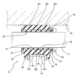
先ず、図1及び図2には、本発明に従う車両用スタビライザブッシュの一実施形態としての自動車用スタビライザブッシュが、自動車に取り付けられた状態での軸直角方向断面形態と軸方向断面形態とにおいて、それぞれ示されている。それらの図から明らかなように、スタビライザブッシュ10は、自動車のスタビライザバー12に装着されて、かかるスタビライザバー12を自動車のボデー14に対して弾性的に支持させるものである。そして、このスタビライザブッシュ10は、ゴム弾性体からなるブッシュ本体16を有してている。
First, in FIG.1 and FIG.2, the stabilizer bush for motor vehicles as one Embodiment of the stabilizer bush for vehicles according to this invention in the state orthogonal to an axial cross section in the state attached to the motor vehicle, and an axial cross section, Each is shown. As is clear from these figures, the
より詳細には、ブッシュ本体16は、図3及び図4に示されるように、全体として、軸方向に延びる内孔18を備えた筒形状を有している。そして、その外周面のうち、図3の下側に位置する外周面部分(以下、下面と言う)が略半割円筒面とされている一方、図3の左右両側に位置する二つの外周面部分(以下、側面と言う)と図3の上側に位置する外周面部分(以下、上面と言う)とが、それぞれ矩形状の平坦面とされている。
More specifically, as shown in FIGS. 3 and 4, the bush
ブッシュ本体16の軸方向両側の端部には、その上面を除く外周面部分に対して、比較的に厚肉の突条20,20が、側面を互いに対向配置させた状態で、それぞれ、一体的に周設されている。それら各突条20,20は、略逆U字形の平板形態を有している。また、ブッシュ本体16の軸方向両側の端面には、軸方向外方に突出するゴム凸部22が、それぞれ一体形成されている。このゴム凸部22は、ブッシュ本体16の軸方向両側端面にそれぞれ開口する内孔18の各開口部の周りにおいて、それら各開口部の周方向に延びる円環板形状を有している。かかるゴム凸部22の幅は、各端面の外周部の全周にゴム凸部22の非形成部位を存在させ得る幅とされている。また、ゴム凸部22は、周方向に等間隔をおいた四箇所の部位が、幅広とされている。
The ends of the
ブッシュ本体16の周上の一箇所、具体的には、二つの側面のうちの一方の側面におけるブッシュ本体16の高さ方向(図3の上下方向)の中間部には、内孔18に達する切割り24が、軸方向の全長に亘って延びるように形成されている。なお、この切割り24によって、ブッシュ本体16の軸方向両側端面にそれぞれ一体形成された前記ゴム凸部22,22も、その周上の一箇所において切断されている。これによって、図3に二点鎖線で示されるように、ブッシュ本体16が、切割り24の形成部位とは反対側部分を中心として、内孔18を側方に向かって拡開するように回動可能とされている。
An
図1乃至図4から明らかなように、ブッシュ本体16の内部には、二つの仕切部材26,26が、埋設されている。それら二つの仕切部材26,26は、互いに同じ大きさで同一の形状を有している。そして、ここでは、そのような二つの仕切部材26,26が、ブッシュ本体16に対して加硫接着されている。
As apparent from FIGS. 1 to 4, two
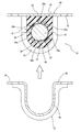
より詳細には、仕切部材26は、図5及び図6に示されるように、軸直角方向断面が半円に満たない円弧形状とされた分割筒金具からなっている。そして、ブッシュ本体16よりも十分に薄い厚さを有している(図1参照)。また、仕切部材26の軸方向(延出方向)長さは、ブッシュ本体16の軸方向長さ(軸方向両側の端面間の長さ)よりも長く、且つブッシュ本体16の軸方向両側端面に突設されたゴム凸部22,22の先端面間の長さよりも短くされている(図2及び図4参照)。更に、仕切部材26は、その内径が、筒状のブッシュ本体16の内径よりも少しだけ大きくされている一方、その外径が、ブッシュ本体16の半割円筒状を呈する下面部分の径よりも十分に小さくされている。そして、仕切部材26の内径とブッシュ本体16の内径との差が、仕切部材26の外径とブッシュ本体16の下面部分の径との差よりも十分に小さくされている(図1及び図2参照)。
More specifically, as shown in FIGS. 5 and 6, the
このような仕切部材26の周方向の両側端部には、それら両側端部を屈曲してなる屈曲部28a,28bが、それぞれ一体形成されている。各屈曲部28a,28bは、仕切部材26の周方向の両側端部から、径方向外方に所定高さで突出し、且つ軸方向に連続して延びる平板形態を呈している。また、そのような各屈曲部28a,28bの延出方向(仕切部材26の軸方向)の中間部には、矩形の切欠部30が、各々形成されている。これによって、各屈曲部28a,28bの延出方向両側の端部が、延出方向中間部よりも広幅とされている。そして、この各屈曲部28a,28b延出方向両端の幅広部分が、仕切部材26の軸方向両端部における周方向両側部位に対して、軸直角方向外方に延び出す外フランジ部32a,32a,32b,32bとされている。
また、仕切部材26には、それを厚さ方向に貫通する3個の貫通孔36a,36b,36cが設けられている。それら3個の貫通孔36a,36b,36cは、何れも、円形形状を呈し、仕切部材26のブッシュ本体16に対する加硫接着時、つまり、ブッシュ本体16と仕切部材26との一体加硫成形時において、未加硫ゴムが通過するのに十分な大きさを有している。なお、それら各貫通孔36a,36b,36cの具体的な大きさ(開口面積や内径等)は、ブッシュ本体16の全体の大きさや、仕切部材26に対する貫通孔36の形成個数、或いは後述する内側ゴム部(38)の厚さ等に応じて、適宜に決定されるものである。
The
そして、本実施形態では、特に、そのような貫通孔36a,36b,36cが、仕切部材26の周方向の中央部において仕切部材26を軸方向に四等分する箇所だけに、それぞれ形成されている。
In the present embodiment, in particular, such through
すなわち、図5に示されるように、仕切部材26の軸方向一方側(図5の上側)の端縁とそれに直近の貫通孔36aの内周面との間の軸方向長さ(距離):L1 と、仕切部材26の軸方向一方側において互いに隣り合う2個の貫通孔36a,36bの各内周面間の軸方向長さ(距離):L2 と、仕切部材26の軸方向他方側(図5の下側)において互いに隣り合う2個の貫通孔36b,36cの各内周面間の軸方向長さ(距離):L3 と、仕切部材26の軸方向他方側の端縁とそれに直近の貫通孔36cの内周面との間の軸方向長さ(距離):L4 とが、全て同一の大きさとされている。That is, as shown in FIG. 5, the axial length (distance) between the edge on one axial side of the partition member 26 (upper side in FIG. 5) and the inner peripheral surface of the through
また、図6に示されるように、仕切部材26の周方向一方側(図6の右側)の端縁から貫通孔36bの内周面までの周方向長さ:M1 と、仕切部材26の周方向他方側(図6の左側)の端縁から貫通孔36bの内周面までの周方向長さ:M2 とが、同一の大きさとされている。また、図5から明らかなように、残りの二つの貫通孔36a,36cについても、仕切部材26の周方向両側端縁から各貫通孔36a,36cの内周面までの周方向長さが、全て同一の大きさとされている。Further, as shown in FIG. 6, the circumferential length M 1 from the edge on the one side in the circumferential direction of the partition member 26 (the right side in FIG. 6) to the inner peripheral surface of the through
なお、貫通孔36a,36b,36c同士の間の軸方向長さ:L2 ,L3 と、仕切部材26の軸方向端縁とそれに直近の貫通孔36a,36cとの間の軸方向長さ:L1 ,L4 は、それらの全てが必ずしも完全に同一とされていなくとも良い。それらのうちの少なくとも一つの軸方向長さが異なっていても、その違いが微差であると判断できる程度のものであれば、許容され得る。また、仕切部材26の周方向両側端縁から各貫通孔36a,36b,36cまでの周方向長さ:M1 ,M2 も、必ずしも完全に同一とされていなくとも良い。それらの周方向長さが異なっていても、その違いが微差であると判断できる程度のものであれば、許容され得る。Note that the axial lengths between the through
そして、図1及び図2に示されるように、上記の如き構造とされた二つの仕切部材26,26が、ブッシュ本体16の軸直角方向中間部に、内孔18を間に挟んで、それぞれの内周面を内側に配置し、且つ上下方向において互いに対応位置させられた状態で、埋設されている。つまり、二つの仕切部材26,26が、内孔18と同軸的に延びる筒状金具を形成するようにして、ブッシュ本体16内に埋設されている。これにより、ブッシュ本体16が、二つの仕切部材26,26にて、それらよりも内側に位置する内側ゴム部38と、それらよりも外側に位置する外側ゴム部40とに仕切られている。そして、各仕切部材26,26が、その内周面において、内側ゴム部38に加硫接着されている一方、その外周面において、外側ゴム部40に加硫接着されているのである。
As shown in FIGS. 1 and 2, the two
また、上述のように、各仕切部材26,26の内径とブッシュ本体16の内径との差が、各仕切部材26,26の外径とブッシュ本体16の下面部分の径との差よりも十分に小さくされている。これにより、内側ゴム部38が、外側ゴム部40よりも十分に薄肉とされている。
Further, as described above, the difference between the inner diameter of each
そして、本実施形態では、特に、スタビライザブッシュ10の自動車への装着状態下でのブッシュ本体16の軸直角方向への荷重の入力時に、内側ゴム部38が弾性変形しないように、内側ゴム部38の厚さが極めて薄い厚さに設定されている。
In the present embodiment, the
すなわち、後述する如く、ブッシュ本体16の内孔18内にスタビライザバー12が挿通されて、自動車のボデー14に取り付けられた状態下では、スタビライザバー12が、ブッシュ本体16に対して、その軸直角方向(内側ゴム部38や外側ゴム部40の厚さ方向)に相対変位したときに、内側ゴム部38に対して所定の荷重が入力される。その際、内側ゴム部38は、十分に薄肉とされているために、厚さ方向(軸直角方向)において弾性変形しないようになっているのである。
That is, as will be described later, when the
なお、そのような内側ゴム部38の厚さは、特に限定されるものではなく、ブッシュ本体16の全体の大きさや、スタビライザブッシュ10の自動車への装着状態下でのブッシュ本体16への入力荷重の大きさ等に応じて、適宜に決定される。そして、好適には、内側ゴム部38の最大厚さ(図1にT1 にて示される寸法)が、外側ゴム部40の最大厚さ(内孔18の径方向に沿った厚さのうちの最大のもので、図1にT2 にて示される寸法)の半分に満たない寸法となるように、つまり、T1 <T2 /2の関係式を満たすように、内側ゴム部38の厚さが設定される。これによって、ブッシュ本体16に対する軸直角方向への荷重入力時に、外側ゴム部40が厚さ方向において確実に弾性変形して、外側ゴム部40により有効な防振性能が発揮され得る一方、内側ゴム部38が、厚さ方向において弾性変形しないか又はその弾性変形が効果的に抑制され得るようになる。そして、後述するように、内側ゴム部38の内周面には、ライナー布42が、例えば内側ゴム部38のゴム材料によるアンカー効果等により固着される。そのため、内側ゴム部38の厚さは、少なくともライナー布42を固着可能な厚さとされている必要がある。その点からして、内側ゴム部38は、1mm以上の厚さを有していることが望ましい。
The thickness of the
また、本実施形態では、上記の如きブッシュ本体16内への二つの仕切部材26,26の埋設状態下で、一方の仕切部材26が、3個の貫通孔36a,36b,36cを、ブッシュ本体16の半割円筒面からなる下面の周方向中心部に対して、ブッシュ本体16の高さ方向において対応位置させるように、配置されている。他方の仕切部材26は、3個の36a,36b,36cを、ブッシュ本体16の矩形の平坦面からなる上面の幅方向中心部に対して、ブッシュ本体16の高さ方向において対応位置させるように配置されている。
Further, in the present embodiment, under the state in which the two
さらに、各仕切部材26,26の周方向両端部にそれぞれ一体的に屈曲形成された屈曲部28a,28bが、ブッシュ本体16の高さ方向の中間部分を介して対向配置されている。そして、互いに対向配置された一方の仕切部材26の屈曲部28bと他方の仕切部材26の屈曲部28bとの間に位置する、ブッシュ本体16の高さ方向中間部分(内側ゴム部38部分と外側ゴム部40部分)に、前記切割り24が形成されている。これによって、ブッシュ本体16の切割り24での拡開が、ブッシュ本体16に埋設された二つの仕切部材26,26に邪魔されることなく、スムーズに実施され得るようになっている。
Further,
なお、ここでは、各仕切部材26,26の横断面形状(軸直角断面形状)が、半円に満たない円弧形状とされて、各仕切部材26,26の周方向長さが短くなるように設定されている。これにより、各仕切部材26,26の互いに対応する屈曲部28a,28a間や屈曲部28b,28b間の距離が比較的に大きくされて、それら屈曲部28a,28a間や屈曲部28b,28b間にそれぞれ位置する、ブッシュ本体16の高さ方向中間部分のボリュームも十分な大きさとされている。その結果として、ブッシュ本体16の高さ方向中間部分に対する切割り24の形成が容易となっていると共に、切割り24の形成部位とは反対側に位置するブッシュ本体16の高さ方向中間部分が、ヒンジ部として確実に機能し得るようになっている。
Here, the cross-sectional shape (cross-sectional shape perpendicular to the axis) of each
また、図3及び図4に示される如く、二つの仕切部材26,26のブッシュ本体16内への埋設状態下で、ブッシュ本体16の軸方向両側端面から突出した各仕切部材26,26の軸方向両側端部と外フランジ部32a,32a,32b,32bの基部とが、前記ゴム凸部22,22内に埋入されている。そして、各外フランジ部32a,32a,32b,32bの先端部のうち、ブッシュ本体16の軸方向外方に位置する角部部位のみが、ブッシュ本体16の径方向外方に向かって、ゴム凸部22,22から突出して、ブッシュ本体16の軸方向両側端面から外部に露出している。これにより、ここでは、ブッシュ本体16の軸方向両側端面から露出する各外フランジ部32a,32a,32b,32bの先端側角部部位が、露出部34a,34a,34b,34bとされている。そして、それら各露出部34a,34a,34b,34bが、後述するブッシュ本体16と各仕切部材26,26との一体加硫成形時において、各仕切部材26,26を所定位置に位置決めするために、入れ子型等にて保持されるべき部分となっているのである。このことから明らかなように、本実施形態では、仕切部材の軸方向両端部に設けられた突出部が、各仕切部材26,26の軸方向両端部と外フランジ部32a,32a,32b,32bとにて構成されている。なお、露出部34a,34a,34b,34bを、外フランジ部32a,32a,32b,32bの先端側角部部位だけでなく、外フランジ部32a,32a,32b,32bの全体にて構成しても良い。
Further, as shown in FIGS. 3 and 4, the shafts of the
また、図1及び図2に示されるように、ブッシュ本体16の内側ゴム部38の内周面には、ライナー布42が固着されている。このライナー布42は、内側ゴム部38の内径に対応した外径と、ブッシュ本体16の軸方向両側端面にそれぞれ一体形成された円環板状のゴム凸部22,22の先端面間の距離と同じ軸方向長さとを有する薄肉の円筒形状を呈し、内側ゴム部38の内周面の全面とゴム凸部22の内周面の全面を被覆している。これにより、内側ゴム部38の内周面の全面に対して十分な摺動性が付与されている。そうして、ブッシュ本体16の内孔18内にスタビライザバー12が挿入された状態下において、スタビライザバー12が、ブッシュ本体16の内側ゴム部38に対してスムーズに相対回転し得るようになっている。
As shown in FIGS. 1 and 2, a
なお、ライナー布42は、表面潤滑性を有するものであれば、その種類が特に限定されるものではない。このライナー布42として使用可能なものには、例えば、テフロン(登録商標)布等のフッ素樹脂繊維を主要構成部材とするフッ素樹脂系布材やポリアミド繊維からなる編成物等が挙げられる。
The type of the
そして、上述の如き構造とされたブッシュ本体16が、ブラケット44を介して、自動車のボデー14に取り付けられている。即ち、スタビライザバー12を挿通したブッシュ本体16の平坦な上面が、ボデー14の取付面に接触させられる。また、ブッシュ本体16の軸方向中間部が、ブラケット44の包囲部46にて包囲された状態で、包囲部46の周方向両端から延びる二つの取付部48,48がボデー14にボルト固定される。そうして、スタビライザブッシュ10が、ボデー14に装着されている。これにより、スタビライザバー12が、スタビライザブッシュ10を介して、水平方向に延びる状態で、ボデー14に防振支持されるようになっている。そして、スタビライザバー12とブッシュ本体16との間で、上下方向や水平方向での相対変位に伴って生ずる振動荷重が、ブッシュ本体16の外側ゴム部40の弾性変形に基づいて、効果的に吸収されるようになっているのである。
The bush
また、図2に示されるように、ここでは、スタビライザブッシュ10のボデー14への取付状態下で、ブッシュ本体16の軸方向一方側の端面に一体形成されたゴム凸部22の先端面が、スタビライザバー12に外嵌固定されたリング状のストッパ金具49の端面に対して、僅かな距離を隔てて対向配置されるようになっている。
Further, as shown in FIG. 2, here, the end surface of the rubber
前記したように、ゴム凸部22,22は、ブッシュ本体16の軸方向両側端面から、仕切部材26,26の軸方向両端部と各外フランジ部32a,32bの突出高さよりも高い高さで、軸方向外方に突出している。即ち、ゴム凸部22,22が、各外フランジ部32a,32bの露出部34a,34bを除く部分と仕切部材26,26の軸方向両端部とを被覆している。そして、スタビライザバー12のブッシュ本体16に対する軸方向一方側(図2の右側)への相対変位時に、かかる軸方向一方側に位置するゴム凸部22が、ストッパ金具49に対して、外フランジ部32a,32bの露出部34a,34bよりも先に当接するようになっている。これにより、ゴム凸部22が、仕切部材26,26の軸方向端部及び外フランジ部32a,32bとストッパ金具49との接触乃至は当接を阻止する緩衝ゴム部として有利に機能し得るように構成されているのである。なお、ここでは、スタビライザバー12が、ブッシュ本体16の軸方向他方側に延び出す部分において屈曲していることで、スタビライザバー12のブッシュ本体16に対する軸方向他方側への相対変位が阻止されている。そのため、ブッシュ本体16の軸方向他方側(図2の左側)に位置するスタビライザバー12部分には、ストッパ金具49が設けられていない。
As described above, the
ところで、本実施形態のスタビライザブッシュ10を構成するブッシュ本体16は、例えば、二つの仕切部材26,26とライナー布42とをインサート品として用いた射出成形によるインサート成形によって製造される。
By the way, the bush
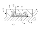
すなわち、図7及び図8に示されるように、ブッシュ本体16の製造に際しては、公知の構造を有する射出成形用型50が用いられる。この射出成形用型50は、上型52と下型54とを有し、上型52と下型54との型閉め状態下において、それらの型合せ面間に、ブッシュ本体16の外形形状に対応した形状を有する成形キャビティ56が形成されるようになっている。
That is, as shown in FIGS. 7 and 8, when the
このような射出成形用型50を用いて、ブッシュ本体16を製造するには、先ず、上型52と下型54との型閉めにより、ブッシュ本体16の外形形状に対応した形状を有する成形キャビティ56を形成する一方、かかる成形キャビティ56内の中心部に、ライナー布42を中芯型58に外挿させた状態で配置する。また、それと共に、二つの仕切部材26,26を、ライナー布42を間に挟んで、その径方向両側に、屈曲部28a,28b同士が対向配置するように、入れ子型(図示せず)にセットする。その際、二つの仕切部材26,26は、各屈曲部28a,28bの外フランジ部32a,32a,32b,32bの露出部34a,34a,34b,34bが入れ子型にて保持されることにより、位置決めされる。次いで、図示しない射出成形機から射出された未加硫ゴム60を、下型54のスプルー62を通じて、成形キャビティ56内に、導入させて、充填する。その後、成形キャビティ56内の未加硫ゴム60を固化させる。
In order to manufacture the bush
これにより、各仕切部材26,26の外側に位置する成形キャビティ56部分からなる外側ゴム部成形キャビティ部分64内で、外側ゴム部40を加硫成形する。それと共に、各仕切部材26,26とライナー布42との間に位置する成形キャビティ56部分からなる内側ゴム部成形キャビティ部分66内で、内側ゴム部38を加硫成形する。また、それと同時に、外側ゴム部40の内周面と内側ゴム部38の外周面とに対して、二つの仕切部材26,26を加硫接着する一方、内側ゴム部38の内周面に対して、ライナー布42を固着する。ここでは、内側ゴム部38が、ライナー布42を固着可能ではあるものの、厚さ方向において実質的に弾性変形不能な厚さとされる。そうして、図3及び図4に示される如き構造を有するブッシュ本体16を、二つの仕切部材26,26と共に一体加硫成形する。そして、それと同時に、ブッシュ本体16にライナー布42を固着させるのである。
As a result, the
このようなブッシュ本体16の一体加硫成形工程では、未加硫ゴム60が、外側ゴム部成形キャビティ部分64から内側ゴム部成形キャビティ部分66内に流入する。このとき、図7及び図8に矢印で示されるように、未加硫ゴム60の一部が、各仕切部材26,26の屈曲部28a,28bの外側を回って、内側ゴム部成形キャビティ部分66内に流れ込む。それと同時に、別の一部の未加硫ゴム60が、二つの仕切部材26,26に設けられた各貫通孔36a,36b,36cを通じて、内側ゴム部成形キャビティ部分66内に流れ込む。また、更に別の一部の未加硫ゴム60が、各仕切部材26,26の軸方向端縁部の外側を回って、内側ゴム部成形キャビティ部分66内に流れ込む。
In such an integral vulcanization molding process of the
そのため、ブッシュ本体16の一体加硫成形工程においては、例えば、貫通孔36a,36b,36cを有しない仕切部材を用いたときに、未加硫ゴム60の全部が、仕切部材の周方向端縁部や軸方向端縁部を回り込んで、内側ゴム部成形キャビティ部分内に流れ込む場合に比して、内側ゴム部成形キャビティ部分66内での未加硫ゴム60の流動距離が有利に小さくされる。そして、それにより、内側ゴム部成形キャビティ部分66内を流動する未加硫ゴム60の流動圧に基づいてライナー布42に加えられる圧力が、有利に低下され得る。
Therefore, in the integral vulcanization molding process of the bush
しかも、各貫通孔36a,36b,36cは、仕切部材26の周方向と軸方向とにおいてそれぞれ等分する位置のみに形成されている。そのため、仕切部材26の各屈曲部28a,28bの外側を回って、内側ゴム部成形キャビティ部分66内に流れ込んだ未加硫ゴム60の、内側ゴム部成形キャビティ部分66内での周方向の流動距離と、仕切部材26の各貫通孔36a,36b,36cを通じて、内側ゴム部成形キャビティ部分66内に流れ込んだ未加硫ゴム60の、内側ゴム部成形キャビティ部分66内での周方向の流動距離とが、互いに同一とされる。また、仕切部材26の軸方向端縁部の外側を回って、内側ゴム部成形キャビティ部分66内に流れ込んだ未加硫ゴム60の、内側ゴム部成形キャビティ部分66内での軸方向の流動距離と、仕切部材26の各貫通孔36a,36b,36cを通じて、内側ゴム部成形キャビティ部分66内に流れ込んだ未加硫ゴム60の、内側ゴム部成形キャビティ部分66内での軸方向の流動距離とが、互いに同一とされる。これによって、内側ゴム部成形キャビティ部分66内を流動する未加硫ゴム60の流動圧に基づいてライナー布42に加えられる圧力が、ライナー布42の周方向と軸方向とにおいて、それぞれ均一化され得る。
In addition, the through
それ故、ブッシュ本体16の一体加硫成形工程では、内側ゴム部38が薄肉であるために、内側ゴム部成形キャビティ部分66が狭幅とされているにも拘わらず、内側ゴム部成形キャビティ部分66内への未加硫ゴム60の部分的な充填不足が生ずることが、有利に回避され得る。また、ライナー布42が、未加硫ゴム60の流動圧によって部分的に波打った状態、或いは皺が発生した状態で、内側ゴム部38に固着される事態や、未加硫ゴム60の一部がライナー布42の内周面に滲み出して、その滲み出したゴムにより、ライナー布42の内周面が部分的に被覆される事態が生ずることも、効果的に解消され得る。
Therefore, in the integral vulcanization molding process of the
このように、本実施形態のスタビライザブッシュ10にあっては、ブッシュ本体16の製造時に、各仕切部材26,26に設けられた貫通孔36a,36b,36cが、未加硫ゴム60の流通路として利用されることにより、ライナー布42が、波打ちや皺のない、良好な真円形状を有し、且つその内側にゴム膜等が部分的に形成されることもなしに、内側ゴム部38の内周面に固着されるようになっている。それ故、かかるスタビライザブッシュ10は、スタビライザバー12が内孔18内に挿通されて、ボデー14に取り付けられた状態下で、ライナー布42の波打ちや皺、或いはライナー布42の内周面に部分的に形成されるゴム膜等に起因して、ライナー布42の周方向において、スタビライザバー12に対する摺動性能にバラツキが生ずることが有利に皆無とされる。その結果、スタビライザバーの捩り方向でのスムーズな回転が、常時、安定的に確保され得る。
As described above, in the
その上、本実施形態では、ブッシュ本体16の内側ゴム部38が、その厚さ方向において実質的に弾性変形不能な厚さとされている。そのため、スタビライザブッシュ10のボデー14への取付状態下で、スタビライザバー12が上下方向に相対変位して、ブッシュ本体16に対して上下方向の荷重が入力されたときに、内側ゴム部38の厚さ方向の弾性変形により、ライナー布42に撓みや皺が生ずることが、有利に防止され得る。これによっても、ライナー布42の優れた摺動性能に基づくスタビライザバー12の捩り方向でのスムーズな回転が、常時、安定的に確保され得る。
In addition, in the present embodiment, the
従って、かくの如き本実施形態のスタビライザブッシュ10にあっては、内側ゴム部38の肉厚が周方向において均一とされて、ライナー布42の内側ゴム部38に対する固着力と良好な防振性能とが安定的に確保され得る。その上、ブッシュ本体16の内周面とスタビライザバー12の外周面との間での捩りフリクションが、より効果的に且つ安定的に低減され得る。そして、その結果として、スタビライザバー12の捩り方向への回転に起因した異音の発生が、より有効に防止され得ると共に、良好な乗り心地性能が、更に有利に確保され得るのである。
Therefore, in the
しかも、かかるスタビライザブッシュ10では、二つの仕切部材26,26が、ブッシュ本体16に埋設されて、内側ゴム部38が上下方向の入力荷重に対して実質的に弾性変形しないようになっている。このため、ブッシュ本体16全体としてのばねの荷重−撓み特性におけるヒステリシスが効果的に小さくされ得る。そして、それにより、スタビライザブッシュ10が装着される自動車の操縦安定性が、効果的に高められ得ることとなる。
Moreover, in the
また、本実施形態のスタビライザブッシュ10においては、ブッシュ本体16の軸方向一方側の端面に一体形成されたゴム凸部22が、ブッシュ本体16の軸方向の一方側の端面から突出した仕切部材26,26の軸方向一端部及び各屈曲部28a,28bの外フランジ部32a,32a,32b,32bと、スタビライザバー12に外嵌固定されたストッパ金具49との接触乃至は当接を阻止する緩衝ゴム部として機能し得るようになっている。それ故、それら仕切部材26,26の軸方向一端部及び外フランジ部32a,32a,32b,32bとスタビライザバー12に外嵌固定されたストッパ金具49との接触乃至は衝突による異音の発生等の問題が、効果的に解消され得る。
Moreover, in the
さらに、かかるスタビライザブッシュ10では、貫通孔36a,36b,36cが、仕切部材26の周方向の中央部のみにおいて、軸方向に等間隔を隔てた位置に並んで設けられている。このため、例えば、軸方向に等間隔を隔てた箇所に設けられた貫通孔36a,36b,36cを、仕切部材26の周方向に等間隔を隔てた複数箇所に更に設ける場合に比して、貫通孔36a,36b,36cの数が少ない分だけ、仕切部材26の強度が、安定的に且つ有利に確保され得る。
Further, in the
また、本実施形態においては、仕切部材26の径方向両側に延び出す屈曲部28a,28bの軸方向両側端部からなる外フランジ部32a,32a,32b,32bが、ブッシュ本体16の加硫成形時において、成形キャビティ56内の所定位置に仕切部材26を位置決め保持するために、入れ子型等による被保持部分として形成されている。このため、例えば、外フランジ部を有しない、分割筒金具からなる仕切部材が、ブッシュ本体16の加硫成形時に、軸方向両側端部において、入れ子型等にセットされる場合に比して、仕切部材26が、成形キャビティ56内で、所定の位置に、より容易に且つ安定的に位置決め保持され得ることとなる。
In the present embodiment, the
以上、本発明の具体的な構成について詳述してきたが、これはあくまでも例示に過ぎないのであって、本発明は、上記の記載によって、何等の制約をも受けるものではない。 The specific configuration of the present invention has been described in detail above. However, this is merely an example, and the present invention is not limited by the above description.
例えば、図9に示されるように、ブッシュ本体16の平坦面からなる上面に対して、平板金具からなる上側ブラケット68を加硫接着しても良い。この場合には、例えば、公知の構造により、上側ブラケット68を、ボデー14の所定の取付位置に仮止めした状態で、或いは上側ブラケット68のボルト孔70を、ボデー14の取付孔(図示せず)に位置決めした状態で、ブッシュ本体16の軸方向中間部を下側ブラケット72の包囲部46にて包囲しつつ、下側ブラケット72の取付部48をボデー14にボルト固定することが出来る。これによって、ブッシュ本体16、ひいてはスタビライザブッシュ10のボデー14に対する取付操作が容易となる。なお、かかる図9と後述する図10乃至図12については、前記第一の実施形態と同様な構造とされた部材及び部位について、図1及び図2と同一の符号を付すことにより、その詳細な説明を省略する。
For example, as shown in FIG. 9, an
また、ブッシュ本体を二つの分割体にて構成することも出来る。つまり、軸方向に延びる分割面を備えた、半割筒状の二つの分割ゴム弾性体が互いに組み付けられて形成される筒状ゴム弾性体にて、ブッシュ本体を構成しても良いのである。 Further, the bush body can be constituted by two divided bodies. That is, the bush main body may be constituted by a cylindrical rubber elastic body formed by assembling two half-cylindrical divided rubber elastic bodies having a split surface extending in the axial direction.
例えば、図10に示されるように、ブッシュ本体74を、前記第一の実施形態におけるブッシュ本体16の下側半分の部分からなる第一分割ゴム部76と、かかるブッシュ本体16の上側半分の部分からなる第二分割ゴム部78とにて構成する。換言すれば、ブッシュ本体74を、略半割円筒状のゴム弾性体からなる第一分割ゴム部76と、長手矩形のブロック体からなり、下面に半円状の溝部80が軸方向に延びるように設けられた第二分割ゴム部78とを有する分割構造をもって構成するのである。
For example, as shown in FIG. 10, the bush
このような分割構造のブッシュ本体74を備えたスタビライザブッシュ10にあっては、第一分割ゴム部76の軸方向中間部に、仕切部材26が埋設されて、加硫接着されている。また、その内周面には、半割円筒状のライナー布42が固着されている。一方、第二分割ゴム部78の軸方向中間部にも、仕切部材26が埋設されて、加硫接着されている。また、溝部80の内周面には、半割円筒状のライナー布42が固着されている。そして、第一分割ゴム部76の仕切部材26の内周側に位置するゴム部分が、第一分割内側ゴム部82とされている一方、仕切部材26の外周側に位置するゴム部分が、第一分割外側ゴム部84とされている。また、第二分割ゴム部78の仕切部材26の内周側に位置するゴム部分が、第二分割内側ゴム部86とされている一方、仕切部材26の外周側に位置するゴム部分が、第二分割外側ゴム部88とされている。そして、第一分割ゴム部76の軸方向中間部の外周面に対して、下側ブラケット72(第二の実施形態において用いられるものと同様な構造を有する)が、包囲部46にて、第一分割ゴム部76の軸方向中間部を包囲した状態で、加硫接着されている。一方、第二分割ゴム部78の上面には、上側ブラケット68(第二の実施形態において用いられるものと同様な構造を有する)が加硫接着されている。
In the
このようなスタビライザブッシュ10は、第一分割ゴム部76と第二分割ゴム部78とが、スタビライザバー12を間に挟み、且つスタビライザバー12の外周面が、各ライナー布42,42の内周面に摺接するように組み付けられた状態で、上側ブラケット68と下側ブラケット72とを介して、ボデー14に装着されることとなる。
In such a
かくの如き構造とされた本実施形態のスタビライザブッシュ10においても、第一及び第二分割内側ゴム部82,86にて構成される内側ゴム部38と、ブッシュ本体74内に埋設される仕切部材26,26とが、前記第一の実施形態と同様な構造とされている。従って、本実施形態にあっても、前記第一の実施形態において奏される作用・効果と同様な作用・効果が、極めて有効に享受され得るのである。
Also in the
本実施形態のスタビライザブッシュ10では、第一分割ゴム部76の第一分割外側ゴム部84が、金属製で剛性の下側ブラケット72の包囲部46にて包囲された状態で、かかる包囲部46が、第一分割外側ゴム部84に加硫接着されている。これによって、第一分割外側ゴム部84の剛性の向上が有利に実現されて、第一分割外側ゴム部84において優れたばね特性が効果的に発揮され得る。そして、その結果として、防振性能が、より効果的に高められ得るのである。
In the
仕切部材26に形成される貫通孔36a,36b,36cは、未加硫ゴム60が通過可能な大きさで、仕切部材26に対して、それを周方向と軸方向とにおいてそれぞれ複数に実質的に等分する位置のみに形成されるものであれば、その大きさや形状、仕切部材26に対する具体的な形成位置と形成個数等が、特に限定されるものではない。それ故、例えば、図11及び図12に示されるように、仕切部材26を周方向に実質的に三等分する位置であって、且つ軸方向において二つ以上(ここでは五つ)に実質的に等分する位置のみに、貫通孔36をそれぞれ形成しても良いのである。
The through
ブッシュ本体16の軸方向の端面に一体形成されるゴム凸部22は、本発明において必須のものではない。しかしながら、スタビライザバー12がブッシュ本体16に対して軸方向に変位可能とされる場合には、ブッシュ本体16の軸方向両側端面のうち、少なくともスタビライザバー12の軸方向の変位によって、ストッパ金具49と接触する側の端面に一体形成されていることが望ましい。また、ブッシュ本体16の軸方向端面へのゴム凸部22の形成位置は、例示されたものに、何等限定されるものではない。例えば、ブッシュ本体16の軸方向端面に対して、内孔18の開口部の周りに、断続的に形成したり、その周上の一箇所だけに設けたり、内孔18の開口部の周り以外の部位に設けたりしても良い。ゴム凸部22の形状も、円環板形状以外の各種の形状が、適宜に採用され得る。
The rubber
ライナー布42を、内側ゴム部38や第一分割内側ゴム部82、第二分割内側ゴム部86の各内周面に対して加硫接着しても良い。
The
摺動部材は、例示されたものに、特に限定されるものではない。例えば、二硫化モリブデンやフッ素樹脂等からなる公知の摺動剤等を、内側ゴム部38や第一分割内側ゴム部82、第二分割内側ゴム部86の各内周面に、従来手法により焼き付ける等して、表面潤滑性を有するコーティング層を積層形成し、このコーティング層にて、摺動部材を構成することも出来る。
A sliding member is not specifically limited to what was illustrated. For example, a known sliding agent made of molybdenum disulfide, fluorine resin, or the like is baked on the inner peripheral surfaces of the
加えて、前記実施形態では、本発明を、自動車用スタビライザブッシュに適用したものの具体例を示したが、本発明は、自動車用以外の車両用スタビライザブッシュの何れに対しても、有利に適用され得るものであることは、勿論である。 In addition, in the above-described embodiment, a specific example of applying the present invention to an automotive stabilizer bush has been shown, but the present invention is advantageously applied to any of the vehicle stabilizer bushes other than the automobile. Of course, what you get.
その他、一々列挙はしないが、本発明は、当業者の知識に基づいて種々なる変更、修正、改良等を加えた態様において実施され得るものであり、また、そのような実施態様が、本発明の趣旨を逸脱しない限り、何れも、本発明の範囲内に含まれるものであることは、言うまでもないところである。 In addition, although not enumerated one by one, the present invention can be carried out in a mode to which various changes, modifications, improvements, etc. are added based on the knowledge of those skilled in the art. It goes without saying that all are included in the scope of the present invention without departing from the spirit of the present invention.
10 スタビライザブッシュ 12 スタビライザバー
16,74 ブッシュ本体 18 内孔
22 ゴム凸部 26 仕切部材
28a,28b 屈曲部 32a,32b 外フランジ部
34a,34b 露出部 36a,36b,36c 貫通孔
38 内側ゴム部 40 外側ゴム部
42 ライナー布 44 ブラケット
DESCRIPTION OF
Claims (9)
前記ブッシュ本体の前記内側ゴム部の厚さが、前記外側ゴム部の厚さよりも薄く、且つ該内側ゴム部に入力される荷重によって弾性変形しない厚さとされている一方、前記二つの仕切部材が、該ブッシュ本体の前記内孔への該スタビライザバーの挿通状態下で上下方向に互いに対応位置するように、該ブッシュ本体に埋設されていると共に、該二つの仕切部材のそれぞれが、それらの軸方向の両端部において、該ブッシュ本体の軸方向両側の端面から軸方向外方に突出する突出部を有し、且つ該突出部が、該仕切部材の軸方向両端部における周方向両端側部位に対して、軸直角方向外方に延び出すように一体形成された外フランジ部を含んで構成されており、更に、該ブッシュ本体を形成する前記ゴム弾性体を射出成形する際の未加硫ゴムが通過可能な貫通孔が、該二つの仕切部材のそれぞれに対して、該仕切部材を周方向と軸方向とにおいてそれぞれ複数に等分する位置のみに形成されており、そして該ブッシュ本体の軸方向両側の端面のうちの少なくとも何れか一方に対して、軸方向外方に突出するゴム凸部が、該ブッシュ本体の軸方向両側端面からの前記突出部の突出高さよりも高い高さを有して一体形成されていると共に、前記外フランジ部が、該ゴム凸部から該ブッシュ本体の軸直角方向外方に突出して、該ブッシュ本体の軸方向両側端面から外部に露出する露出部を含んでいることを特徴とする車両用スタビライザブッシュ。 (A) It is made of a cylindrical rubber elastic body having an inner hole penetrating in the axial direction, and a stabilizer bar is inserted into the inner hole in a non-adhesive manner, while being attached to the vehicle body via a bracket attached to the outer peripheral surface. A bush main body to be attached; and (b) the bush main body is embedded in an intermediate portion perpendicular to the axial direction of the bush main body so as to be divided into an inner rubber portion and an outer rubber portion, and is vulcanized and bonded to the bush main body. Two half-cylindrical partition members having rigidity, and (c) a sliding member fixed to the inner peripheral surface of the inner hole so as to be in sliding contact with the stabilizer bar inserted into the inner hole of the bushing body. In a vehicle stabilizer bush configured to include a moving member,
While the thickness of the inner rubber part of the bush body is smaller than the thickness of the outer rubber part and is not thickly elastically deformed by a load input to the inner rubber part, the two partition members are The bushing body is embedded in the bushing body so as to correspond to each other in the vertical direction under the state where the stabilizer bar is inserted into the inner hole of the bushing body, and each of the two partition members has a shaft thereof. At both ends in the direction, the protrusions protrude outward in the axial direction from the end surfaces on both sides in the axial direction of the bush body, and the protrusions are located at both ends in the circumferential direction at both ends in the axial direction of the partition member. On the other hand, it is configured to include an outer flange portion integrally formed so as to extend outward in a direction perpendicular to the axis, and further, an unvulcanized rubber when the rubber elastic body forming the bush body is injection-molded But Over Possible through holes for each of the two partition members, each of the partition member in the circumferential direction and the axial direction are formed only at positions equally divided into a plurality, and the axial direction of the bushing body A rubber convex portion protruding outward in the axial direction with respect to at least one of the end surfaces on both sides has a height higher than the protruding height of the protruding portion from the both axial end surfaces of the bushing body. And the outer flange portion includes an exposed portion that protrudes outward in the direction perpendicular to the axis of the bushing body from the rubber protrusion and is exposed to the outside from both end surfaces in the axial direction of the bushing body. A stabilizer bush for a vehicle characterized by comprising:
Priority Applications (1)
| Application Number | Priority Date | Filing Date | Title |
|---|---|---|---|
| JP2011534965A JP5386591B2 (en) | 2010-01-29 | 2011-01-28 | Stabilizer bush for vehicle |
Applications Claiming Priority (4)
| Application Number | Priority Date | Filing Date | Title |
|---|---|---|---|
| JP2010018362 | 2010-01-29 | ||
| JP2010018362 | 2010-01-29 | ||
| PCT/JP2011/051711 WO2011093430A1 (en) | 2010-01-29 | 2011-01-28 | Vehicle stabilizer bushing |
| JP2011534965A JP5386591B2 (en) | 2010-01-29 | 2011-01-28 | Stabilizer bush for vehicle |
Publications (2)
| Publication Number | Publication Date |
|---|---|
| JPWO2011093430A1 JPWO2011093430A1 (en) | 2013-06-06 |
| JP5386591B2 true JP5386591B2 (en) | 2014-01-15 |
Family
ID=44319411
Family Applications (1)
| Application Number | Title | Priority Date | Filing Date |
|---|---|---|---|
| JP2011534965A Active JP5386591B2 (en) | 2010-01-29 | 2011-01-28 | Stabilizer bush for vehicle |
Country Status (4)
| Country | Link |
|---|---|
| US (1) | US8292312B2 (en) |
| JP (1) | JP5386591B2 (en) |
| CN (1) | CN102470721B (en) |
| WO (1) | WO2011093430A1 (en) |
Families Citing this family (51)
| Publication number | Priority date | Publication date | Assignee | Title |
|---|---|---|---|---|
| JP4890371B2 (en) * | 2007-07-12 | 2012-03-07 | 本田技研工業株式会社 | Stabilizer support structure |
| JP5693012B2 (en) * | 2010-01-20 | 2015-04-01 | 倉敷化工株式会社 | Stabilizer bush |
| JP5622654B2 (en) | 2011-05-23 | 2014-11-12 | 住友理工株式会社 | Stabilizer bush for vehicle and manufacturing method thereof |
| JP6006290B2 (en) * | 2012-02-15 | 2016-10-12 | 本田技研工業株式会社 | bush |
| US8505940B1 (en) * | 2012-04-09 | 2013-08-13 | GM Global Technology Operations LLC | Stabilizer bar bushing attachment assembly |
| CN102941790A (en) * | 2012-10-23 | 2013-02-27 | 安徽誉丰汽车技术有限责任公司 | Stabilizer bar bushing structure of motor vehicle |
| JP5988488B2 (en) * | 2012-10-26 | 2016-09-07 | 日本発條株式会社 | Stabilizer bush, bonding jig, and bonding method |
| JP6054707B2 (en) * | 2012-11-02 | 2016-12-27 | 山下ゴム株式会社 | Vibration isolator |
| US20140260961A1 (en) * | 2013-03-13 | 2014-09-18 | GM Global Technology Operations LLC | Piston Pinbore Busing With Anti-Rotation Feature |
| US9074715B2 (en) * | 2013-03-15 | 2015-07-07 | Zsi, Inc. | Cushion insert for a tubing clamp and method of replacement |
| JP6284337B2 (en) * | 2013-10-21 | 2018-02-28 | 東洋ゴム工業株式会社 | Vibration isolator |
| JP6176196B2 (en) * | 2014-07-02 | 2017-08-09 | トヨタ自動車株式会社 | Stabilizer bar support device |
| DE102014116755A1 (en) * | 2014-11-17 | 2016-05-19 | Dr. Ing. H.C. F. Porsche Aktiengesellschaft | fastening device |
| JP6237597B2 (en) * | 2014-12-08 | 2017-11-29 | マツダ株式会社 | Open / close roof car |
| US20160280037A1 (en) | 2015-03-23 | 2016-09-29 | Toyota Motor Engineering & Manufacturing North America, Inc. | Stabilizer link |
| JP6347226B2 (en) | 2015-04-16 | 2018-06-27 | トヨタ自動車株式会社 | Stabilizer bar mounting device, stabilizer bar mounting bracket |
| JP6502177B2 (en) * | 2015-05-28 | 2019-04-17 | 株式会社ブリヂストン | Vibration control device |
| US9718325B2 (en) * | 2015-08-27 | 2017-08-01 | GM Global Technology Operations LLC | Lateral stabilization assembly |
| JP6330797B2 (en) * | 2015-11-30 | 2018-05-30 | トヨタ自動車株式会社 | Stabilizer bar holding device |
| JP6746304B2 (en) * | 2015-12-02 | 2020-08-26 | 日本発條株式会社 | Vehicle stabilizer device |
| JP6596350B2 (en) | 2016-02-15 | 2019-10-23 | 住友理工株式会社 | Stabilizer bush |
| JP6368728B2 (en) * | 2016-02-26 | 2018-08-01 | 住友理工株式会社 | Adhesive type stabilizer bush |
| JP2017177911A (en) * | 2016-03-29 | 2017-10-05 | 住友理工株式会社 | Producing method of stabilizer bar with rubber bush |
| CN106217751A (en) * | 2016-08-04 | 2016-12-14 | 安徽润康橡塑科技有限公司 | A kind of Automotive Stabilizer Bar and stabilizer bar bushing adhering technique |
| CN106218345A (en) * | 2016-08-09 | 2016-12-14 | 安徽纯启动力机械有限公司 | A kind of high-quality stabilizer bushing |
| CN106274344A (en) * | 2016-08-09 | 2017-01-04 | 安徽纯启动力机械有限公司 | The high intensity stabilizer bushing that a kind of band is protruding |
| CN106218346A (en) * | 2016-08-09 | 2016-12-14 | 安徽纯启动力机械有限公司 | A kind of automobile transverse stabilizer bar lining |
| CN106240277A (en) * | 2016-08-09 | 2016-12-21 | 安徽纯启动力机械有限公司 | A kind of Automotive Stabilizer Bar and stabilizer bar bushing assembly method |
| CN106183695A (en) * | 2016-08-09 | 2016-12-07 | 安徽纯启动力机械有限公司 | A kind of impact-resistant stabilizer bushing |
| CN106183696A (en) * | 2016-08-10 | 2016-12-07 | 安徽东升精密铸钢件有限公司 | A kind of impact-resistant stabilizer bushing of grinding tooth shape |
| CN106274348A (en) * | 2016-08-10 | 2017-01-04 | 安徽东升精密铸钢件有限公司 | A kind of anti-high-ductility stabilizer bushing jumped |
| CN106218347A (en) * | 2016-08-10 | 2016-12-14 | 安徽东升精密铸钢件有限公司 | A kind of high intensity stabilizer bushing of anti-axial jump |
| CN106274346A (en) * | 2016-08-10 | 2017-01-04 | 安徽东升精密铸钢件有限公司 | A kind of resistance to deformation stabilizer bushing of anti-axial jump |
| CN106274347A (en) * | 2016-08-10 | 2017-01-04 | 安徽东升精密铸钢件有限公司 | A kind of wear-resisting stabilizer bushing of anti-axial jump |
| CN106183698A (en) * | 2016-08-10 | 2016-12-07 | 安徽东升精密铸钢件有限公司 | A kind of stabilizer bushing preventing axial jump |
| CN106240278A (en) * | 2016-08-10 | 2016-12-21 | 安徽东升精密铸钢件有限公司 | A kind of wear-resisting stabilizer bushing of grinding tooth shape |
| CN106274349A (en) * | 2016-08-10 | 2017-01-04 | 安徽东升精密铸钢件有限公司 | A kind of grinding tooth shape stabilizer bushing of high intensity |
| CN106183697A (en) * | 2016-08-10 | 2016-12-07 | 安徽东升精密铸钢件有限公司 | A kind of grinding tooth shape stabilizer bushing |
| CN106274345A (en) * | 2016-08-10 | 2017-01-04 | 安徽东升精密铸钢件有限公司 | A kind of age inhibiting stabilizer bushing of grinding tooth shape |
| JP2018079752A (en) * | 2016-11-15 | 2018-05-24 | 東洋ゴム工業株式会社 | Stabilizer bush |
| JP6824704B2 (en) * | 2016-11-16 | 2021-02-03 | Toyo Tire株式会社 | Stabilizer bush |
| DE102016225179A1 (en) * | 2016-12-15 | 2018-07-05 | Zf Friedrichshafen Ag | Adjustable roll stabilizer for a chassis of a motor vehicle |
| US10155424B1 (en) * | 2017-06-22 | 2018-12-18 | Federal-Mogul Motorparts Corporation | Control arm with an improved bushing and method of making |
| US11209065B2 (en) | 2017-08-09 | 2021-12-28 | Vibracoustic Usa, Inc. | Low torsion bushing and assembly |
| CN107776356A (en) * | 2017-09-15 | 2018-03-09 | 北汽福田汽车股份有限公司 | Stabiliser bar fixation kit and there is its vehicle |
| JP7095572B2 (en) * | 2018-11-28 | 2022-07-05 | トヨタ自動車株式会社 | Stabilizer device and manufacturing method of stabilizer device |
| JP7200024B2 (en) | 2019-03-28 | 2023-01-06 | 住友理工株式会社 | stabilizer bush |
| DE102020211002B4 (en) | 2020-09-01 | 2022-06-02 | Zf Friedrichshafen Ag | bearing arrangement |
| US11658525B2 (en) * | 2020-10-09 | 2023-05-23 | GM Global Technology Operations LLC | Electric motor assembly using polymer-only fastening and methods of manufacturing the same |
| JP2022092517A (en) * | 2020-12-10 | 2022-06-22 | Toyo Tire株式会社 | Vibration control bush |
| CN113653728B (en) * | 2021-08-09 | 2022-08-26 | 株洲时代瑞唯减振装备有限公司 | Integrated support spherical hinge and assembling method thereof |
Citations (8)
| Publication number | Priority date | Publication date | Assignee | Title |
|---|---|---|---|---|
| GB1516572A (en) * | 1976-03-05 | 1978-07-05 | Joern Gmbh | Bushing assembly |
| JPH04316729A (en) * | 1991-04-15 | 1992-11-09 | Toyoda Gosei Co Ltd | Cylindrical vibration isolating bush |
| JPH0972365A (en) * | 1995-08-31 | 1997-03-18 | Tokai Rubber Ind Ltd | Vibration-proof rubber bush and manufacture thereof |
| JP2002321516A (en) * | 2001-04-27 | 2002-11-05 | Hokushin Ind Inc | Stabilizer bushing and molding method for the same |
| JP2004510930A (en) * | 2000-10-05 | 2004-04-08 | ツェットエフ レムフェルダー メタルヴァーレン アクチエンゲゼルシャフト | Rubber bearing with reinforcement element |
| JP2004142586A (en) * | 2002-10-24 | 2004-05-20 | Tokai Rubber Ind Ltd | Stabilizer bush |
| JP2007261538A (en) * | 2006-03-29 | 2007-10-11 | Tokai Rubber Ind Ltd | Stabilizer bush |
| JP2008213751A (en) * | 2007-03-07 | 2008-09-18 | Tokai Rubber Ind Ltd | Stabilizer bar with vibration-proof bushing, and its manufacturing method |
Family Cites Families (17)
| Publication number | Priority date | Publication date | Assignee | Title |
|---|---|---|---|---|
| US3007754A (en) * | 1958-12-24 | 1961-11-07 | George W Cross | Shaft bearing |
| US4007924A (en) * | 1975-06-27 | 1977-02-15 | Raoul Jorn | Elastic support mount |
| JPS6122944U (en) * | 1984-07-16 | 1986-02-10 | トヨタ自動車株式会社 | bushing assembly |
| US4744677A (en) * | 1984-11-27 | 1988-05-17 | Tokai Rubber Industries, Ltd. | Bush assemblage |
| JPS61134411A (en) | 1984-12-04 | 1986-06-21 | Hitachi Kiden Kogyo Ltd | Automatic dust remover |
| JPS61134411U (en) * | 1985-02-12 | 1986-08-21 | ||
| JPH0640484Y2 (en) * | 1988-09-20 | 1994-10-26 | トヨタ自動車株式会社 | Stabilizer bar bush |
| JPH0698994B2 (en) | 1992-07-16 | 1994-12-07 | 株式会社アメリカン・スーパー・ラベル | Video tape storage case and tape storage status display method |
| US5815411A (en) * | 1993-09-10 | 1998-09-29 | Criticom Corporation | Electro-optic vision system which exploits position and attitude |
| DE4309425C1 (en) * | 1993-03-24 | 1994-06-01 | Lemfoerder Metallwaren Ag | Rubber-metal support for vehicle leaf-spring suspension - has two half shells joined by flexible end bars |
| DE19709669C1 (en) * | 1997-03-11 | 1998-06-18 | Mannesmann Boge Gmbh | Rubber bearing for motor vehicle stabiliser bar |
| JP2000046110A (en) | 1998-07-28 | 2000-02-18 | Tokai Rubber Ind Ltd | Stabilizer bush |
| JP4560376B2 (en) * | 2004-10-29 | 2010-10-13 | 東海ゴム工業株式会社 | Stabilizer bush |
| JP2006170257A (en) | 2004-12-13 | 2006-06-29 | Toyo Tire & Rubber Co Ltd | Vibration control device and its mounting method |
| JP4238892B2 (en) * | 2006-03-30 | 2009-03-18 | 東海ゴム工業株式会社 | Fluid filled cylindrical vibration isolator |
| JP2008201307A (en) | 2007-02-21 | 2008-09-04 | Fuji Heavy Ind Ltd | Stabilizer device |
| JP5072762B2 (en) * | 2008-03-26 | 2012-11-14 | 東海ゴム工業株式会社 | Stabilizer bush |
-
2011
- 2011-01-28 JP JP2011534965A patent/JP5386591B2/en active Active
- 2011-01-28 CN CN201180002406.8A patent/CN102470721B/en active Active
- 2011-01-28 WO PCT/JP2011/051711 patent/WO2011093430A1/en active Application Filing
- 2011-08-09 US US13/205,840 patent/US8292312B2/en active Active
Patent Citations (8)
| Publication number | Priority date | Publication date | Assignee | Title |
|---|---|---|---|---|
| GB1516572A (en) * | 1976-03-05 | 1978-07-05 | Joern Gmbh | Bushing assembly |
| JPH04316729A (en) * | 1991-04-15 | 1992-11-09 | Toyoda Gosei Co Ltd | Cylindrical vibration isolating bush |
| JPH0972365A (en) * | 1995-08-31 | 1997-03-18 | Tokai Rubber Ind Ltd | Vibration-proof rubber bush and manufacture thereof |
| JP2004510930A (en) * | 2000-10-05 | 2004-04-08 | ツェットエフ レムフェルダー メタルヴァーレン アクチエンゲゼルシャフト | Rubber bearing with reinforcement element |
| JP2002321516A (en) * | 2001-04-27 | 2002-11-05 | Hokushin Ind Inc | Stabilizer bushing and molding method for the same |
| JP2004142586A (en) * | 2002-10-24 | 2004-05-20 | Tokai Rubber Ind Ltd | Stabilizer bush |
| JP2007261538A (en) * | 2006-03-29 | 2007-10-11 | Tokai Rubber Ind Ltd | Stabilizer bush |
| JP2008213751A (en) * | 2007-03-07 | 2008-09-18 | Tokai Rubber Ind Ltd | Stabilizer bar with vibration-proof bushing, and its manufacturing method |
Also Published As
| Publication number | Publication date |
|---|---|
| JPWO2011093430A1 (en) | 2013-06-06 |
| US20110291377A1 (en) | 2011-12-01 |
| CN102470721B (en) | 2014-06-18 |
| US8292312B2 (en) | 2012-10-23 |
| WO2011093430A1 (en) | 2011-08-04 |
| CN102470721A (en) | 2012-05-23 |
Similar Documents
| Publication | Publication Date | Title |
|---|---|---|
| JP5386591B2 (en) | Stabilizer bush for vehicle | |
| JP5622654B2 (en) | Stabilizer bush for vehicle and manufacturing method thereof | |
| JP5456898B2 (en) | Elastic bushings, especially compound steering bushings | |
| US9291228B2 (en) | Vibration absorber | |
| JP2008223920A (en) | Vibration control bush and vibration control bush assembly | |
| US20120074630A1 (en) | Anti-vibration bush | |
| JP6343535B2 (en) | Cylindrical vibration isolator | |
| JP2012097878A (en) | Vibration control connecting rod | |
| JP4081114B2 (en) | Anti-vibration device manufacturing method | |
| KR101592347B1 (en) | Mount bush of stabilizer bar for vehicle | |
| JP3951274B1 (en) | Anti-vibration bushing manufacturing method | |
| JP5595203B2 (en) | Toe collect bush | |
| JP2010060022A (en) | Vibration damping bushing | |
| JP5302868B2 (en) | Stabilizer bar with anti-vibration bush and manufacturing method thereof | |
| JP6257353B2 (en) | Stabilizer bush | |
| KR20160076029A (en) | Bush and Method for manufacturing the bush | |
| JP2010137688A (en) | Method of manufacturing stabilizer bar with vibration control bush | |
| KR20110132744A (en) | Mount bush of stabilizer bar for vehicle | |
| JP4937062B2 (en) | Stabilizer bar with stabilizer bush | |
| JP4937063B2 (en) | Stabilizer bar with stabilizer bush | |
| JP3932025B2 (en) | Anti-vibration bush | |
| JP6126889B2 (en) | Liquid seal type vibration isolator | |
| JP2009073366A (en) | Stabilizer bar with stabilizer bush, and its manufacturing method | |
| JP2008163986A (en) | Vibration control bush | |
| JPS63270913A (en) | Connecting rod with rubber bush |
Legal Events
| Date | Code | Title | Description |
|---|---|---|---|
| A131 | Notification of reasons for refusal |
Free format text: JAPANESE INTERMEDIATE CODE: A131 Effective date: 20130514 |
|
| A521 | Request for written amendment filed |
Free format text: JAPANESE INTERMEDIATE CODE: A523 Effective date: 20130626 |
|
| TRDD | Decision of grant or rejection written | ||
| A01 | Written decision to grant a patent or to grant a registration (utility model) |
Free format text: JAPANESE INTERMEDIATE CODE: A01 Effective date: 20131001 |
|
| A61 | First payment of annual fees (during grant procedure) |
Free format text: JAPANESE INTERMEDIATE CODE: A61 Effective date: 20131007 |
|
| R150 | Certificate of patent or registration of utility model |
Ref document number: 5386591 Country of ref document: JP Free format text: JAPANESE INTERMEDIATE CODE: R150 Free format text: JAPANESE INTERMEDIATE CODE: R150 |
|
| S533 | Written request for registration of change of name |
Free format text: JAPANESE INTERMEDIATE CODE: R313533 |
|
| R350 | Written notification of registration of transfer |
Free format text: JAPANESE INTERMEDIATE CODE: R350 |