JP5373097B2 - Electric toothbrush and brush head for electric toothbrush - Google Patents
Electric toothbrush and brush head for electric toothbrush Download PDFInfo
- Publication number
- JP5373097B2 JP5373097B2 JP2011533924A JP2011533924A JP5373097B2 JP 5373097 B2 JP5373097 B2 JP 5373097B2 JP 2011533924 A JP2011533924 A JP 2011533924A JP 2011533924 A JP2011533924 A JP 2011533924A JP 5373097 B2 JP5373097 B2 JP 5373097B2
- Authority
- JP
- Japan
- Prior art keywords
- tufts
- brush head
- hair
- cross
- section
- Prior art date
- Legal status (The legal status is an assumption and is not a legal conclusion. Google has not performed a legal analysis and makes no representation as to the accuracy of the status listed.)
- Active
Links
Images


Classifications
-
- A—HUMAN NECESSITIES
- A61—MEDICAL OR VETERINARY SCIENCE; HYGIENE
- A61C—DENTISTRY; APPARATUS OR METHODS FOR ORAL OR DENTAL HYGIENE
- A61C17/00—Devices for cleaning, polishing, rinsing or drying teeth, teeth cavities or prostheses; Saliva removers; Dental appliances for receiving spittle
- A61C17/16—Power-driven cleaning or polishing devices
- A61C17/22—Power-driven cleaning or polishing devices with brushes, cushions, cups, or the like
- A61C17/222—Brush body details, e.g. the shape thereof or connection to handle
-
- A—HUMAN NECESSITIES
- A46—BRUSHWARE
- A46B—BRUSHES
- A46B13/00—Brushes with driven brush bodies or carriers
- A46B13/02—Brushes with driven brush bodies or carriers power-driven carriers
-
- A—HUMAN NECESSITIES
- A46—BRUSHWARE
- A46B—BRUSHES
- A46B9/00—Arrangements of the bristles in the brush body
- A46B9/02—Position or arrangement of bristles in relation to surface of the brush body, e.g. inclined, in rows, in groups
- A46B9/028—Bristle profile, the end of the bristle defining a surface other than a single plane or deviating from a simple geometric form, e.g. cylinder, sphere or cone
-
- A—HUMAN NECESSITIES
- A46—BRUSHWARE
- A46B—BRUSHES
- A46B9/00—Arrangements of the bristles in the brush body
- A46B9/02—Position or arrangement of bristles in relation to surface of the brush body, e.g. inclined, in rows, in groups
- A46B9/04—Arranged like in or for toothbrushes
Abstract
Description
本発明は、電気歯ブラシ、及び電気歯ブラシ用の駆動可能なブラシヘッドに関し、この電気歯ブラシは、毛支持体を可動式に装着するための装着手段を含む毛支持体と、毛支持体上に配列された複数の毛房と、を有する。 The present invention relates to an electric toothbrush and a drivable brush head for an electric toothbrush, the electric toothbrush comprising an attachment means for movably attaching the bristle support and an array on the bristle support A plurality of tresses.
駆動可能な毛セクションを伴うと、毛支持体上に高い毛密度を達成することが困難であることがしばしばあり、特に、アンカータフティングと呼ばれる手法を用いて毛支持体に毛房を固定することが望まれるときは、なおさらである。一方、電気歯ブラシの駆動可能な毛支持体は、駆動運動を歯の表面に集中させるための表面積が比較的小さく、特に、その駆動が振動回転運動を実行するときはなおさらである。一方、駆動可能な毛セクションには、特別な房の構成が望まれる。例えば、回転運動で振動する丸形の毛支持体では、隣接歯の間にそれらが貫通することを可能にするために、しばしば、歯ブラシの長手方向軸の区域にパワーチップ(すなわち、他の房より高く、他の房を超えて突出する歯ブラシの房)が備えられる。毛支持体の外周辺上のそのような毛房は、便利なことに、幅が狭く長手方向に延びる房の断面を有する細長い輪郭を有するので、隣接歯間の洗浄効果を向上することを可能にし、加えて、毛セクションに適用された歯磨剤を作業表面上によりよく保持することを可能にする。 With a drivable hair section, it is often difficult to achieve high hair density on the hair support, especially using a technique called anchor tufting to fix the tufts on the hair support Especially when it is desired. On the other hand, the driveable bristle support of an electric toothbrush has a relatively small surface area for concentrating the drive motion on the tooth surface, especially when the drive performs an oscillating rotational motion. On the other hand, a special tuft configuration is desired for the drivable hair section. For example, round bristle supports that vibrate in rotational motion often have power tips (ie other tufts) in the area of the longitudinal axis of the toothbrush to allow them to penetrate between adjacent teeth. Toothbrush tufts) that are higher and project beyond other tufts. Such tresses on the outer periphery of the bristle carrier conveniently have an elongated profile with a narrow, longitudinally extending tress cross section, which can improve the cleaning effect between adjacent teeth In addition, it allows the dentifrice applied to the hair section to be better retained on the work surface.
例えば、EP 0835081 B1号に開示されている房は、長手方向軸の領域において円形の回転運動可能な毛セクションの周囲に配置されており、それらよりも内側に配置された房を超えて突出している。毛セクションの外周辺上のそのような延びた房は、隣接歯間の洗浄効果を高めることを実際可能にするが、隣接歯の間に隣接する歯側面(tooth flank)の部分に対する洗浄作用は、いまだに最適化されていない。一方、そのような構成の毛セクションを1つの歯から別の歯へと、ごくやさしく移動することができないために、歯ブラシの長手方向へのブラシヘッドのブラッシング運動によって突き刺されるような感覚がもたらされる。 For example, the tufts disclosed in EP 083581 B1 are arranged around a circular rotationally movable hair section in the region of the longitudinal axis and project beyond the tufts arranged inside them. Yes. Such extended tufts on the outer periphery of the bristle section actually make it possible to enhance the cleaning effect between adjacent teeth, but the cleaning action on the adjacent tooth flank portion between adjacent teeth is not It has not been optimized yet. On the other hand, since the bristle section of such a configuration cannot be moved very gently from one tooth to another, the sensation of being pierced by the brushing movement of the brush head in the longitudinal direction of the toothbrush is brought about. .
回転運動可能な同様の造りの、毛セクションの作業表面内に中央凹部又はくぼみを含むブラシヘッドは、US−D 478,214号、US−D 517,325号、又はUS−D 455,556号により既知である。 A brush head of similar construction, capable of rotational movement, including a central recess or indentation in the working surface of the bristle section is US-D 478,214, US-D 517,325, or US-D 455,556. Is known.
その毛セクションの外周辺上の細長い毛房は、いくつかのアンカーワイヤとともに固着されなくてはならず、それに対応する間隔を要求するので、そのような細長い毛房は、アンカータフティング法という手段によって房を固着するときに毛支持体上に高い毛密度を達成することを可能にするための、前述の問題を悪化させる。 Since the elongated tufts on the outer periphery of the hair section must be secured with several anchor wires and require a corresponding spacing, such elongated tufts are a means of anchor tufting Exacerbates the above-mentioned problems, which make it possible to achieve a high hair density on the hair support when anchoring the tuft.
前述のことを鑑みて、本発明は、先行技術の不利な点を抑える一方で、当該技術をより有利に更に開発する、改善された電気歯ブラシ及び改善されたブラシヘッドを設けることを望む。具体的には、アンカータフティング法によって毛房を固定する可能性をなくすことなく、毛支持体上に高い毛密度を達成することが望ましい。 In view of the foregoing, the present invention desires to provide an improved electric toothbrush and an improved brush head that reduce the disadvantages of the prior art while further advantageously developing the technology. Specifically, it is desirable to achieve a high hair density on the hair support without eliminating the possibility of anchoring the tufts by anchor tufting.
この目的は、本発明にしたがって、請求項1、請求項17又は請求項18に記載のブラシヘッドと、請求項20に記載の電気歯ブラシとによって達成される。本発明の好ましい実施形態については、従属クレームに記述する。
This object is achieved according to the invention by a brush head according to
本発明の一態様にしたがい、毛支持体の可動式装着のための装着手段を有する毛支持体を備えるブラシヘッドが提案される。毛支持体は、好ましくはほぼ皿形状である。一実施形態では、毛支持体の回転振動の動きが可能となるように装着手段が配列される。複数の毛房は、毛支持体上に配列される。本発明の一態様では、毛支持体は、2つの中央毛房を含む毛セクションを備える中央区域を有し、これらの毛房の断面は、中央区域に隣接して配列された中間毛房の断面より大きい。中央毛房は、細長い形状を有し、具体的には、それらはほぼ半月のような形又はバナナのような形又は腎臓のような形を有するが、直線形の細長い房の中央毛房を除外するべきではない。2つの中央房は、それらの断面形状が互いを補完するように配列され、それによって、特にその毛セクションは、ほぼ円形、卵形、又は楕円構造を有することになる(この構造は、それら2つの中央毛房を備える凸面の包囲された区域によって画定され得る)。概して、2つの中央毛房によって形成される毛セクションの横寸法は、第1の横幅の測定値が、この第1の横幅に対して垂直の第2の横幅の約50%〜100%の寸法であり、具体的には、第1の横幅は第2の横幅の約70%〜約90%である。ここで注意すべきことは、用語「毛房」を、必ずしも長繊維の単一の房が単一の工程によって(例えばアンカータフティングによって)毛支持体に固定されたものとして理解すべきではなく、いくつかの小さい毛房を合わせてより大きいサイズの毛房(「複合毛房」)が形成される多工程プロセスによって構成されたものである場合があるにも関わらず、本質的に単一の毛房のように見える毛房に関係するものとして理解すべきである。更に注意すべきことは、毛房の(房の)断面が、毛支持体の毛房を乗せた表面に対して平行な平面において画定され、複合毛房が単一の毛房のように見えると仮定されることである。 In accordance with one aspect of the present invention, a brush head is proposed that includes a bristle support having attachment means for movable attachment of the bristle support. The bristle carrier is preferably substantially dish-shaped. In one embodiment, the mounting means are arranged to allow rotational vibration movement of the bristle support. The plurality of hair tresses are arranged on the hair support. In one aspect of the invention, the bristle carrier has a central section comprising a hair section comprising two central tufts, the cross-section of these tufts of intermediate tufts arranged adjacent to the central section. Larger than cross section. The central tress has an elongated shape, in particular, they have a roughly half-moon-like shape or a banana-like shape or a kidney-like shape, but the straight-shaped elongated tress is a central tress. Should not be excluded. The two central tresses are arranged so that their cross-sectional shapes complement each other, so that in particular their hair section will have a substantially circular, oval or elliptical structure (this structure is Can be defined by a convex enclosed area with two central tresses). Generally, the lateral dimension of the hair section formed by the two central tufts is such that the first lateral measurement is about 50% to 100% of the second lateral width perpendicular to the first lateral width. Specifically, the first width is about 70% to about 90% of the second width. It should be noted here that the term “hair” is not necessarily to be understood as a single strand of long fibers fixed to the hair support by a single step (eg by anchor tufting). In spite of being composed of a multi-step process where several smaller tufts are combined to form larger sized tufts (“composite tufts”), It should be understood as related to the tufts that look like the tufts of hair. It should be further noted that the cross-section of the tuft is defined in a plane parallel to the surface of the hair support on which the tuft rests, so that the composite tuft looks like a single tuft. It is assumed that
本発明の更なる態様にしたがい、毛支持体上に配列される複数の毛房は、互いに入れ子になって内側に収まる輪又は領域において設けられる。したがって、外側の輪又は領域が存在し、その上に外側毛房が装着され、中間の輪又は領域が存在し、この中間の輪又は領域は、外側の輪の内側で入れ子になっており、この中間の輪又は領域上に中間毛房が装着される。本発明のこの態様において、外側毛房は、細長い房断面を有し、外側毛房は、外側の輪又は領域の対向する側に配列される。更に、中間毛房は、外側毛房の断面より小さい断面を有する。本発明のこの態様において、上述のような2つの中央毛房を含む中央区域は、中間の輪又は領域の中央に設けられ、中央領域と隣接する中間毛房は、外側毛房及び中央毛房より小さい断面を有する。 According to a further aspect of the invention, the plurality of tresses arranged on the hair support are provided in a ring or region that is nested inside and fits inside. Thus, there is an outer ring or region on which the outer hair tuft is mounted, there is an intermediate ring or region, this intermediate ring or region is nested inside the outer ring, An intermediate tress is mounted on this intermediate ring or region. In this aspect of the invention, the outer hair tuft has an elongated tuft cross section, and the outer hair tuft is arranged on the opposite side of the outer ring or region. Furthermore, the intermediate tress has a cross section that is smaller than the cross section of the outer tress. In this aspect of the invention, a central area comprising two central tresses as described above is provided in the middle of the middle ring or region, and the intermediate fibrils adjacent to the central region are the outer and central tresses. Has a smaller cross section.
大きいサイズの中央毛房を設けることは、動作中のブラシヘッドの中央区域の安定性の向上をもたらす。通常、使用者はブラシヘッドの中央区域を歯の表面に対して押し付けるので、毛密度(房の安定性)が低すぎると、中央区域の毛はその付加された力によって屈曲することになり、結果的に洗浄効果が低減される。共になってほぼ円形、卵形、又は楕円の断面構造を有する提案されている中央毛房は、互いに十分な安定性を設けるので、中央区域の毛の屈曲は効率的に回避される。中央毛房の周囲に、より小さいサイズの中間毛房を設けることによって、毛支持材上に毛房の高密度をもたらすことが可能になる。細長い外側毛房を更に設けることは、毛支持材上の高い毛密度を更に支えるだけでなく、全体の毛房の場の周辺境界上の毛の場全体のための安定性もまた設ける。このように、大きいサイズの中央毛房を設けることは、本発明の一態様にしたがって、高い毛密度及び高い中央安定性をもたらすことになる。提案されているような、入れ子の輪又は領域に設けられる中間毛房及び外側毛房の更なる供給は、本発明の更なる態様の範囲内で、高い毛密度及び周辺の安定性をもたらす。 Providing a large central tress provides improved stability of the central area of the brush head during operation. Usually, the user presses the central area of the brush head against the tooth surface, so if the hair density (stability of the tuft) is too low, the hair in the central area will bend by its applied force, As a result, the cleaning effect is reduced. The proposed central tresses, which together have a generally circular, oval or elliptical cross-sectional structure, provide sufficient stability to each other so that bending of the hair in the central area is effectively avoided. By providing a smaller sized intermediate tress around the central tress, it is possible to provide a higher density of tresses on the hair support. Further provision of elongated outer tresses not only further supports the high hair density on the hair support, but also provides stability for the entire hair field on the peripheral boundary of the entire hair field. Thus, providing a large sized central hair tuft will provide high hair density and high central stability in accordance with one aspect of the present invention. The further supply of intermediate and outer tresses provided in the nesting rings or regions, as proposed, provides high hair density and peripheral stability within the scope of further aspects of the invention.
一実施形態では、2つの中央房を備える包囲された円形区域内の毛区域は、包囲された円形区域の少なくとも約40%〜約80%の割合である。特定すると、有毛区域は、前記包囲された円形区域の少なくとも約50%である一部(fraction)を覆い、特定すると、有毛区域は、少なくとも約60%である。 In one embodiment, the hair area within the enclosed circular area comprising two central tufts is a proportion of at least about 40% to about 80% of the enclosed circular area. In particular, the hair area covers a fraction that is at least about 50% of the enclosed circular area, and in particular, the hair area is at least about 60%.
別の実施形態では、包囲された円形区域は、毛支持体の全面積の約5%〜約15%である。特定の実施形態では、包囲された円形区域は、毛支持体の面積の約7%〜約9%である。 In another embodiment, the enclosed circular area is about 5% to about 15% of the total area of the hair support. In certain embodiments, the enclosed circular area is about 7% to about 9% of the bristle carrier area.
更なる実施形態では、中間毛房は、ほぼ同等のサイズの断面積を有する。これは、同じタフティング機を用いて全ての中間毛房を装着する、比較的シンプルな製造が可能になる。また更なる実施形態では、複数の毛房(外側毛房、中間毛房及び中央毛房を含む)のそれぞれの毛房は、基底面積とほぼ同一の断面積又は基底面積の整数倍数である断面積を有する。この場合、同じタフティング機を使用して全ての毛房を装着することができ、より大きいサイズの毛房は、細長い装着穴に並んで装着される2つ以上の基底毛房から組み立てられ、それによって、複合毛房を形成する。 In a further embodiment, the intermediate tress has a cross-sectional area of approximately the same size. This allows for a relatively simple production where all intermediate tresses are mounted using the same tufting machine. In still further embodiments, each of the plurality of tresses (including outer tress, intermediate tress and central tress) has a cross-sectional area that is substantially the same as the basal area or an integer multiple of the basal area. Has an area. In this case, all the tufts can be mounted using the same tufting machine, the larger tufts being assembled from two or more basal tufts mounted side by side in the elongated mounting holes, Thereby, a complex hair tuft is formed.
言い換えれば、より高い毛(又は毛房)充填密度が中央区域に設けられ、中央の歯係合区域を形成し、その毛密度の結果として、毛の長さに沿った更なる沈下を防ぐ。この、中央の毛セクションの毛の末端でのより高い密度は、複数の直接隣接する毛房(約1.5mm未満又は特定すると約1mm未満の距離を有する)によって得られる。中央区域に装着される毛房は、2つのより大きいサイズの複合毛房(ただし、それらを固定するために1つ以上のアンカータフティングワイヤを必要とする)を形成するように組み合わされる、及び/又は、皿形状の毛支持体から前進する中央毛房が互いに対して傾き、実質的にタフティング間隙が一切ない密な毛セクションを毛の末端が形成するようにしてもよい。したがって、中央の毛セクションの高密度の毛の末端は、上記の手段のいずれか1つによって、又は上記の3つのアプローチを所望により任意に組み合わせることによって、達成可能である。 In other words, a higher hair (or tuft) filling density is provided in the central area, forming a central tooth-engaging area, which prevents further settlement along the length of the hair as a result of that hair density. This higher density at the hair ends of the central hair section is obtained by a plurality of directly adjacent tresses (having a distance of less than about 1.5 mm, or in particular less than about 1 mm). The tufts attached to the central area are combined to form two larger sized composite tufts (but require one or more anchor tufting wires to secure them), and Alternatively, the central tresses that advance from the dish-shaped hair support may be inclined relative to each other so that the hair ends form a dense hair section with substantially no tufting gap. Thus, the dense hair ends of the central hair section can be achieved by any one of the above means or by any combination of the above three approaches as desired.
したがって、毛支持体の周辺外縁(外側毛房)及びその中央区域(中央毛房)に大きい断面積の毛房を集中させること、更に、縁及び中央にある、これらの大きい面積の毛房の間に、小さい断面積の房を中間の房の輪(中間毛房)の上に設けること、並びにその断面の幾何学及びそれらの相対的配向を賢く選択することによって、毛が密に充填されている場合でさえも房締結手段の衝突を回避することが、提案される。本発明によると、外側の輪上の細長い外側毛房の内側に、中間の輪上に配列された、細長い毛房の断面より小さい断面のいくつかの中間毛房があり、中間の輪上のこれらのより小さい房の内側に、中間の輪上の房の断面より大きい断面を有する少なくとも2つの房が設けられる。内側から外側への房断面のこの周期交代のおかげで、高い房密度が達成可能であり、締結手段の衝突がいっそう回避可能になる。加えて、洗浄効果に関する有利な結果ももたらされる。毛は、毛房ではない組み合わせによっても設けられ得ると理解されたい。したがって、上記の説明及び下記請求項に述べるように、毛房の参照は全て、本発明による毛の多数の参照として、代替的にみなされ得る。更に、毛の代わりに他のタイプの歯洗浄要素を代替的に使用してもよい。更に、この文脈において記述された毛房は、外側、中間、及び内側の輪の代わりに、相対的に配列された外側、中間、又は内側の領域上に配列されてもよい。 Thus, concentrating the large cross-sectional tresses on the peripheral outer edge (outer tress) and its central area (central tress) of the hair support, and also on the rim and center of these larger area tresses In between, the hairs are tightly packed by providing a small cross-section tuft on the middle tuft ring (intermediate tuft) and intelligently choosing the cross-sectional geometry and their relative orientation. It is proposed to avoid collision of the tuft fastening means even when According to the present invention, inside the elongated outer tress on the outer ring, there are a number of intermediate tresses arranged on the middle ring and having a cross section smaller than that of the elongated tress, on the middle ring Inside these smaller tufts are provided at least two tufts having a cross section larger than the cross section of the tuft on the middle ring. Thanks to this periodic alternation of the tuft cross section from the inside to the outside, a high tuft density can be achieved and the collision of the fastening means can be further avoided. In addition, advantageous results regarding the cleaning effect are also provided. It should be understood that hair can also be provided by a combination that is not a tuft. Thus, as described in the above description and the claims below, all reference to the tufts can alternatively be considered as multiple references to hair according to the present invention. In addition, other types of tooth cleaning elements may alternatively be used instead of hair. In addition, the tufts described in this context may be arranged on relatively arranged outer, middle or inner regions instead of outer, middle and inner rings.
そのほか、毛セクションの中央に通常適用される歯磨剤は、作業表面に、よりよく保持される。 In addition, the dentifrice normally applied to the center of the hair section is better retained on the work surface.
本発明の更なる態様において、様々な断面形を有する中間毛房は、少なくとも1つの中間の毛の輪に配列される。具体的には、前記少なくとも1つの中間の輪の中間毛房は、ほぼ正方形の房断面を有するように設けられ得る。あるいは、又は加えて、前記中間の輪はまた、丸い断面、具体的には、円形断面を有する中間毛房も含むことができる。角形(特定すると正方形)である場合、及び丸(特定すると円形)である場合、毛房は、前記中間の輪に配列され、それぞれ異なるセクターに有利に集中される。これを行うための様々な選択肢が一般に存在する。本発明の一実施形態によると、丸い中間毛房は、対向するセクターにある中間の輪上に配列され、毛支持体が偏向されていない中立位にある場合、それらは歯ブラシの長手方向軸を含む。これに対し、中間の輪の角形の毛房は、毛支持体の対向するセクターに有利に配列され、毛支持体の中立位では、横軸に対称に配列される。 In a further aspect of the invention, intermediate tresses having various cross-sectional shapes are arranged in at least one intermediate hair ring. Specifically, the intermediate tufts of the at least one middle ring may be provided with a substantially square tuft cross section. Alternatively or in addition, the intermediate ring can also include intermediate tresses having a round cross-section, in particular a circular cross-section. In the case of a square (specifically square) and a circle (specifically circular), the tufts are arranged in the middle ring and are advantageously concentrated in different sectors. There are generally various options for doing this. According to one embodiment of the invention, the round intermediate tresses are arranged on an intermediate ring in the opposite sector and when the bristle carrier is in an undeflected neutral position, they are aligned with the longitudinal axis of the toothbrush. Including. On the other hand, the angular tresses of the middle ring are advantageously arranged in opposite sectors of the hair support and are arranged symmetrically on the horizontal axis in the neutral position of the hair support.
毛房の固定のために好ましい間隔条件を設けるために、本発明の更なる態様では、中間の輪の角形の毛房(少なくともそれらのいくつか)は、毛支持体の主軸に対して、及びそれらが配列されている輪の環状輪郭に対しても、鋭角に回転される。具体的には、角形毛房の少なくとも1つ、好ましくは1つ置きの角形毛房の主軸は、毛房断面の主軸が中間の輪の接線に対して鋭角に傾斜されるように回転される。結果的に、対応するアンカープレートは、他のアンカープレートの衝突範囲外に回転される。加えて、毛セクション全体の撓み挙動を全体的により均一にすること、特に、方向への依存を少なくすることができる。 In order to provide favorable spacing conditions for the fixation of the tufts, in a further aspect of the invention, the mid-ring angular tufts (at least some of them) are relative to the main axis of the bristle carrier and It is also rotated at an acute angle relative to the annular contour of the ring in which they are arranged. In particular, the main axis of at least one, preferably every other, square hair of the tuft is rotated so that the main axis of the tuft cross section is inclined at an acute angle with respect to the tangent to the middle ring. . As a result, the corresponding anchor plate is rotated out of the collision range of the other anchor plate. In addition, the overall bending behavior of the whole hair section can be made more uniform, in particular less dependent on the direction.
断面形が異なっていても、中間の輪の毛房は、少なくともほぼ同じ面積の断面を有し、それらの断面積の変化は好ましくは約+/−25%未満、特定すると約+/−10%未満、更に特定すると約+/−3%未満の範囲内である。 Even though the cross-sectional shapes are different, the middle ring tufts have a cross-section of at least approximately the same area, and their change in cross-sectional area is preferably less than about +/− 25%, specifically about +/− 10. %, And more particularly within the range of less than about +/− 3%.
中間の輪の毛房の断面積と比較して、外側の輪上の細長い外側毛房及び中央区域の少なくとも2つの最も内側の中央毛房は、少なくとも2倍大きい断面積を有する。 Compared to the cross-sectional area of the middle ring tress, the elongated outer tress on the outer ring and the at least two innermost central tresses in the central section have a cross-sectional area that is at least twice as large.
この構造では、毛セクションの外側の輪に、いくつかの対向して置かれた対の細長い外側毛房が配置されている場合がある。毛セクションの異なる区域における異なる洗浄作用に毛の構成をより良く適応させるために、前記外側の輪は、毛の長さ及び/又は高さ及び/又は断面積において異なる、異なる設計の対の細長い毛房を含むことができる。 In this configuration, several opposed pairs of elongated outer tresses may be disposed on the outer ring of the hair section. In order to better adapt the hair configuration to different cleaning actions in different areas of the hair section, the outer ring is elongated in pairs of different designs that differ in hair length and / or height and / or cross-sectional area. Hair tufts can be included.
概して、この文脈において様々な構成が可能である。本発明の実施形態によると、毛支持体の対向するセクターは、毛支持体が偏向されていないその中立位では、歯ブラシの長手方向軸を包含し、歯ブラシの長手方向軸に対して横に、それに対して直角に配向されたセクターにある房より長い毛房及び/又はより大きい断面積の細長い毛房を含む。 In general, various configurations are possible in this context. According to an embodiment of the present invention, the opposing sector of the bristle carrier includes the longitudinal axis of the toothbrush in its neutral position where the bristle carrier is not deflected and is transverse to the longitudinal axis of the toothbrush, It includes longer tufts and / or larger tufts with larger cross sections in sectors oriented perpendicular thereto.
外側の輪は、細長い外側毛房に加えて、細長くない輪郭の外側毛房を更に設けることができ、それらは、細長い毛房の断面積より小さい断面積の、ほぼ丸形又は正方形の断面を有することができる。 In addition to the elongated outer tress, the outer ring can further provide an outer tress with a non-elongated profile, which has a substantially round or square cross-section with a smaller cross-sectional area than the elongated tress. Can have.
本発明の更なる態様において、毛セクションの中央区域は、2つの同等に細長い中央毛房を含み、それらの長手方向軸、すなわちその細長い断面の長手方向の寸法は、毛支持体の主軸に対して平行に整列する。具体的には、前記最も内側の毛房は、毛支持体の偏向されていない中立位において歯ブラシの長手方向軸に対して平行に配向された、及び/又は、外側の輪の細長い毛房に向けて配向された、長手方向軸を有することができ、外側の輪上の細長い毛房は、最大の高さ及び/又は最大の断面積を有する。 In a further aspect of the invention, the central section of the hair section comprises two equally elongated central tresses whose longitudinal axis, i.e. the longitudinal dimension of its elongated cross section, is relative to the main axis of the hair support. Align in parallel. Specifically, the innermost tress is oriented parallel to the longitudinal axis of the toothbrush in the unbiased neutral position of the bristle carrier and / or is an elongated tress of the outer ring. The elongated tufts on the outer annulus can be oriented with a longitudinal axis, and have a maximum height and / or a maximum cross-sectional area.
毛支持体及び/又は毛支持体上に形成された毛セクションは、概して様々な外側輪郭を有することができ、毛支持体は、特に回転駆動されるときに有利な丸い構成である。しかし、本発明の特に有利な更なる態様においては、毛支持体は円形でなく、円形から外れた形状である。具体的には、毛支持体は卵形又は楕円構成、又は同様な方法によるわずかに平坦化された構成であることができる。あるいは、又は加えて、少なくとも外側の列すなわち毛房の外側の輪は、卵形上又は楕円上に、又は同様な方法によって平坦化された輪上に、配列され得る。 The bristle carrier and / or the bristle section formed on the bristle carrier can generally have various outer contours, and the bristle carrier is a round configuration that is particularly advantageous when driven rotationally. However, in a particularly advantageous further embodiment of the invention, the bristle carrier is not circular but has a shape out of circle. In particular, the bristle carrier can have an oval or elliptical configuration, or a slightly flattened configuration by a similar method. Alternatively, or in addition, at least the outer rows or outer tresses of the tufts may be arranged on an oval or an ellipse or on a flattened ring in a similar manner.
毛支持体を上から見下ろした際、毛房は、毛支持体の主軸に対して対称に及び/又は回転対称に配列され得、具体的には、毛房、又は、毛支持体上のそれらの付着点は、180°回転することにより、他方の付着点に転換可能となっている。 When looking down on the bristle carrier from above, the tufts can be arranged symmetrically and / or rotationally symmetrically with respect to the main axis of the bristle carrier, specifically those on the tufts or bristle carrier The attachment point can be changed to the other attachment point by rotating 180 °.
しかし、あるいは、又は加えて、側面図に見られるように毛セクションは非対称の輪郭、具体的には歯ブラシの長手方向軸に対して横方向に非対称の輪郭を有してもよく、特に、高さのプロファイルが他方に比べて一方の側に向かってより激しく隆起するように非対称の輪郭を有してもよい。 However, or alternatively, the bristle section may have an asymmetrical profile, as seen in the side view, in particular an asymmetrical profile transverse to the longitudinal axis of the toothbrush, in particular high The profile may have an asymmetric profile so that the profile rises more intensely towards one side than the other.
本発明の更なる態様では、毛セクションは、毛房の自由端によって画定される作業表面内に中央にくぼみを有し、有利にも一方向に湾曲し、それに対して垂直の方向にほぼ一直線の、溝形状の底を有することができる。毛セクション又はその作業面の中間部分にあるそのようなほぼ一軸に湾曲したくぼみによって、歯磨剤又は同様のゲル状の歯洗浄剤をよりよく保持するだけでなく、何よりも、より快適でやさしい洗浄の感覚を伴うよりよい洗浄効果を歯にもたらすことが可能である。対向する周辺側に向かって隆起する作業表面の輪郭は、横方向の歯側面により深く入り込み、いわばそれらの歯側面にぴったり沿って包囲するので、特に隣接歯の間に隣接する歯側面の部分がよりよく洗浄される。 In a further aspect of the invention, the bristle section has a depression in the middle in the working surface defined by the free ends of the tufts, advantageously curved in one direction and approximately straight in a direction perpendicular thereto. Can have a groove-shaped bottom. Such an approximately uniaxially curved indentation in the middle of the bristle section or its working surface not only better retains dentifrice or similar gel-like tooth cleanser, but above all, is more comfortable and gentle cleaning It is possible to have a better cleaning effect on the teeth with a sense of The contour of the working surface, which rises towards the opposite peripheral side, penetrates deeper into the lateral tooth sides, so to speak so as to surround them closely, so that the part of the adjacent tooth side, especially between adjacent teeth, Better washed.
中間にプレーンなくぼみ(plane depressions)がある毛セクションと異なり、最も内側の毛房すなわち中間毛房及び中央毛房が最初に逸れ曲がる(bend away)必要はない。むしろ、中間及び中央毛房は、曲がらずに歯面の横方向の側面にぴったりと沿って置かれる。加えて、房の高さの変化によって、特にブラシヘッドを1つの歯から次の歯に動かすときに、よりやさしい洗浄感覚がもたらされ、また、中央領域では、ブラシが歯側面をわたって掃くときに個々の房は、連続的に押しやられ、ブラシヘッドは次の歯の側面の周囲のくぼみの湾曲した表面に沿っていわば押され、ブラシヘッドがいわばくぼみに落ちることはない。具体的には、毛セクションの回転駆動によって、回転軸からの距離が増すにつれて歯側面に沿って進んでいる房がより激しく曲がるので、やさしく拭う運動が追加的にもたらされる。 Unlike hair sections with plane depressions in the middle, the innermost tress, the middle tress and the central tress need not bend away first. Rather, the intermediate and central tresses are placed just along the lateral sides of the tooth surface without bending. In addition, changes in tuft height provide a gentler sensation of sensation, especially when moving the brush head from one tooth to the next, and in the central region, the brush sweeps across the tooth sides. Sometimes the individual tufts are pushed continuously, the brush head is pushed along the curved surface of the recess around the side of the next tooth, so that the brush head does not fall into the recess. In particular, the rotational drive of the bristle section additionally provides a gentle wiping movement as the tufts that are traveling along the tooth flanks bend more severely as the distance from the axis of rotation increases.
毛セクションの表面のへこんだ中央部分の溝形状の湾曲は、概して様々な方法で達成することができる。例えば、対応する湾曲した毛支持体を設け、一方、房を均一の長さにすることができる。しかし、本発明の更なる態様では、房及び特に房の内側に置かれる房の長さを変えることにより、それらの自由端によって前記溝形状の湾曲を画定する。具体的には、内側に置いてある房の長さは、自由端によって画定される作業表面の湾曲の方向に、毛支持体の中心点からの距離の増加とともに増すことによって、中央のくぼみの前記溝形状の湾曲を画定することができる。より突出している毛がそれらの長さがより長いおかげでより容易に曲がることができるので、そのような変化を持たせた房の長さによって、歯面をわたる毛セクションのやさしい洗浄感覚及びやさしい動きを達成することが可能である。 The groove-shaped curvature of the recessed central portion of the hair section surface can generally be achieved in a variety of ways. For example, a corresponding curved hair support can be provided while the tufts can be of uniform length. However, in a further aspect of the invention, the groove-shaped curvature is defined by their free ends by changing the length of the tuft and in particular the tuft placed inside the tuft. Specifically, the length of the tuft that is placed inside increases in the direction of the curvature of the work surface defined by the free end with increasing distance from the center point of the bristle carrier, so that The groove-shaped curvature can be defined. The more prominent hairs can bend more easily thanks to their longer length, so the length of the tufts with such changes makes the gentle washing sensation and gentleness of the hair section across the tooth surface It is possible to achieve movement.
中央のくぼみの最も連続した湾曲表面を得るために、くぼみの領域において前記作業表面を画定する内側の房の自由端は毛支持体に対して平行に延びる末端表面は有さず、毛支持体の表面に対して鋭角に傾斜した末端表面を有し、異なる内側房は異なる傾斜の末端表面を有し、したがって、それらの異なる傾斜の末端表面が互いに補完し合って、中央のくぼみの前記溝形状の輪郭のパスを画定する。具体的には、房の自由端の末端表面の傾斜は、毛支持体の中央からの房の距離が増すにつれてより顕著にすることができ、したがって、前記溝形状の底の壁は毛セクションの周辺縁の方向に徐々に急な傾斜になる。 In order to obtain the most continuous curved surface of the central indentation, the free end of the inner tuft defining the working surface in the area of the indentation has no end surface extending parallel to the bristle support, and the bristle support End surfaces inclined at an acute angle with respect to the surface of the surface, different inner tufts have different inclined end surfaces, so that the different inclined end surfaces complement each other, and the groove of the central recess Define the contour path of the shape. In particular, the slope of the distal surface of the free end of the tuft can become more pronounced as the tuft distance from the center of the bristle support increases, so that the groove-shaped bottom wall of the tufted section The slope gradually becomes steeper in the direction of the peripheral edge.
概して、房は、それらの自由端に平面を形成することができる。この場合、内側の房は前記溝形状の湾曲を房から房へ階段状に斜めに増す、いわば畝(chine)型の構造物の形状に画定する。 In general, tufts can form a plane at their free ends. In this case, the inner tuft defines the groove-shaped curvature in a step-like manner from the tuft to the tuft, which is defined as a chine-type structure.
しかし、本発明の好ましい更なる態様では、内側の房の自由端は、前述の溝形状のくぼみを形成する連続に湾曲した包囲された表面を近隣の房の互いに補完し合う自由端が画定するように、平面でなく弧状に湾曲した末端表面をそれらの自由端に有することができる。個々の房の湾曲した末端表面は、有利にも一軸湾曲されており、すなわちそれら自体が既に溝形状に湾曲されており、したがって、一方向に一直線に走る一方で、それに対し垂直の方向への湾曲を有する。 However, in a preferred further aspect of the invention, the free end of the inner tuft defines a continuously curved enclosed surface forming the aforementioned groove-shaped indentation with the complementary ends of neighboring tufts that complement each other. As such, they can have arcuately curved end surfaces at their free ends rather than planes. The curved end surfaces of the individual tufts are advantageously uniaxially curved, i.e. they are already curved in a groove shape and thus run straight in one direction while being perpendicular to it. Has a curvature.
毛セクションの作業表面の中央領域の溝形状の湾曲した底は、概して対称の構成、すなわちほぼ放物線状に延在することができる。この場合、内側の房は、毛セクションの対向する周辺側までほぼ同等のレートでそれらの自由端とともに隆起する。 The groove-shaped curved bottom in the central region of the work surface of the bristle section can extend in a generally symmetrical configuration, i.e. approximately parabolic. In this case, the inner tufts bulge with their free ends at approximately the same rate to the opposite peripheral side of the hair section.
本発明の更なる態様において、毛セクションの作業表面内で中央のくぼみの湾曲の非対称のパスもまた設けることができ、この場合、具体的にはバナナ形の溝湾曲を設けることができる。この構造では、毛セクションの作業表面内で中央のくぼみを画定する房は、対向する周辺側に不均等に隆起し、したがって、溝形状のくぼみの1つの上位の縁は、それに対向する縁より高い。そのほか、これを使用して、例えば、使用者が歯側面に対して正確でない接線にブラシヘッドを位置づける傾向を補正して、むしろ好ましくはわずかにV形の配向に位置づけるようにすることができる。 In a further aspect of the invention, an asymmetrical path of curvature of the central recess can also be provided in the working surface of the bristle section, in this case specifically a banana-shaped groove curve can be provided. In this construction, the tufts defining the central indentation in the working surface of the bristle section bulge unevenly on the opposite peripheral side, so that one upper edge of the groove-shaped indentation is more than the opposite edge high. Alternatively, this can be used, for example, to correct the tendency of the user to position the brush head at an inaccurate tangent to the tooth flank, preferably in a slightly V-shaped orientation.
更に大きく改善された隣接歯間清浄効果さえも達成すべく、本発明の更なる態様では、より外側の又はより長い又はより高い房は、それらの自由端表面上に少なくとも1つの面取り部を有する。具体的には、末端表面の外側縁を面取りして面取り部にすることができる。第一に、前記外側のより長い毛房は、隣接歯間をよりよく貫くことができる。その一方で、周方向に外側に置かれている房の面取り部は、毛セクションをいわばくさび形の傾斜した表面として隣の歯側面上に隆起するので、そのブラシヘッドをより容易に、よりやさしく、1つの歯から隣の歯へ移動することができる。 To achieve even greater improved interproximal cleaning effects, in a further aspect of the invention, the outer or longer or higher tufts have at least one chamfer on their free end surface . Specifically, the outer edge of the end surface can be chamfered to form a chamfer. First, the outer longer tuft can better penetrate between adjacent teeth. On the other hand, the chamfered portion of the tuft, which is placed outward in the circumferential direction, bulges the bristle section on the side of the adjacent tooth as a wedge-shaped inclined surface, making the brush head easier and more gentle. It is possible to move from one tooth to the next.
この構造では、外側のより長い房は内側と外側との両方に向かってほぼ面取りされる。しかし、本発明の一実施形態では、1つの面取り部のみが、それぞれの房の側部の1つの側部に設けられ、したがって、十分に幅広の、面取りされていない末端表面が残され、結果的に、洗浄効果は隣接歯間及び歯側面に同等に達成される。 In this construction, the outer longer tuft is generally chamfered toward both the inside and the outside. However, in one embodiment of the invention, only one chamfer is provided on one side of each tuft side, thus leaving a sufficiently wide, non-chamfered end surface, resulting in In particular, the cleaning effect is equally achieved between adjacent teeth and on the side of the teeth.
本発明の特に有利な更なる態様では、房の自由端の外側の縁、すなわち内側の房に背を向けている縁が面取りされる。結果的に、1つの歯から隣の歯へブラシヘッドを特にやさしく押すことができる。 In a particularly advantageous further embodiment of the invention, the outer edge of the free end of the tuft, ie the edge facing away from the inner tuft, is chamfered. As a result, the brush head can be pressed particularly gently from one tooth to the next.
あるいは、又は加えて、前記外側のより長い房の末端表面の内側の縁もまた面取りすることができる。結果的に、毛セクションの作業表面を、丸い体の歯側面に対して特にぴったりと適応して置くことができる。内側面取り部は、毛セクションの作業表面の中央の溝形状の湾曲したくぼみのいわば連続部分である。 Alternatively or in addition, the inner edge of the outer longer tuft end surface can also be chamfered. As a result, the working surface of the bristle section can be placed particularly closely adapted to the tooth side of the round body. The inner chamfer is the so-called continuous part of the groove-shaped curved depression in the middle of the working surface of the bristle section.
あるいは、又は加えて、ブラシの長手方向に対して横方向にある前記外側のより短い房の末端表面の内側の縁もまた面取りすることができる。これは、歯肉から歯にかけての区域の洗浄効果を強める。 Alternatively or in addition, the inner edge of the outer shorter tuft end surface transverse to the longitudinal direction of the brush can also be chamfered. This enhances the cleaning effect of the area from the gums to the teeth.
房の適用及び構成に依存して、周辺のより長い房の面取り部を様々に目だたせることができる。歯間及び歯面の表面間の両方で良好な洗浄効果は、周辺の房の前記面取り部が、その房の面取りされていない末端表面に対して約20°〜60°、好ましくは25°〜40°の角度で傾斜されているときに達成され得る。前記面取り部が房の末端で房の幅の約25%〜75%にかけて延在する場合は、隣接歯間への容易な挿入と、歯側面への残りの洗浄能力との間の有利な妥協を実現することによって、概して、様々な面取り部の深さを選択することができる。この文脈において、「幅」は、房の長手方向軸に対して垂直で、面取り部の長手方向に対して横の、房の寸法を意味すると理解される。 Depending on the application and configuration of the tufts, the surrounding longer tuft chamfer can be variously noticeable. A good cleaning effect both between the teeth and between the surfaces of the dentition is that the chamfered part of the peripheral tuft is about 20 ° to 60 °, preferably 25 ° to the non-chamfered end surface of the tuft. This can be achieved when tilted at an angle of 40 °. An advantageous trade-off between easy insertion between adjacent teeth and the remaining cleaning ability on the side of the tooth, if the chamfer extends at about 25% to 75% of the width of the tuft at the end of the tuft In general, various chamfer depths can be selected. In this context, “width” is understood to mean the tuft dimension perpendicular to the longitudinal axis of the tuft and transverse to the longitudinal direction of the chamfer.
特に効果的なのは、周方向に外側のより長い毛房、特に前記面取り部と組み合わされた毛房であり、前記房が、少なくともそれらの外側で、毛支持体に対して縦の鋭角で外側周辺側に向かって傾斜されるとき、これは、好ましくは1.5°〜15°の範囲の角度、好ましくは約3〜10°の角度である。結果的に、房は、ブラシヘッドの往復動の間に一方向に座屈することへの抵抗が低下し、したがって、隣接歯間へのよりよい挿入をもたらす。 Particularly effective are the longer outer tresses in the circumferential direction, in particular the tresses combined with the chamfers, the tresses being at least at the outside of them and at an acute angle perpendicular to the hair support at the outer periphery. When tilted towards the side, this is preferably an angle in the range of 1.5 ° to 15 °, preferably an angle of about 3-10 °. As a result, the tuft is less resistant to buckling in one direction during the reciprocation of the brush head, thus providing better insertion between adjacent teeth.
本発明の更なる態様において、前記外側のより長い毛房は、それらの自由端に向かって大きくなる断面積、及び/又は、毛支持体からそれらが進むにつれて広がる外側面を有する。具体的には、前記周方向に外側の毛房は、長手方向の断面図に見られるように台形に形作ることができ、したがって、房の自由端は毛支持体上のその基底より広い。第一に、そのような台形の構成は房の自由端上により大きい作業表面をもたらす。一方、扇形に広がっていることにより、房内の毛が互いに対してより容易に動くことが可能になり、結果的に、全体として歯の輪郭によりよく適合し、洗浄性能を向上する。具体的には、房の自由端の外側面取り部によって、前記房は、歯面の境界の輪郭によりよく入り込む、より触知可能な縁を有する好ましい幾何学的比率を得る。 In a further aspect of the invention, the outer longer tufts have a cross-sectional area that increases towards their free ends and / or an outer surface that widens as they progress from the hair support. Specifically, the circumferentially outer tress can be shaped like a trapezoid as seen in the longitudinal cross-sectional view, so that the free end of the tress is wider than its base on the hair support. First, such a trapezoidal configuration provides a larger working surface on the free end of the tuft. On the other hand, spreading in a fan shape allows the hairs in the tress to move more easily relative to each other, resulting in a better fit to the overall tooth profile and improved cleaning performance. Specifically, the outer chamfer at the free end of the tuft obtains a preferred geometric ratio with more palpable edges that better penetrate the contour of the tooth surface boundary.
外側のより長い房の台形の構成は、有利にも、毛支持体に対して垂直の関係において非対称である。具体的には、前記房の、内側の房に面する内側の側面は、毛支持体の表面に対してほぼ垂直に延在することができ、一方、それぞれの房の、内側の房に背を向けている外側は、毛支持体の垂直線に対して鋭角に、外側に向かって傾斜する。したがって、外側の側面は、ある角度で外向きに立ち、一方、内側の側面は真っ直ぐに立つ、すなわち毛支持体の表面に対してほぼ垂直に整列する。 The outer longer tufted trapezoidal configuration is advantageously asymmetric in a perpendicular relationship to the bristle carrier. Specifically, the inner side of the tuft that faces the inner tuft can extend substantially perpendicular to the surface of the bristle carrier, while the back of each tuft on the inner tuft. The outer side facing is inclined towards the outside at an acute angle with respect to the vertical line of the bristle carrier. Thus, the outer side faces outward at an angle, while the inner side stands upright, i.e., aligned substantially perpendicular to the surface of the bristle carrier.
細長い毛房では、前述の房の自由端上の面取り部は、房の細長い末端表面の長手方向軸に対して有利にも平行に及び/又は正接に、延在する。 In an elongated tuft, the chamfer on the free end of said tuft extends advantageously parallel and / or tangential to the longitudinal axis of the elongated end surface of the tuft.
本発明の更なる態様では、外側のより長い毛房は、対向する周辺側の対向する周辺セクターの外側周辺上に設けられ、したがって、中央のくぼみは、毛セクションの作業表面内で対向する周辺のより長い房の間に延在する。この構造では、より長い外側毛房は、有利にも、毛セクションの全周辺に沿ってではなく、好ましくは60°/セクターの角度未満の限られた角度のセクターにのみ設けられるが、より長い、高い外側毛房のいずれも、中央領域の溝形状の湾曲したくぼみが最も深い中間セクターの周辺にもはや位置づけられない。溝形状の中央のくぼみは、毛セクションのいわば全体にわたって横方向に延在する。溝形状のくぼみがその最も深いところにある前記セクターにおいて、外側の周辺の房は、溝形状のくぼみの輪郭構成に適合されるか、その一部を形成する。 In a further aspect of the invention, the outer longer tufts are provided on the outer perimeter of the opposing peripheral sector on the opposing peripheral side, so that the central indentation is the opposing perimeter within the working surface of the hair section. Extending between the longer tufts. In this construction, longer outer tresses are advantageously provided only in limited angle sectors, preferably less than 60 ° / sector angle, but not along the entire perimeter of the hair section, but longer. None of the high outer tresses are no longer positioned around the deepest intermediate sector, with a groove-shaped curved depression in the central region. The central recess of the groove shape extends laterally throughout the hair section, so to speak. In the sector where the groove-shaped recess is at its deepest point, the outer peripheral tufts are adapted to or form part of the profile of the groove-shaped recess.
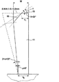
ブラシヘッドは、概して様々な方法で駆動され得る。歯ブラシ及びその駆動の構成に依存して、異なる駆動運動学を実施することができる。本発明の有利な更なる態様では、駆動運動は、毛支持体を通って延在する回転軸の周囲の振動回転運動を含む。本発明の有利な実施形態では、前記回転軸は、その中心点又は重心を通って毛支持体の平面に対して垂直に延在することができる。 The brush head can generally be driven in various ways. Depending on the toothbrush and its drive configuration, different drive kinematics can be implemented. In an advantageous further aspect of the invention, the drive movement comprises an oscillating rotational movement around a rotational axis extending through the bristle support. In an advantageous embodiment of the invention, the axis of rotation can extend perpendicular to the plane of the bristle carrier through its center point or center of gravity.
しかし、本発明の代替実施形態によると、回転軸が偏心に位置づけられることもまた可能であり、したがって、毛セクションの異なる周辺側において異なる強度の運動構成要素が生成される。本発明の有利な更なる態様では、この偏心は、外側のより長い毛房に適用され、すなわち、回転軸は、対向する外側のより長い房を通る接続線に対して平行に変位される。毛セクションの構成に依存して、偏心は、一方では異なる周辺側の所望の異なるサイズの洗浄動作と、他方では回転軸が毛支持体の直径線を55%〜45%から最高70%〜30%の長さ比率で分割するときに達成されるなお許容される振動と、を上手く妥協することによって様々に顕著にすることができる。 However, according to an alternative embodiment of the invention, it is also possible for the axis of rotation to be positioned eccentrically, thus producing different strength motion components on different peripheral sides of the bristle section. In an advantageous further aspect of the invention, this eccentricity is applied to the outer longer tuft, i.e. the axis of rotation is displaced parallel to the connecting line through the opposing outer longer tuft. Depending on the configuration of the bristle section, the eccentricity can occur on the one hand on different peripheral side desired different size cleaning operations and on the other hand the axis of rotation of the hair support diameter line from 55% to 45% up to 70% to 30%. Various prominences can be made by successfully compromising the still acceptable vibration achieved when dividing by the% length ratio.
あるいは、又は加えて、毛支持体の回転軸を、前記支持体によって画定された平面に対して鋭角に傾斜することが可能であり、傾斜角は、毛支持体の平面に対して好ましくは89°〜65°、特定すると88°〜82°の範囲内である。結果的に、毛セクションの溝形状の湾曲面の形状とともに、回転運動に打突運動を付加することが可能である。好ましくは、回転軸は、毛セクションが歯ブラシのハンドピースから傾いて離れるように傾けられる。これは、特に臼歯及び切歯の内側の面に関して、洗浄が難しい歯の区域への到達をより容易にする。 Alternatively or additionally, the axis of rotation of the bristle support can be inclined at an acute angle with respect to the plane defined by said support, the tilt angle being preferably 89 with respect to the plane of the bristle support. It is in the range of ° to 65 °, specifically 88 ° to 82 °. As a result, it is possible to add a striking motion to the rotational motion along with the shape of the groove-shaped curved surface of the bristle section. Preferably, the axis of rotation is tilted so that the bristle section tilts away from the toothbrush handpiece. This makes it easier to reach areas of the tooth that are difficult to clean, especially with respect to the inner surfaces of the molars and incisors.
本発明の更なる態様では、毛セクションの回転振動が与えられると、平面図で細長く見える、周方向に外側のより長い房の末端表面は、回転軸の周りで弧状に、具体的には回転軸の周りで円弧状に延びる。 In a further aspect of the invention, the circumferentially outer longer tuft end surface, which appears elongated in plan view when subjected to rotational vibration of the bristle section, is arcuate, specifically rotated around the axis of rotation. It extends in an arc around the axis.
本発明の更なる態様では、より長い外側毛房の外端上の前述の面取り部は、直線で延在することができるが、房の弧状に湾曲した細長い末端表面にほぼ接線方向に好ましくは延在できる。第一に、これは房の生産を簡易にする。また、これは、面取り部の幅及びそれと付随して面取りされていない末端表面に周方向の変化をもたらし、くさび形表面の様式においてこれは、隣接歯間への、対応する房の連続的な挿入と退出を引き起こすことができる。 In a further aspect of the invention, the aforementioned chamfer on the outer end of the longer outer tress can extend in a straight line but is preferably substantially tangential to the arcuately curved elongated end surface of the tress. Can be extended. First, it simplifies the production of bunches. This also results in a circumferential change in the width of the chamfer and the contiguous non-chamfered end surface, which in the form of a wedge-shaped surface is a continuous series of corresponding tufts between adjacent teeth. Can cause insertion and withdrawal.
しかし、本発明の別の実施形態によると、特に房の面取り部及び/又は残りの非面取り部の末端表面が、周方向に一定の輪郭及び幅を有するようにするために、面取り部が回転軸の周囲で同等に弧状湾曲に延在することもまた可能である。結果的に、歯側面への房の非常にやさしい接触及び隣接歯の間への好適又は均質な貫通が可能となる。 However, according to another embodiment of the invention, the chamfer is rotated, in particular so that the end surface of the chamfer and / or the rest of the non-chamfer has a constant contour and width in the circumferential direction. It is also possible to extend an arcuate curve equally around the axis. As a result, very gentle contact of the tufts on the tooth sides and suitable or homogeneous penetration between adjacent teeth is possible.
外側のより長い房は、毛セクション又は毛支持体の周辺の約25%〜75%を覆う距離に沿って内側の房を囲む。 The outer longer tuft surrounds the inner tuft along a distance that covers about 25-75% of the periphery of the hair section or hair support.
作業表面の前記中央のくぼみを画定する自由端を有する内側の房は、それらの自由端でほぼ連続した表面に形成することができ、したがって事実上連続した溝形状のくぼみをもたらすことができる。したがって、それは第一に、歯側面全面の包囲を達成することが可能であり、したがって、大きい区域にかけての洗浄効果が可能である。その一方で、それは歯磨剤又は歯洗浄剤の配置に有益な影響を有し、歯磨剤又は歯洗浄剤は、毛セクションの作業表面によりよく保持され、房間から毛支持体に流れ落ちにくくなる。 Inner tufts having free ends that define the central indentation of the working surface can be formed into a substantially continuous surface at those free ends, thus providing a substantially continuous groove-shaped indentation. Thus, it is possible first of all to achieve an encircling of the entire tooth flank and thus a cleaning effect over a large area is possible. On the other hand, it has a beneficial effect on the placement of the dentifrice or tooth cleaning agent, which is better retained on the working surface of the hair section and less likely to flow from the interflock to the hair support.
本発明の代替的な更なる態様では、前記内側の房は、それらの自由端によって、分離した末端表面を形成することが可能であり、その結果、緩んだ破片の排出をしやすくすることが可能になる。 In an alternative further aspect of the present invention, the inner tufts can form a separate end surface by their free ends, thereby facilitating the discharge of loose debris. It becomes possible.
本発明のこれら及び更なる特徴は、請求項の要約とは無関係に、単独で又は任意の二次的な組み合わせにおいて使用されたときに本発明の課題を形成することが可能であり、請求項からによってのみでなく、本発明の好ましい実施形態をより詳細に説明する後続の説明及び添付の図からもまた明確になるであろう。これらの図面では、 These and further features of the invention may form the subject of the invention when used alone or in any secondary combination, regardless of the summary of the claims. As well as from the following description and accompanying figures which describe the preferred embodiment of the invention in more detail. In these drawings,
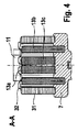
図1に示す代表的な電気歯ブラシ1は、ハンドルセクション2と、それに取り外し可能に連結されるように適応されるブラシヘッド4とを備える。ブラシヘッド4は、ハンドルセクション2に接続された歯ブラシ1の首セクション3を備えており、前記首セクション3は部分的に中空の管の形状に構成されている。
A typical electric toothbrush 1 shown in FIG. 1 includes a
ハンドルセクション2は、その内部に、好ましくは充電式電池の形態であるエネルギー源20と、好ましくは電気モーターの形態であるモーター5と、制御装置21とを収容する。
The
実施形態で示されるように、モーター5の回転運動は、伝動装置22の手段によって、首セクション3を通ってブラシヘッド4の遠位端まで延在するドライブシャフト23の振動回転運動に転換される。歯ブラシ1は、ハンドルセクション2上に装着されたスイッチ24によって起動及び停止することができる。
As shown in the embodiment, the rotational movement of the motor 5 is converted by means of a
好適な伝動装置(例えば、実施形態に示されているのと異なるベベルギヤ25)を使用する既知の方法で、ドライブシャフト23の末端で、ある毛支持材7を、歯ブラシの長手方向軸26に対して横方向にほぼ延びる回転軸9の周りで振動回転運動を駆動可能である。これが生じるにつれて、ブラシヘッド4の毛支持体7によって掃かれる角度範囲は、約±35°〜±5°の範囲の値を有し、また、±10°〜±100°の範囲の振動が可能である。振動周波数は、例えば10Hz〜100Hzの間で変動すること及びその間にあることができる。図1に示す実施形態では、回転軸9は歯ブラシの長手方向軸26と直角を成す。加えて、ブラシヘッド4の駆動は、回転又は振動の軸の方向への脈動のために、第3の次元に設けられる。
In a known manner using a suitable transmission (for example a
図2〜5は、歯ブラシ1のブラシヘッド4に使用するブラシ部の代表的な実施形態を示す。この実施形態では、毛支持体7は丸いが円形ではなく(ただし円形を除外しない)、わずかに卵形及び/又は楕円形であり、中立位の毛支持体7において卵形又は楕円形の長軸が歯ブラシの長手方向軸26に対して平行に延び、卵形又は楕円形の短軸はそれに対して横方向に延びる。図2において、卵形又は楕円形の長軸は線B−Bと平行である。
2 to 5 show typical embodiments of the brush portion used in the brush head 4 of the toothbrush 1. In this embodiment, the
毛支持体7上には複数の毛房が配列され、これらの毛房は、いくつかの輪12、14及び15に配列され、毛セクション10の上に拡がる。図2に図示された実施形態では、外側の輪12上には8つの外側毛房が配置されており、それらのうち4つは細長い輪郭を有するが、他の4つは概して丸い若しくは等辺の断面輪郭を有する。前記外側の輪12上の房の長さには変化があり、これについてはより詳細に説明するが、概して、より長い房は、セクター29及び30でなく、対向するセクター27及び28に概して設けられ、これらは毛支持体7の初期位置では歯ブラシの長手方向軸26を包含し、セクター29及び30はその横方向に配向される、すなわちそれらの間に置かれる(図2を参照)。
A plurality of tufts are arranged on the
図2に示すように、房11及び31は外側の輪12上に主軸B−B及びA−A上にそれぞれ置かれ、上面図で細長くなっており、一方、それらの間に置かれる房32はほぼ等辺の輪郭を有するか、又はほぼ立方体(cubic)若しくは丸い断面を有する。前記細長い房11及び31は、振動/回転軸9の周りに弧状に湾曲して延在する(図2を参照)。
As shown in FIG. 2,
この構造では、より長い主軸B−B上に置かれた外側毛房11は、周辺セクションの約50°〜90°にかけて、好ましくは約70°にかけて延在し、一方、より短い主軸A−Aに置かれた外側毛房31は、周辺セクションの、約20°〜45°にかけて、好ましくは約30°にかけて延在する。
In this construction, the
外側から見て第2の房の輪15上には、合計10の中間毛房13a及び13bが配置されており、そのいくつかは円形断面を有し、残りは角形の断面を有する。具体的には、円形断面を有する中間毛房13aは、図2に示されるように、外側の輪12のより長い外側毛房11が置かれているセクター27及び28に配列され、一方、角形の房は第2の輪14上に、毛支持体7の中間セクター29及び30に設けられる。また、第2の輪14上のこれらの中間毛房13a及び13bの長さは、短い主軸に置かれるセクター29及び30でなく前記セクター27及び28により長い房が設けられるように、輪14の周辺に沿って房から房へと周期的に変化する。
A total of ten
中間の輪14の丸い中間毛房13a及び角ばった、ほぼ正方形の(又は角形)中間毛房13bは、それらの異なった断面輪郭とは無関係に、だいたい少なくともほぼ同じ区域を有する。
The round
図2が示すように、毛房の固定のために好ましい隙間条件を設けるために、本発明の更なる態様では、中間リング14の角形の中間毛房13b(少なくともそれらのいくつか)を、毛支持体7の主軸A−A及びB−Bに対して、及びまた、それらが配列される輪14の環状輪郭に対して、鋭角に回転することができる。具体的には、角形の中間毛房の少なくとも1つ、好ましくは第2の角形の中間毛房13bの主軸は、毛房断面の主軸37が中間の輪14の接線に対して鋭角に傾斜されるように回転され得る。これによって、対応するアンカープレートは、他のアンカープレートの衝突範囲外に回転される。加えて、毛セクション全体の撓み作用を全体的により均一にすること、特に、方向への依存を少なくすることができる。
As FIG. 2 shows, in order to provide a favorable clearance condition for the fixation of the tufts, in a further aspect of the present invention, the square
最後に、外側から見て最も内側の区域又は第3の房の輪には、2つの細長い中央毛房13cが設けられ、これらは、より長い主軸B−Bに平行な長手方向軸38に沿って延在する。
Finally, the innermost section or the third tuft ring as seen from the outside is provided with two elongated
中央毛房13cは、中間の輪の中間毛房13a及び13bよりはるかに大きい断面積を有する。図の実施形態では、それらの断面積は中間の輪14の中間毛房13a及び13bの断面積の200%〜400%である。
The
この構造では、中央毛房13cは、それらの長手方向の寸法38がそれらの横方向の寸法の150%を超え、好ましくはほぼ150%〜300%である、細長い構成にある。図の実施形態では、中央毛房13cは有利にも外側輪郭が凸面形に湾曲し、内側輪郭が一直線であり、内側輪郭と外側輪郭とは有利にも丸い端部輪郭によって接続されている。したがって、代表的な中央毛房13cの全体的な形は、ほぼバナナ形である。これら2つのほぼ半月形の中央毛房13cは、それらが共になってほぼ楕円形の毛セクションを形成するようにそれらの形が互いを補完するように配列される。概して、2つの中央毛房の形は、ほぼ半月形又はバナナ形又は腎臓形であってよく、それらの形が互いを補完して、2つの中央毛房の周囲を包囲された引かれる凸面湾曲によって画定される概して丸い、例えば円形、卵形、又は楕円形の毛セクションを形成するように配列され得る。
In this configuration, the
示される中央毛房13cは、毛支持体の主軸に対して平行に整列された長手方向軸38を有し、毛支持体7の偏向されていない中立位においては、歯ブラシの長手方向軸26又はそれを通る長手方向中央平面に対して平行に延びる。それらの房は、その毛の末端で、実質的に均質の密に充填された毛末端表面を形成する。これは、中央毛房が互いに傾斜し合うように約1°〜2°の角度で回転軸の方へ内向きに傾けられたタフティング穴壁13dを設けることによって達成される。
The
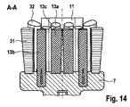
図3に示すように、毛セクション10の房は、それらの長さ及び/又は高さに関して互いに凹凸があるか、互いに協調した自由端を有し、したがって、それらの房の自由端によって画定される毛セクション10の作業表面34は溝形状の底17を有する中央のくぼみ16を有し、このくぼみは一方向において湾曲しており、それに対する垂直の方向においては真っ直ぐである。この湾曲は、有利にも、毛支持体7がその偏向されていない中立位にあるとき、より長い主軸B−Bの方向に、すなわち歯ブラシの長手方向軸26の方向に延在する。それに対する垂直の方向、すなわち毛支持体7がその偏向されていない中立位にあるときに毛支持体7の短い方の主軸A−Aに対して平行に、及び/又は、歯ブラシの長手方向軸26に対して横方向に、延びる方向においては、くぼみ16は図3に示すように真っ直ぐな輪郭を有する。
As shown in FIG. 3, the tufts of
中央のくぼみ16は様々な深さに構成され得る。本発明の有利な更なる態様において、くぼみ16の最も深い点は毛セクション10の最も高い点より約1mm〜3mm、好ましくは約2mm深いところに設定される。くぼみ16の底17の溝形状の輪郭は、概して異なる曲率を有することができる。図3〜5に示した実施形態では、8mm〜17mmの範囲、好ましくは約10mm〜14mmの範囲の曲率半径を有する円弧形の輪郭が設けられるが、これは、毛セクションの寸法及び構成に依存して変化し得る。
The
図3に示すように、同じように組み合わせて溝形状の底17を画定する中間及び中央毛房13a、13b、13cの末端表面、及びより短い外側毛房31の末端表面は、平面としてでなく、それら自体が同じように溝形に湾曲されたものとして、構成される。溝形状の湾曲した末端表面35は互いを補完するように組み合わされて、中央のくぼみ16の底17の前記溝形状の輪郭を形成する。具体的に述べると、回転軸9から主軸B−Bに平行な方向への距離が増すにつれて、中間毛房及び中央毛房13a〜13cの末端表面の傾斜は増す(図3を参照)。言い換えれば、横方向に延びる主軸A−A上に配列される毛房は、それらの自由端においてわずかに湾曲されるものの、毛支持体の表面に対して実質的に平行に整列し、一方、それらの自由端の傾斜は、前記主軸A−Aからの距離が増すにつれて増す。
As shown in FIG. 3, the end surfaces of the middle and
同じく図3に示すように、セクター27及び28において外側の輪12に配列される外側毛房11は、他の房より長く延びている、すなわちそれらより長く、そのため他の房を超えて突き出ている。この結果、中央のくぼみ16に対して一段の高さ上昇部(図3を参照)、すなわち、図3に示す実施形態では中央のくぼみ16は前記外側毛房11の末端表面と滑らかに合流しない。
As also shown in FIG. 3, the
毛支持体の中立位において歯ブラシの長手方向軸26を含む、対向するセクター27及び28における前記外側毛房11は、有利にも、房11の長手方向軸に対してほぼ垂直に配列される平坦なセクション19と、外側に向かう前記末端表面36に面取りされた面取り部18と、を含む末端表面36を有する。
The
図5に示すように、前記面取り部18は約20°〜60°、好ましくは約30°〜40°の範囲で角度γで延在する。面取り部18は有利にも、その対応する房11の幅Wのほぼ25%〜75%を覆う深さ及び幅である。この場合、幅Wは、房の自由端の領域における、その長手方向軸に垂直で、その面取り部18の長手方向に垂直の寸法であると理解される(図5を参照)。図5に示す実施形態では、面取り部は幅Wの約4分の1から4分の3(長手方向軸B−Bに沿って測定)にかけて延在する。
As shown in FIG. 5, the
前記より長い外側毛房11は、長手方向のセクションとして見たとき全体として台形構成である。房11の内側に置かれている側面は、毛支持体7によって画定される平面に対してほぼ垂直に延在するが、外側に置かれている側面は毛支持体7上の垂線に向かって約1.5°〜10°、好ましくは約3°〜5°の角度αで傾斜し、そのため、房11の断面はその自由端に向かって増す、すなわち、この房はその自由端に向かって広がる。結果的に、毛支持体7のサイズを制限しつつ、大きい作業表面を得ることができる。加えて、房11の自由端において、房11の面取り部18に対して好ましい幾何学的比率がもたらされる。
The longer
歯側面をできるだけ完全に抱くために、及び広い区域にかけてブラシの圧力を分布するために、及び歯磨剤又は同様のものを作業表面34に保持するために、房の自由端は、有利にも、毛支持体7によって画定される区域の少なくとも35%〜55%、好ましくは50%以上を占有する。図2に示すように、全ての房の伸張をともに合計すると、外側の輪12上の房は周辺セクションの約200°〜300°にかけて延在することができる。外側から見て2番目の輪14は、同様に、周辺に沿った全ての房をともに合計すると、全体で周辺のほぼ200°〜300°にかけて延在することができる。最も内側の房は、その全表面にかけて実質的に閉じられた区域を、有利にもそれらの自由端で覆うことができる。
In order to hold the tooth side as completely as possible and to distribute the pressure of the brush over a large area and to retain the dentifrice or the like on the working
図6〜8に示すブラシヘッド4の実施形態は、図2〜5の実施形態と実質的に対応するので、説明の重複を避けるために、対応する前述の説明を参照する。図6から8の実施形態が図2〜5の実施形態と実質的に異なる唯一の点は、中央の溝形状のくぼみ16の輪郭がやや深いことであり、このくぼみは、より小さい曲率半径で、房の外側の輪12上の細長くない房32の丸い輪郭全体の中及び上において、湾曲している。
The embodiment of the brush head 4 shown in FIGS. 6-8 substantially corresponds to the embodiment of FIGS. 2-5, so that reference is made to the corresponding description above to avoid duplication of description. The only point that the embodiment of FIGS. 6 to 8 differs substantially from the embodiment of FIGS. 2 to 5 is that the profile of the central groove-shaped
図9〜11に示すブラシヘッド4の他の実施形態は、図6〜8の実施形態と実質的に対応するので、説明の重複を避けるために、その前述の説明を参照する。先に述べた実施形態と異なり、偏向されていない中立位において歯ブラシの長手方向軸25を含む、毛支持体7のセクター27及び28におけるより長い外側毛房11は、より顕著な面取り部18を有し、それらは、隣接歯間へのこれらの房11のよりよい貫通を可能にするために、末端表面36の平坦なセクション19に対して55°の角度γで面取りされる。
Other embodiments of the brush head 4 shown in FIGS. 9-11 substantially correspond to the embodiments of FIGS. 6-8, so that reference is made to the previous description to avoid duplication of description. Unlike the previously described embodiment, the longer
一方、内側の房13のいくつか及び/又は全て、具体的には、自由端が中央のくぼみ16の溝形状の底を画定する中間毛房13b及び中央毛房13cは、特別に構成された自由端を有する。前記中間毛房13b及び中央毛房13cは、末端が広げられた長繊維を少なくとも部分的に含み、そのおかげで、それらの自由端において、いわば柔らかいパイル及び/フリースが生成され、その結果、歯磨剤は特にこの領域によく保持され、それらの房は歯面の表面のほぼ全面の周囲にぴったり沿う。
On the other hand, some and / or all of the
図12〜14に示す実施形態は、図9〜11の実施形態と実質的に対応するので、その前述の説明を参照する。前述の実施形態と異なり、くぼみ16の底17の同じ曲率に対して、くぼみ16の最も深い点と毛セクションの最も高い点との間の高さの最大差はより大きく、約2mmである。セクター27及び28の領域の毛の長さは異なる。これは、臼歯及び切歯の内側歯面へのよりよいアクセスを可能にする。加えて、毛の外側の傾斜は3°〜5°である。
The embodiment shown in FIGS. 12-14 substantially corresponds to the embodiment of FIGS. 9-11, so reference is made to the previous description thereof. Unlike the previous embodiment, for the same curvature of the bottom 17 of the
図15〜17のブラシヘッド4の他の実施形態は、図12〜14の前述の実施形態と実質的に対応するので、その前述の説明を参照する。前述の実施形態と異なり、毛支持体7の最も内側の輪15は、わずかに楕円の断面を実質的に有する、長手方向軸が主軸B−Bに対して平行に配向されている2つの、細長さの度合いが少ない房13cを含む。しかし、図17に示すように、前記最も内側の房13cは、より顕著なテーパーで広げられているので、それらの断面は自由端に向かって増す。図17に示すように、中間毛房及び中央毛房13a、13b、13cは約0°〜10°、好ましくは約1.5°〜5°の開始角度で広がって、それらの自由端の領域で2つの中央毛房13cがいわば合致して接合表面を形成する一方で、毛支持体7上のそれらの足元の末端では、それらの毛房は、互いに間隔を空けて配置される。
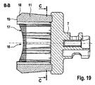
Other embodiments of the brush head 4 of FIGS. 15-17 substantially correspond to the previous embodiments of FIGS. 12-14 and reference is made to the previous description thereof. Unlike the previous embodiment, the
図18〜20に示す実施形態は、前述の図15〜17の実施形態と実質的に対応するので、その前述の説明を参照する。しかし、前述の実施形態と異なり、セクター27及び28の、より高い外側毛房11の面取り部18は異なる構成である。前述の実施形態の面取り部18は直線で延在し、すなわち、上面図で見られるように房11の弧状の形にも関わらず平面を画定するが、図18〜20の実施形態の面取り部18は弧状に湾曲しており、それらの面取り部18は房11の湾曲形に従って回転軸9の周りで同じように湾曲され、結果的に、房11の実質的に均一の面取りがもたらされる。より正確に述べると、面取り部18は房11の形を追従するので、房11は、それらのほぼ全長すなわちそれらの周方向の次元に沿って同量が面取りされる。これは、前述の他の実施形態にも適用され得る。
The embodiment shown in FIGS. 18-20 substantially corresponds to the embodiment of FIGS. 15-17 described above, so reference is made to the foregoing description. However, unlike the previous embodiment, the
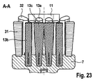
図21〜23に示す実施形態は、図12〜14の実施形態と実質的に対応するので、その前述の説明を参照する。図21〜23の実施形態では、より長い外側毛房11に対するくぼみ16は、図15〜17と比較してより深く作られ、したがって、くぼみ16の最も深い点と房11の最も高い点との間に約2mmの高さの差が生じる。
The embodiment shown in FIGS. 21-23 substantially corresponds to the embodiment of FIGS. 12-14, so reference is made to the previous description thereof. In the embodiment of FIGS. 21-23, the
図24〜26に示す実施形態は、前述の図18〜20の実施形態と実質的に対応するので、その前述の説明を参照する。前述の実施形態と比べて、くぼみ16はより長い外側毛房11に対してより深く作られ、したがって、高さにして約2mmの最大差が生じる。
The embodiment shown in FIGS. 24-26 substantially corresponds to the embodiment of FIGS. 18-20 described above, so reference is made to the foregoing description. Compared to the previous embodiment, the
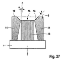
図27に示すように、セクター27及び28、並びにセクター29及び30にそれぞれ配列される、より長い外側毛房11及びより短い外側毛房31は(この場合、歯ブラシの長手方向軸26は、好ましくは、毛支持体7の偏向されていない中立位に置かれる)、その内側の側部すなわち回転軸に近い側にも面取り部18を有することができ、面取り部18の幅及び角度は前述の幾何学的比率にほぼ相当することができる。図27に示すように、房11の内側すなわち内側面に面取りが設けられる前記房11は、同じように台形であるが、支持体7上の垂線に向かって3°〜10°の範囲に鋭角に傾斜され、一方、外側面は支持体7に対してほぼ垂直に立っている。
As shown in FIG. 27, the longer
図28に示すように、より長い外側毛房11の内側の側部上の前記面取り18の結果として、それらの毛の自由端は歯側面の上反りの輪郭に特にぴったり沿って置かれる。
As shown in FIG. 28, as a result of the chamfering 18 on the inner side of the longer
内側の面取りを含む変異型は、歯肉の上の歯面の区域への洗浄効果を高める能力があるので、より短い外側毛房31と共に好ましい。
Variants that include an inner chamfer are preferred with shorter
本発明の以下の更なる態様は、別の実施形態において、及びこれらの請求項に具体的に特徴づけられる請求項の機構の特徴の補足として又はそれらから独立して、設ける。中央毛房の断面積が、中間領域に配列される毛房13a、13b、32の断面積の1倍から4倍の整数である、ブラシヘッド。ブラシヘッドは、中間毛房13a、13b、32の断面積が1.75±0.25mm2の範囲である。ブラシヘッドは、13a、13b、32に対する毛房11の断面積が4対1の比率であり、同時に、13a、13b、32に対する毛房31の断面積が2対1の比率である。ブラシヘッドは、毛房13c対13a、13b又は32の断面積の比率が2対1である。ブラシヘッドは、曲率が半径8〜17mm、又は好ましくは11〜14mmである円筒構成である。ブラシヘッドは、使用される毛が0.01〜0.025mm2の範囲の断面積又は4.5〜7ミルの直径を有する。ブラシヘッドは、平坦なセクション19に対する毛房11の毛の長さが8.55±0.25mmである。ブラシヘッドは、毛セクションのくぼみ16又は中央領域の、最も深い点に、最低でも6.85±0.25mmの毛の長さが設けられる。ブラシヘッドは、外側に対する、毛セクションの外側毛房11の毛の最大長が8.8±0.25mmであり、毛セクションの同じように外側の対向する毛房11の毛の最大長が8.15±0.25mmである。ブラシヘッドは、毛セクションの中央領域の毛が扇状に広がることができ、具体的には、毛の末端からのその扇状の広がりが1〜2.5mmの範囲内である。ブラシヘッドは、毛房11、31が、毛セクションの中央に面する内側上に面取り部18を含む。ブラシヘッドは、毛房が、その外側領域に(図5に図示するような)台形構造を有する。ブラシヘッドは、毛房31、32の鋭角(α)又は傾斜が、毛房11の角度より小さい。ブラシヘッドは、好ましくは支持体7に対して毛房11が3°の鋭角(α)であり、毛房31、32が直角である。ブラシヘッドは、全ての房の断面積の毛密度が支持体7の表面の35〜50%である。ブラシヘッドは、毛房13cの外側が支持体上の垂線に対して内向きに又は回転角に向かって1〜5°の鋭角に傾斜されている。
The following further aspects of the invention are provided in other embodiments and as a supplement to or independent of the features of the features of the claims specifically characterized by those claims. The brush head, wherein the cross-sectional area of the central tress is an integer of 1 to 4 times the cross-sectional area of the
本明細書に開示される寸法及び値は、列挙された正確な数値に厳しく制限されるものとして理解されるべきでない。それよりむしろ、特に指定されない限り、各こうした寸法は、列挙された値とその値周辺の機能的に同等の範囲の両方を意味することを意図する。例えば、「40mm」として開示される寸法は、「約40mm」を意味するものとする。 The dimensions and values disclosed herein are not to be understood as being strictly limited to the exact numerical values recited. Instead, unless otherwise specified, each such dimension is intended to mean both the recited value and a functionally equivalent range surrounding that value. For example, a dimension disclosed as “40 mm” shall mean “about 40 mm”.
相互参照される又は関連するあらゆる特許又は出願書類を含め、本明細書において引用される全ての文献は、明示的に除外ないしは制限されない限り、その全体を参考として本明細書に組み込まれる。いかなる文献の引用も、それが本明細書において開示され請求されるいずれかの発明に関する先行技術であること、又はそれが単独で若しくは他のいかなる参照とのいかなる組み合わせにおいても、このような発明を教示する、提案する、又は開示することを認めるものではない。更に、本書における用語のいずれかの意味又は定義が、参考として組み込まれた文献における同一の用語のいずれかの意味又は定義と相反する限りにおいて、本書においてその用語に与えられた定義又は意味が適用されるものとする。 All references cited herein, including any patents or application documents that are cross-referenced or related, are hereby incorporated by reference in their entirety, unless expressly excluded or limited. Citation of any document is such prior art as to any invention disclosed and claimed herein, or whether such reference alone or in any combination with any other reference. No teaching, suggestion, or disclosure is permitted. Furthermore, to the extent that any meaning or definition of a term in this document conflicts with any meaning or definition of the same term in a document incorporated by reference, the definition or meaning given to that term in this document applies. Shall be.
本発明の特定の実施形態について説明し記載したが、本発明の趣旨及び範囲から逸脱することなく他の様々な変更及び修正が可能であることが当業者には自明である。したがって、本発明の範囲内にあるそのようなすべての変更及び修正を、添付の書類名特許請求の範囲で扱うものとする。 While particular embodiments of the present invention have been illustrated and described, it would be obvious to those skilled in the art that various other changes and modifications can be made without departing from the spirit and scope of the invention. Accordingly, all such changes and modifications that are within the scope of this invention are intended to be covered by the appended claims.
Claims (19)
毛支持体(7)の可動式装着のための装着手段(8)を有する毛支持体(7)と、
前記毛支持体(7)上の互いに入れ子になった少なくとも2つの輪又は領域内に配列されている、複数の毛房(11、13a、13b、13c)と、を備え、
外側の輪(12)又は領域は、細長い房断面を有する外側毛房(11)を備え、前記外側毛房(11)は、前記外側の輪又は領域の対向する側に装着され、
前記外側の輪(12)又は領域内に入れ子になった中間の輪(14)又は領域は、前記外側毛房(11)の断面より小さい断面をそれぞれ有するいくつかの中間毛房(13a、13b)を備え、
前記中間の輪(14)又は領域の中央区域は、前記中間の輪(14)又は領域の前記中間毛房(13a、13b)の断面より大きい断面を有する2つの中央毛房(13c)からなる少なくとも1つの毛セクションを備え、前記中央毛房(13c)はそれぞれ、細長い形状、具体的には半月形、バナナ形、又は腎臓形の形状を有し、それらの形状が互いに補完し合うことにより、前記中央領域の毛セクションがほぼ円形、卵形、又は楕円形の構造を有する、電気歯ブラシ用のブラシヘッド。 A brush head for an electric toothbrush (1),
A hair support (7) having mounting means (8) for mobile mounting of the hair support (7);
A plurality of tufts (11, 13a, 13b, 13c) arranged in at least two rings or regions nested on each other on said hair support (7),
The outer ring (12) or region comprises an outer tress (11) having an elongated tuft cross section, the outer tress (11) being mounted on the opposite side of the outer ring or region,
The intermediate ring (14) or region nested within the outer ring (12) or region has a number of intermediate tresses (13a, 13b) each having a cross-section that is smaller than the cross-section of the outer tress (11). )
The middle zone of the intermediate ring (14) or region consists of two central hair tufts (13c) having a cross section that is larger than the cross section of the intermediate hair (13a, 13b) of the middle ring (14) or region. Each of the central tresses (13c) has an elongated shape, specifically a half-moon shape, a banana shape, or a kidney shape, and these shapes complement each other. A brush head for an electric toothbrush, wherein the bristle section of the central region has a generally circular, oval or elliptical structure.
毛支持体(7)の可動式装着のための装着手段(8)を有する毛支持体(7)と、
前記毛支持体(7)上に配列されている複数の毛房(11、13a、13b、13c)と、を備え、
前記毛支持体の中央区域は、前記中央区域に隣接する中間毛房(13a、13b)の断面より大きい断面を有する2つの中央毛房(13c)からなる少なくとも1つの毛セクションを備え、前記中央毛房(13c)はそれぞれ、細長い形状、具体的には半月形、バナナ形、又は腎臓形の形状を有し、それらの形状が互いに補完し合うことにより、前記中央領域の毛セクションがほぼ円形、卵形、又は楕円形の構造を有する、電気歯ブラシ用のブラシヘッド。 A brush head for an electric toothbrush (1),
A hair support (7) having mounting means (8) for mobile mounting of the hair support (7);
A plurality of tufts (11, 13a, 13b, 13c) arranged on the hair support (7),
Central zone of the bristle carrier comprises at least Tsunoke section consists of two central tufts (13c) having a larger cross-section than the cross section of Makebo (13a, 13b) in you adjacent said central region, Each of the central tresses (13c) has an elongated shape, specifically, a half-moon shape, a banana shape, or a kidney shape, and these shapes complement each other, so that the hair section in the central region becomes A brush head for an electric toothbrush having a generally circular, oval or elliptical structure.
Applications Claiming Priority (3)
| Application Number | Priority Date | Filing Date | Title |
|---|---|---|---|
| EP08019330A EP2184032A1 (en) | 2008-11-05 | 2008-11-05 | Electric toothbrush and brush head therefor |
| EP08019330.3 | 2008-11-05 | ||
| PCT/IB2009/054899 WO2010052653A1 (en) | 2008-11-05 | 2009-11-04 | Electric toothbrush and brush head for an electric toothbrush |
Publications (2)
| Publication Number | Publication Date |
|---|---|
| JP2012506752A JP2012506752A (en) | 2012-03-22 |
| JP5373097B2 true JP5373097B2 (en) | 2013-12-18 |
Family
ID=40551898
Family Applications (1)
| Application Number | Title | Priority Date | Filing Date |
|---|---|---|---|
| JP2011533924A Active JP5373097B2 (en) | 2008-11-05 | 2009-11-04 | Electric toothbrush and brush head for electric toothbrush |
Country Status (14)
| Country | Link |
|---|---|
| US (1) | US8813292B2 (en) |
| EP (2) | EP2184032A1 (en) |
| JP (1) | JP5373097B2 (en) |
| KR (1) | KR101365392B1 (en) |
| CN (1) | CN102202602B (en) |
| AU (1) | AU2009312455B2 (en) |
| BR (1) | BRPI0921643B8 (en) |
| CA (1) | CA2741832C (en) |
| DK (1) | DK2349069T3 (en) |
| ES (1) | ES2787549T3 (en) |
| MX (1) | MX2011004757A (en) |
| PL (1) | PL2349069T3 (en) |
| RU (1) | RU2485913C2 (en) |
| WO (1) | WO2010052653A1 (en) |
Families Citing this family (52)
| Publication number | Priority date | Publication date | Assignee | Title |
|---|---|---|---|---|
| JP2007172671A (en) * | 2005-09-30 | 2007-07-05 | Ricoh Co Ltd | Power determining method, single-sided multilayer optical disk, recording method, program, recording medium, and optical disk apparatus |
| US8484788B2 (en) * | 2011-03-14 | 2013-07-16 | L'oreal Sa | Brushhead for electric skin brush appliance |
| DE102011122106A1 (en) * | 2011-12-22 | 2013-06-27 | Carl Freudenberg Kg | Broom block with bristle structure |
| AU2013406764B2 (en) * | 2013-12-05 | 2016-12-22 | Colgate-Palmolive Company | Oral care implement with cover member |
| JP6446981B2 (en) * | 2014-10-09 | 2019-01-09 | サンスター株式会社 | Single tuft brush |
| US10182644B2 (en) | 2014-12-23 | 2019-01-22 | Colgate-Palmolive Company | Oral care implement |
| CA2970676A1 (en) | 2014-12-23 | 2016-06-30 | Colgate-Palmolive Company | Oral care implement |
| WO2016105372A1 (en) | 2014-12-23 | 2016-06-30 | Colgate-Palmolive Company | Oral care implement |
| RU2647813C1 (en) | 2014-12-23 | 2018-03-19 | Колгейт-Палмолив Компани | Oral care implement, having multi-component handle |
| AU2014414825B2 (en) | 2014-12-23 | 2018-04-12 | Colgate-Palmolive Company | Oral care implement |
| AU2014414810B2 (en) | 2014-12-23 | 2018-04-05 | Colgate-Palmolive Company | Oral care implement |
| US11291293B2 (en) | 2014-12-23 | 2022-04-05 | Colgate-Palmolive Company | Oral care implement |
| MX2017007626A (en) | 2014-12-23 | 2017-09-18 | Colgate Palmolive Co | Oral care implement. |
| USD780457S1 (en) | 2014-12-23 | 2017-03-07 | Colgate-Palmolive Company | Oral care implement |
| MX2017007842A (en) | 2014-12-23 | 2017-09-19 | Colgate Palmolive Co | Oral care implement having multi-component handle. |
| EP4023106A1 (en) | 2014-12-23 | 2022-07-06 | Colgate-Palmolive Company | Oral care implement |
| US10660430B2 (en) | 2014-12-23 | 2020-05-26 | Colgate-Palmolive Company | Oral care implement having multi-component handle |
| SE539869C2 (en) | 2016-01-14 | 2017-12-27 | Fosieborg Ab | Brush head and method of operating the brush head |
| USD802935S1 (en) * | 2016-03-09 | 2017-11-21 | Noksibcho Aloe Co., Ltd. | Electric toothbrush |
| USD812912S1 (en) * | 2016-05-06 | 2018-03-20 | Stefan Eidenbenz | Interdental cleaner |
| US10022025B2 (en) | 2016-05-20 | 2018-07-17 | Chirp Products, LLC | Dual motor cleansing brush |
| PL3272310T3 (en) * | 2016-07-22 | 2020-11-02 | Braun Gmbh | Brush head and electric toothbrush |
| USD830699S1 (en) | 2017-02-03 | 2018-10-16 | Harria Investment Group Ltd. | Brush head for an electric toothbrush |
| USD838990S1 (en) | 2017-05-11 | 2019-01-29 | Harria Investment Group Ltd | Brush head for an electric toothbrush |
| CN109223230B (en) | 2017-07-11 | 2020-09-25 | Js控股股份有限公司 | Removable brush head for a power toothbrush |
| US11241083B2 (en) | 2017-07-13 | 2022-02-08 | Chirp Products, LLC | Cleansing brush head |
| EP3461367B1 (en) | 2017-09-28 | 2020-04-22 | The Procter & Gamble Company | Method of making a unitary brush head and unitary toothbrush head |
| CA3021410C (en) * | 2017-10-27 | 2023-12-12 | Sunstar Americas, Inc. | Powered toothbrush bristle head |
| EP3479733A1 (en) * | 2017-11-02 | 2019-05-08 | Braun GmbH | Brush head for an oral care implement |
| US10709533B2 (en) | 2017-12-12 | 2020-07-14 | Colgate-Palmolive Company | Oral care implement and handle and refill head thereof |
| US10631964B2 (en) | 2017-12-12 | 2020-04-28 | Colgate-Palmolive Company | Oral care implement |
| CN304701695S (en) | 2017-12-21 | 2018-06-29 | ||
| USD898369S1 (en) | 2018-10-09 | 2020-10-13 | World Wide Daily Holdings Company Limited | Toothbrush |
| USD897684S1 (en) | 2018-10-09 | 2020-10-06 | World Wide Daily Holdings Company Limited | Toothbrush |
| USD898370S1 (en) | 2018-10-09 | 2020-10-13 | World Wide Daily Holdings Company Limited | Toothbrush |
| USD898371S1 (en) | 2018-11-16 | 2020-10-13 | World Wide Daily Holdings Company Limited | Toothbrush |
| USD897685S1 (en) | 2018-11-16 | 2020-10-06 | World Wide Daily Holdings Company Limited | Toothbrush |
| USD885060S1 (en) * | 2018-11-29 | 2020-05-26 | Afuw Llc | Toothbrush head |
| BR112021010824B1 (en) * | 2018-12-13 | 2023-11-21 | Colgate-Palmolive Company | INSTRUMENT FOR ORAL HYGIENE |
| EP3893694A4 (en) | 2018-12-13 | 2022-10-12 | Colgate-Palmolive Company | Oral care implement |
| USD927191S1 (en) | 2018-12-14 | 2021-08-10 | World Wide Daily Holdings Company Limited | Toothbrush |
| USD897687S1 (en) | 2018-12-14 | 2020-10-06 | World Wide Daily Holdings Company Limited | Toothbrush |
| USD897686S1 (en) | 2018-12-14 | 2020-10-06 | World Wide Daily Holdings Company Limited | Toothbrush |
| USD891784S1 (en) | 2018-12-18 | 2020-08-04 | Colgate-Palmolive Company | Electric toothbrush handle |
| USD898372S1 (en) | 2019-01-10 | 2020-10-13 | World Wide Daily Holdings Company Limited | Toothbrush |
| USD906687S1 (en) | 2019-01-10 | 2021-01-05 | World Wide Daily Holdings Company Limited | Toothbrush |
| CN111480970B (en) * | 2020-03-31 | 2022-07-01 | 北京小米移动软件有限公司 | Toothbrush, toothbrush control method and toothbrush control system |
| USD961269S1 (en) | 2020-07-31 | 2022-08-23 | Colgate-Palmolive Company | Oral care implement |
| USD960582S1 (en) | 2020-12-10 | 2022-08-16 | Colgate-Palmolive Company | Oral care refill head |
| CN112972040A (en) * | 2021-02-08 | 2021-06-18 | 好维股份有限公司 | Electric toothbrush head and manufacturing method thereof |
| CN113576150B (en) * | 2021-07-31 | 2023-07-21 | 好维股份有限公司 | Toothbrush head and toothbrush with clean polishing tooth face function |
| USD962650S1 (en) * | 2022-01-27 | 2022-09-06 | Shenzhen E-WORLD Technology Limited | Electric toothbrush head |
Family Cites Families (35)
| Publication number | Priority date | Publication date | Assignee | Title |
|---|---|---|---|---|
| DE19523016C5 (en) * | 1995-06-24 | 2005-04-07 | Braun Gmbh | Brush part for an electric toothbrush |
| US6058541A (en) * | 1996-07-03 | 2000-05-09 | Gillette Canada Inc. | Crimped bristle toothbrush |
| MXPA01013220A (en) * | 1999-07-02 | 2002-06-04 | Unilever Nv | Electric toothbrush. |
| AU2001272072A1 (en) * | 2000-02-15 | 2001-08-27 | Smithkline Beecham Gmbh & Co. Kg | Brush part for an electric toothbrush |
| DE10015062B4 (en) * | 2000-03-25 | 2010-05-12 | Braun Gmbh | Brush head and method of making such a brush head |
| DE10044031A1 (en) * | 2000-09-06 | 2002-03-21 | Braun Gmbh | Motorized toothbrush and brush head therefor |
| USD455556S1 (en) | 2000-12-27 | 2002-04-16 | Braun Gmbh | Battery toothbrush |
| US6735804B2 (en) * | 2001-01-12 | 2004-05-18 | Conair Corporation | Toothbrush bristle disk |
| US20020138926A1 (en) * | 2001-04-02 | 2002-10-03 | Braun Gmbh | Electric toothbrush head |
| DE10123258A1 (en) * | 2001-05-12 | 2002-11-21 | Braun Gmbh | toothbrush head |
| US6848141B2 (en) * | 2001-06-08 | 2005-02-01 | Colgate-Palmolive Company | Brush section for an electric toothbrush |
| DE10211391A1 (en) * | 2002-03-15 | 2003-10-02 | Braun Gmbh | Electric toothbrush and toothbrush head therefor |
| AU151174S (en) | 2002-03-22 | 2003-03-21 | Braun G M B H | Toothbrush head |
| WO2004000155A1 (en) * | 2002-06-20 | 2003-12-31 | Unilever N.V. | Electric toothbrush |
| US7089621B2 (en) * | 2002-09-20 | 2006-08-15 | Colgate-Palmolive Company | Toothbrush |
| DE10253532A1 (en) * | 2002-11-16 | 2004-05-27 | Braun Gmbh | Electric toothbrush, comprising two individually moving bristle carrying areas, driven by shared mechanism |
| CN2614048Y (en) * | 2003-05-09 | 2004-05-05 | 戴晓国 | Electric toothbrush |
| US7941886B2 (en) * | 2003-09-19 | 2011-05-17 | Braun Gmbh | Toothbrushes |
| KR100577105B1 (en) * | 2004-03-16 | 2006-05-08 | 주식회사 베스트화성 | Functional toothbrush |
| USD517325S1 (en) | 2004-04-30 | 2006-03-21 | Koninklijke Philips Electronics | Toothbrush head and neck unit with dispensing valves |
| US8317424B2 (en) * | 2004-06-03 | 2012-11-27 | The Gillette Company | Oral care device |
| JP4854280B2 (en) * | 2005-11-29 | 2012-01-18 | 花王株式会社 | toothbrush |
| DE202008004017U1 (en) * | 2007-12-13 | 2008-06-12 | Häusler, Wolfgang | Brush head for a toothbrush |
| DE202007017676U1 (en) * | 2007-12-13 | 2008-03-06 | Häusler, Wolfgang | Brush head for a toothbrush |
| EP2348916A1 (en) * | 2008-08-24 | 2011-08-03 | Hadasit Medical Research Services And Development Ltd. | A maneuvarable bristle toothbrush |
| EP2186434B1 (en) * | 2008-11-05 | 2016-10-12 | Braun GmbH | Toothbrush, brush and brush head for a toothbrush |
| EP2184031A1 (en) * | 2008-11-05 | 2010-05-12 | Braun Gmbh | Electric toothbrush and brush head |
| EP2184033A1 (en) * | 2008-11-05 | 2010-05-12 | Braun Gmbh | Electrical tooth brush and its brush body |
| USD611711S1 (en) * | 2008-11-06 | 2010-03-16 | The Procter & Gamble Company | Toothbrush head |
| USD606316S1 (en) * | 2008-11-06 | 2009-12-22 | The Procter & Gamble Company | Toothbrush head |
| USD606758S1 (en) * | 2008-11-06 | 2009-12-29 | The Procter & Gamble Company | Toothbrush head |
| USD606318S1 (en) * | 2008-11-06 | 2009-12-22 | The Procter & Gamble Company | Toothbrush head |
| EP2409598B1 (en) * | 2010-07-22 | 2018-09-26 | Braun GmbH | Method for producing a toothbrush head |
| PL2543277T3 (en) * | 2011-07-06 | 2016-12-30 | Cleaning section for an electric oral hygiene device | |
| EP2729035A1 (en) * | 2011-07-06 | 2014-05-14 | Braun GmbH | Cleaning section for an electric oral hygiene device |
-
2008
- 2008-11-05 EP EP08019330A patent/EP2184032A1/en not_active Withdrawn
-
2009
- 2009-11-04 PL PL09759799T patent/PL2349069T3/en unknown
- 2009-11-04 BR BRPI0921643A patent/BRPI0921643B8/en active IP Right Grant
- 2009-11-04 RU RU2011117020/14A patent/RU2485913C2/en active
- 2009-11-04 AU AU2009312455A patent/AU2009312455B2/en active Active
- 2009-11-04 MX MX2011004757A patent/MX2011004757A/en active IP Right Grant
- 2009-11-04 EP EP09759799.1A patent/EP2349069B1/en active Active
- 2009-11-04 ES ES09759799T patent/ES2787549T3/en active Active
- 2009-11-04 JP JP2011533924A patent/JP5373097B2/en active Active
- 2009-11-04 DK DK09759799.1T patent/DK2349069T3/en active
- 2009-11-04 CA CA2741832A patent/CA2741832C/en active Active
- 2009-11-04 KR KR1020117010235A patent/KR101365392B1/en active IP Right Grant
- 2009-11-04 WO PCT/IB2009/054899 patent/WO2010052653A1/en active Application Filing
- 2009-11-04 CN CN2009801440684A patent/CN102202602B/en active Active
-
2011
- 2011-05-02 US US13/098,692 patent/US8813292B2/en active Active
Also Published As
| Publication number | Publication date |
|---|---|
| AU2009312455B2 (en) | 2014-09-04 |
| CN102202602B (en) | 2013-07-10 |
| RU2485913C2 (en) | 2013-06-27 |
| EP2349069A1 (en) | 2011-08-03 |
| PL2349069T3 (en) | 2020-07-13 |
| US20110239391A1 (en) | 2011-10-06 |
| EP2349069B1 (en) | 2020-02-12 |
| KR101365392B1 (en) | 2014-02-19 |
| KR20110081278A (en) | 2011-07-13 |
| US8813292B2 (en) | 2014-08-26 |
| EP2184032A1 (en) | 2010-05-12 |
| AU2009312455A1 (en) | 2010-05-14 |
| BRPI0921643B1 (en) | 2020-01-21 |
| CN102202602A (en) | 2011-09-28 |
| ES2787549T3 (en) | 2020-10-16 |
| RU2011117020A (en) | 2012-12-20 |
| JP2012506752A (en) | 2012-03-22 |
| WO2010052653A1 (en) | 2010-05-14 |
| BRPI0921643A2 (en) | 2016-02-10 |
| DK2349069T3 (en) | 2020-05-04 |
| CA2741832C (en) | 2014-05-20 |
| BRPI0921643B8 (en) | 2021-06-22 |
| CA2741832A1 (en) | 2010-05-14 |
| MX2011004757A (en) | 2011-06-01 |
Similar Documents
| Publication | Publication Date | Title |
|---|---|---|
| JP5373097B2 (en) | Electric toothbrush and brush head for electric toothbrush | |
| JP5373098B2 (en) | Electric toothbrush and brush head for electric toothbrush | |
| KR101340759B1 (en) | Electric toothbrush and brush head for an electric toothbrush | |
| US20120036654A1 (en) | Toothbrush and bristle and brush head for a toothbrush |
Legal Events
| Date | Code | Title | Description |
|---|---|---|---|
| A977 | Report on retrieval |
Free format text: JAPANESE INTERMEDIATE CODE: A971007 Effective date: 20130131 |
|
| A131 | Notification of reasons for refusal |
Free format text: JAPANESE INTERMEDIATE CODE: A131 Effective date: 20130205 |
|
| A601 | Written request for extension of time |
Free format text: JAPANESE INTERMEDIATE CODE: A601 Effective date: 20130502 |
|
| A602 | Written permission of extension of time |
Free format text: JAPANESE INTERMEDIATE CODE: A602 Effective date: 20130513 |
|
| A601 | Written request for extension of time |
Free format text: JAPANESE INTERMEDIATE CODE: A601 Effective date: 20130605 |
|
| A602 | Written permission of extension of time |
Free format text: JAPANESE INTERMEDIATE CODE: A602 Effective date: 20130612 |
|
| A601 | Written request for extension of time |
Free format text: JAPANESE INTERMEDIATE CODE: A601 Effective date: 20130705 |
|
| A602 | Written permission of extension of time |
Free format text: JAPANESE INTERMEDIATE CODE: A602 Effective date: 20130712 |
|
| A521 | Request for written amendment filed |
Free format text: JAPANESE INTERMEDIATE CODE: A523 Effective date: 20130801 |
|
| TRDD | Decision of grant or rejection written | ||
| A01 | Written decision to grant a patent or to grant a registration (utility model) |
Free format text: JAPANESE INTERMEDIATE CODE: A01 Effective date: 20130823 |
|
| A61 | First payment of annual fees (during grant procedure) |
Free format text: JAPANESE INTERMEDIATE CODE: A61 Effective date: 20130918 |
|
| R150 | Certificate of patent or registration of utility model |
Ref document number: 5373097 Country of ref document: JP Free format text: JAPANESE INTERMEDIATE CODE: R150 Free format text: JAPANESE INTERMEDIATE CODE: R150 |
|
| R250 | Receipt of annual fees |
Free format text: JAPANESE INTERMEDIATE CODE: R250 |
|
| R250 | Receipt of annual fees |
Free format text: JAPANESE INTERMEDIATE CODE: R250 |
|
| R250 | Receipt of annual fees |
Free format text: JAPANESE INTERMEDIATE CODE: R250 |
|
| R250 | Receipt of annual fees |
Free format text: JAPANESE INTERMEDIATE CODE: R250 |
|
| R250 | Receipt of annual fees |
Free format text: JAPANESE INTERMEDIATE CODE: R250 |
|
| R250 | Receipt of annual fees |
Free format text: JAPANESE INTERMEDIATE CODE: R250 |
|
| R250 | Receipt of annual fees |
Free format text: JAPANESE INTERMEDIATE CODE: R250 |
|
| R250 | Receipt of annual fees |
Free format text: JAPANESE INTERMEDIATE CODE: R250 |