JP5371663B2 - Pattern drawing apparatus and pattern drawing method - Google Patents

Pattern drawing apparatus and pattern drawing method Download PDF

Info

Publication number
JP5371663B2
JP5371663B2 JP2009224348A JP2009224348A JP5371663B2 JP 5371663 B2 JP5371663 B2 JP 5371663B2 JP 2009224348 A JP2009224348 A JP 2009224348A JP 2009224348 A JP2009224348 A JP 2009224348A JP 5371663 B2 JP5371663 B2 JP 5371663B2
Authority
JP
Japan
Prior art keywords
detection
distance
signal
main scanning
pattern
Prior art date
Legal status (The legal status is an assumption and is not a legal conclusion. Google has not performed a legal analysis and makes no representation as to the accuracy of the status listed.)
Active
Application number
JP2009224348A
Other languages
Japanese (ja)
Other versions
JP2011075635A (en
Inventor
均 熱田
武史 陶山
Current Assignee (The listed assignees may be inaccurate. Google has not performed a legal analysis and makes no representation or warranty as to the accuracy of the list.)
Screen Holdings Co Ltd
Dainippon Screen Manufacturing Co Ltd
Original Assignee
Screen Holdings Co Ltd
Dainippon Screen Manufacturing Co Ltd
Priority date (The priority date is an assumption and is not a legal conclusion. Google has not performed a legal analysis and makes no representation as to the accuracy of the date listed.)
Filing date
Publication date
Application filed by Screen Holdings Co Ltd, Dainippon Screen Manufacturing Co Ltd filed Critical Screen Holdings Co Ltd
Priority to JP2009224348A priority Critical patent/JP5371663B2/en
Publication of JP2011075635A publication Critical patent/JP2011075635A/en
Application granted granted Critical
Publication of JP5371663B2 publication Critical patent/JP5371663B2/en
Active legal-status Critical Current
Anticipated expiration legal-status Critical

Links

Images

Abstract

<P>PROBLEM TO BE SOLVED: To align the focus position of a light beam onto the principal plane of a substrate with high precision in each main scanning. <P>SOLUTION: A pattern drawing apparatus includes a distance detecting part 5 acquiring a detected distance to the principal plane of a substrate 9, and a focusing mechanism 471 adjusting the focus of the light beam from a head. When drawing a pattern in a linear area extending in a main scanning direction in each main scanning which represents an outward route or a return route, a plurality of detected distances are obtained with respect to the linear area where a pattern is to be drawn in the next main scanning; and the focus adjustment is performed in a plurality of times by using the plurality of detected distances obtained in the last main scanning. A control part 6 controls in such a manner that, in terms of the main scanning direction, detection positions where a plurality of detected distances are obtained in each of the outward route and the return route coincide with a plurality of positions of irradiation areas when the focus adjustment in a plurality of times is completed, and that the detection positions of the plurality of detected distances in the outward route and the return route are approximated. Thereby, the focus position of a light beam in each main scanning aligned with the principal plane with high precision. <P>COPYRIGHT: (C)2011,JPO&amp;INPIT

Description

本発明は、基板にパターンを描画する技術に関する。   The present invention relates to a technique for drawing a pattern on a substrate.

従来より、感光レジスト膜を有する基板の主面上にて、光変調素子からの光ビームの照射領域を走査することにより、マスクを用いることなく基板上にパターンを描画するパターン描画装置(マスクレス露光装置とも呼ばれる。)が実用化されている。このようなパターン描画装置においてパターンを高精度に描画するには、光ビームの合焦位置を基板の主面上に精度よく合わせる必要がある。   Conventionally, a pattern drawing apparatus (maskless) for drawing a pattern on a substrate without using a mask by scanning an irradiation region of a light beam from a light modulation element on the main surface of the substrate having a photosensitive resist film. It is also called an exposure apparatus). In order to draw a pattern with high accuracy in such a pattern drawing apparatus, it is necessary to accurately align the focus position of the light beam on the main surface of the substrate.

そこで、特許文献1の装置では、スキャナの下方を通過する感光材料を、スキャナから照射されるレーザー光によって走査露光する際に、被露光面との距離を測定するフォーカス測定用の変位センサをスキャナの上流側に配置することにより、変位センサによる距離測定結果に基づいて光ビームの焦点位置を被露光面に一致させる手法が開示されている。また、特許文献1では、感光材料を走査方向に沿った方向へ往復移動させる際に、感光材料の往路移動において距離測定を行い、感光材料の復路移動において露光を行う手法も開示されている。   Therefore, in the apparatus of Patent Document 1, when a photosensitive material passing under the scanner is subjected to scanning exposure with laser light emitted from the scanner, a displacement sensor for focus measurement that measures the distance from the exposed surface is used as the scanner. A method is disclosed in which the focal position of the light beam coincides with the surface to be exposed based on the distance measurement result by the displacement sensor. Japanese Patent Application Laid-Open No. 2004-228561 also discloses a method of performing distance measurement in the forward movement of the photosensitive material and performing exposure in the backward movement of the photosensitive material when the photosensitive material is reciprocated in the direction along the scanning direction.

特開2005−266779号公報Japanese Patent Laying-Open No. 2005-266779

ところで、基板上に高精細なパターンを描画する際には、空間変調される光ビームの基板上における照射領域を小さくし、照射領域を所定の方向に連続的に相対移動する主走査と、照射領域を主走査の方向に垂直な方向へと間欠的に相対移動する副走査とが交互に繰り返される。この場合に、パターンを短時間にて描画するには、主走査方向に関して照射領域の往路および復路のそれぞれにてパターンの描画を行う必要があり、往路において距離測定のみを行い、復路において当該距離測定の結果を用いてフォーカス調整を行いつつパターンを描画する特許文献1の手法は採用することができない。したがって、各主走査において光ビーム等のエネルギービームの合焦位置を基板の主面上に精度よく合わせることが可能な新規な手法が必要となる。   By the way, when a high-definition pattern is drawn on the substrate, the irradiation area on the substrate of the light beam to be spatially modulated is reduced, the main scanning for continuously moving the irradiation area in a predetermined direction, and irradiation Sub-scanning, in which the area is intermittently relatively moved in the direction perpendicular to the main scanning direction, is alternately repeated. In this case, in order to draw the pattern in a short time, it is necessary to draw the pattern in each of the outgoing path and the backward path of the irradiation region in the main scanning direction. The method of Patent Document 1 that draws a pattern while performing focus adjustment using the measurement result cannot be employed. Therefore, a new method is required that can accurately align the focus position of an energy beam such as a light beam on the main surface of the substrate in each main scan.

本発明は上記課題に鑑みなされたものであり、各主走査においてエネルギービームの合焦位置を基板の主面上に精度よく合わせることを目的としている。   The present invention has been made in view of the above problems, and an object of the present invention is to accurately align the focus position of the energy beam on the main surface of the substrate in each main scan.

請求項1に記載の発明は、基板にパターンを描画するパターン描画装置であって、基板を保持する保持部と、前記基板の主面に変調可能なエネルギービームを照射するヘッドと、前記エネルギービームの合焦位置を前記主面上に合わせるフォーカス調整を行うフォーカス機構と、前記主面に垂直な方向に関して前記主面との間の距離を検出距離として取得する距離検出部と、往路および復路のそれぞれにおいて前記主面上にて主走査方向に伸びる線状領域にパターンを描画するため、前記保持部を前記ヘッドおよび前記距離検出部に対して相対的に前記主走査方向に往復移動する主走査機構と、前記主走査方向に関して前記ヘッドおよび前記距離検出部に対する前記保持部の相対的な位置を測定する位置測定部と、前記主走査方向に垂直かつ前記主面に平行な副走査方向に前記保持部を前記ヘッドおよび前記距離検出部に対して相対的に移動する副走査機構と、一の主走査による線状領域へのパターンの描画が完了する毎に、前記保持部の前記副走査方向への相対移動、および、前記一の主走査時とは反対の進行方向への前記保持部の相対移動を順に行って前記線状領域に平行な他の線状領域へのパターンの描画を行うとともに、各主走査時に距離検出パルス信号および駆動開始パルス信号を前記距離検出部および前記フォーカス機構に入力して複数の検出距離の取得および複数回のフォーカス調整を行う制御部とを備え、前記主面上において前記エネルギービームの照射領域と、前記検出距離が取得される検出領域とが前記主走査方向に所定の照射−検出間距離だけ離れており、前記各主走査にてパターンが描画される線状領域に対する前記複数の検出距離が、前記各主走査とは反対の進行方向となるN回前の主走査(ただし、Nは1以上の奇数)にて前記距離検出部により取得されるように、前記照射領域と前記検出領域とが前記副走査方向にも離れており、前記制御部において、前記フォーカス機構への前記駆動開始パルス信号の入力からフォーカス調整の完了までの時間に相当する前記保持部の相対移動距離が駆動遅延距離として設定されるとともに、前記主走査方向に関して前記往路における前記複数の検出距離の検出位置と、前記復路における前記複数の検出距離の検出位置とが近似するように、前記往路および前記復路におけるパルス信号入力の能動化を示す往路パルス入力ON信号、および、復路パルス入力ON信号の前記主走査方向における発生位置も設定されており、前記制御部が、前記検出領域が前記照射領域よりも先行する前記往路において、前記往路パルス入力ON信号の発生をトリガとして前記位置測定部の出力に基づいて一定のピッチにて前記距離検出パルス信号を繰り返し発生し、前記照射−検出間距離から前記駆動遅延距離を減じた距離だけ各距離検出パルス信号の発生位置から進行方向前側の位置にて前記駆動開始パルス信号を発生し、前記照射領域が前記検出領域よりも先行する前記復路において、前記復路パルス入力ON信号の発生をトリガとして前記位置測定部の出力に基づいて前記一定のピッチにて前記駆動開始パルス信号を繰り返し発生し、前記照射−検出間距離に前記駆動遅延距離を加えた距離だけ各駆動開始パルス信号の発生位置から進行方向前側の位置にて前記距離検出パルス信号を発生することにより、前記各主走査において前記N回前の主走査にて取得される前記複数の検出距離を用いて前記複数回のフォーカス調整が行われる。   The invention according to claim 1 is a pattern drawing apparatus that draws a pattern on a substrate, a holding unit that holds the substrate, a head that irradiates a main surface of the substrate with a modifiable energy beam, and the energy beam. A focus mechanism that adjusts the in-focus position on the main surface, a distance detection unit that acquires a distance from the main surface as a detection distance in a direction perpendicular to the main surface, and a forward path and a return path Main scanning for reciprocating the holder in the main scanning direction relative to the head and the distance detecting unit in order to draw a pattern in a linear region extending in the main scanning direction on the main surface. A mechanism, a position measuring unit for measuring a relative position of the holding unit with respect to the head and the distance detecting unit with respect to the main scanning direction, and a direction perpendicular to the main scanning direction and A sub-scanning mechanism that moves the holding unit relative to the head and the distance detection unit in a sub-scanning direction parallel to the main surface and drawing of a pattern in a linear region by one main scanning are completed. Each time, the relative movement of the holding part in the sub-scanning direction and the relative movement of the holding part in the moving direction opposite to that of the one main scanning are sequentially performed, and the parallel movement to the linear region is performed. In addition to drawing a pattern in the linear region, a distance detection pulse signal and a drive start pulse signal are input to the distance detection unit and the focus mechanism during each main scan to acquire a plurality of detection distances and perform multiple focus operations A control unit that performs adjustment, and the irradiation region of the energy beam on the main surface and the detection region where the detection distance is acquired are separated by a predetermined irradiation-detection distance in the main scanning direction, The main scanning before N times when the plurality of detection distances with respect to the linear region where the pattern is drawn in each main scanning is in the traveling direction opposite to the main scanning (where N is an odd number of 1 or more) The irradiation area and the detection area are also separated from each other in the sub-scanning direction as acquired by the distance detection unit at the control unit, and from the input of the drive start pulse signal to the focus mechanism in the control unit The relative movement distance of the holding unit corresponding to the time until the focus adjustment is completed is set as a drive delay distance, the detection positions of the plurality of detection distances in the forward path with respect to the main scanning direction, and the plurality of detection positions in the return path The forward pulse input ON signal indicating activation of the pulse signal input in the forward path and the backward path, and the backward pulse input so that the detection position of the detection distance of The generation position of the force ON signal in the main scanning direction is also set, and the control unit triggers generation of the forward pulse input ON signal in the forward path where the detection area precedes the irradiation area. The distance detection pulse signal is repeatedly generated at a constant pitch based on the output of the measurement unit, and the front side in the traveling direction from the generation position of each distance detection pulse signal by a distance obtained by subtracting the drive delay distance from the irradiation-detection distance. The drive start pulse signal is generated at the position of the predetermined time, and in the return path where the irradiation area precedes the detection area, the generation of the return pulse input ON signal is used as a trigger based on the output of the position measurement unit. The drive start pulse signal is repeatedly generated at a pitch of, and each drive is started by a distance obtained by adding the drive delay distance to the irradiation-detection distance. By generating the distance detection pulse signal at a position on the front side in the traveling direction from the generation position of the pulse signal, the plurality of detection distances acquired in the main scan N times before in each main scan are used. Multiple focus adjustments are performed.

請求項2に記載の発明は、請求項1に記載のパターン描画装置であって、前記往路および前記復路のそれぞれにおけるパルス入力ON信号の発生位置の決定処理において、前記制御部が、前記往路および前記復路の一方の経路に関して、任意に決定されたパルス入力ON信号の発生位置にて一の線状領域に対する前記複数の検出距離を取得し、前記往路および前記復路の他方の経路に関して、パルス入力ON信号の発生位置を前記一定のピッチよりも小さい間隔にて複数通りに変更して、前記パルス入力ON信号の各発生位置に関して前記一の線状領域に対する前記複数の検出距離を取得し、前記パルス入力ON信号の前記各発生位置に関する前記複数の検出距離と、前記一方の経路における前記複数の検出距離との差に基づいて、前記他方の経路におけるパルス入力ON信号の発生位置が決定される。   Invention of Claim 2 is the pattern drawing apparatus of Claim 1, Comprising: In the determination process of the generation | occurrence | production position of the pulse input ON signal in each of the said outward path and the said return path, the said control part is the said outbound path | route and With respect to one path of the return path, the plurality of detection distances with respect to one linear region are acquired at a position where a pulse input ON signal is arbitrarily determined, and pulse input is performed with respect to the other path of the forward path and the return path Changing the generation position of the ON signal in a plurality of ways at intervals smaller than the fixed pitch, obtaining the plurality of detection distances for the one linear region with respect to each generation position of the pulse input ON signal, Based on the difference between the plurality of detection distances relating to the respective generation positions of the pulse input ON signal and the plurality of detection distances in the one path, the other Occurrence position of the pulse input ON signal in the path is determined.

請求項3に記載の発明は、請求項2に記載のパターン描画装置であって、前記主走査機構における移動速度を変更する際に、前記パルス入力ON信号の発生位置の決定処理が行われる。   According to a third aspect of the present invention, in the pattern drawing apparatus according to the second aspect, when the moving speed in the main scanning mechanism is changed, the generation position of the pulse input ON signal is determined.

請求項4に記載の発明は、請求項1ないし3のいずれかに記載のパターン描画装置であって、前記N回前の主走査が直前の主走査である。   A fourth aspect of the present invention is the pattern drawing apparatus according to any one of the first to third aspects, wherein the main scanning before N times is the main scanning immediately before.

請求項5に記載の発明は、パターン描画装置を用いて基板にパターンを描画するパターン描画方法であって、前記パターン描画装置が、基板を保持する保持部と、前記基板の主面に変調可能なエネルギービームを照射するヘッドと、前記エネルギービームの合焦位置を前記主面上に合わせるフォーカス調整を行うフォーカス機構と、前記主面に垂直な方向に関して前記主面との間の距離を検出距離として取得する距離検出部と、往路および復路のそれぞれにおいて前記主面上にて主走査方向に伸びる線状領域にパターンを描画するため、前記保持部を前記ヘッドおよび前記距離検出部に対して相対的に前記主走査方向に往復移動する主走査機構と、前記主走査方向に関して前記ヘッドおよび前記距離検出部に対する前記保持部の相対的な位置を測定する位置測定部と、前記主走査方向に垂直かつ前記主面に平行な副走査方向に前記保持部を前記ヘッドおよび前記距離検出部に対して相対的に移動する副走査機構と、一の主走査による線状領域へのパターンの描画が完了する毎に、前記保持部の前記副走査方向への相対移動、および、前記一の主走査時とは反対の進行方向への前記保持部の相対移動を順に行って前記線状領域に平行な他の線状領域へのパターンの描画を行うとともに、各主走査時に距離検出パルス信号および駆動開始パルス信号を前記距離検出部および前記フォーカス機構に入力して複数の検出距離の取得および複数回のフォーカス調整を行う制御部とを備え、前記主面上において前記エネルギービームの照射領域と、前記検出距離が取得される検出領域とが前記主走査方向に所定の照射−検出間距離だけ離れており、前記各主走査にてパターンが描画される線状領域に対する前記複数の検出距離が、前記各主走査とは反対の進行方向となるN回前の主走査(ただし、Nは1以上の奇数)にて前記距離検出部により取得されるように、前記照射領域と前記検出領域とが前記副走査方向にも離れており、前記パターン描画方法が、a)前記フォーカス機構への前記駆動開始パルス信号の入力からフォーカス調整の完了までの時間に相当する前記保持部の相対移動距離を駆動遅延距離として決定する工程と、b)前記主走査方向に関して前記往路における前記複数の検出距離の検出位置と、前記復路における前記複数の検出距離の検出位置とが近似するように、前記往路および前記復路におけるパルス信号入力の能動化を示す往路パルス入力ON信号、および、復路パルス入力ON信号の前記主走査方向における発生位置を決定する工程と、c)前記基板上にパターンを描画する工程とを備え、前記c)工程において、前記制御部が、前記検出領域が前記照射領域よりも先行する前記往路において、前記往路パルス入力ON信号の発生をトリガとして前記位置測定部の出力に基づいて一定のピッチにて前記距離検出パルス信号を繰り返し発生し、前記照射−検出間距離から前記駆動遅延距離を減じた距離だけ各距離検出パルス信号の発生位置から進行方向前側の位置にて前記駆動開始パルス信号を発生し、前記照射領域が前記検出領域よりも先行する前記復路において、前記復路パルス入力ON信号の発生をトリガとして前記位置測定部の出力に基づいて前記一定のピッチにて前記駆動開始パルス信号を繰り返し発生し、前記照射−検出間距離に前記駆動遅延距離を加えた距離だけ各駆動開始パルス信号の発生位置から進行方向前側の位置にて前記距離検出パルス信号を発生することにより、前記各主走査において前記N回前の主走査にて取得される前記複数の検出距離を用いて前記複数回のフォーカス調整が行われる。   The invention according to claim 5 is a pattern drawing method for drawing a pattern on a substrate using a pattern drawing device, wherein the pattern drawing device can modulate a holding portion for holding a substrate and a main surface of the substrate. A distance between the head for irradiating a main energy beam, a focus mechanism for adjusting a focus position of the energy beam on the main surface, and the main surface in a direction perpendicular to the main surface. And the distance detecting unit acquired as a relative to the head and the distance detecting unit to draw a pattern in a linear region extending in the main scanning direction on the main surface in each of the forward path and the return path A main scanning mechanism that reciprocally moves in the main scanning direction, and a relative position of the holding unit with respect to the head and the distance detection unit with respect to the main scanning direction. A position measuring unit for measuring, a sub-scanning mechanism for moving the holding unit relative to the head and the distance detecting unit in a sub-scanning direction perpendicular to the main scanning direction and parallel to the main surface, Each time the drawing of the pattern in the linear region by the main scanning is completed, the relative movement of the holding unit in the sub-scanning direction and the movement of the holding unit in the advancing direction opposite to the time of the one main scanning are performed. Relative movement is sequentially performed to draw a pattern on another linear region parallel to the linear region, and a distance detection pulse signal and a drive start pulse signal are sent to the distance detection unit and the focus mechanism during each main scan. A control unit that inputs and acquires a plurality of detection distances and performs focus adjustments a plurality of times, and the main region is irradiated with the energy beam and the detection region where the detection distance is acquired. N which is separated by a predetermined irradiation-detection distance in the inspection direction, and the plurality of detection distances with respect to the linear region in which the pattern is drawn in each main scanning is a traveling direction opposite to each main scanning. The irradiation area and the detection area are also separated in the sub-scanning direction so as to be acquired by the distance detection unit in the main scan before the rotation (where N is an odd number of 1 or more), and the pattern drawing A) determining a relative movement distance of the holding portion corresponding to a time from input of the drive start pulse signal to the focus mechanism to completion of focus adjustment as a drive delay distance; and b) the main scanning. In order to approximate the detection positions of the plurality of detection distances on the forward path and the detection positions of the plurality of detection distances on the return path with respect to the direction, A step of determining a generation position of the forward pulse input ON signal indicating activation and a backward pulse input ON signal in the main scanning direction; and c) drawing a pattern on the substrate. The control unit detects the distance at a constant pitch based on the output of the position measurement unit, triggered by the generation of the forward pulse input ON signal, in the forward path where the detection area precedes the irradiation area. A pulse signal is repeatedly generated, and the drive start pulse signal is generated at a position in front of the traveling direction from the generation position of each distance detection pulse signal by a distance obtained by subtracting the drive delay distance from the irradiation-detection distance, and the irradiation Based on the output of the position measurement unit, triggered by the generation of the return pulse input ON signal in the return path where the area precedes the detection area The drive start pulse signal is repeatedly generated at the constant pitch, and the distance at the position on the front side in the traveling direction from the generation position of each drive start pulse signal by a distance obtained by adding the drive delay distance to the irradiation-detection distance. By generating the detection pulse signal, the focus adjustment is performed a plurality of times using the plurality of detection distances acquired in the main scan N times before in each main scan.

請求項6に記載の発明は、請求項5に記載のパターン描画方法であって、前記b)工程が、b1)前記往路および前記復路の一方の経路に関して、任意に決定されたパルス入力ON信号の発生位置にて一の線状領域に対する前記複数の検出距離を取得する工程と、b2)前記往路および前記復路の他方の経路に関して、パルス入力ON信号の発生位置を前記一定のピッチよりも小さい間隔にて複数通りに変更して、前記パルス入力ON信号の各発生位置に関して前記一の線状領域に対する前記複数の検出距離を取得する工程と、b3)前記パルス入力ON信号の前記各発生位置に関する前記複数の検出距離と、前記一方の経路における前記複数の検出距離との差に基づいて、前記他方の経路におけるパルス入力ON信号の発生位置を決定する工程とを備える。   A sixth aspect of the present invention is the pattern drawing method according to the fifth aspect, wherein the step b) is a pulse input ON signal arbitrarily determined with respect to one of the forward path and the backward path. A step of obtaining the plurality of detection distances for one linear region at the position of occurrence of b, and b2) with respect to the other path of the forward path and the return path, the generation position of the pulse input ON signal is smaller than the constant pitch. A plurality of detection distances with respect to the one linear region with respect to each generation position of the pulse input ON signal, and b3) each generation position of the pulse input ON signal. The position where the pulse input ON signal is generated in the other path is determined based on the difference between the plurality of detected distances related to the first path and the plurality of detected distances in the one path. And a degree.

請求項7に記載の発明は、請求項6に記載のパターン描画方法であって、前記主走査機構における移動速度を変更する際に、前記b1)ないしb3)工程が行われる。   A seventh aspect of the present invention is the pattern drawing method according to the sixth aspect, wherein the steps b1) to b3) are performed when the moving speed in the main scanning mechanism is changed.

請求項8に記載の発明は、請求項5ないし7のいずれかに記載のパターン描画方法であって、前記N回前の主走査が直前の主走査である。   The invention according to claim 8 is the pattern drawing method according to any one of claims 5 to 7, wherein the main scan before N times is the main scan immediately before.

本発明によれば、各主走査においてエネルギービームの合焦位置を基板の主面上に精度よく合わせることができる。   According to the present invention, the focus position of the energy beam can be accurately adjusted on the main surface of the substrate in each main scan.

また、請求項2および6の発明では、往路および復路のパルス入力ON信号の発生位置を精度よく決定することができ、請求項3および7の発明では、主走査機構における移動速度を変更する場合に、往路および復路のパルス入力ON信号の発生位置を容易に決定することができる。   In the inventions of claims 2 and 6, the generation positions of the forward and return pulse input ON signals can be determined with high accuracy. In the inventions of claims 3 and 7, the moving speed in the main scanning mechanism is changed. In addition, it is possible to easily determine the generation position of the pulse input ON signal for the forward path and the backward path.

パターン描画装置の側面図である。It is a side view of a pattern drawing apparatus. パターン描画装置の平面図である。It is a top view of a pattern drawing apparatus. 距離検出部および制御部の構成を示す図である。It is a figure which shows the structure of a distance detection part and a control part. 基板上における照射領域および検出領域を示す図である。It is a figure which shows the irradiation area | region and detection area | region on a board | substrate. 基板上にパターンを描画する動作の流れを示す図である。It is a figure which shows the flow of the operation | movement which draws a pattern on a board | substrate. 照射領域および検出領域の相対移動を説明するための図である。It is a figure for demonstrating the relative movement of an irradiation area | region and a detection area. 制御部によるタイミング制御を説明するための図である。It is a figure for demonstrating the timing control by a control part. パターン描画動作の事前処理の流れを示す図である。It is a figure which shows the flow of the pre-processing of pattern drawing operation | movement.

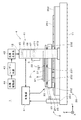
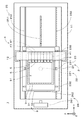
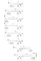
図1は本発明の一の実施の形態に係るパターン描画装置1の側面図であり、図2はパターン描画装置1の平面図である。パターン描画装置1は、基板9上の感光材料に光ビームを照射して当該感光材料に配線等のパターンを描画するパターン描画装置である。   FIG. 1 is a side view of a pattern drawing apparatus 1 according to an embodiment of the present invention, and FIG. 2 is a plan view of the pattern drawing apparatus 1. The pattern drawing apparatus 1 is a pattern drawing apparatus that draws a pattern such as wiring on the photosensitive material by irradiating the photosensitive material on the substrate 9 with a light beam.

図1および図2に示すように、パターン描画装置1は、(+Z)側の主面91(以下、「上面91」という。)上に感光材料の層が形成された基板9を保持する基板保持部3、基台11上に設けられて基板保持部3をZ方向に垂直なX方向およびY方向に移動する保持部移動機構2、基板保持部3および保持部移動機構2を跨ぐように基台11に固定されるフレーム12、フレーム12に取り付けられて基板9上の感光材料に変調された光を照射する光照射部4、光照射部4の(−Y)側にて基板9の主面91のZ方向の高さを検出する複数の(実際には、後述の光学ヘッド41と同数の)距離検出部5、並びに、保持部移動機構2や光照射部4等の各構成を制御する制御部6を備える。   As shown in FIGS. 1 and 2, the pattern writing apparatus 1 is a substrate that holds a substrate 9 on which a layer of a photosensitive material is formed on a main surface 91 (hereinafter referred to as “upper surface 91”) on the (+ Z) side. The holding unit 3 is provided on the base 11 so as to straddle the holding unit moving mechanism 2 that moves the substrate holding unit 3 in the X direction and the Y direction perpendicular to the Z direction, and the substrate holding unit 3 and the holding unit moving mechanism 2. A frame 12 fixed to the base 11, a light irradiation unit 4 attached to the frame 12 to irradiate modulated light onto the photosensitive material on the substrate 9, and the substrate 9 on the (−Y) side of the light irradiation unit 4. A plurality of (in fact, the same number of optical heads 41 as will be described later) distance detection units 5 that detect the height of the main surface 91 in the Z direction, and the holding unit moving mechanism 2 and the light irradiation unit 4 are configured. The control part 6 to control is provided.

基板保持部3は、基板9が載置されるステージ31、ステージ31を回転可能に支持する支持プレート33、および、支持プレート33上において、基板9の上面91に垂直な回転軸321を中心としてステージ31を回転するステージ回転機構32を備える。   The substrate holding unit 3 has a stage 31 on which the substrate 9 is placed, a support plate 33 that rotatably supports the stage 31, and a rotation axis 321 perpendicular to the upper surface 91 of the substrate 9 on the support plate 33. A stage rotation mechanism 32 that rotates the stage 31 is provided.

保持部移動機構2は、基板保持部3を図1および図2中のX方向(以下、「副走査方向」という。)に移動する副走査機構23、副走査機構23を介して支持プレート33を支持するベースプレート24、並びに、基板保持部3をベースプレート24と共にX方向に垂直なY方向(以下、「主走査方向」という。)に連続的に移動する主走査機構25を備える。パターン描画装置1では、保持部移動機構2により、基板9の上面91に平行な主走査方向および副走査方向に基板保持部3が移動される。   The holding unit moving mechanism 2 includes a sub-scanning mechanism 23 that moves the substrate holding unit 3 in the X direction in FIGS. 1 and 2 (hereinafter referred to as “sub-scanning direction”), and a support plate 33 via the sub-scanning mechanism 23. And a main scanning mechanism 25 that continuously moves the substrate holder 3 together with the base plate 24 in the Y direction perpendicular to the X direction (hereinafter referred to as “main scanning direction”). In the pattern drawing apparatus 1, the substrate holder 3 is moved in the main scanning direction and the sub-scanning direction parallel to the upper surface 91 of the substrate 9 by the holding unit moving mechanism 2.

図1および図2に示すように、副走査機構23は、支持プレート33の下側(すなわち、(−Z)側)において、ステージ31の主面に平行、かつ、主走査方向に垂直な副走査方向に伸びるリニアモータ231、並びに、リニアモータ231の(+Y)側および(−Y)側において副走査方向に伸びる一対のリニアガイド232を備える。主走査機構25は、ベースプレート24の下側において、ステージ31の主面に平行な主走査方向に伸びるリニアモータ251、並びに、リニアモータ251の(+X)側および(−X)側において主走査方向に伸びる一対のエアスライダ252を備える。   As shown in FIGS. 1 and 2, the sub-scanning mechanism 23 is arranged on the lower side of the support plate 33 (that is, on the (−Z) side) parallel to the main surface of the stage 31 and perpendicular to the main scanning direction. A linear motor 231 extending in the scanning direction and a pair of linear guides 232 extending in the sub-scanning direction on the (+ Y) side and the (−Y) side of the linear motor 231 are provided. The main scanning mechanism 25 has a linear motor 251 extending in a main scanning direction parallel to the main surface of the stage 31 below the base plate 24, and a main scanning direction on the (+ X) side and the (−X) side of the linear motor 251. A pair of air sliders 252 extending in the direction.

保持部移動機構2は、ステージ31の主走査方向の位置を測定する位置測定部26をさらに備える。レーザー測長器である位置測定部26は、レーザー光源、リニア干渉系およびレシーバを有する測定部本体261、並びに、ベースプレート24の(−Y)側の側面に取り付けられるミラー262を有し、基台11上に取り付けられる測定部本体261のレーザー光源から出射されたレーザー光はリニア干渉系を介してミラー262に入射し、ミラー262からの反射光が測定部本体261に入射する。測定部本体261では、反射光と、リニア干渉系にて参照光として利用される元のレーザー光の一部との干渉光がレシーバにより受光される。そして、レシーバからの出力(すなわち、反射光と参照光との干渉後の強度変化)に基づいて専用の演算回路により、ベースプレート24上のステージ31の主走査方向における位置がリアルタイムにて精度よく求められる。   The holding unit moving mechanism 2 further includes a position measuring unit 26 that measures the position of the stage 31 in the main scanning direction. The position measuring unit 26 which is a laser length measuring device has a measuring unit main body 261 having a laser light source, a linear interference system and a receiver, and a mirror 262 attached to the side surface on the (−Y) side of the base plate 24. 11 is incident on the mirror 262 via the linear interference system, and the reflected light from the mirror 262 is incident on the measurement unit main body 261. In the measurement unit main body 261, interference light between the reflected light and part of the original laser light used as reference light in the linear interference system is received by the receiver. Based on the output from the receiver (that is, the intensity change after interference between the reflected light and the reference light), the position of the stage 31 on the base plate 24 in the main scanning direction is accurately obtained in real time by a dedicated arithmetic circuit. It is done.

図2に示すように、光照射部4は、副走査方向に沿って等ピッチにて配列されてフレーム12に取り付けられる複数(本実施の形態では、8つ)の光学ヘッド41を備える。また、光照射部4は、図1に示すように、各光学ヘッド41に接続される光源光学系42、並びに、レーザー光を出射するレーザー光源43および光源駆動部44を備える。レーザー光源43は固体レーザーであり、光源駆動部44が駆動されることにより、レーザー光源43からレーザー光が出射され、光源光学系42を介して光学ヘッド41へと導かれる。   As shown in FIG. 2, the light irradiation unit 4 includes a plurality (eight in the present embodiment) of optical heads 41 arranged at an equal pitch along the sub-scanning direction and attached to the frame 12. As shown in FIG. 1, the light irradiation unit 4 includes a light source optical system 42 connected to each optical head 41, a laser light source 43 that emits laser light, and a light source driving unit 44. The laser light source 43 is a solid laser, and when the light source driving unit 44 is driven, laser light is emitted from the laser light source 43 and guided to the optical head 41 via the light source optical system 42.

各光学ヘッド41は、レーザー光源43からの光を下方に向けて出射する出射部45、出射部45からの光を反射して空間光変調器46へと導く光学系451、光学系451を介して照射された出射部45からの光を変調しつつ反射する空間光変調器46、および、空間光変調器46からの変調された光を基板9の上面91に設けられた感光材料上へと導く投影光学系47を備える。   Each optical head 41 emits light from the laser light source 43 downward, an optical unit 451 that reflects the light from the output unit 45 and guides it to the spatial light modulator 46, and an optical system 451. The spatial light modulator 46 that reflects and modulates the light emitted from the emitting portion 45, and the modulated light from the spatial light modulator 46 onto the photosensitive material provided on the upper surface 91 of the substrate 9. A projection optical system 47 is provided.

空間光変調器46は、出射部45を介して照射されたレーザー光源43からの光を基板9の上面91へと導く回折格子型の複数の光変調素子を備える。光変調素子は半導体装置製造技術を利用して製造され、格子の深さを変更することができる回折格子となっている。回折格子型の光変調素子としては、例えば、GLV(Grating Light Valve:グレーチング・ライト・バルブ)(シリコン・ライト・マシーンズの登録商標)が知られている。   The spatial light modulator 46 includes a plurality of diffraction grating type light modulation elements that guide light from the laser light source 43 irradiated through the emitting unit 45 to the upper surface 91 of the substrate 9. The light modulation element is manufactured using a semiconductor device manufacturing technique, and is a diffraction grating capable of changing the depth of the grating. For example, GLV (Grating Light Valve) (registered trademark of Silicon Light Machines) is known as a diffraction grating type light modulation element.

図1に示す光照射部4では、レーザー光源43からの光が光源光学系42により線状光(光束断面が線状の光)とされ、出射部45を介して空間光変調器46のライン状に配列された複数の光変調素子上に照射される。光変調素子は、入射光の反射光を0次光(正反射光)として導出する状態と、1次回折光(さらには、高次回折光)として導出する状態との間にて遷移可能とされる。光変調素子から出射される0次光は投影光学系47へと導かれ、非0次回折光(主として1次回折光((+1)次回折光および(−1)次回折光))は投影光学系47とは異なる方向へと導かれる。なお、迷光となることを防止するために1次回折光は図示を省略する遮光部により遮光される。   In the light irradiation unit 4 shown in FIG. 1, the light from the laser light source 43 is converted into linear light (light having a linear beam cross section) by the light source optical system 42, and the line of the spatial light modulator 46 is passed through the emission unit 45. Irradiation is performed on a plurality of light modulation elements arranged in a shape. The light modulation element can transition between a state in which reflected light of incident light is derived as zero-order light (regular reflection light) and a state in which light is derived as first-order diffracted light (and higher-order diffracted light). . The 0th-order light emitted from the light modulation element is guided to the projection optical system 47, and the non-zeroth-order diffracted light (mainly the first-order diffracted light ((+1) th-order diffracted light and (−1) th-order diffracted light)) and the projection optical system 47 Are guided in different directions. In order to prevent stray light from being generated, the first-order diffracted light is shielded by a light shielding unit (not shown).

光変調素子からの0次光は、投影光学系47を介して基板9の上面91へと導かれ、これにより、基板9の上面91上においてX方向(すなわち、副走査方向)に沿っておよそ直線状に並ぶ複数の領域のそれぞれに変調された光(光の強度がおよそ0とされる場合を含む。)が照射される。投影光学系47には、対物レンズ472を光軸に沿って移動するアクチュエータ(例えば、ピエゾアクチュエータ)を有するフォーカス機構471が設けられており、フォーカス機構471により光変調素子からのビーム状の光(光ビーム)の合焦位置が基板9の主面91上に合わせられる。なお、光変調素子からの1次回折光が基板9の上面91へと導かれ、0次光が遮光部により遮光されてもよい。   The zero-order light from the light modulation element is guided to the upper surface 91 of the substrate 9 via the projection optical system 47, and thereby approximately along the X direction (that is, the sub-scanning direction) on the upper surface 91 of the substrate 9. Each of the plurality of regions arranged in a straight line is irradiated with modulated light (including the case where the light intensity is approximately zero). The projection optical system 47 is provided with a focus mechanism 471 having an actuator (for example, a piezo actuator) that moves the objective lens 472 along the optical axis. The focus mechanism 471 causes beam-like light (from the light modulation element) ( The focusing position of the light beam is aligned on the main surface 91 of the substrate 9. The first-order diffracted light from the light modulation element may be guided to the upper surface 91 of the substrate 9 and the zero-order light may be shielded by the light shielding portion.

図1および図2に示すパターン描画装置1では、保持部移動機構2の主走査機構25により主走査方向に一定の速度にて移動される基板9に対し、光照射部4の光変調素子から変調された光が照射される。換言すれば、主走査機構25は、複数の光学ヘッド41を一体的に、かつ、基板9に対して相対的に連続移動して、複数の光学ヘッド41からの光が照射される複数の照射領域を、基板9に対して相対的にかつ連続的に主走査方向へと移動する移動機構となっている。   In the pattern drawing apparatus 1 shown in FIG. 1 and FIG. 2, from the light modulation element of the light irradiation unit 4 to the substrate 9 moved at a constant speed in the main scanning direction by the main scanning mechanism 25 of the holding unit moving mechanism 2. The modulated light is irradiated. In other words, the main scanning mechanism 25 moves the plurality of optical heads 41 integrally and relatively continuously with respect to the substrate 9 to irradiate light from the plurality of optical heads 41. This is a moving mechanism that moves the region in the main scanning direction relatively and continuously with respect to the substrate 9.

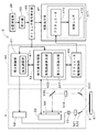
図3は、距離検出部5および制御部6の構成を示す図である。制御部6は、位置測定部26に接続されるとともに、ステージ31の主走査方向の位置を示す情報を受け付ける受付部66を有する。受付部66はタイミング信号発生部65に接続されており、タイミング信号発生部65では、入力されるステージ31の位置情報に基づいて、後述のパルス入力ON信号、距離検出パルス信号および駆動開始パルス信号(後述の図7参照)、並びに、ステージ31の移動方向を示す信号が生成される。   FIG. 3 is a diagram illustrating the configuration of the distance detection unit 5 and the control unit 6. The control unit 6 is connected to the position measurement unit 26 and has a reception unit 66 that receives information indicating the position of the stage 31 in the main scanning direction. The accepting unit 66 is connected to a timing signal generating unit 65. The timing signal generating unit 65, based on the input position information of the stage 31, inputs a pulse input ON signal, a distance detection pulse signal, and a drive start pulse signal, which will be described later. (See FIG. 7 described later) and a signal indicating the moving direction of the stage 31 is generated.

距離検出部5は、距離検出用の光を出射するレーザーダイオード光源51(以下、「LD光源51」という。)、および、LD光源51に接続されたLD駆動部52を有する。LD駆動部52は、制御部6の投光制御部61に接続され、投光制御部61の光量調整部611の制御によりLD光源51から所定の周期およびデューティ比にてパルス光が出射される。LD光源51からの光はレンズ531およびミラー532を介して基板9上に照射される。以下の説明では、LD光源51からの光が照射される基板9上の領域を「検出領域」という。なお、LD光源51からの光は、基板9上の感光材料を感光させない波長帯および強度となっている。   The distance detection unit 5 includes a laser diode light source 51 (hereinafter, referred to as “LD light source 51”) that emits light for distance detection, and an LD driving unit 52 connected to the LD light source 51. The LD driving unit 52 is connected to the light projecting control unit 61 of the control unit 6, and pulsed light is emitted from the LD light source 51 at a predetermined cycle and duty ratio under the control of the light amount adjusting unit 611 of the light projecting control unit 61. . Light from the LD light source 51 is irradiated onto the substrate 9 through the lens 531 and the mirror 532. In the following description, an area on the substrate 9 irradiated with light from the LD light source 51 is referred to as a “detection area”. Note that the light from the LD light source 51 has a wavelength band and intensity at which the photosensitive material on the substrate 9 is not exposed.

当該光の検出領域における反射光は、ミラー533にて反射されてレンズ534に取り込まれ、ミラー535を介して受光部であるラインセンサ54上に照射される。ラインセンサ54は、例えば、所定の方向に複数の画素が並ぶCCD(Charge Coupled Device)イメージセンサ、または、CMOS(Complementary Metal Oxide Semiconductor)イメージセンサであり、ラインセンサ54により基板9からの反射光の光量分布(ラインセンサ54の画素の配列方向における光量分布)が取得される。このとき、ラインセンサ54における出力が適切な大きさとなるように、LD光源51からのパルス光のデューティ比が設定されている。   The reflected light in the light detection region is reflected by the mirror 533 and taken into the lens 534, and is irradiated onto the line sensor 54 as a light receiving unit via the mirror 535. The line sensor 54 is, for example, a CCD (Charge Coupled Device) image sensor or a CMOS (Complementary Metal Oxide Semiconductor) image sensor in which a plurality of pixels are arranged in a predetermined direction. The line sensor 54 reflects reflected light from the substrate 9. A light amount distribution (a light amount distribution in the arrangement direction of the pixels of the line sensor 54) is acquired. At this time, the duty ratio of the pulsed light from the LD light source 51 is set so that the output from the line sensor 54 has an appropriate magnitude.

ラインセンサ54は受光制御部55に接続されており、ラインセンサ54からのアナログ出力信号は受光制御部55内にてA/D変換されて、デジタルの受光出力データが制御部6の検出信号処理部62に出力される。実際には、受光制御部55により、ラインセンサ54からの受光出力データの出力タイミングが一定の周期となるように制御される。また、ラインセンサ54からの出力タイミングに同期して、後述の処理にて参照されるラインセンサ54の有効な画素範囲を示す有効画素範囲信号が、検出信号処理部62に出力される。   The line sensor 54 is connected to the light reception control unit 55, the analog output signal from the line sensor 54 is A / D converted in the light reception control unit 55, and the digital light reception output data is detected by the control unit 6. Is output to the unit 62. Actually, the light reception control unit 55 controls the output timing of the light reception output data from the line sensor 54 to have a constant cycle. In addition, in synchronization with the output timing from the line sensor 54, an effective pixel range signal indicating an effective pixel range of the line sensor 54 referred to in the processing described later is output to the detection signal processing unit 62.

検出信号処理部62の重心位置算出部621では、タイミング信号発生部65から一定の周期にて入力される距離検出パルス信号に同期して、距離検出パルス信号の周期よりも短い周期にて順次入力される受光出力データがラッチされ、当該受光出力データが示す光量分布のピーク部分の重心位置(すなわち、光量分布において光量が急激に増大する位置と急激に減少する位置との間の部分における重心位置)が求められる。このとき、有効画素範囲信号に基づいて、ラインセンサ54の有効な画素範囲外の光量は無視される。そして、求められた重心位置は、距離検出パルス信号の発生時における基板9上の検出領域の主走査方向の位置(または、ステージ31の主走査方向の位置)に対応付けられて図示省略のメモリに記憶される。   In the center-of-gravity position calculation unit 621 of the detection signal processing unit 62, sequentially input at a cycle shorter than the cycle of the distance detection pulse signal in synchronization with the distance detection pulse signal input at a constant cycle from the timing signal generation unit 65. Received light output data is latched, and the barycentric position of the peak portion of the light quantity distribution indicated by the received light output data (that is, the barycentric position in the part between the position where the light quantity rapidly increases and the position where the light quantity rapidly decreases in the light quantity distribution) ) Is required. At this time, the light amount outside the effective pixel range of the line sensor 54 is ignored based on the effective pixel range signal. The obtained barycentric position is associated with the position in the main scanning direction of the detection area on the substrate 9 (or the position in the main scanning direction of the stage 31) when the distance detection pulse signal is generated, and is not shown in the drawing. Is remembered.

ここで、ラインセンサ54の画素の配列方向における重心位置は、距離検出部5の所定位置(例えば、ラインセンサ54)と主面91上の検出領域との間のZ方向の距離(以下、「検出距離」という。)に依存するため、以下の説明では、検出信号処理部62の機能が距離検出部5の一部であるものとみなして、距離検出パルス信号の距離検出部5への入力により、基板9の主面91に垂直な方向に関して距離検出部5と主面91との間の検出距離が取得されるものとする。   Here, the barycentric position of the line sensor 54 in the pixel arrangement direction is the distance in the Z direction between the predetermined position (for example, the line sensor 54) of the distance detection unit 5 and the detection area on the main surface 91 (hereinafter, “ In the following description, it is assumed that the function of the detection signal processing unit 62 is a part of the distance detection unit 5, and the distance detection pulse signal is input to the distance detection unit 5. Thus, the detection distance between the distance detector 5 and the main surface 91 in the direction perpendicular to the main surface 91 of the substrate 9 is acquired.

本実施の形態では、複数の画素が並ぶラインセンサ54の中央が参照位置とされており、光学ヘッド41からの光の照射領域が、重心位置が求められた際の検出領域の位置(基板9に対する相対的な位置)へと到達する直前に、タイミング信号発生部65から駆動開始パルス信号が検出信号処理部62に入力され、検出信号処理部62の移動距離算出部622において、ラインセンサ54の画素の配列方向における参照位置と当該重心位置との差(距離)が求められる。そして、当該重心位置の取得時における検出領域の位置において、光学ヘッド41の光変調素子からの光の合焦位置を基板9の主面91上に合わせる(すなわち、光変調素子の像を主面91上に形成する)ための対物レンズ472の目標位置が、当該差に基づいて求められる。   In the present embodiment, the center of the line sensor 54 in which a plurality of pixels are arranged is the reference position, and the irradiation area of the light from the optical head 41 is the position of the detection area (the substrate 9 when the center of gravity position is obtained). The drive start pulse signal is input from the timing signal generation unit 65 to the detection signal processing unit 62 immediately before reaching the relative position), and the movement distance calculation unit 622 of the detection signal processing unit 62 determines whether the line sensor 54 The difference (distance) between the reference position in the pixel arrangement direction and the barycentric position is obtained. Then, the focus position of the light from the light modulation element of the optical head 41 is aligned with the main surface 91 of the substrate 9 at the position of the detection region at the time of acquiring the center of gravity position (that is, the image of the light modulation element is the main surface). The target position of the objective lens 472 for forming on (91) is determined based on the difference.

アクチュエータ駆動制御部63では、対物レンズ472を当該目標位置へと移動するための指令値が、フォーカス機構471のアクチュエータ473に出力される。これにより、対物レンズ472が当該目標位置に配置され、光学ヘッド41からの光の合焦位置が、当該重心位置の取得時における基板9上の検出領域の位置にて主面91上に合わされる。このように、フォーカス機構471の駆動は、駆動開始パルス信号に同期して行われるため、以下の説明では、検出信号処理部62およびアクチュエータ駆動制御部63の機能がフォーカス機構471の一部であるものとみなして、駆動開始パルス信号のフォーカス機構471への入力により、対物レンズ472を目標位置へと移動するフォーカス調整が行われるものとする。   In the actuator drive control unit 63, a command value for moving the objective lens 472 to the target position is output to the actuator 473 of the focus mechanism 471. Thereby, the objective lens 472 is disposed at the target position, and the focus position of the light from the optical head 41 is aligned with the main surface 91 at the position of the detection region on the substrate 9 when the center of gravity position is acquired. . As described above, since the focus mechanism 471 is driven in synchronization with the drive start pulse signal, the functions of the detection signal processing unit 62 and the actuator drive control unit 63 are part of the focus mechanism 471 in the following description. It is assumed that the focus adjustment for moving the objective lens 472 to the target position is performed by inputting the drive start pulse signal to the focus mechanism 471.

以上のように、図3の制御部6では、投光制御部61、検出信号処理部62およびアクチュエータ駆動制御部63により、パターン描画時における自動フォーカス調整に係る制御機能であるAF制御部64が実現されている。   As described above, in the control unit 6 of FIG. 3, the light projection control unit 61, the detection signal processing unit 62, and the actuator drive control unit 63 provide the AF control unit 64 that is a control function related to automatic focus adjustment at the time of pattern drawing. It has been realized.

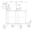
図4は、基板9の主面91上における照射領域および検出領域を示す図である。図4では、2つの光学ヘッド41の照射領域92a,92b(図4中にて平行斜線を付して示す。検出領域93a,93bにおいて同様。)、および、2つの距離検出部5の検出領域93a,93bのみを図示している。図4に示すように、各光学ヘッド41の照射領域92a,92bの中心位置は、当該光学ヘッド41の(−Y)側に設けられる距離検出部5の検出領域93a,93bの中心位置から主走査方向にΔY、副走査方向にΔXだけ離れている。また、照射領域92a,92bの副走査方向の幅もΔXとなっている。以下の説明では、照射領域92a,92bと検出領域93a,93bとの間の主走査方向の中心間距離を「照射−検出間距離」という。   FIG. 4 is a diagram showing an irradiation region and a detection region on the main surface 91 of the substrate 9. In FIG. 4, the irradiation areas 92a and 92b of the two optical heads 41 (shown with parallel oblique lines in FIG. 4; the same applies to the detection areas 93a and 93b) and the detection areas of the two distance detection units 5 Only 93a and 93b are shown. As shown in FIG. 4, the center positions of the irradiation areas 92 a and 92 b of each optical head 41 are mainly determined from the center positions of the detection areas 93 a and 93 b of the distance detection unit 5 provided on the (−Y) side of the optical head 41. They are separated by ΔY in the scanning direction and ΔX in the sub-scanning direction. Further, the width of the irradiation areas 92a and 92b in the sub-scanning direction is also ΔX. In the following description, the center-to-center distance in the main scanning direction between the irradiation regions 92a and 92b and the detection regions 93a and 93b is referred to as “irradiation-detection distance”.

ここで、既述のように、図2のパターン描画装置1では、複数の光学ヘッド41が副走査方向に配列されており、基板9上の描画対象範囲をX方向に幅Wにて等分割した複数の分割領域911a,911b(図4中にて細い実線にて示す。)に対して複数の光学ヘッド41によりそれぞれパターンが描画される。なお、図4では、2つの分割領域911a,911bのみを図示しているが、実際には複数の光学ヘッド41と同数の分割領域に対して、当該複数の光学ヘッド41によりそれぞれパターンが描画される。   Here, as described above, in the pattern drawing apparatus 1 of FIG. 2, the plurality of optical heads 41 are arranged in the sub-scanning direction, and the drawing target range on the substrate 9 is equally divided by the width W in the X direction. Patterns are drawn by the plurality of optical heads 41 on the plurality of divided areas 911a and 911b (indicated by thin solid lines in FIG. 4). In FIG. 4, only the two divided areas 911 a and 911 b are illustrated, but in reality, patterns are drawn by the plurality of optical heads 41 in the same number of divided areas as the plurality of optical heads 41. The

また、照射領域の1回の主走査方向への相対移動(すなわち、主走査)において、各光学ヘッド41により分割領域911a,911b内の線状領域(図4中にて破線の矩形にて示し、符号L1a,L2a等を付している。)にパターンが描画され、線状領域へのパターンの描画が完了する毎に、照射領域の副走査方向への相対移動(すなわち、(−X)方向への副走査)、および、直前の主走査時とは反対の進行方向への照射領域の相対移動を順に行って当該線状領域に隣接する他の線状領域へのパターンの描画が行われる。すなわち、副走査機構23がステージ31を副走査方向に間欠移動しつつ、主走査機構25がステージ31上の基板9を主走査方向に往復移動することにより、往路および復路のそれぞれにおいて主走査方向に伸びる線状領域にパターンが描画される。   Further, in the relative movement of the irradiation area in one main scanning direction (that is, main scanning), linear areas (shown by broken lines in FIG. 4) in the divided areas 911a and 911b by each optical head 41 are shown. Each time the pattern is drawn on the linear area and the pattern is drawn on the linear area, the relative movement in the sub-scanning direction (ie, (−X)) is performed. Sub-scanning in the direction) and the relative movement of the irradiation region in the direction of travel opposite to that in the previous main scanning is sequentially performed, and the pattern is drawn in another linear region adjacent to the linear region. Is called. That is, the main scanning mechanism 25 reciprocates the substrate 9 on the stage 31 in the main scanning direction while the sub scanning mechanism 23 intermittently moves the stage 31 in the sub scanning direction. A pattern is drawn in a linear region extending in a straight line.

実際のパターン描画装置1では、1つの分割領域911a,911b(例えば、X方向の幅Wが92ミリメートル(mm))内に23個の線状領域が隙間なく配列され、各照射領域92a,92b(X方向の幅ΔXが4mmとされる。)の主走査が23回行われることにより、分割領域911a,911bの全体にパターンが描画される(すなわち、基板9の描画範囲の全体にパターンが描画される)。なお、線状領域はストライプとも呼ばれる。   In the actual pattern writing apparatus 1, 23 linear regions are arranged without gaps in one divided region 911a, 911b (for example, the width W in the X direction is 92 millimeters (mm)), and each irradiation region 92a, 92b is arranged. By performing 23 main scans (the width ΔX in the X direction is 4 mm), a pattern is drawn on the entire divided areas 911a and 911b (that is, the pattern is drawn on the entire drawing range of the substrate 9). Drawn). The linear region is also called a stripe.

図4では、照射領域92aに対応する光学ヘッド41によりパターンの描画が行われる23個の線状領域に(+X)側から(−X)方向に向かって符号L1a,L2a,L3a,・・・,L22a,L23aを付し、照射領域92bに対応する光学ヘッド41によりパターンの描画が行われる23個の線状領域に(+X)側から(−X)方向に向かって符号L1b,L2b,L3b,・・・,L22b,L23bを付している。   In FIG. 4, reference signs L1a, L2a, L3a,... From the (+ X) side to the (−X) direction in 23 linear regions in which a pattern is drawn by the optical head 41 corresponding to the irradiation region 92a. , L22a, L23a, and 23 linear regions in which a pattern is drawn by the optical head 41 corresponding to the irradiation region 92b, the signs L1b, L2b, L3b from the (+ X) side toward the (−X) direction. ,..., L22b, L23b are attached.

次に、基板9上にパターンを描画する動作の流れについて図5を参照して説明する。実際には、パターン描画動作の事前処理として、タイミング信号発生部65における各種タイミング信号の発生に係る特定のパラメータの値(後述の駆動遅延距離、並びに、往路パルス入力ON信号および復路パルス入力ON信号の発生位置)を決定する処理が行われる。当該事前処理については後述する。   Next, the flow of operations for drawing a pattern on the substrate 9 will be described with reference to FIG. Actually, as pre-processing of the pattern drawing operation, specific parameter values related to the generation of various timing signals in the timing signal generation unit 65 (drive delay distance described later, forward pulse input ON signal, and backward pulse input ON signal) Is determined). The pre-processing will be described later.

基板9上にパターンを描画する際には、まず、ステージ31上の基板9が所定の描画開始位置に配置される。具体的には、図4に示すように、各光学ヘッド41の照射領域92a,92b、および、各距離検出部5の検出領域93a,93bが分割領域911a,911bの(+Y)側に配置されるとともに、検出領域93a,93bが、X方向に関して各分割領域911a,911b内の最も(+X)側の線状領域L1a,L1bと同じ位置に配置される。そして、基板9の(+Y)方向への移動を開始することにより、検出領域93a,93bが線状領域L1a,L1bに向かって主走査を開始する(ステップS11)。   When drawing a pattern on the substrate 9, first, the substrate 9 on the stage 31 is placed at a predetermined drawing start position. Specifically, as shown in FIG. 4, the irradiation areas 92a and 92b of each optical head 41 and the detection areas 93a and 93b of each distance detector 5 are arranged on the (+ Y) side of the divided areas 911a and 911b. In addition, the detection areas 93a and 93b are arranged at the same positions as the linear areas L1a and L1b on the most (+ X) side in the divided areas 911a and 911b in the X direction. Then, by starting the movement of the substrate 9 in the (+ Y) direction, the detection areas 93a and 93b start main scanning toward the linear areas L1a and L1b (step S11).

図6は、照射領域および検出領域の基板9に対する相対移動を説明するための図であり、図6では、1つの照射領域92および検出領域93(平行斜線を付して示す。)、並びに、照射領域92および検出領域93が通過する一部の線状領域L1〜L3(図6中にて破線の矩形にて示す。)のみを図示している。また、図6では、照射領域92および検出領域93と、線状領域L1〜L3との相対位置の変化を符号A1〜A8を付す複数の段階にて示している。   FIG. 6 is a diagram for explaining the relative movement of the irradiation region and the detection region with respect to the substrate 9. In FIG. 6, one irradiation region 92 and a detection region 93 (shown with parallel oblique lines), and Only a part of the linear regions L1 to L3 (indicated by broken-line rectangles in FIG. 6) through which the irradiation region 92 and the detection region 93 pass are illustrated. Further, in FIG. 6, changes in the relative positions of the irradiation region 92 and the detection region 93 and the linear regions L1 to L3 are shown in a plurality of stages denoted by reference signs A1 to A8.

図6中の段階A1に示すように、検出領域93(の中心)が線状領域L1の(+Y)側の端部に到達すると、検出距離の取得に係る制御(すなわち、距離検出パルス信号の入力、および、当該信号の入力による検出距離の取得に係る処理)が開始される(ステップS12)。実際には、検出領域93が線状領域L1上を通過している間中(図6中の段階A2参照)、検出領域93が主走査方向に一定のピッチ(例えば、4mmのピッチであり、以下、「設定ピッチ」という。)だけ移動する毎に検出距離が取得される。これにより、線状領域L1における基板9のうねり状態が取得される。   As shown in the step A1 in FIG. 6, when the detection area 93 (center) reaches the end on the (+ Y) side of the linear area L1, control related to acquisition of the detection distance (that is, the distance detection pulse signal) Input and processing related to acquisition of the detection distance by inputting the signal) are started (step S12). Actually, while the detection area 93 passes over the linear area L1 (see step A2 in FIG. 6), the detection area 93 has a constant pitch (for example, a pitch of 4 mm) in the main scanning direction. Hereinafter, the detection distance is acquired every time the set pitch is moved. Thereby, the wave | undulation state of the board | substrate 9 in the linear area | region L1 is acquired.

図6中の段階A3のように、検出領域93が線状領域L1の(−Y)側の端部に到達すると、検出距離の取得に係る制御が終了される。そして、主走査方向に関して照射領域92(の中心)が線状領域L1の(−Y)側の端部と同じ位置となる図6中の段階A4を経て、図6中の段階A5に示すように、照射領域92および検出領域93が線状領域L1〜L3よりも(−Y)側の所定位置に到達すると、基板9の主走査方向への移動が停止される(ステップS13)。なお、照射領域92および検出領域93の最初の主走査では、線状領域L1に対する複数の検出距離の取得のみが行われ、光学ヘッド41の制御(フォーカス調整を含む。)は行われない。   When the detection area 93 reaches the end of the linear area L1 on the (−Y) side as in step A3 in FIG. 6, the control for obtaining the detection distance is ended. As shown in step A5 in FIG. 6 after step A4 in FIG. 6 in which the irradiation region 92 (center) is located at the same position as the (−Y) side end of the linear region L1 in the main scanning direction. When the irradiation area 92 and the detection area 93 reach a predetermined position on the (−Y) side of the linear areas L1 to L3, the movement of the substrate 9 in the main scanning direction is stopped (step S13). In the first main scanning of the irradiation area 92 and the detection area 93, only the acquisition of a plurality of detection distances with respect to the linear area L1 is performed, and the control of the optical head 41 (including focus adjustment) is not performed.

制御部6では、次の主走査が行われることが確認されると(ステップS14)、基板9が線状領域の幅(すなわち、照射領域の幅ΔX)だけ(+X)方向に移動する(ステップS15)。これにより、図6中の段階A6に示すように、副走査方向に関して、照射領域92が線状領域L1と同じ位置に配置され、検出領域93が線状領域L1の(−X)側に隣接する線状領域L2と同じ位置に配置される。そして、基板9の(−Y)方向への移動を開始することにより、照射領域92および検出領域93がそれぞれ線状領域L1,L2に向かって主走査を開始する(ステップS11)。   When the controller 6 confirms that the next main scanning is performed (step S14), the substrate 9 moves in the (+ X) direction by the width of the linear region (that is, the width ΔX of the irradiation region) (step S14). S15). Thereby, as shown in step A6 in FIG. 6, with respect to the sub-scanning direction, the irradiation region 92 is arranged at the same position as the linear region L1, and the detection region 93 is adjacent to the (−X) side of the linear region L1. It arrange | positions in the same position as the linear area | region L2 to do. Then, by starting the movement of the substrate 9 in the (−Y) direction, the irradiation region 92 and the detection region 93 start main scanning toward the linear regions L1 and L2, respectively (step S11).

図6中の段階A7に示すように、検出領域93よりも(+Y)側に配置される照射領域92が線状領域L1の(−Y)側の端部に到達すると、光学ヘッド41における光の照射制御が開始される。実際には、照射領域92が線状領域L1の(−Y)側の端部に到達する直前に、フォーカス調整に係る制御(すなわち、駆動開始パルス信号の入力、および、当該信号の入力によるフォーカス調整に係る処理)が開始されており、照射領域92が当該端部に到達した際に、最初のフォーカス調整が完了する。光学ヘッド41におけるフォーカス調整は、直前の主走査時に取得された複数の検出距離に基づいて、照射領域92が主走査方向に設定ピッチだけ移動する毎に行われる。   As shown in step A7 in FIG. 6, when the irradiation region 92 arranged on the (+ Y) side of the detection region 93 reaches the end of the linear region L1 on the (−Y) side, the light in the optical head 41 Irradiation control is started. In practice, immediately before the irradiation region 92 reaches the end of the linear region L1 on the (−Y) side, control related to focus adjustment (that is, input of a drive start pulse signal and focus by input of the signal) When the irradiation area 92 reaches the end portion, the first focus adjustment is completed. The focus adjustment in the optical head 41 is performed each time the irradiation area 92 moves by a set pitch in the main scanning direction based on a plurality of detection distances acquired at the time of the immediately preceding main scanning.

その後、図6中の段階A8に示すように、検出領域93が線状領域L2の(−Y)側の端部に到達すると、検出距離の取得に係る制御が開始され、線状領域L2に対する複数の検出距離が取得される。このようにして、検出距離の取得およびフォーカス調整を行いつつ、線状領域L1にパターンが描画される(ステップS12)。なお、光学ヘッド41における光の照射制御(空間光変調器46の制御)は、設定ピッチよりも十分に短い距離毎に行われる。   Thereafter, as shown in step A8 in FIG. 6, when the detection region 93 reaches the end of the linear region L2 on the (−Y) side, control related to acquisition of the detection distance is started, and the linear region L2 is controlled. A plurality of detection distances are acquired. In this way, a pattern is drawn in the linear region L1 while obtaining the detection distance and adjusting the focus (step S12). Note that light irradiation control (control of the spatial light modulator 46) in the optical head 41 is performed for each distance sufficiently shorter than the set pitch.

照射領域92が線状領域L1の(+Y)側の端部に到達すると、照射制御およびフォーカス調整に係る制御が終了され、検出領域93が線状領域L2の(+Y)側の端部に到達すると、検出距離の取得に係る制御が終了される。照射領域92および検出領域93は、(+Y)方向にさらに相対移動し、線状領域L1〜L3よりも(+Y)側の所定位置に到達すると、基板9の主走査方向への移動が停止される(ステップS13)。   When the irradiation region 92 reaches the (+ Y) side end of the linear region L1, the control related to the irradiation control and focus adjustment is finished, and the detection region 93 reaches the (+ Y) side end of the linear region L2. Then, the control related to acquisition of the detection distance is terminated. The irradiation area 92 and the detection area 93 are further moved relative to each other in the (+ Y) direction. When the irradiation area 92 and the detection area 93 reach a predetermined position on the (+ Y) side of the linear areas L1 to L3, the movement of the substrate 9 in the main scanning direction is stopped. (Step S13).

次の主走査が行われることが確認されると(ステップS14)、基板9が線状領域の幅だけ(+X)方向に移動し(ステップS15)、副走査方向に関して、照射領域92が線状領域L2と同じ位置に配置され、検出領域93が線状領域L2の(−X)側に隣接する線状領域L3と同じ位置に配置される。そして、基板9の(+Y)方向への移動が開始され(ステップS11)、線状領域L3に対する複数の検出距離の取得、および、直前の主走査時に線状領域L2に対して取得された複数の検出距離に基づく複数回のフォーカス調整を行いつつ、線状領域L2にパターンが描画される(ステップS12)。照射領域92および検出領域93が、線状領域L1〜L3よりも(−Y)側に到達すると、基板9の主走査方向への移動が停止される(ステップS13)。   When it is confirmed that the next main scanning is performed (step S14), the substrate 9 is moved in the (+ X) direction by the width of the linear region (step S15), and the irradiation region 92 is linear in the sub-scanning direction. The detection area 93 is arranged at the same position as the area L2, and the detection area 93 is arranged at the same position as the linear area L3 adjacent to the (−X) side of the linear area L2. Then, the movement of the substrate 9 in the (+ Y) direction is started (step S11), and a plurality of detection distances with respect to the linear region L3 are acquired, and a plurality of acquired with respect to the linear region L2 during the immediately preceding main scanning. A pattern is drawn in the linear region L2 while performing a plurality of focus adjustments based on the detected distance (step S12). When the irradiation region 92 and the detection region 93 reach the (−Y) side from the linear regions L1 to L3, the movement of the substrate 9 in the main scanning direction is stopped (step S13).

以上のように、パターン描画装置1では、上記ステップS15,S11〜S13の処理が繰り返されることにより(ステップS14)、一の主走査による線状領域へのパターンの描画が完了する毎に、ステージ31の副走査方向への移動、および、直前の主走査時とは反対の進行方向へのステージ31の移動を順に行って当該線状領域に平行な他の線状領域へのパターンの描画が行われるとともに、各主走査時に、複数の検出距離の取得、および、直前の主走査時に取得された複数の検出距離に基づく複数回のフォーカス調整が行われる。そして、全ての線状領域へのパターンの描画が完了すると、パターン描画装置1におけるパターンの描画動作が完了する。   As described above, the pattern drawing apparatus 1 repeats the processes of steps S15 and S11 to S13 (step S14), so that each time drawing of a pattern on a linear region by one main scan is completed, The movement of the stage 31 in the sub-scanning direction and the movement of the stage 31 in the direction of travel opposite to that in the previous main scanning are sequentially performed to draw a pattern in another linear area parallel to the linear area. In addition, at each main scan, a plurality of detection distances are acquired, and a plurality of focus adjustments are performed based on the plurality of detection distances acquired at the immediately preceding main scan. When the pattern drawing on all the linear regions is completed, the pattern drawing operation in the pattern drawing apparatus 1 is completed.

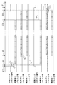
ここで、各主走査時に、複数の検出距離の取得および複数回のフォーカス調整を行う際の制御部6によるタイミング制御について説明する。図7は、制御部6によるタイミング制御を説明するための図である。図7中の最上段はY方向の位置を示し、上から2段目(Y軸の下側)は、往路におけるパルス入力ON信号(以下、「往路パルス入力ON信号」ともいう。)を示し、上から3段目は往路における距離検出パルス信号を示す。図7中の上から4段目は往路における駆動開始パルス信号を示し、上から5段目は往路における駆動完了パルス信号を示している。また、図7中の上から6段目は、復路におけるパルス入力ON信号(以下、「復路パルス入力ON信号」ともいう。)を示し、上から7段目は復路における距離検出パルス信号を示す。図7中の上から8段目は復路における駆動開始パルス信号を示し、最下段は復路における駆動完了パルス信号を示している。上記の駆動完了パルス信号は、対物レンズ472の目標位置への移動の完了を示す信号であり、図3のAF制御部64により生成される。   Here, timing control by the control unit 6 when acquiring a plurality of detection distances and performing a plurality of focus adjustments in each main scan will be described. FIG. 7 is a diagram for explaining timing control by the control unit 6. 7 indicates the position in the Y direction, and the second level from the top (below the Y axis) indicates the pulse input ON signal in the forward path (hereinafter also referred to as “forward pulse input ON signal”). The third row from the top shows the distance detection pulse signal in the forward path. In FIG. 7, the fourth row from the top indicates the drive start pulse signal in the forward path, and the fifth row from the top indicates the drive completion pulse signal in the forward path. Further, the sixth stage from the top in FIG. 7 shows a pulse input ON signal in the return path (hereinafter also referred to as “return pulse input ON signal”), and the seventh stage from the top shows a distance detection pulse signal in the return path. . The eighth stage from the top in FIG. 7 shows the drive start pulse signal in the return path, and the bottom stage shows the drive completion pulse signal in the return path. The drive completion pulse signal is a signal indicating completion of movement of the objective lens 472 to the target position, and is generated by the AF control unit 64 in FIG.

検出領域93が照射領域92よりも先行する往路では、ステージ31が(+Y)方向に移動して、ステージ31の所定部分が図7中の最上段にて符号α1を付す主走査方向の位置へと到達すると、タイミング信号発生部65(図3参照)において、図7中の上から2段目に示すように、往路パルス入力ON信号が発生する(立ち上がる)。続いて、往路パルス入力ON信号の発生位置から設定ピッチT1(設定ピッチT1以外の距離であってもよい。)だけステージ31が移動すると、図7中の上から3段目に示すように、最初の距離検出パルス信号が発生し、検出距離が取得される。このとき、ステージ31は図7中の最上段にて符号α2を付す位置に到達し、図6の段階A1に示すように、検出領域93が線状領域の(+Y)側の端部上に位置する。その後、基板9が設定ピッチT1だけ移動する毎に距離検出パルス信号がAF制御部64に繰り返し入力され、検出距離が取得される。このように、タイミング信号発生部65では、往路パルス入力ON信号の発生をトリガとして位置測定部26の出力に基づいて一定の設定ピッチT1にて距離検出パルス信号が繰り返し発生される。   In the forward path where the detection area 93 precedes the irradiation area 92, the stage 31 moves in the (+ Y) direction, and a predetermined portion of the stage 31 moves to a position in the main scanning direction denoted by reference numeral α1 at the uppermost stage in FIG. In the timing signal generator 65 (see FIG. 3), the forward pulse input ON signal is generated (rises) as shown in the second stage from the top in FIG. Subsequently, when the stage 31 moves by a set pitch T1 (may be a distance other than the set pitch T1) from the generation position of the forward pulse input ON signal, as shown in the third stage from the top in FIG. The first distance detection pulse signal is generated and the detection distance is acquired. At this time, the stage 31 reaches the position denoted by reference numeral α2 in the uppermost stage in FIG. 7, and the detection area 93 is positioned on the (+ Y) side end of the linear area as shown in the stage A1 in FIG. To position. Thereafter, each time the substrate 9 moves by the set pitch T1, the distance detection pulse signal is repeatedly input to the AF control unit 64, and the detection distance is acquired. As described above, the timing signal generation unit 65 repeatedly generates the distance detection pulse signal at a constant set pitch T1 based on the output of the position measurement unit 26 using the generation of the forward pulse input ON signal as a trigger.

ここで、パターン描画装置1では、後述する事前処理において、フォーカス機構471への駆動開始パルス信号の入力から、当該入力に対応するフォーカス調整の完了(すなわち、対物レンズ472の目標位置への移動の完了)までの時間に相当するステージ31の移動距離(すなわち、照射領域92および検出領域93の基板9に対する相対的な移動距離)が駆動遅延距離T2として設定されている。   Here, in the pattern drawing apparatus 1, in the pre-processing described later, from the input of the drive start pulse signal to the focus mechanism 471, the focus adjustment corresponding to the input is completed (that is, the movement of the objective lens 472 to the target position). The movement distance of the stage 31 corresponding to the time until completion) (that is, the relative movement distance of the irradiation region 92 and the detection region 93 with respect to the substrate 9) is set as the drive delay distance T2.

タイミング信号発生部65では、図7中の上から3段目および4段目に示すように、照射領域92と検出領域93との間の主走査方向の照射−検出間距離T3から駆動遅延距離T2を減じた距離だけ、各距離検出パルス信号の発生位置から進行方向前側((+Y)側)の位置にステージ31が移動した際に、駆動開始パルス信号が発生される。図3のAF制御部64では、駆動開始パルス信号の入力により対物レンズ472の目標位置が求められるとともに、対物レンズ472を当該目標位置へと移動するための指令値がアクチュエータ473に出力され、対物レンズ472の移動が行われる。そして、図7中の上から3段目および5段目に示すように、各距離検出パルス信号の発生位置から基板9が(+Y)側に照射−検出間距離T3だけ移動した際に(または、駆動開始パルス信号の発生位置から駆動遅延距離T2だけ移動した際に)、対物レンズ472の目標位置への移動(すなわち、フォーカス調整)が完了する。   In the timing signal generator 65, as shown in the third and fourth stages from the top in FIG. 7, the driving delay distance is determined from the irradiation-detection distance T3 in the main scanning direction between the irradiation area 92 and the detection area 93. A drive start pulse signal is generated when the stage 31 moves from the position where each distance detection pulse signal is generated to the position on the front side in the traveling direction ((+ Y) side) by the distance obtained by subtracting T2. In the AF control unit 64 of FIG. 3, the target position of the objective lens 472 is obtained by inputting the drive start pulse signal, and a command value for moving the objective lens 472 to the target position is output to the actuator 473, The lens 472 is moved. Then, as shown in the third and fifth stages from the top in FIG. 7, when the substrate 9 moves from the generation position of each distance detection pulse signal to the (+ Y) side by the irradiation-detection distance T3 (or When the driving start pulse signal is moved by the driving delay distance T2), the movement of the objective lens 472 to the target position (that is, focus adjustment) is completed.

既述のように、往路では、検出領域93が照射領域92よりも先行しており、主面91上において照射領域92と検出領域93とは主走査方向に照射−検出間距離T3だけ離れているため、主走査方向のみに着目した場合に、各距離検出パルス信号の発生時における基板9上の検出領域93の位置(すなわち、検出距離が取得される基板9上の位置であり、以下、「検出位置」という。)と、当該距離検出パルス信号に対応する駆動開始パルス信号によるフォーカス調整が完了する際の基板9上の照射領域92の位置とが一致することとなる。なお、図7中の最上段では、往路における最初の駆動開始パルス信号によるフォーカス調整が完了する際のステージ31の位置を符号α3を付す矢印にて示している。   As described above, in the forward path, the detection area 93 precedes the irradiation area 92, and the irradiation area 92 and the detection area 93 on the main surface 91 are separated by an irradiation-detection distance T3 in the main scanning direction. Therefore, when focusing on only the main scanning direction, the position of the detection region 93 on the substrate 9 when each distance detection pulse signal is generated (that is, the position on the substrate 9 from which the detection distance is acquired, And the position of the irradiation region 92 on the substrate 9 when the focus adjustment by the drive start pulse signal corresponding to the distance detection pulse signal is completed. In the uppermost stage in FIG. 7, the position of the stage 31 when the focus adjustment by the first drive start pulse signal in the forward path is completed is indicated by an arrow with the symbol α3.

一方で、照射領域92が検出領域93よりも先行する復路では、ステージ31が(−Y)方向に移動して、図7中の最上段にて符号β1を付す主走査方向の位置へと到達すると、タイミング信号発生部65において、図7中の上から6段目(下から4段目)に示すように、復路パルス入力ON信号が発生する(立ち上がる)。続いて、復路パルス入力ON信号の発生位置から設定ピッチT1だけ基板9が移動すると、図7中の上から8段目(下から2段目)に示すように、最初の駆動開始パルス信号が発生し、その後、基板9が設定ピッチT1だけ移動する毎に駆動開始パルス信号がAF制御部64に繰り返し入力される。このように、タイミング信号発生部65では、復路パルス入力ON信号の発生をトリガとして位置測定部26の出力に基づいて一定の設定ピッチT1にて駆動開始パルス信号が繰り返し発生される。   On the other hand, on the return path in which the irradiation area 92 precedes the detection area 93, the stage 31 moves in the (−Y) direction and reaches the position in the main scanning direction denoted by the reference symbol β1 at the uppermost stage in FIG. Then, in the timing signal generator 65, as shown in the sixth stage from the top (fourth stage from the bottom) in FIG. 7, the return pulse input ON signal is generated (rises). Subsequently, when the substrate 9 moves from the position where the return pulse input ON signal is generated by the set pitch T1, the first drive start pulse signal is displayed as shown in the eighth stage from the top (second stage from the bottom) in FIG. After that, a drive start pulse signal is repeatedly input to the AF control unit 64 every time the substrate 9 moves by the set pitch T1. Thus, the timing signal generator 65 repeatedly generates a drive start pulse signal at a constant set pitch T1 based on the output of the position measuring unit 26, triggered by the generation of the return pulse input ON signal.

そして、図7中の最下段に示すように、各駆動開始パルス信号の発生位置から基板9が(−Y)側に駆動遅延距離T2だけ移動した際に、当該駆動開始パルス信号に対応する対物レンズ472の目標位置への移動が(原則として)完了する。例えば、復路における最初の駆動開始パルス信号によるフォーカス調整が完了する際の照射領域92の位置は、図6の段階A7に示すように線状領域の(−Y)側の端部となり、このときのステージ31の位置を図7中の最上段にて符号β2を付す矢印にて示している。   Then, as shown in the lowermost stage in FIG. 7, when the substrate 9 moves to the (−Y) side from the generation position of each drive start pulse signal by the drive delay distance T2, the objective corresponding to the drive start pulse signal is displayed. The movement of the lens 472 to the target position is completed (in principle). For example, the position of the irradiation region 92 when the focus adjustment by the first drive start pulse signal in the return path is completed is the end on the (−Y) side of the linear region as shown in step A7 in FIG. The position of the stage 31 is indicated by an arrow with a symbol β2 at the uppermost stage in FIG.

また、タイミング信号発生部65では、図7中の上から7段目および8段目(下から2段目および3段目)に示すように、照射−検出間距離T3に駆動遅延距離T2を加えた距離だけ、各駆動開始パルス信号の発生位置から進行方向前側((−Y)側)の位置に基板9が移動した際に、距離検出パルス信号が発生する。したがって、照射領域92が検出領域93よりも照射−検出間距離T3だけ先行する復路においても、主走査方向のみに着目した場合に、各駆動開始パルス信号によるフォーカス調整が完了する際の基板9上の照射領域92の位置と、当該駆動開始パルス信号に対応する距離検出パルス信号の発生時における基板9上の検出領域93の位置(検出位置)とが一致することとなる。なお、図7中の最上段では、復路における最初の距離検出パルス信号の発生時におけるステージ31の位置を符号β3を付す矢印にて示している。   Further, in the timing signal generator 65, as shown in the seventh and eighth stages from the top in FIG. 7 (second and third stages from the bottom), the drive delay distance T2 is set to the irradiation-detection distance T3. A distance detection pulse signal is generated when the substrate 9 is moved from the generation position of each drive start pulse signal to the front side in the traveling direction ((−Y) side) by the added distance. Therefore, on the return path where the irradiation region 92 precedes the detection region 93 by the irradiation-detection distance T3, when focusing only on the main scanning direction, the focus adjustment by each drive start pulse signal is completed on the substrate 9. The position of the irradiation region 92 coincides with the position (detection position) of the detection region 93 on the substrate 9 when the distance detection pulse signal corresponding to the drive start pulse signal is generated. In the uppermost stage in FIG. 7, the position of the stage 31 when the first distance detection pulse signal is generated in the return path is indicated by an arrow with a symbol β3.

パターン描画装置1では、主走査方向に関して、往路における複数の検出距離の基板9上の検出位置(複数の検出位置)と、復路における複数の検出距離の検出位置とが近似するように、後述する事前処理において、往路におけるパルス信号入力の能動化を示す往路パルス入力ON信号、および、復路におけるパルス信号入力の能動化を示す復路パルス入力ON信号の双方の主走査方向における発生位置が設定されている。これにより、往路および復路のそれぞれにて線状領域にパターンを描画する際に、直前の主走査にて当該線状領域に対して取得された各検出距離の検出位置にて、当該検出距離を用いたフォーカス調整を行うことが可能となる。このように、パターン描画装置1では、駆動遅延距離T2、並びに、往路および復路におけるパルス入力ON信号の発生位置の設定のみで、各主走査において、取得済みの検出距離の検出位置にて当該検出距離を用いたフォーカス調整が可能となる。なお、設定ピッチT1は操作者により任意に定められるものであり、照射−検出間距離T3はパターン描画装置1の設計により予め決められるものである。   In the pattern drawing apparatus 1, the detection positions (a plurality of detection positions) on the substrate 9 at a plurality of detection distances in the forward path and the detection positions at a plurality of detection distances in the return path are approximated with respect to the main scanning direction. In the pre-processing, the generation positions in the main scanning direction of both the forward pulse input ON signal indicating activation of the pulse signal input in the forward path and the backward pulse input ON signal indicating activation of the pulse signal input in the return path are set. Yes. Thus, when the pattern is drawn in the linear area in each of the forward path and the backward path, the detection distance is set at the detection position of each detection distance acquired for the linear area in the immediately preceding main scan. The used focus adjustment can be performed. As described above, in the pattern drawing apparatus 1, only the setting of the drive delay distance T2 and the generation position of the pulse input ON signal in the forward path and the backward path is performed at the detection position of the acquired detection distance in each main scan. Focus adjustment using distance is possible. The set pitch T1 is arbitrarily determined by the operator, and the irradiation-detection distance T3 is determined in advance by the design of the pattern drawing apparatus 1.

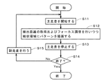
次に、パターン描画動作の事前処理として、駆動遅延距離、並びに、往路および復路におけるパルス入力ON信号の発生位置を決定する処理について、図8を参照して説明する。図8のステップS21の処理は、主としてパターン描画装置1の組立時や使用現場への設置時に行われるものであり、図8のステップS22〜S25の処理は、ステップS21の処理が行われる場合の他、主走査機構25におけるステージ31の移動速度を変更する場合にも行われるものである。なお、図8の処理がパターン描画装置1の使用における定期的なキャリブレーション等として行われてもよい。   Next, a process for determining the driving delay distance and the generation position of the pulse input ON signal in the forward path and the backward path as the pre-process of the pattern drawing operation will be described with reference to FIG. The process in step S21 in FIG. 8 is mainly performed when the pattern drawing apparatus 1 is assembled or installed in the use site. The processes in steps S22 to S25 in FIG. 8 are performed when the process in step S21 is performed. In addition, it is also performed when the moving speed of the stage 31 in the main scanning mechanism 25 is changed. Note that the process of FIG. 8 may be performed as periodic calibration or the like when the pattern drawing apparatus 1 is used.

パターン描画動作の事前処理では、まず、駆動遅延距離が求められる(ステップS21)。具体的には、パターン描画装置1において、対物レンズ472の変位を測定する変位計(例えば、レーザー変位計)を一時的に設け、フォーカス機構471に駆動開始パルス信号を入力した後、任意に決定された対物レンズ472の目標位置への移動が完了するまでの時間が測定される。上記測定は、対物レンズ472の移動前の位置と目標位置との様々な組合せ(ただし、通常、基板9のうねりは緩やかであるため、移動前の位置と目標位置との差は比較的小さくされる。)に対して行われ、測定された時間の平均値等の代表値が駆動遅延時間として求められる。そして、パターン描画動作におけるステージ31の主走査方向への移動速度に駆動遅延時間を乗じることにより、フォーカス機構471への駆動開始パルス信号の入力からフォーカス調整の完了までの駆動遅延時間に相当するステージ31の移動距離が駆動遅延距離T2として決定される。既述のように、ステップS21の処理は、パターン描画装置1の組立時や使用現場への設置時に主として行われる。   In the pre-processing of the pattern drawing operation, first, a drive delay distance is obtained (step S21). Specifically, in the pattern writing apparatus 1, a displacement meter (for example, a laser displacement meter) that measures the displacement of the objective lens 472 is temporarily provided, and a drive start pulse signal is input to the focus mechanism 471 and then arbitrarily determined. The time until the movement of the objective lens 472 to the target position is completed is measured. In the above measurement, various combinations of the position before the movement of the objective lens 472 and the target position (however, since the undulation of the substrate 9 is generally gentle, the difference between the position before the movement and the target position is made relatively small. The representative value such as the average value of the measured time is obtained as the drive delay time. A stage corresponding to the drive delay time from the input of the drive start pulse signal to the focus mechanism 471 until the completion of the focus adjustment is obtained by multiplying the moving speed of the stage 31 in the main scanning direction in the pattern drawing operation by the drive delay time. The moving distance of 31 is determined as the drive delay distance T2. As described above, the process of step S21 is mainly performed when the pattern drawing apparatus 1 is assembled or installed at the site of use.

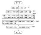
駆動遅延距離が決定されると、操作者により復路パルス入力ON信号の発生位置が任意に決定される。そして、ステージ31が復路の開始位置へと配置された後、(−Y)方向への移動が開始され、ステージ31が当該発生位置へと到達した際に、タイミング信号発生部65にて復路パルス入力ON信号が発生する。図7中の上から6ないし9段目(下から1ないし4段目)を参照して説明したように、復路パルス入力ON信号の発生後、ステージ31が設定ピッチT1(予め定められている。)だけ移動する毎に駆動開始パルス信号が発生する。また、照射−検出間距離T3に駆動遅延距離T2を加えた距離だけ、各駆動開始パルス信号の発生位置から進行方向前側((−Y)側)の位置にステージ31が移動した際に、距離検出パルス信号が発生する。これにより、復路に関して任意のパルス入力ON信号の発生位置にて一の線状領域(以下、「特定線状領域」という。)に対する複数の検出距離が取得される(ステップS22)。   When the driving delay distance is determined, the position where the return pulse input ON signal is generated is arbitrarily determined by the operator. Then, after the stage 31 is placed at the start position of the return path, the movement in the (−Y) direction is started, and when the stage 31 reaches the generation position, the timing signal generation unit 65 returns the return path pulse. An input ON signal is generated. As described with reference to the 6th to 9th stages from the top (1st to 4th stages from the bottom) in FIG. 7, after the return pulse input ON signal is generated, the stage 31 is set to the set pitch T1 (predetermined). A drive start pulse signal is generated every time movement is performed. Further, when the stage 31 is moved from the generation position of each drive start pulse signal to the front side in the traveling direction ((−Y) side) by the distance obtained by adding the drive delay distance T2 to the irradiation-detection distance T3, the distance A detection pulse signal is generated. As a result, a plurality of detection distances with respect to one linear region (hereinafter referred to as “specific linear region”) are acquired at a position where an arbitrary pulse input ON signal is generated on the return path (step S22).

続いて、復路における複数の検出距離を取得した際の複数の距離検出パルス信号の発生位置のうち最も(−Y)側の発生位置から設定ピッチT1だけ(−Y)方向に離れた位置が基準位置として決定される。そして、設定ピッチT1よりも小さい予め設定された距離(例えば、設定ピッチT1の1/30以上1/3以下の距離)の1、2、3、・・・、M(ただし、Mは任意の正の整数)倍だけ、基準位置から(+Y)方向および(−Y)方向のそれぞれに離れた位置、および、基準位置が往路パルス入力ON信号の発生位置の複数の候補として決定される。なお、発生位置の複数の候補の間隔は、設定ピッチT1よりも小さい幅であるならば、必ずしも一定でなくてもよい。   Subsequently, a position that is separated in the (−Y) direction by the set pitch T1 from the most (−Y) side generation position among the generation positions of the plurality of distance detection pulse signals when acquiring a plurality of detection distances on the return path is a reference. Determined as position. 1, 2, 3,..., M (where M is an arbitrary distance) that is smaller than the set pitch T1 (for example, a distance of 1/30 to 1/3 of the set pitch T1). Positions separated by (positive integer) times in the (+ Y) direction and (−Y) direction from the reference position, and the reference position are determined as a plurality of candidates for the forward pulse input ON signal generation position. It should be noted that the intervals between the plurality of candidates for the generation position are not necessarily constant as long as the width is smaller than the set pitch T1.

制御部6では、往路パルス入力ON信号の発生位置の複数の候補のうちの1つが選択される。そして、ステップS22の処理にて複数の検出距離が取得された線状領域(すなわち、特定線状領域)の(+Y)側に検出領域93が配置された後、ステージ31の(+Y)方向への移動が開始され、ステージ31が選択された発生位置へと到達した際に、タイミング信号発生部65にて往路パルス入力ON信号が発生する。図7中の上から2ないし5段目を参照して説明したように、往路パルス入力ON信号の発生後、ステージ31が設定ピッチT1だけ移動する毎に距離検出パルス信号が発生する。これにより、往路パルス入力ON信号の選択された発生位置に基づく複数の検出距離が取得される。パターン描画装置1では、往路パルス入力ON信号の発生位置の複数の候補のそれぞれに対して上記動作が行われる。このようにして、往路パルス入力ON信号の発生位置を設定ピッチT1よりも小さい間隔にて複数通りに変更して、往路パルス入力ON信号の各発生位置に関して、同一の特定線状領域に対する複数の検出距離が取得される(ステップS23)。   The control unit 6 selects one of a plurality of candidates for the generation position of the forward pulse input ON signal. Then, after the detection region 93 is arranged on the (+ Y) side of the linear region (that is, the specific linear region) from which a plurality of detection distances have been acquired in the process of step S22, the detection region 93 is moved in the (+ Y) direction of the stage 31. When the stage 31 reaches the selected generation position, the timing signal generator 65 generates a forward pulse input ON signal. As described with reference to the second to fifth stages from the top in FIG. 7, after the forward pulse input ON signal is generated, the distance detection pulse signal is generated every time the stage 31 moves by the set pitch T1. Thereby, a plurality of detection distances based on the selected generation position of the forward pulse input ON signal are acquired. In the pattern drawing apparatus 1, the above operation is performed for each of a plurality of candidates for the generation position of the forward pulse input ON signal. In this way, the generation position of the forward pulse input ON signal is changed in a plurality of ways at intervals smaller than the set pitch T1, and a plurality of generation positions of the forward pulse input ON signal with respect to the same specific linear region is generated. A detection distance is acquired (step S23).

制御部6では、往路パルス入力ON信号の各発生位置に関する複数の検出距離と、ステップS22の処理にて取得された復路における複数の検出距離との差の絶対値の和(差の二乗和等であってもよい。)が求められる。詳細には、往路および復路のそれぞれにおける複数の検出距離の個数がK(Kは1よりも大きい正の整数)である場合に、往路における複数の検出距離うちL(Lは1以上K以下の正の整数)番目の距離検出パルス信号にて取得された検出距離と、復路における複数の検出距離のうち((K+1)−L)番目に取得された検出距離との差の絶対値が求められ、これらの値の和が評価値として取得される。そして、往路パルス入力ON信号の複数の発生位置(複数の候補)と、当該複数の発生位置に対する複数の評価値とを変数とする2次の近似式が求められ、評価値が最小となる発生位置が当該近似式に基づいて特定される。当該発生位置は、実際のパターン描画動作での往路におけるパルス入力ON信号の発生位置として決定される(ステップS24)。   In the control unit 6, the sum of the absolute values (the sum of squares of the difference, etc.) of the difference between the plurality of detection distances related to each generation position of the forward pulse input ON signal and the plurality of detection distances in the return path acquired in the process of step S22. May also be required). Specifically, when the number of the plurality of detection distances in each of the forward path and the return path is K (K is a positive integer larger than 1), L (L is 1 or more and K or less) among the plurality of detection distances in the forward path. The absolute value of the difference between the detection distance acquired by the (positive integer) th distance detection pulse signal and the detection distance acquired at the ((K + 1) -L) th among the plurality of detection distances in the return path is obtained. The sum of these values is acquired as the evaluation value. Then, a quadratic approximate expression having a plurality of generation positions (a plurality of candidates) of the forward pulse input ON signal and a plurality of evaluation values for the plurality of generation positions as variables is obtained, and the generation that minimizes the evaluation value is generated. The position is specified based on the approximate expression. The generation position is determined as the generation position of the pulse input ON signal in the forward path in the actual pattern drawing operation (step S24).

評価値が最小となる往路パルス入力ON信号の発生位置は、当該発生位置に関して特定線状領域に対して取得される複数の検出距離と、ステップS22の処理にて取得された復路における複数の検出距離とが最も近似すると考えられるものであるため、当該発生位置にて往路パルス入力ON信号を発生させた際における複数の検出距離の検出位置と、ステップS22の処理の際における復路パルス入力ON信号での複数の検出距離の検出位置とが近似(一致を含む。)することとなる。なお、距離検出パルス信号の発生から、ラインセンサ54(図3参照)からの受光出力データが実際にラッチされるまでの遅れ時間の影響等、往路および復路における各種動作タイミングのずれにより、通常、ステップS24にて決定される往路パルス入力ON信号の発生位置は、上記基準位置からずれたものとなる。   The generation position of the forward pulse input ON signal that minimizes the evaluation value is a plurality of detection distances acquired for the specific linear region with respect to the generation position and a plurality of detections in the return path acquired in the process of step S22. Since the distance is considered to be the most approximate, the detection positions of a plurality of detection distances when the forward pulse input ON signal is generated at the generation position and the return pulse input ON signal at the time of the process of step S22 The detection positions of a plurality of detection distances at Approximate (including coincidence). Note that, due to a shift in various operation timings in the forward path and the return path, such as the influence of the delay time from the generation of the distance detection pulse signal until the light reception output data from the line sensor 54 (see FIG. 3) is actually latched, The generation position of the forward pulse input ON signal determined in step S24 is shifted from the reference position.

以上のようにして、駆動遅延距離T2、並びに、往路パルス入力ON信号、および、復路パルス入力ON信号の主走査方向における発生位置(すなわち、各種タイミング信号の発生に係る特定のパラメータの値)が決定されると、これらのパラメータの値はタイミング信号発生部65に設定され、パターン描画動作の事前処理が完了する(ステップS25)。実際のパターン描画動作では、これらのパラメータの値に基づいてタイミング信号発生部65から各種タイミング信号が出力されることにより、各主走査にて線状領域にパターンを描画する際に、直前の主走査にて当該線状領域に対して取得された各検出距離の検出位置にて、当該検出距離を用いたフォーカス調整を行うことが可能となる。なお、実際の基板9上の描画対象範囲に合わせて、往路および復路におけるパルス入力ON信号の発生位置が同じ距離だけ主走査方向にシフトされてもよい。   As described above, the driving delay distance T2, the generation position of the forward pulse input ON signal, and the backward pulse input ON signal in the main scanning direction (that is, the value of a specific parameter related to the generation of various timing signals) are determined. When determined, the values of these parameters are set in the timing signal generator 65, and the preliminary processing of the pattern drawing operation is completed (step S25). In the actual pattern drawing operation, various timing signals are output from the timing signal generator 65 based on the values of these parameters, so that when the pattern is drawn in the linear region in each main scan, the immediately preceding main pattern is output. Focus adjustment using the detection distance can be performed at the detection position of each detection distance acquired for the linear region by scanning. The generation position of the pulse input ON signal in the forward path and the backward path may be shifted in the main scanning direction by the same distance in accordance with the drawing target range on the actual substrate 9.

ところで、仮に、駆動遅延距離T2を考慮せず、往路において各距離検出パルス信号の発生位置から照射−検出間距離T3だけ進行方向前側の位置にて駆動開始パルス信号を発生させた場合、各距離検出パルス信号に対応する駆動開始パルス信号によるフォーカス調整が完了する際の照射領域92の位置が、当該距離検出パルス信号の発生時における検出領域93の位置から(+Y)側に駆動遅延距離T2だけずれてしまう。また、復路において各駆動開始パルス信号の発生位置から照射−検出間距離T3だけ進行方向前側の位置にて距離検出パルス信号を発生させた場合、各駆動開始パルス信号によるフォーカス調整が完了する際の照射領域92の位置が、当該駆動開始パルス信号に対応する距離検出パルス信号の発生時における検出領域93の位置から(−Y)側に駆動遅延距離T2だけずれてしまう。   By the way, if the drive start pulse signal is generated at a position in the forward direction of the irradiation-detection distance T3 from the generation position of each distance detection pulse signal in the forward path without considering the drive delay distance T2, The position of the irradiation region 92 when the focus adjustment by the drive start pulse signal corresponding to the detection pulse signal is completed is the drive delay distance T2 on the (+ Y) side from the position of the detection region 93 when the distance detection pulse signal is generated. It will shift. Further, when the distance detection pulse signal is generated at the position in front of the traveling direction by the irradiation-detection distance T3 from the generation position of each drive start pulse signal in the return path, the focus adjustment by each drive start pulse signal is completed. The position of the irradiation region 92 is shifted from the position of the detection region 93 when the distance detection pulse signal corresponding to the drive start pulse signal is generated to the (−Y) side by the drive delay distance T2.

これに対し、パターン描画装置1では、検出領域93が照射領域92よりも先行する往路において、往路パルス入力ON信号の発生をトリガとして、設定ピッチT1にて距離検出パルス信号を繰り返し発生し、照射−検出間距離T3から駆動遅延距離T2を減じた距離だけ各距離検出パルス信号の発生位置から進行方向前側の位置にて駆動開始パルス信号を発生することにより、主走査方向に関して各距離検出パルス信号の発生時における検出領域93の位置と、当該距離検出パルス信号に対応する駆動開始パルス信号によるフォーカス調整が完了する際の照射領域92の位置とを一致させることができる。また、照射領域92が検出領域93よりも先行する復路において、復路パルス入力ON信号の発生をトリガとして、設定ピッチT1にて駆動開始パルス信号を繰り返し発生し、照射−検出間距離T3に駆動遅延距離T2を加えた距離だけ各駆動開始パルス信号の発生位置から進行方向前側の位置にて距離検出パルス信号を発生することにより、主走査方向に関して各駆動開始パルス信号によるフォーカス調整が完了する際の照射領域92の位置と、当該駆動開始パルス信号に対応する距離検出パルス信号の発生時における検出領域93の位置とを一致させることができる。   On the other hand, in the pattern drawing apparatus 1, in the forward path in which the detection area 93 precedes the irradiation area 92, the generation of the forward pulse input ON signal is used as a trigger to repeatedly generate the distance detection pulse signal at the set pitch T1. -By generating a drive start pulse signal at a position in front of the traveling direction from the generation position of each distance detection pulse signal by a distance obtained by subtracting the drive delay distance T2 from the detection distance T3, each distance detection pulse signal in the main scanning direction The position of the detection region 93 at the time of the occurrence of this can coincide with the position of the irradiation region 92 when the focus adjustment by the drive start pulse signal corresponding to the distance detection pulse signal is completed. Further, in the return path in which the irradiation area 92 precedes the detection area 93, the generation of the return pulse input ON signal is used as a trigger to repeatedly generate the drive start pulse signal at the set pitch T1, and the drive delay is set to the irradiation-detection distance T3. When the distance detection pulse signal is generated at a position in front of the traveling direction from the generation position of each drive start pulse signal by the distance including the distance T2, the focus adjustment by each drive start pulse signal in the main scanning direction is completed. The position of the irradiation region 92 can be matched with the position of the detection region 93 when the distance detection pulse signal corresponding to the drive start pulse signal is generated.

また、パターン描画装置1では、主走査方向に関して往路における複数の検出距離の検出位置と、復路における複数の検出距離の検出位置とが近似するように、往路および復路におけるパルス入力ON信号の主走査方向の発生位置が制御部6に設定される。これにより、各主走査において、直前の主走査にて取得される複数の検出距離を用いて複数回のフォーカス調整が行われる際に、光学ヘッド41からの光ビームの合焦位置を基板9のうねりに従って主面91上に精度よく合わせることが実現される。その結果、パターン描画装置1では、往路および復路の双方にて高精度なパターン描画を行って、基板9上に高精細なパターンを精度よく、かつ、短時間にて描画することが可能となる。   In the pattern drawing apparatus 1, the main scanning of the pulse input ON signal in the forward path and the backward path is such that the detection positions of the plurality of detection distances in the forward path and the detection positions of the plurality of detection distances in the backward path are approximated in the main scanning direction. The direction generation position is set in the control unit 6. Thereby, in each main scan, when the focus adjustment is performed a plurality of times using a plurality of detection distances acquired in the immediately preceding main scan, the focus position of the light beam from the optical head 41 is determined on the substrate 9. According to the undulation, it is possible to accurately match the main surface 91. As a result, the pattern drawing apparatus 1 can draw a high-precision pattern on both the forward path and the return path, and can accurately draw a high-definition pattern on the substrate 9 in a short time. .

さらに、パターン描画装置1では、図8のステップS22〜S25の処理において、復路に関して任意に決定されたパルス入力ON信号の発生位置にて特定線状領域に対する複数の検出距離が取得され、往路に関して、パルス入力ON信号の発生位置を設定ピッチT1よりも小さい間隔にて複数通りに変更して、往路パルス入力ON信号の各発生位置にて特定線状領域に対する複数の検出距離が取得される。そして、往路パルス入力ON信号の各発生位置での複数の検出距離と、それぞれ対応する復路の複数の検出距離との差を示す評価値を求め、当該評価値と往路パルス入力ON信号の発生位置との関係を示す関数(近似式)に基づいて、実際のパターン描画動作時の往路におけるパルス入力ON信号の発生位置が決定される。これにより、往路および復路の検出距離の検出位置が相互に近似する往路および復路のパルス入力ON信号の発生位置を容易に、かつ、精度よく決定することができる。   Further, in the pattern drawing apparatus 1, in the processing of steps S22 to S25 in FIG. 8, a plurality of detection distances with respect to the specific linear region are acquired at the generation position of the pulse input ON signal arbitrarily determined with respect to the return path, and with respect to the forward path. The generation position of the pulse input ON signal is changed in a plurality of ways at intervals smaller than the set pitch T1, and a plurality of detection distances with respect to the specific linear region are acquired at each generation position of the forward pulse input ON signal. Then, an evaluation value indicating a difference between a plurality of detection distances at each generation position of the forward pulse input ON signal and a plurality of detection distances of the corresponding return path is obtained, and the evaluation value and the generation position of the forward pulse input ON signal are obtained. The generation position of the pulse input ON signal in the forward path during the actual pattern drawing operation is determined based on a function (approximate expression) indicating As a result, it is possible to easily and accurately determine the generation position of the pulse input ON signal in the forward path and the backward path where the detection positions of the detection distances of the forward path and the backward path are approximate to each other.

ここで、基板9上における感光材料の種類を変更する際には、当該感光材料に合わせた露光量(単位面積当たりに照射される光量)とするために、ステージ31の主走査方向への移動速度を変更する場合がある。この場合に、仮に、タイミング信号発生部65における各種タイミング信号の発生に係るパラメータの値(特に、駆動遅延距離T2)をそのまま用いると、往路および復路のそれぞれにおいて、各距離検出パルス信号の発生時における検出領域93の位置と、当該距離検出パルス信号に対応する駆動開始パルス信号によるフォーカス調整が完了する際の照射領域92の位置とが一致しなくなるとともに、往路における複数の検出距離の検出位置と、復路における複数の検出距離の検出位置とが大幅にずれてしまう。   Here, when the type of the photosensitive material on the substrate 9 is changed, the stage 31 is moved in the main scanning direction in order to obtain an exposure amount (amount of light irradiated per unit area) according to the photosensitive material. The speed may be changed. In this case, if the values of parameters relating to the generation of various timing signals in the timing signal generator 65 (particularly, the drive delay distance T2) are used as they are, the time of generation of each distance detection pulse signal in each of the forward path and the return path. And the position of the irradiation region 92 when the focus adjustment by the drive start pulse signal corresponding to the distance detection pulse signal is completed do not coincide with each other, and the detection positions of a plurality of detection distances in the forward path Thus, the detection positions of a plurality of detection distances on the return path are greatly deviated.

これに対し、パターン描画装置1では、主走査機構25における移動速度を変更する場合に、図8のステップS21の処理にて取得される駆動遅延時間に、新たな移動速度を乗じることにより新たな駆動遅延距離が取得される。そして、往路および復路におけるパルス入力ON信号の発生位置の決定処理として、図8のステップS22〜S25の処理が当該駆動遅延距離を用いて行われる。これにより、往路および復路のパルス入力ON信号の発生位置を容易に、かつ、適切に決定することができ、光学ヘッド41からの光ビームの合焦位置を基板9の主面91上に精度よく合わせることができる。なお、照射−検出間距離T3(および設定ピッチT1)は移動速度に依存しないため、そのままの値が用いられる。   On the other hand, in the pattern drawing apparatus 1, when changing the moving speed in the main scanning mechanism 25, a new moving speed is multiplied by the driving delay time acquired in the process of step S21 in FIG. A drive delay distance is obtained. Then, as the determination process of the generation position of the pulse input ON signal in the forward path and the return path, the processes in steps S22 to S25 in FIG. 8 are performed using the driving delay distance. Thereby, the generation position of the pulse input ON signal in the forward path and the backward path can be determined easily and appropriately, and the focal position of the light beam from the optical head 41 is accurately set on the main surface 91 of the substrate 9. Can be matched. Note that the irradiation-detection distance T3 (and the set pitch T1) does not depend on the moving speed, and is used as it is.

ところで、ステージ31の主走査方向への移動速度を変更する際に、新たな移動速度に合わせて駆動遅延距離のみを更新し、往路および復路のパルス入力ON信号の発生位置をそのまま利用する場合、移動速度の変更に伴う各種動作タイミングのずれにより、往路における複数の検出距離の検出位置と、復路における複数の検出距離の検出位置との間に僅かなずれが生じるが、このずれ量は一定の範囲内となる。したがって、往路および復路におけるパルス入力ON信号の主走査方向の発生位置をそのまま利用しても、各主走査において、直前の主走査にて取得される複数の検出距離を用いて複数回のフォーカス調整が行われる際に、光学ヘッド41からの光ビームの合焦位置を主面91上にある程度の精度にて合わせることが可能となる。ただし、光ビームの合焦位置を主面91上により精度よく合わせるには、主走査機構25におけるステージ31の移動速度を変更する場合に、図8のステップS22〜S25の処理が行われることが好ましい。   By the way, when changing the moving speed of the stage 31 in the main scanning direction, only the driving delay distance is updated according to the new moving speed, and the generation positions of the forward and backward pulse input ON signals are used as they are. Due to the shift in various operation timings due to the change in the moving speed, there is a slight shift between the detection positions of the plurality of detection distances on the forward path and the detection positions of the plurality of detection distances on the return path. Within range. Therefore, even if the generation position in the main scanning direction of the pulse input ON signal in the forward path and the backward path is used as it is, in each main scanning, a plurality of focus adjustments are performed using a plurality of detection distances acquired in the immediately preceding main scanning. Is performed, the focus position of the light beam from the optical head 41 can be adjusted to a certain degree of accuracy on the main surface 91. However, in order to adjust the focusing position of the light beam more accurately on the main surface 91, when the moving speed of the stage 31 in the main scanning mechanism 25 is changed, the processes of steps S22 to S25 in FIG. preferable.

以上、本発明の実施の形態について説明してきたが、本発明は上記実施の形態に限定されるものではなく、様々な変形が可能である。   Although the embodiments of the present invention have been described above, the present invention is not limited to the above-described embodiments, and various modifications can be made.

図8のステップS22〜S25の処理では、往路に関して任意のパルス入力ON信号の発生位置にて複数の検出距離を取得し、復路に関して、パルス入力ON信号の発生位置を複数通りに変更して各発生位置における複数の検出距離を取得することにより、実際のパターン描画動作時の往路および復路におけるパルス入力ON信号の発生位置が決定されてもよい。また、ステップS23の処理にて、往路パルス入力ON信号の発生位置を比較的細かい間隔にて複数通りに変更する場合には、ステップS24の処理にて、往路と復路との間の複数の検出距離の差を示す評価値が最小となる往路パルス入力ON信号の発生位置が、パターン描画動作における実際の往路パルス入力ON信号の発生位置として決定されてもよい。さらに、評価値と往路パルス入力ON信号の発生位置との関係を示す関数に基づいて、往路パルス入力ON信号の発生位置を仮決定し、当該発生位置を中心として細かい間隔にて往路パルス入力ON信号の発生位置を複数通りに変更して、各発生位置における複数の検出距離を取得し、往路パルス入力ON信号の複数通りの発生位置のうち評価値が最小となる発生位置が、パターン描画動作における実際の往路パルス入力ON信号の発生位置として最終決定されてもよい。   In the process of steps S22 to S25 in FIG. 8, a plurality of detection distances are acquired at the generation position of an arbitrary pulse input ON signal for the forward path, and the generation position of the pulse input ON signal is changed to a plurality of ways for the return path. By acquiring a plurality of detection distances at the generation position, the generation position of the pulse input ON signal in the forward path and the return path during the actual pattern drawing operation may be determined. Further, when the generation position of the forward pulse input ON signal is changed in a plurality of ways at relatively fine intervals in the process of step S23, a plurality of detections between the forward path and the return path are performed in the process of step S24. The generation position of the forward pulse input ON signal that minimizes the evaluation value indicating the difference in distance may be determined as the actual generation position of the forward pulse input ON signal in the pattern drawing operation. Further, the generation position of the forward pulse input ON signal is provisionally determined based on the function indicating the relationship between the evaluation value and the generation position of the forward pulse input ON signal, and the forward pulse input ON is finely spaced with the generation position as the center. The signal generation position is changed to multiple ways, multiple detection distances at each generation position are acquired, and the generation position with the smallest evaluation value among the multiple generation positions of the forward pulse input ON signal is the pattern drawing operation May be finally determined as the generation position of the actual forward pulse input ON signal.

以上のように、パターン描画装置1では、往路および復路のそれぞれにおけるパルス入力ON信号の発生位置の決定処理において、制御部6により、往路および復路の一方の経路に関して、任意に決定されたパルス入力ON信号の発生位置にて一の線状領域に対する複数の検出距離が取得され、往路および復路の他方の経路に関して、パルス入力ON信号の発生位置を設定ピッチT1よりも小さい間隔にて複数通りに変更して、各発生位置に関して当該線状領域に対する複数の検出距離が取得される。そして、パルス入力ON信号の各発生位置に関する複数の検出距離と、当該一方の経路における複数の検出距離との差に基づいて、当該他方の経路におけるパルス入力ON信号の発生位置が決定される。これにより、往路の検出位置と復路の検出位置とが近似する往路および復路のパルス入力ON信号の発生位置を容易に、かつ、精度よく決定することができる。   As described above, in the pattern drawing device 1, in the determination processing of the generation position of the pulse input ON signal in each of the forward path and the return path, the control unit 6 arbitrarily determines the pulse input regarding one of the forward path and the return path. A plurality of detection distances with respect to one linear region are acquired at the ON signal generation position, and the generation position of the pulse input ON signal is set at a plurality of intervals at intervals smaller than the set pitch T1 with respect to the other path of the forward path and the return path. By changing, a plurality of detection distances with respect to the linear region are obtained for each occurrence position. Then, the generation position of the pulse input ON signal in the other path is determined based on the difference between the plurality of detection distances related to each generation position of the pulse input ON signal and the plurality of detection distances in the one path. As a result, it is possible to easily and accurately determine the generation position of the pulse input ON signal for the forward path and the backward path where the detection position of the forward path and the detection position of the return path approximate.

上記実施の形態における往路および復路は、主走査方向における進行方向を区別するためのものであり、最初の主走査が必ずしも往路とされる必要はなく、照射領域92が検出領域93よりも先行する復路が最初の主走査とされて、検出距離の取得のみが行われてもよい。   The forward path and the backward path in the above embodiment are for distinguishing the traveling direction in the main scanning direction, and the first main scanning does not necessarily have to be the forward path, and the irradiation area 92 precedes the detection area 93. The return path may be the first main scan, and only the detection distance may be acquired.

上記実施の形態において、照射領域92と検出領域93とを副走査方向に線状領域の幅の3倍だけ離れさせ、各主走査において3回前の主走査にて取得される複数の検出距離を用いて複数回のフォーカス調整が行われてもよい。このように、パターン描画装置1では、各主走査にてパターンが描画される線状領域に対する複数の検出距離が、当該主走査とは反対の進行方向となるN回前の主走査(ただし、Nは1以上の奇数)にて距離検出部5により取得されるように、照射領域92と検出領域93とが副走査方向に離れていればよく、これにより、各主走査においてN回前の主走査にて取得される複数の検出距離を用いて複数回のフォーカス調整を行うことが可能となる。   In the embodiment, the irradiation area 92 and the detection area 93 are separated from each other by three times the width of the linear area in the sub-scanning direction, and a plurality of detection distances acquired in the main scanning three times before each main scanning. The focus adjustment may be performed a plurality of times using. As described above, in the pattern drawing apparatus 1, a plurality of detection distances with respect to a linear region in which a pattern is drawn in each main scan has a main scan of N times before the main scanning (however, in the traveling direction opposite to the main scan). As long as N is an odd number equal to or greater than 1), the irradiation area 92 and the detection area 93 need only be separated from each other in the sub-scanning direction. A plurality of focus adjustments can be performed using a plurality of detection distances acquired in the main scanning.

パターン描画装置の設計によっては、例えば、基板9または光学ヘッド41をZ方向に微小移動するフォーカス機構により、光ビームの合焦位置が基板9の主面91上に合わせられてもよい。また、距離検出部も、超音波等を利用して基板9の主面91に垂直な方向に関して主面91との間の検出距離を取得するものであってもよい。   Depending on the design of the pattern drawing apparatus, for example, the focus position of the light beam may be adjusted on the main surface 91 of the substrate 9 by a focus mechanism that minutely moves the substrate 9 or the optical head 41 in the Z direction. The distance detection unit may also acquire a detection distance from the main surface 91 in a direction perpendicular to the main surface 91 of the substrate 9 using ultrasonic waves or the like.

基板9の主面にパターン描画用の光を照射する光学ヘッド41では、回折格子型の光変調素子以外の光変調素子を有する空間光変調器(例えば、液晶シャッタ等)が設けられてもよく、また、配列された複数の光源のON/OFFを個別に制御することにより空間変調された光ビームが出射されてもよい。また、パターンの描画は、光ビーム以外の変調可能なエネルギービーム(例えば、電子ビームやイオンビーム等)をヘッドから基板の主面上に照射することにより行われてもよく、この場合、基板の主面上には当該エネルギービームの照射によりパターンの描画が可能となる他の感光材料が設けられる。   In the optical head 41 that irradiates the main surface of the substrate 9 with light for pattern drawing, a spatial light modulator (for example, a liquid crystal shutter) having a light modulation element other than the diffraction grating type light modulation element may be provided. Alternatively, a spatially modulated light beam may be emitted by individually controlling ON / OFF of a plurality of arranged light sources. The pattern may be drawn by irradiating a main surface of the substrate with a modifiable energy beam (for example, an electron beam or an ion beam) other than the light beam. On the main surface, there is provided another photosensitive material capable of drawing a pattern by irradiation of the energy beam.

また、パターン描画装置において、1つの光学ヘッド41により基板9の全体にパターンが描画されてもよい。ただし、パターンをより高速に描画するには、複数の光学ヘッド41が設けられることが好ましい。   In the pattern drawing apparatus, a pattern may be drawn on the entire substrate 9 by one optical head 41. However, in order to draw a pattern at a higher speed, it is preferable to provide a plurality of optical heads 41.

上記実施の形態では、主走査機構25および副走査機構23により、基板9を保持するステージ31が光学ヘッド41および距離検出部5に対して主走査方向および副走査方向に移動するが、ステージ31の光学ヘッド41および距離検出部5に対する移動は相対的なものであってよく、光学ヘッド41および距離検出部5がステージ31上の基板9の主面に平行な主走査方向および副走査方向に移動してもよい。また、基板9を保持する保持部は、基板9が載置されるステージ31以外に、例えば、基板9の端部を把持するものであってもよい。   In the above embodiment, the stage 31 holding the substrate 9 is moved in the main scanning direction and the sub-scanning direction with respect to the optical head 41 and the distance detection unit 5 by the main scanning mechanism 25 and the sub-scanning mechanism 23. The optical head 41 and the distance detection unit 5 may move relative to each other, and the optical head 41 and the distance detection unit 5 move in the main scanning direction and the sub scanning direction parallel to the main surface of the substrate 9 on the stage 31. You may move. In addition to the stage 31 on which the substrate 9 is placed, the holding unit that holds the substrate 9 may hold, for example, an end portion of the substrate 9.

位置測定部26は、主走査方向に関して光学ヘッド41および距離検出部5に対する保持部の相対的な位置が測定可能であるならば、レーザー測長器以外の測長器が採用されてもよい。   As long as the position measuring unit 26 can measure the relative position of the holding unit with respect to the optical head 41 and the distance detecting unit 5 in the main scanning direction, a length measuring device other than the laser length measuring device may be employed.

パターン描画装置にてパターンが描画される基板は、各種表示装置のパネル用のガラス基板以外に、半導体基板やプリント配線基板、フォトマスク用基板等であってもよい。   The substrate on which the pattern is drawn by the pattern drawing device may be a semiconductor substrate, a printed wiring board, a photomask substrate, or the like other than the glass substrate for a panel of various display devices.

上記実施の形態および各変形例における構成は、相互に矛盾しない限り適宜組み合わせられてよい。   The configurations in the above-described embodiments and modifications may be combined as appropriate as long as they do not contradict each other.

1 パターン描画装置
5 距離検出部
6 制御部
9 基板
23 副走査機構
25 主走査機構
26 位置測定部
31 ステージ
41 光学ヘッド
91 上面
92,92a,92b 照射領域
93,93a,93b 検出領域
471 フォーカス機構
L1〜L3,L1a,L2a,L3a,L22a,L23a,L1b,L2b,L3b,L22b,L23b 線状領域
S11〜S15,S21〜S25 ステップ
T1 設定ピッチ
T2 駆動遅延距離
T3 照射−検出間距離
DESCRIPTION OF SYMBOLS 1 Pattern drawing apparatus 5 Distance detection part 6 Control part 9 Substrate 23 Subscanning mechanism 25 Main scanning mechanism 26 Position measurement part 31 Stage 41 Optical head 91 Upper surface 92, 92a, 92b Irradiation area 93, 93a, 93b Detection area 471 Focus mechanism L1 ~ L3, L1a, L2a, L3a, L22a, L23a, L1b, L2b, L3b, L22b, L23b Linear regions S11 to S15, S21 to S25 Step T1 Setting pitch T2 Drive delay distance T3 Distance between irradiation and detection

Claims (8)

基板にパターンを描画するパターン描画装置であって、
基板を保持する保持部と、
前記基板の主面に変調可能なエネルギービームを照射するヘッドと、
前記エネルギービームの合焦位置を前記主面上に合わせるフォーカス調整を行うフォーカス機構と、
前記主面に垂直な方向に関して前記主面との間の距離を検出距離として取得する距離検出部と、
往路および復路のそれぞれにおいて前記主面上にて主走査方向に伸びる線状領域にパターンを描画するため、前記保持部を前記ヘッドおよび前記距離検出部に対して相対的に前記主走査方向に往復移動する主走査機構と、
前記主走査方向に関して前記ヘッドおよび前記距離検出部に対する前記保持部の相対的な位置を測定する位置測定部と、
前記主走査方向に垂直かつ前記主面に平行な副走査方向に前記保持部を前記ヘッドおよび前記距離検出部に対して相対的に移動する副走査機構と、
一の主走査による線状領域へのパターンの描画が完了する毎に、前記保持部の前記副走査方向への相対移動、および、前記一の主走査時とは反対の進行方向への前記保持部の相対移動を順に行って前記線状領域に平行な他の線状領域へのパターンの描画を行うとともに、各主走査時に距離検出パルス信号および駆動開始パルス信号を前記距離検出部および前記フォーカス機構に入力して複数の検出距離の取得および複数回のフォーカス調整を行う制御部と、
を備え、
前記主面上において前記エネルギービームの照射領域と、前記検出距離が取得される検出領域とが前記主走査方向に所定の照射−検出間距離だけ離れており、前記各主走査にてパターンが描画される線状領域に対する前記複数の検出距離が、前記各主走査とは反対の進行方向となるN回前の主走査(ただし、Nは1以上の奇数)にて前記距離検出部により取得されるように、前記照射領域と前記検出領域とが前記副走査方向にも離れており、
前記制御部において、前記フォーカス機構への前記駆動開始パルス信号の入力からフォーカス調整の完了までの時間に相当する前記保持部の相対移動距離が駆動遅延距離として設定されるとともに、前記主走査方向に関して前記往路における前記複数の検出距離の検出位置と、前記復路における前記複数の検出距離の検出位置とが近似するように、前記往路および前記復路におけるパルス信号入力の能動化を示す往路パルス入力ON信号、および、復路パルス入力ON信号の前記主走査方向における発生位置も設定されており、
前記制御部が、前記検出領域が前記照射領域よりも先行する前記往路において、前記往路パルス入力ON信号の発生をトリガとして前記位置測定部の出力に基づいて一定のピッチにて前記距離検出パルス信号を繰り返し発生し、前記照射−検出間距離から前記駆動遅延距離を減じた距離だけ各距離検出パルス信号の発生位置から進行方向前側の位置にて前記駆動開始パルス信号を発生し、前記照射領域が前記検出領域よりも先行する前記復路において、前記復路パルス入力ON信号の発生をトリガとして前記位置測定部の出力に基づいて前記一定のピッチにて前記駆動開始パルス信号を繰り返し発生し、前記照射−検出間距離に前記駆動遅延距離を加えた距離だけ各駆動開始パルス信号の発生位置から進行方向前側の位置にて前記距離検出パルス信号を発生することにより、前記各主走査において前記N回前の主走査にて取得される前記複数の検出距離を用いて前記複数回のフォーカス調整が行われることを特徴とするパターン描画装置。
A pattern drawing apparatus for drawing a pattern on a substrate,
A holding unit for holding the substrate;
A head that irradiates a main surface of the substrate with a modifiable energy beam;
A focus mechanism for performing a focus adjustment to adjust the focus position of the energy beam on the main surface;
A distance detection unit that acquires a distance between the main surface and a direction perpendicular to the main surface as a detection distance;
In order to draw a pattern in a linear region extending in the main scanning direction on the main surface in each of the forward path and the return path, the holding section is reciprocated in the main scanning direction relative to the head and the distance detection section. A moving main scanning mechanism;
A position measuring unit that measures a relative position of the holding unit with respect to the head and the distance detecting unit with respect to the main scanning direction;
A sub-scanning mechanism that moves the holding unit relative to the head and the distance detection unit in a sub-scanning direction perpendicular to the main scanning direction and parallel to the main surface;
Each time drawing of a pattern in a linear region by one main scanning is completed, the holding unit is relatively moved in the sub-scanning direction, and the holding is performed in the direction of travel opposite to that of the one main scanning. The pattern is drawn in another linear area parallel to the linear area by sequentially moving the parts, and the distance detection pulse signal and the drive start pulse signal are sent to the distance detection section and the focus during each main scan. A control unit that inputs to the mechanism and acquires a plurality of detection distances and performs a plurality of focus adjustments;
With
The irradiation area of the energy beam on the main surface is separated from the detection area where the detection distance is acquired by a predetermined irradiation-detection distance in the main scanning direction, and a pattern is drawn in each main scanning. The plurality of detection distances with respect to the linear region to be performed are acquired by the distance detection unit in the N main scans (where N is an odd number of 1 or more) N times in the traveling direction opposite to the main scans. As described above, the irradiation area and the detection area are also separated in the sub-scanning direction,
In the control unit, a relative movement distance of the holding unit corresponding to a time from input of the drive start pulse signal to the focus mechanism to completion of focus adjustment is set as a drive delay distance, and the main scanning direction Forward pulse input ON signal indicating activation of pulse signal input in the forward path and the backward path so that the detection positions of the plurality of detection distances in the forward path approximate the detection positions of the plurality of detection distances in the backward path And the generation position of the return pulse input ON signal in the main scanning direction is also set,
In the forward path in which the detection area precedes the irradiation area, the control unit triggers the generation of the forward pulse input ON signal and triggers the distance detection pulse signal at a constant pitch based on the output of the position measurement unit. The drive start pulse signal is generated at a position on the front side in the traveling direction from the generation position of each distance detection pulse signal by a distance obtained by subtracting the drive delay distance from the irradiation-detection distance. In the return path preceding the detection region, the drive start pulse signal is repeatedly generated at the constant pitch based on the output of the position measurement unit, triggered by the generation of the return pulse input ON signal, and the irradiation− The distance detection path at a position on the front side in the traveling direction from the position where each drive start pulse signal is generated is the distance obtained by adding the drive delay distance to the distance between detections. The pattern drawing apparatus is characterized in that the plurality of focus adjustments are performed using the plurality of detection distances acquired in the main scanning N times before in each main scanning by generating a scanning signal. .
請求項1に記載のパターン描画装置であって、
前記往路および前記復路のそれぞれにおけるパルス入力ON信号の発生位置の決定処理において、前記制御部が、前記往路および前記復路の一方の経路に関して、任意に決定されたパルス入力ON信号の発生位置にて一の線状領域に対する前記複数の検出距離を取得し、前記往路および前記復路の他方の経路に関して、パルス入力ON信号の発生位置を前記一定のピッチよりも小さい間隔にて複数通りに変更して、前記パルス入力ON信号の各発生位置に関して前記一の線状領域に対する前記複数の検出距離を取得し、
前記パルス入力ON信号の前記各発生位置に関する前記複数の検出距離と、前記一方の経路における前記複数の検出距離との差に基づいて、前記他方の経路におけるパルス入力ON信号の発生位置が決定されることを特徴とするパターン描画装置。
The pattern drawing apparatus according to claim 1,
In the determination processing of the generation position of the pulse input ON signal in each of the forward path and the return path, the control unit determines the pulse input ON signal generation position arbitrarily determined with respect to one of the forward path and the return path. The plurality of detection distances for one linear region are obtained, and the generation position of the pulse input ON signal is changed in a plurality of ways at intervals smaller than the predetermined pitch for the other path of the forward path and the return path. , Obtaining the plurality of detection distances with respect to the one linear region with respect to each generation position of the pulse input ON signal,
The generation position of the pulse input ON signal in the other path is determined based on the difference between the plurality of detection distances for the respective generation positions of the pulse input ON signal and the plurality of detection distances in the one path. A pattern drawing apparatus.
請求項2に記載のパターン描画装置であって、
前記主走査機構における移動速度を変更する際に、前記パルス入力ON信号の発生位置の決定処理が行われることを特徴とするパターン描画装置。
The pattern drawing apparatus according to claim 2,
The pattern drawing apparatus, wherein a process for determining a generation position of the pulse input ON signal is performed when changing a moving speed in the main scanning mechanism.
請求項1ないし3のいずれかに記載のパターン描画装置であって、
前記N回前の主走査が直前の主走査であることを特徴とするパターン描画装置。
The pattern drawing apparatus according to any one of claims 1 to 3,
The pattern drawing apparatus characterized in that the main scanning before N times is the previous main scanning.
パターン描画装置を用いて基板にパターンを描画するパターン描画方法であって、
前記パターン描画装置が、
基板を保持する保持部と、
前記基板の主面に変調可能なエネルギービームを照射するヘッドと、
前記エネルギービームの合焦位置を前記主面上に合わせるフォーカス調整を行うフォーカス機構と、
前記主面に垂直な方向に関して前記主面との間の距離を検出距離として取得する距離検出部と、
往路および復路のそれぞれにおいて前記主面上にて主走査方向に伸びる線状領域にパターンを描画するため、前記保持部を前記ヘッドおよび前記距離検出部に対して相対的に前記主走査方向に往復移動する主走査機構と、
前記主走査方向に関して前記ヘッドおよび前記距離検出部に対する前記保持部の相対的な位置を測定する位置測定部と、
前記主走査方向に垂直かつ前記主面に平行な副走査方向に前記保持部を前記ヘッドおよび前記距離検出部に対して相対的に移動する副走査機構と、
一の主走査による線状領域へのパターンの描画が完了する毎に、前記保持部の前記副走査方向への相対移動、および、前記一の主走査時とは反対の進行方向への前記保持部の相対移動を順に行って前記線状領域に平行な他の線状領域へのパターンの描画を行うとともに、各主走査時に距離検出パルス信号および駆動開始パルス信号を前記距離検出部および前記フォーカス機構に入力して複数の検出距離の取得および複数回のフォーカス調整を行う制御部と、
を備え、
前記主面上において前記エネルギービームの照射領域と、前記検出距離が取得される検出領域とが前記主走査方向に所定の照射−検出間距離だけ離れており、前記各主走査にてパターンが描画される線状領域に対する前記複数の検出距離が、前記各主走査とは反対の進行方向となるN回前の主走査(ただし、Nは1以上の奇数)にて前記距離検出部により取得されるように、前記照射領域と前記検出領域とが前記副走査方向にも離れており、
前記パターン描画方法が、
a)前記フォーカス機構への前記駆動開始パルス信号の入力からフォーカス調整の完了までの時間に相当する前記保持部の相対移動距離を駆動遅延距離として決定する工程と、
b)前記主走査方向に関して前記往路における前記複数の検出距離の検出位置と、前記復路における前記複数の検出距離の検出位置とが近似するように、前記往路および前記復路におけるパルス信号入力の能動化を示す往路パルス入力ON信号、および、復路パルス入力ON信号の前記主走査方向における発生位置を決定する工程と、
c)前記基板上にパターンを描画する工程と、
を備え、
前記c)工程において、前記制御部が、前記検出領域が前記照射領域よりも先行する前記往路において、前記往路パルス入力ON信号の発生をトリガとして前記位置測定部の出力に基づいて一定のピッチにて前記距離検出パルス信号を繰り返し発生し、前記照射−検出間距離から前記駆動遅延距離を減じた距離だけ各距離検出パルス信号の発生位置から進行方向前側の位置にて前記駆動開始パルス信号を発生し、前記照射領域が前記検出領域よりも先行する前記復路において、前記復路パルス入力ON信号の発生をトリガとして前記位置測定部の出力に基づいて前記一定のピッチにて前記駆動開始パルス信号を繰り返し発生し、前記照射−検出間距離に前記駆動遅延距離を加えた距離だけ各駆動開始パルス信号の発生位置から進行方向前側の位置にて前記距離検出パルス信号を発生することにより、前記各主走査において前記N回前の主走査にて取得される前記複数の検出距離を用いて前記複数回のフォーカス調整が行われることを特徴とするパターン描画方法。
A pattern drawing method for drawing a pattern on a substrate using a pattern drawing apparatus,
The pattern drawing device,
A holding unit for holding the substrate;
A head that irradiates a main surface of the substrate with a modifiable energy beam;
A focus mechanism for performing a focus adjustment to adjust the focus position of the energy beam on the main surface;
A distance detection unit that acquires a distance between the main surface and a direction perpendicular to the main surface as a detection distance;
In order to draw a pattern in a linear region extending in the main scanning direction on the main surface in each of the forward path and the return path, the holding section is reciprocated in the main scanning direction relative to the head and the distance detection section. A moving main scanning mechanism;
A position measuring unit that measures a relative position of the holding unit with respect to the head and the distance detecting unit with respect to the main scanning direction;
A sub-scanning mechanism that moves the holding unit relative to the head and the distance detection unit in a sub-scanning direction perpendicular to the main scanning direction and parallel to the main surface;
Each time drawing of a pattern in a linear region by one main scanning is completed, the holding unit is relatively moved in the sub-scanning direction, and the holding is performed in the direction of travel opposite to that of the one main scanning. The pattern is drawn in another linear area parallel to the linear area by sequentially moving the parts, and the distance detection pulse signal and the drive start pulse signal are sent to the distance detection section and the focus during each main scan. A control unit that inputs to the mechanism and acquires a plurality of detection distances and performs a plurality of focus adjustments;
With
The irradiation area of the energy beam on the main surface is separated from the detection area where the detection distance is acquired by a predetermined irradiation-detection distance in the main scanning direction, and a pattern is drawn in each main scanning. The plurality of detection distances with respect to the linear region to be performed are acquired by the distance detection unit in the N main scans (where N is an odd number of 1 or more) N times in the traveling direction opposite to the main scans. As described above, the irradiation area and the detection area are also separated in the sub-scanning direction,
The pattern drawing method comprises:
a) determining a relative movement distance of the holding portion corresponding to a time from input of the drive start pulse signal to the focus mechanism to completion of focus adjustment as a drive delay distance;
b) Activating pulse signal input in the forward path and the backward path so that the detection positions of the plurality of detection distances in the forward path and the detection positions of the plurality of detection distances in the backward path with respect to the main scanning direction are approximated. Determining a generation position in the main scanning direction of the forward pulse input ON signal and the backward pulse input ON signal indicating:
c) drawing a pattern on the substrate;
With
In the step c), in the forward path in which the detection area precedes the irradiation area, the control section sets a constant pitch based on the output of the position measurement section with the generation of the forward pulse input ON signal as a trigger. The distance detection pulse signal is repeatedly generated, and the drive start pulse signal is generated at a position in front of the traveling direction from the generation position of each distance detection pulse signal by a distance obtained by subtracting the drive delay distance from the irradiation-detection distance. Then, in the return path in which the irradiation area precedes the detection area, the drive start pulse signal is repeated at the constant pitch based on the output of the position measurement unit, triggered by the generation of the return pulse input ON signal. And the distance between the irradiation-detection distance and the drive delay distance is the distance from the generation position of each drive start pulse signal to the front side in the traveling direction. By generating the distance detection pulse signal at a position, the focus adjustment is performed a plurality of times using the plurality of detection distances acquired in the main scan N times before in each main scan. A characteristic pattern drawing method.
請求項5に記載のパターン描画方法であって、
前記b)工程が、
b1)前記往路および前記復路の一方の経路に関して、任意に決定されたパルス入力ON信号の発生位置にて一の線状領域に対する前記複数の検出距離を取得する工程と、
b2)前記往路および前記復路の他方の経路に関して、パルス入力ON信号の発生位置を前記一定のピッチよりも小さい間隔にて複数通りに変更して、前記パルス入力ON信号の各発生位置に関して前記一の線状領域に対する前記複数の検出距離を取得する工程と、
b3)前記パルス入力ON信号の前記各発生位置に関する前記複数の検出距離と、前記一方の経路における前記複数の検出距離との差に基づいて、前記他方の経路におけるパルス入力ON信号の発生位置を決定する工程と、
を備えることを特徴とするパターン描画方法。
The pattern drawing method according to claim 5,
Step b)
b1) obtaining the plurality of detection distances with respect to one linear region at a position where a pulse input ON signal is arbitrarily determined with respect to one of the forward path and the return path;
b2) With respect to the other path of the forward path and the return path, the generation position of the pulse input ON signal is changed in a plurality of ways at intervals smaller than the predetermined pitch, and the one position is generated for each generation position of the pulse input ON signal. Obtaining the plurality of detection distances for the linear region of
b3) Based on the difference between the plurality of detection distances related to the generation positions of the pulse input ON signal and the plurality of detection distances in the one path, the generation position of the pulse input ON signal in the other path is determined. A step of determining;
A pattern drawing method comprising:
請求項6に記載のパターン描画方法であって、
前記主走査機構における移動速度を変更する際に、前記b1)ないしb3)工程が行われることを特徴とするパターン描画方法。
The pattern drawing method according to claim 6,
The pattern drawing method, wherein the steps b1) to b3) are performed when changing the moving speed in the main scanning mechanism.
請求項5ないし7のいずれかに記載のパターン描画方法であって、
前記N回前の主走査が直前の主走査であることを特徴とするパターン描画方法。
The pattern drawing method according to any one of claims 5 to 7,
The pattern drawing method characterized in that the main scanning N times before is the previous main scanning.
JP2009224348A 2009-09-29 2009-09-29 Pattern drawing apparatus and pattern drawing method Active JP5371663B2 (en)

Priority Applications (1)

Application Number Priority Date Filing Date Title
JP2009224348A JP5371663B2 (en) 2009-09-29 2009-09-29 Pattern drawing apparatus and pattern drawing method

Applications Claiming Priority (1)

Application Number Priority Date Filing Date Title
JP2009224348A JP5371663B2 (en) 2009-09-29 2009-09-29 Pattern drawing apparatus and pattern drawing method

Publications (2)

Publication Number Publication Date
JP2011075635A JP2011075635A (en) 2011-04-14
JP5371663B2 true JP5371663B2 (en) 2013-12-18

Family

ID=44019725

Family Applications (1)

Application Number Title Priority Date Filing Date
JP2009224348A Active JP5371663B2 (en) 2009-09-29 2009-09-29 Pattern drawing apparatus and pattern drawing method

Country Status (1)

Country Link
JP (1) JP5371663B2 (en)

Families Citing this family (2)

* Cited by examiner, † Cited by third party
Publication number Priority date Publication date Assignee Title
JP6117593B2 (en) * 2013-03-29 2017-04-19 株式会社Screenホールディングス Drawing apparatus and drawing method
JP6476062B2 (en) * 2014-06-19 2019-02-27 株式会社Screenホールディングス Light irradiation apparatus and drawing apparatus

Family Cites Families (4)

* Cited by examiner, † Cited by third party
Publication number Priority date Publication date Assignee Title
JPS59178073A (en) * 1983-03-29 1984-10-09 Fujitsu Ltd Device for scanning and recording picture
JPH11157120A (en) * 1997-11-26 1999-06-15 Dainippon Screen Mfg Co Ltd Image drawing apparatus
JP2005266779A (en) * 2004-02-18 2005-09-29 Fuji Photo Film Co Ltd Exposure apparatus and method
JP2008249958A (en) * 2007-03-30 2008-10-16 Fujifilm Corp Reference position measuring instrument and method, and drawing device

Also Published As

Publication number Publication date
JP2011075635A (en) 2011-04-14

Similar Documents

Publication Publication Date Title
KR100572615B1 (en) Pattern Writing Apparatus and Pattern Writing Method
CN106814546B (en) Focal plane detection device, focal plane scaling method and silicon wafer exposure method
JP2021152683A (en) Lithography apparatus comprising multiple individually controllable write heads
TWI430052B (en) A drawing system, a correction device for a tracing data, a method of manufacturing the substrate, a computer program product
JP5371663B2 (en) Pattern drawing apparatus and pattern drawing method
JP2007078764A (en) Exposure device and exposure method
JP2011049409A (en) Device and method of drawing pattern
JP5376494B2 (en) Drawing apparatus and drawing method
JP5205101B2 (en) Pattern drawing apparatus and pattern drawing method
JP5209946B2 (en) Focus position detection method and drawing apparatus
JP2007155600A (en) Projector for measuring three-dimensional shape, and instrument for measuring three-dimensional shape
JP4974821B2 (en) Image recording method and image recording system
JP3548277B2 (en) Multi-beam recording apparatus and method of manufacturing aperture plate for multi-beam recording apparatus
JP2010182933A (en) Drawing apparatus and drawing method
JP2009036631A (en) Device of measuring three-dimensional shape and method of manufacturing same
JP6425522B2 (en) Exposure device
TW201514639A (en) Drawing device and drawing method
JP5270891B2 (en) Image recording method and image recording system
JP6321386B2 (en) Exposure apparatus and exposure method
JP2015191132A (en) Luminance distribution measurement device, drawing device, and luminance distribution measurement method
JP5624580B2 (en) Image recording method and image recording system
JP2014052403A (en) Drawing exposure method
JP4974826B2 (en) Image recording method and image recording system
JP6425521B2 (en) Exposure device
KR102413894B1 (en) Exposure device

Legal Events

Date Code Title Description
A621 Written request for application examination

Free format text: JAPANESE INTERMEDIATE CODE: A621

Effective date: 20120322

A977 Report on retrieval

Free format text: JAPANESE INTERMEDIATE CODE: A971007

Effective date: 20130823

TRDD Decision of grant or rejection written
A01 Written decision to grant a patent or to grant a registration (utility model)

Free format text: JAPANESE INTERMEDIATE CODE: A01

Effective date: 20130829

A61 First payment of annual fees (during grant procedure)

Free format text: JAPANESE INTERMEDIATE CODE: A61

Effective date: 20130917

R150 Certificate of patent or registration of utility model

Ref document number: 5371663

Country of ref document: JP

Free format text: JAPANESE INTERMEDIATE CODE: R150

Free format text: JAPANESE INTERMEDIATE CODE: R150

S533 Written request for registration of change of name

Free format text: JAPANESE INTERMEDIATE CODE: R313533

R350 Written notification of registration of transfer

Free format text: JAPANESE INTERMEDIATE CODE: R350

R250 Receipt of annual fees

Free format text: JAPANESE INTERMEDIATE CODE: R250

R250 Receipt of annual fees

Free format text: JAPANESE INTERMEDIATE CODE: R250

R250 Receipt of annual fees

Free format text: JAPANESE INTERMEDIATE CODE: R250

R250 Receipt of annual fees

Free format text: JAPANESE INTERMEDIATE CODE: R250

R250 Receipt of annual fees

Free format text: JAPANESE INTERMEDIATE CODE: R250

R250 Receipt of annual fees

Free format text: JAPANESE INTERMEDIATE CODE: R250

R250 Receipt of annual fees

Free format text: JAPANESE INTERMEDIATE CODE: R250

R250 Receipt of annual fees

Free format text: JAPANESE INTERMEDIATE CODE: R250