JP5371472B2 - Ophthalmic equipment - Google Patents
Ophthalmic equipment Download PDFInfo
- Publication number
- JP5371472B2 JP5371472B2 JP2009032766A JP2009032766A JP5371472B2 JP 5371472 B2 JP5371472 B2 JP 5371472B2 JP 2009032766 A JP2009032766 A JP 2009032766A JP 2009032766 A JP2009032766 A JP 2009032766A JP 5371472 B2 JP5371472 B2 JP 5371472B2
- Authority
- JP
- Japan
- Prior art keywords
- white led
- led elements
- eye
- fundus
- light
- Prior art date
- Legal status (The legal status is an assumption and is not a legal conclusion. Google has not performed a legal analysis and makes no representation as to the accuracy of the status listed.)
- Expired - Fee Related
Links
- 238000005286 illumination Methods 0.000 claims description 34
- 238000003384 imaging method Methods 0.000 claims description 19
- 230000003287 optical effect Effects 0.000 claims description 19
- 238000000034 method Methods 0.000 claims description 8
- 238000001514 detection method Methods 0.000 claims description 3
- 230000035945 sensitivity Effects 0.000 claims description 2
- 210000004220 fundus oculi Anatomy 0.000 claims 1
- 238000000926 separation method Methods 0.000 claims 1
- 210000000695 crystalline len Anatomy 0.000 description 14
- 210000001747 pupil Anatomy 0.000 description 7
- 206010027146 Melanoderma Diseases 0.000 description 3
- 229910052736 halogen Inorganic materials 0.000 description 3
- 150000002367 halogens Chemical class 0.000 description 3
- 229910052724 xenon Inorganic materials 0.000 description 3
- FHNFHKCVQCLJFQ-UHFFFAOYSA-N xenon atom Chemical compound [Xe] FHNFHKCVQCLJFQ-UHFFFAOYSA-N 0.000 description 3
- 210000004087 cornea Anatomy 0.000 description 2
- 238000010586 diagram Methods 0.000 description 2
- 230000004907 flux Effects 0.000 description 2
- 230000002911 mydriatic effect Effects 0.000 description 2
- 210000002445 nipple Anatomy 0.000 description 2
- 230000002207 retinal effect Effects 0.000 description 2
- 206010027646 Miosis Diseases 0.000 description 1
- 210000004204 blood vessel Anatomy 0.000 description 1
- 239000003086 colorant Substances 0.000 description 1
- 230000000694 effects Effects 0.000 description 1
- 239000011521 glass Substances 0.000 description 1
- 230000020169 heat generation Effects 0.000 description 1
- 230000003547 miosis Effects 0.000 description 1
- 230000002265 prevention Effects 0.000 description 1
- 210000001525 retina Anatomy 0.000 description 1
Images


Classifications
-
- A—HUMAN NECESSITIES
- A61—MEDICAL OR VETERINARY SCIENCE; HYGIENE
- A61B—DIAGNOSIS; SURGERY; IDENTIFICATION
- A61B3/00—Apparatus for testing the eyes; Instruments for examining the eyes
- A61B3/10—Objective types, i.e. instruments for examining the eyes independent of the patients' perceptions or reactions
- A61B3/12—Objective types, i.e. instruments for examining the eyes independent of the patients' perceptions or reactions for looking at the eye fundus, e.g. ophthalmoscopes
Landscapes
- Life Sciences & Earth Sciences (AREA)
- Health & Medical Sciences (AREA)
- Medical Informatics (AREA)
- Biophysics (AREA)
- Ophthalmology & Optometry (AREA)
- Engineering & Computer Science (AREA)
- Biomedical Technology (AREA)
- Heart & Thoracic Surgery (AREA)
- Physics & Mathematics (AREA)
- Molecular Biology (AREA)
- Surgery (AREA)
- Animal Behavior & Ethology (AREA)
- General Health & Medical Sciences (AREA)
- Public Health (AREA)
- Veterinary Medicine (AREA)
- Eye Examination Apparatus (AREA)
Description
本発明は、撮影光源として複数の白色LED素子を用いて眼底撮影を行う眼科装置に関するものである。 The present invention relates to ophthalmology apparatus for performing fundus photographing by using a plurality of white LED devices as the imaging light source.
従来、集団検診等に使用される無散瞳眼底カメラにおいては、観察光は被検者の縮瞳を防止するために、ハロゲン光源の前に可視光カットフィルタを挿入することにより、ハロゲン光源の赤外成分のみを被検者に照射している。そして、撮影時にはキセノン光源を発光させて可視光で撮影している。 Conventionally, in a non-mydriatic retinal camera used for group examinations or the like, the observation light is inserted into the halogen light source by inserting a visible light cut filter in front of the halogen light source in order to prevent the subject's miosis. The subject is irradiated with only the infrared component. At the time of shooting, the xenon light source is caused to emit light and shooting is performed with visible light.
また、眼底を照明する照明光は被検眼の角膜、水晶体で発生する反射光が、撮影絞りに入射しないようにするために、眼底照明光と眼底からの撮影光を分離する必要がある。そのために照明光学系内に、角膜、水晶体と光学的に略共役の位置に、リング状の開口部を有する絞りを配置している。同様に、瞳と光学的に略共役位置に、撮影光学系には円形の開口部を有する絞りを、照明光学系にはリング状の開口部を有する瞳絞りを配置している。 In addition, the illumination light for illuminating the fundus needs to separate the fundus illumination light and the imaging light from the fundus so that the reflected light generated by the cornea and the crystalline lens of the eye to be examined does not enter the imaging aperture. For this purpose, a stop having a ring-shaped opening is disposed in the illumination optical system at a position optically conjugate with the cornea and the crystalline lens. Similarly, a stop having a circular opening is disposed in the photographing optical system and a pupil stop having a ring-shaped opening is disposed in the illumination optical system at a position optically conjugate with the pupil.
従来、撮影時にはキセノン管を発光させて撮影を行ってきたが、近年では電装部の小型化、省エネルギ、コストダウン或いは光源部の発熱防止等の観点から、ハロゲン光源以外の光源が検討されてきている。その有力な候補としては、白色に発光するLED(light-emitting diode)素子が輝度も高く、眼底カメラの撮影光源として使用することが検討されてきている。 Conventionally, the xenon tube is used for light emission during photographing, but in recent years light sources other than halogen light sources have been studied from the viewpoints of miniaturization of electrical parts, energy saving, cost reduction, and prevention of heat generation of the light source part. ing. As a promising candidate, an LED (light-emitting diode) element that emits white light has high luminance, and its use as a photographing light source for a fundus camera has been studied.
このLED素子を用いた眼底照明に関する技術として、例えば特許文献1において開示されている。この特許文献1においては、複数個のLED素子をリング状に配列してリングライト光源を形成しており、リングライトの直径は可変となっている。可変とする理由は、被検眼の前眼部による照明散乱光が撮影画像に混入することを避けるためと、撮影画像の明るさ・コントラストを最適にするためである。
As a technique related to fundus illumination using this LED element, for example, it is disclosed in
また特許文献2においては、複数個並べたLED素子が発光した光を拡散反射することにより眼底を均一に照明すること、更には複数の発光色を持つLED素子にすることによって、眼底撮影の様々な手法が可能になることが開示されている。
Further, in
一般に画質の良い、つまりコントラストが良い眼底画像を得るためには、照明光は眼底を均一に照明することが必要である。従って、上述したようにLED素子の発光した光をそのまま眼底に導き照明するのではなく、拡散させて指向性を持たせないようにするための工夫がなされている。 In general, in order to obtain a fundus image with good image quality, that is, good contrast, the illumination light needs to illuminate the fundus uniformly. Therefore, as described above, the light emitted from the LED element is not directly guided to the fundus for illumination, but is devised to diffuse and prevent directivity.
しかし、これまで撮影光源はキセノン管であったため、リング状の光量分布を制御することはできない。一方、複数個のLED素子は離散的にリング状に並設して照明リングを形成するので、LED素子を素子毎に制御することは可能であるが、各LED素子を制御し光量分布を積極的に制御することは行われていない。 However, since the photographing light source has been a xenon tube so far, the ring-shaped light amount distribution cannot be controlled. On the other hand, since a plurality of LED elements are discretely arranged in a ring shape to form an illumination ring, it is possible to control the LED elements for each element. There is no control.
本発明の目的は、上述の問題点を解消し、複数の白色LED素子により指向性のある撮影用眼底照明を行う眼科装置を提供することにある。 An object of the present invention is to provide a to solve the above-ophthalmology apparatus for performing photographing fundus illumination having directivity by a plurality of white LED devices.
上記目的を達成するための本発明に係る眼科装置は、
複数の白色LED素子を含む可視光源からの可視光で被検眼を照明する照明手段と、
前記複数の白色LED素子のうち一部の白色LED素子を他の白色LED素子よりも強く発光させるように、前記複数の白色LED素子の一部からの発光光量を選択的に変更する変更手段と、を有する。
Ophthalmology apparatus according to the present invention for achieving the above object,
Illuminating means for light irradiation of the subject's eye with visible light from the visible light source including a plurality of white LED devices,
Some of the white LED element of the plurality of white LED devices so as to strongly luminous than other white LED device, and changing means for selectively changing the amount of light emitted from a portion of the plurality of white LED devices It has a.
本発明に係る眼科装置によれば、指向性のある眼底照明を与えることで、眼底に陰影をつけることができ、より立体感のある眼底画像が得られる。 According to ophthalmology apparatus according to the present invention, to provide a fundus illumination having directivity, can shading the fundus, the fundus image is obtained a more three-dimensional appearance.
また、被検眼の左右眼の切換えを検知する左右眼検知手段を設ければ、光量バランスを変更して左右眼の切換えに連動して同様な効果が得られる。 Further, if left and right eye detection means for detecting the left and right eye switching of the eye to be examined is provided, the same effect can be obtained in conjunction with the left and right eye switching by changing the light quantity balance.
本発明を図示の実施例に基づいて詳細に説明する。
図1は無散瞳眼底カメラの構成図である。観察用照明光源1の出射方向には、リング状の開口部を持つ瞳絞り2、同様にリング状の開口部を持つ水晶体絞り3、ミラー4、リレーレンズ5、黒点板6、リレーレンズ7、リング状の開口部を持つ角膜絞り8、孔あきミラー9が配列されている。
The present invention will be described in detail based on the embodiments shown in the drawings.
FIG. 1 is a configuration diagram of a non-mydriatic fundus camera. In the emission direction of the
観察用照明光源1は複数個のLED素子がリング状かつ離散的に配列されている。黒点板6は撮影絞りと共役な位置に、図2に示すように中心に黒点と呼ばれる小さな遮蔽物6aを有するガラス板から成っている。
The observation
ミラー4は可視光を反射し、近赤外光を透過する特性を有し、光路中に固定されているか、或いは一般的な全反射特性を有し、観察時には光路から退避しており、撮影時に光路内に挿入される跳ね上げミラーであってもよい。 The mirror 4 reflects visible light and transmits near-infrared light, and is fixed in the optical path or has general total reflection characteristics, and is retracted from the optical path during observation. It may be a flip-up mirror that is sometimes inserted into the optical path.
ミラー4の入射方向には、リング状の開口部を持つ水晶体絞り10、瞳絞り11、可視光源である撮影用照明光源12が配列されている。撮影用照明光源12は図3に示すように、複数個のLED素子12a、・・・が瞳絞り11の開口部に沿ってリング状かつ離散的に配列されている。
In the incident direction of the mirror 4, a
孔あきミラー9と被検眼Eの間には対物レンズ13が配置されている。このような観察用照明光源1及び撮影用照明光源12から孔あきミラー9、対物レンズ13に至る光学系により、照明光学系が構成されている。
An
孔あきミラー9の後方には、撮影絞り14、フォーカスレンズ15、結像レンズ16、光路から退避可能な跳ね上げミラー17、撮像手段18が配列されている。撮像手段18は可視波長領域に感度を有し、撮影時に被検眼Eの眼底からの反射光を受光して眼底像を撮像する。そして、対物レンズ13から撮像手段18までの光学系により撮影光学系が構成されている。
Arranged behind the perforated mirror 9 are an
跳ね上げミラー17の反射方向には、反射ミラー19、フィールドレンズ20、リレーレンズ21、近赤外光に感度を持つ撮像素子22が配列され、観察光学系が構成されている。
In the reflection direction of the flip-up
撮影用照明光源12には光量バランス変更手段23の出力が接続され、光量バランス変更手段23には撮影モード選択手段24の出力、被検眼Eの左右眼を検知する左右眼検知手段25の出力が接続されている。
The photographing
光量バランス変更手段23の駆動により、撮影用照明光源12の各LED素子12a、・・・の光量を独立して変更することが可能である。例えば、図3に示すLED素子12aを発光させると、瞳上では図4に示すように光軸外の偏心した位置12a’となり、その光束は実線で示すように眼底を縦方向に略スリット状に照明する光束となる。また、LED素子12aの反対側にあるLED素子12bから発光した光束は瞳上で位置12b’となり、点線で示される略スリット状に照明する光束となる。その他のLED素子12xも、それぞれの角度に応じた照明光になり、撮影画角全体を照射することになる。
By driving the light quantity balance changing means 23, it is possible to independently change the light quantity of each
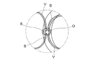
図5は図4の位置12a’と図4に示す眼底R1−R2を結ぶ線で形成される断面図であり、眼底で最も凹凸がある乳頭部Oを示している。位置12a’から射出された照明光は乳頭部Oに対して角度を持っているため、眼底の凹凸に対応して照明光が遮光された2個所がドットで示す陰影部Sとなる。
FIG. 5 is a sectional view formed by a line connecting the
図6は眼底での反射光を基に撮影された眼底画像の陰影部Sを有する立体的な画像を示している。なお、図6では網膜上の血管Vについても、乳頭部Oほどではないが網膜面に対して凸部であるため、同様に陰影部Sが生じている。 FIG. 6 shows a three-dimensional image having a shaded portion S of a fundus image taken on the basis of light reflected from the fundus. In FIG. 6, the blood vessel V on the retina is not as large as the papilla O but is a convex portion with respect to the retinal surface, so that a shadow portion S is similarly generated.
検者が被検眼Eの眼底を通常のカラー撮影を行う場合には、図7に示す撮影モード選択手段24により、「カラー撮影」の釦をクリックする。「カラー撮影」が選択されると、光量バランス変更手段23は左右眼検知手段25の結果によらず、撮影用照明光源12の全てのLED素子12a、・・・が同じ光量になるように駆動し、眼底を均一に照射するように制御する。検者が図示しない撮影スイッチを押すことにより、跳ね上げミラー17の跳ね上げに同期して、光量バランス変更手段23を駆動して撮影用照明光源12の全てのLED素子12a、・・・を発光する。
When the examiner performs normal color photographing of the fundus of the eye E, the “color photographing” button is clicked by the photographing mode selection means 24 shown in FIG. When “color photographing” is selected, the light quantity balance changing
検者が撮影モード選択手段24で「カラー立体撮影」の釦をクリックすると、光量バランス変更手段23は左右眼検知手段25の結果、例えば左眼を受け、撮影スイッチが押されると、LED素子12aを駆動して黄斑部mの反対側に陰影部Sを形成させる。即ち、撮影用照明光源12のLED素子12aを他のLED素子12xよりも強く発光させ、これにより図4に示す位置12a’から発光がなされ、図6に示すような眼底画像を得ることができる。
When the examiner clicks the “color stereoscopic photographing” button in the photographing
次に、検者が反対眼を撮影するために眼底カメラを右眼側に移動させて左右眼を切換え、撮影モード選択手段24で「カラー立体撮影」の釦をクリックする。これにより、光量バランス変更手段23は左右眼検知手段25の結果(右眼)を受け、撮影スイッチが押されると、黄斑部m側に陰影部Sが形成させる。即ち、撮影用照明光源12のLED素子12bだけを他のLED素子12xよりも強く発光させると、撮影画像は左眼と同様に、黄斑部m側に陰影部のある眼底画像を得ることができる。
Next, the examiner moves the fundus camera to the right eye side to photograph the opposite eye, switches the left and right eyes, and clicks the “color stereoscopic photographing” button in the photographing mode selection means 24. Thereby, the light quantity balance changing means 23 receives the result (right eye) of the left and right
これらの実施例の他に、「カラー立体撮影」時に撮影用照明光源12の一部のみ、例えばLED素子12aのみを発光し、他のLED素子12xを消灯して、スリット状光束で撮影することも可能である。
In addition to these embodiments, only a part of the illuminating
1 観察用照明光源
9 孔あきミラー
12 撮影用照明光源
12a、・・・ LED素子
13 対物レンズ
18 撮像手段
22 撮像素子
23 光量バランス変更手段
24 撮影モード選択手段
25 左右眼検知手段
DESCRIPTION OF
Claims (18)
前記複数の白色LED素子のうち一部の白色LED素子を他の白色LED素子よりも強く発光させるように、前記複数の白色LED素子の一部からの発光光量を選択的に変更する変更手段と、
を有することを特徴とする眼科装置。 Illuminating means for light irradiation of the subject's eye with visible light from the visible light source including a plurality of white LED devices,
Changing means for selectively changing the amount of light emitted from a part of the plurality of white LED elements so that some of the plurality of white LED elements emit light more strongly than other white LED elements ; ,
An ophthalmologic apparatus comprising:
前記照明手段が、前記複数の白色LED素子のうち一部の白色LED素子を他の白色LED素子よりも強く発光して前記被検眼の眼底を光軸外から照明し、
前記撮像手段が、前記一部の白色LED素子を他の白色LED素子よりも強く発光して前記眼底を光軸外から照明することにより該眼底において該眼底の凹凸に対応した陰影部が形成された状態で、該眼底を撮像することを特徴とする請求項1に記載の眼科装置。 It has sensitivity in the visible wavelength region, and has imaging means for receiving reflected light from the fundus of the eye to be examined and imaging the fundus,
The illumination means, the fundus emission to the subject's eye stronger than other white LED element part of the white LED element of the plurality of white LED devices were illuminated from outside the optical axis,
The imaging unit emits the white LED elements more strongly than the other white LED elements to illuminate the fundus from the optical axis, so that a shadow portion corresponding to the unevenness of the fundus is formed on the fundus. The ophthalmologic apparatus according to claim 1 , wherein the fundus is imaged in a state in which the eye is in contact.
前記変更手段は、前記左右眼検知手段の出力に基づいて、前記複数の白色LED素子における前記強く発光する白色LED素子を変更することを特徴とする請求項1乃至4のいずれか1項に記載の眼科装置。 Left and right eye detection means for detecting the left and right eye switching of the eye to be examined;
5. The change according to claim 1 , wherein the changing unit changes the strongly emitting white LED element in the plurality of white LED elements based on an output of the left and right eye detecting unit. Ophthalmic equipment.
前記変更手段が、前記立体撮影モードが選択された場合、前記複数の白色LED素子のうち一部の白色LED素子を他の白色LED素子よりも強く発光させるように、前記複数の白色LED素子の一部からの発光光量を選択的に変更することを特徴とする請求項1乃至5のいずれか1項に記載の眼科装置。 Having a shooting mode selection means for selecting one of a plurality of shooting modes including a stereoscopic shooting mode;
The changing means, when the three dimensional mode is selected, a part of the white LED element of the plurality of white LED devices so as to strongly emitting light than other white LED device, the plurality of white LED devices The ophthalmic apparatus according to claim 1, wherein the amount of light emitted from a part of the eye is selectively changed.
前記変更手段が、前記カラー撮影モードが選択された場合、前記複数の白色LED素子が発光する光量が略均一になるように、前記複数の白色LED素子の一部からの発光光量を選択的に変更することを特徴とする請求項6に記載の眼科装置。When the color photographing mode is selected, the changing unit selectively selects the amount of light emitted from a part of the plurality of white LED elements so that the amount of light emitted by the plurality of white LED elements is substantially uniform. The ophthalmic apparatus according to claim 6, wherein the ophthalmic apparatus is changed.
前記複数の白色LED素子が、前記開口部に沿って離散的に配置されることを特徴とする請求項1乃至8のいずれか1項に記載の眼科装置。The ophthalmologic apparatus according to any one of claims 1 to 8, wherein the plurality of white LED elements are discretely arranged along the opening.
前記複数の白色LED素子を含む可視光源からの可視光で被検眼を照明する工程と、Illuminating the subject's eye with visible light from a visible light source comprising the plurality of white LED elements;
を有することを特徴とする眼科装置の制御方法。A method for controlling an ophthalmic apparatus, comprising:
前記変更する工程において、前記立体撮影モードが選択された場合、前記複数の白色LED素子のうち一部の白色LED素子を他の白色LED素子よりも強く発光させるように、前記複数の白色LED素子の一部からの発光光量を選択的に変更することを特徴とする請求項13乃至15のいずれか1項に記載の眼科装置の制御方法。In the step of changing, when the stereoscopic shooting mode is selected, the plurality of white LED elements so that some white LED elements out of the plurality of white LED elements emit light more strongly than other white LED elements. The method for controlling an ophthalmologic apparatus according to any one of claims 13 to 15, wherein the amount of light emitted from a part of the device is selectively changed.
Priority Applications (2)
| Application Number | Priority Date | Filing Date | Title |
|---|---|---|---|
| JP2009032766A JP5371472B2 (en) | 2009-02-16 | 2009-02-16 | Ophthalmic equipment |
| US12/704,415 US8313195B2 (en) | 2009-02-16 | 2010-02-11 | Fundus camera |
Applications Claiming Priority (1)
| Application Number | Priority Date | Filing Date | Title |
|---|---|---|---|
| JP2009032766A JP5371472B2 (en) | 2009-02-16 | 2009-02-16 | Ophthalmic equipment |
Related Child Applications (1)
| Application Number | Title | Priority Date | Filing Date |
|---|---|---|---|
| JP2013194192A Division JP5787954B2 (en) | 2013-09-19 | 2013-09-19 | Ophthalmic apparatus and control method thereof |
Publications (3)
| Publication Number | Publication Date |
|---|---|
| JP2010187746A JP2010187746A (en) | 2010-09-02 |
| JP2010187746A5 JP2010187746A5 (en) | 2012-01-05 |
| JP5371472B2 true JP5371472B2 (en) | 2013-12-18 |
Family
ID=42559613
Family Applications (1)
| Application Number | Title | Priority Date | Filing Date |
|---|---|---|---|
| JP2009032766A Expired - Fee Related JP5371472B2 (en) | 2009-02-16 | 2009-02-16 | Ophthalmic equipment |
Country Status (2)
| Country | Link |
|---|---|
| US (1) | US8313195B2 (en) |
| JP (1) | JP5371472B2 (en) |
Families Citing this family (13)
| Publication number | Priority date | Publication date | Assignee | Title |
|---|---|---|---|---|
| JP5981722B2 (en) * | 2011-04-27 | 2016-08-31 | キヤノン株式会社 | Ophthalmic equipment |
| US20150021228A1 (en) | 2012-02-02 | 2015-01-22 | Visunex Medical Systems Co., Ltd. | Eye imaging apparatus and systems |
| US9655517B2 (en) | 2012-02-02 | 2017-05-23 | Visunex Medical Systems Co. Ltd. | Portable eye imaging apparatus |
| US9351639B2 (en) | 2012-03-17 | 2016-05-31 | Visunex Medical Systems Co. Ltd. | Eye imaging apparatus with a wide field of view and related methods |
| JP2014094117A (en) * | 2012-11-09 | 2014-05-22 | Canon Inc | Ophthalmologic photography apparatus |
| US9597009B2 (en) | 2013-12-19 | 2017-03-21 | Novartis Ag | Marker-based tool tracking |
| US9986908B2 (en) | 2014-06-23 | 2018-06-05 | Visunex Medical Systems Co. Ltd. | Mechanical features of an eye imaging apparatus |
| US9848773B2 (en) | 2015-01-26 | 2017-12-26 | Visunex Medical Systems Co. Ltd. | Disposable cap for an eye imaging apparatus and related methods |
| DE102015002729A1 (en) * | 2015-02-27 | 2016-09-01 | Carl Zeiss Meditec Ag | Ophthalmic laser therapy device and method for generating corneal access incisions |
| US20160331584A1 (en) * | 2015-05-14 | 2016-11-17 | Novartis Ag | Surgical tool tracking to control surgical system |
| US10973585B2 (en) | 2016-09-21 | 2021-04-13 | Alcon Inc. | Systems and methods for tracking the orientation of surgical tools |
| JP6691596B2 (en) * | 2018-12-14 | 2020-04-28 | 株式会社トプコン | Ophthalmic imaging device |
| WO2021199772A1 (en) * | 2020-03-31 | 2021-10-07 | 国立大学法人東北大学 | Device for estimating state of eyeball internal tissue and method therefor |
Family Cites Families (9)
| Publication number | Priority date | Publication date | Assignee | Title |
|---|---|---|---|---|
| AUPP062197A0 (en) * | 1997-11-28 | 1998-01-08 | Lions Eye Institute Of Western Australia Incorporated, The | Stereo scanning laser ophthalmoscope |
| JP4666821B2 (en) * | 2001-06-29 | 2011-04-06 | キヤノン株式会社 | Ophthalmic equipment |
| US6749310B2 (en) * | 2001-09-07 | 2004-06-15 | Contrast Lighting Services, Inc. | Wide area lighting effects system |
| US7256833B2 (en) * | 2002-05-22 | 2007-08-14 | Avago Technologies Ecbu Ip (Singapore) Pte. Ltd. | Method and apparatus for automatically optimizing optical contrast in automated equipment |
| JP4551727B2 (en) * | 2004-09-24 | 2010-09-29 | キヤノン株式会社 | Ophthalmic imaging equipment |
| JP4744870B2 (en) | 2004-12-22 | 2011-08-10 | 興和株式会社 | Ophthalmic imaging equipment |
| JP2007029726A (en) | 2005-07-22 | 2007-02-08 | Carl Zeiss Meditec Ag | Ring light fundus camera |
| JP5006585B2 (en) * | 2006-06-20 | 2012-08-22 | 興和株式会社 | Handheld fundus imaging device |
| JP5031405B2 (en) * | 2007-03-02 | 2012-09-19 | キヤノン株式会社 | Ophthalmic photographing apparatus, control method and program for ophthalmic photographing apparatus |
-
2009
- 2009-02-16 JP JP2009032766A patent/JP5371472B2/en not_active Expired - Fee Related
-
2010
- 2010-02-11 US US12/704,415 patent/US8313195B2/en not_active Expired - Fee Related
Also Published As
| Publication number | Publication date |
|---|---|
| US20100208202A1 (en) | 2010-08-19 |
| US8313195B2 (en) | 2012-11-20 |
| JP2010187746A (en) | 2010-09-02 |
Similar Documents
| Publication | Publication Date | Title |
|---|---|---|
| JP5371472B2 (en) | Ophthalmic equipment | |
| JP6003292B2 (en) | Fundus photographing device | |
| JP2007513703A (en) | Retina imaging system | |
| US20130208243A1 (en) | Ophthalmologic apparatus, method for controlling ophthalmologic apparatus, and storage medium | |
| JP2007029726A (en) | Ring light fundus camera | |
| JP6585897B2 (en) | Ophthalmic imaging equipment | |
| JP7214880B2 (en) | OPHTHALMIC DEVICE, CONTROL METHOD THEREOF, AND PROGRAM | |
| JP2017012663A (en) | Ophthalmic photographing apparatus, control method thereof and program | |
| JP2016185192A (en) | Ophthalmologic apparatus, and control method of ophthalmologic apparatus | |
| WO2018135175A1 (en) | Ophthalmological device | |
| JP2007275160A (en) | Ophthalmologic apparatus | |
| JP2014079392A (en) | Ophthalmology imaging apparatus | |
| JP6407631B2 (en) | Ophthalmic equipment | |
| JP2017099717A (en) | Ophthalmic photographing apparatus | |
| JP7266375B2 (en) | Ophthalmic device and method of operation thereof | |
| JP5522841B2 (en) | Fundus photographing device | |
| JP2019150425A (en) | Eyeground imaging apparatus | |
| JP2022027987A (en) | Ophthalmologic apparatus | |
| JP5787954B2 (en) | Ophthalmic apparatus and control method thereof | |
| JP2017143919A (en) | Ophthalmologic apparatus | |
| JP2017143918A (en) | Ophthalmologic apparatus | |
| JP2016010630A (en) | Ophthalmologic photographing apparatus, photographing control method and program | |
| JP6912554B2 (en) | Ophthalmic equipment | |
| JP2018051340A (en) | Ophthalmologic apparatus | |
| JP7469090B2 (en) | Ophthalmic device, control method thereof, and program |
Legal Events
| Date | Code | Title | Description |
|---|---|---|---|
| RD01 | Notification of change of attorney |
Free format text: JAPANESE INTERMEDIATE CODE: A7421 Effective date: 20100630 |
|
| A521 | Request for written amendment filed |
Free format text: JAPANESE INTERMEDIATE CODE: A523 Effective date: 20111110 |
|
| A621 | Written request for application examination |
Free format text: JAPANESE INTERMEDIATE CODE: A621 Effective date: 20111110 |
|
| A977 | Report on retrieval |
Free format text: JAPANESE INTERMEDIATE CODE: A971007 Effective date: 20121211 |
|
| A131 | Notification of reasons for refusal |
Free format text: JAPANESE INTERMEDIATE CODE: A131 Effective date: 20121225 |
|
| A521 | Request for written amendment filed |
Free format text: JAPANESE INTERMEDIATE CODE: A523 Effective date: 20130130 |
|
| TRDD | Decision of grant or rejection written | ||
| A01 | Written decision to grant a patent or to grant a registration (utility model) |
Free format text: JAPANESE INTERMEDIATE CODE: A01 Effective date: 20130820 |
|
| A61 | First payment of annual fees (during grant procedure) |
Free format text: JAPANESE INTERMEDIATE CODE: A61 Effective date: 20130917 |
|
| LAPS | Cancellation because of no payment of annual fees |