JP5369741B2 - Vibrating piece and vibrator - Google Patents
Vibrating piece and vibrator Download PDFInfo
- Publication number
- JP5369741B2 JP5369741B2 JP2009029895A JP2009029895A JP5369741B2 JP 5369741 B2 JP5369741 B2 JP 5369741B2 JP 2009029895 A JP2009029895 A JP 2009029895A JP 2009029895 A JP2009029895 A JP 2009029895A JP 5369741 B2 JP5369741 B2 JP 5369741B2
- Authority
- JP
- Japan
- Prior art keywords
- wiring
- vibrating
- vibrating arm
- base
- electrode
- Prior art date
- Legal status (The legal status is an assumption and is not a legal conclusion. Google has not performed a legal analysis and makes no representation as to the accuracy of the status listed.)
- Active
Links
- 239000010408 film Substances 0.000 description 29
- 239000000919 ceramic Substances 0.000 description 13
- 230000004048 modification Effects 0.000 description 9
- 238000012986 modification Methods 0.000 description 9
- 239000000463 material Substances 0.000 description 6
- 239000000853 adhesive Substances 0.000 description 3
- 230000001070 adhesive effect Effects 0.000 description 3
- 238000005516 engineering process Methods 0.000 description 3
- 238000000206 photolithography Methods 0.000 description 3
- 239000003566 sealing material Substances 0.000 description 3
- 229910052710 silicon Inorganic materials 0.000 description 3
- 239000010703 silicon Substances 0.000 description 3
- 239000010409 thin film Substances 0.000 description 3
- 229910013641 LiNbO 3 Inorganic materials 0.000 description 2
- 230000001154 acute effect Effects 0.000 description 2
- 239000013078 crystal Substances 0.000 description 2
- 238000010586 diagram Methods 0.000 description 2
- 229910052737 gold Inorganic materials 0.000 description 2
- 239000007769 metal material Substances 0.000 description 2
- 239000010453 quartz Substances 0.000 description 2
- VYPSYNLAJGMNEJ-UHFFFAOYSA-N silicon dioxide Inorganic materials O=[Si]=O VYPSYNLAJGMNEJ-UHFFFAOYSA-N 0.000 description 2
- 229910004298 SiO 2 Inorganic materials 0.000 description 1
- 238000005452 bending Methods 0.000 description 1
- 230000000694 effects Effects 0.000 description 1
- 239000002184 metal Substances 0.000 description 1
- 229910052751 metal Inorganic materials 0.000 description 1
- 230000010355 oscillation Effects 0.000 description 1
Images


Classifications
-
- H—ELECTRICITY
- H03—ELECTRONIC CIRCUITRY
- H03H—IMPEDANCE NETWORKS, e.g. RESONANT CIRCUITS; RESONATORS
- H03H9/00—Networks comprising electromechanical or electro-acoustic devices; Electromechanical resonators
- H03H9/15—Constructional features of resonators consisting of piezoelectric or electrostrictive material
- H03H9/21—Crystal tuning forks
-
- H—ELECTRICITY
- H03—ELECTRONIC CIRCUITRY
- H03H—IMPEDANCE NETWORKS, e.g. RESONANT CIRCUITS; RESONATORS
- H03H9/00—Networks comprising electromechanical or electro-acoustic devices; Electromechanical resonators
- H03H9/02—Details
- H03H9/05—Holders; Supports
- H03H9/0504—Holders; Supports for bulk acoustic wave devices
- H03H9/0509—Holders; Supports for bulk acoustic wave devices consisting of adhesive elements
-
- H—ELECTRICITY
- H03—ELECTRONIC CIRCUITRY
- H03H—IMPEDANCE NETWORKS, e.g. RESONANT CIRCUITS; RESONATORS
- H03H9/00—Networks comprising electromechanical or electro-acoustic devices; Electromechanical resonators
- H03H9/02—Details
- H03H9/05—Holders; Supports
- H03H9/10—Mounting in enclosures
- H03H9/1007—Mounting in enclosures for bulk acoustic wave [BAW] devices
- H03H9/1014—Mounting in enclosures for bulk acoustic wave [BAW] devices the enclosure being defined by a frame built on a substrate and a cap, the frame having no mechanical contact with the BAW device
- H03H9/1021—Mounting in enclosures for bulk acoustic wave [BAW] devices the enclosure being defined by a frame built on a substrate and a cap, the frame having no mechanical contact with the BAW device the BAW device being of the cantilever type
Description
本発明は、振動腕を有する振動片および振動子に関する。 The present invention relates to a resonator element having a vibrating arm and a vibrator.
振動腕を有する振動子において、振動腕が屈曲振動のように面内で振動するのではなく
、振動腕の厚み方向に振動する振動片が知られている。この振動片は、一般に複数本の振
動腕を有し、隣り合う振動腕が反対方向の振動を交互に繰り返す、ウォークモード振動を
行う振動片である。
例えば、特許文献1にはウォークモード振動を利用した角速度センサーが開示されてい
る。この角速度センサーはシリコンなどで形成された3本のアーム(振動腕)を有し、そ
れぞれのアームの一面にアーム駆動用の下層電極(下部電極)、圧電薄膜(圧電膜)、上
層電極(上部電極)がこの順に形成されている。これらの下層電極、圧電薄膜、上層電極
にて圧電素子が形成され、圧電薄膜の逆圧電効果により振動片の厚み方向に振動が可能で
ある。そして、隣り合うアームとは逆方向に振動するように各電極の極性が設定されてい
る。
In a vibrator having a vibrating arm, a vibrating piece is known that vibrates in the thickness direction of the vibrating arm, instead of vibrating in-plane like a bending vibration. This resonator element is a resonator element that has a plurality of vibrating arms and performs walk mode vibration in which adjacent vibrating arms repeat vibrations in opposite directions alternately.
For example,
このような振動片において、下層電極および上層電極に接続される配線は片方の面に配
置され、それぞれの配線は互いの交差を回避するように配置される。このため、配線の配
置が複雑になり、かつ大きな面積が必要となる。
また、特許文献1のような構成では、特に振動片の小型化を図る場合に、振動片の面積
が小さくなるため配線経路を確保するのが難しく、振動片の小型化が困難である。
In such a resonator element, the wiring connected to the lower layer electrode and the upper layer electrode is disposed on one surface, and the respective wirings are disposed so as to avoid crossing each other. For this reason, the arrangement of wiring is complicated and a large area is required.
Further, in the configuration as in
本発明は上記課題の少なくとも一部を解決するためになされたものであり、以下の形態
または適用例として実現することが可能である。
SUMMARY An advantage of some aspects of the invention is to solve at least a part of the problems described above, and the invention can be implemented as the following forms or application examples.
[適用例1]本適用例にかかる振動片は、基部と、前記基部から延出し、且つ、互いに表裏関係にある第1面および第2面と、前記第1面および前記第2面を連結する側面と、を備えた振動腕と、前記振動腕の前記第1面に設けられた下部電極と、前記下部電極の上方に形成された上部電極と、前記下部電極および前記上部電極の間に設けられた圧電膜と、前記下部電極に接続される第1配線と、前記上部電極に接続される第2配線と、を含み、
前記第2配線は、前記側面を経て前記第2面に引き出されていることを特徴とする。
[Application Example 1] A resonator element according to this application example connects a base, a first surface and a second surface that extend from the base and are in a front-back relationship with each other, and the first surface and the second surface. A vibrating arm, a lower electrode provided on the first surface of the vibrating arm, an upper electrode formed above the lower electrode, and between the lower electrode and the upper electrode A piezoelectric film provided; a first wiring connected to the lower electrode; and a second wiring connected to the upper electrode;
Before Stories second wiring is characterized in that through the side is drawn to the second surface.
この構成によれば、上部電極に接続される配線が振動腕を囲むように、振動腕の第1面
から振動腕の側面を経て振動腕の第2面に引き出されている。
このように、振動腕の第1面からその裏面である第2面に配線を引き出すことで、容易
に配線を裏面に引き出せる。そして、振動片の表裏を配線の配置に利用できることから、
配線が配置できる面積が拡大し、配線の配置の自由度が増す。また、限られたスペースに
おいても配線の配置が可能となり、振動片の小型化を図ることができる。
According to this configuration, the wiring connected to the upper electrode is drawn from the first surface of the vibrating arm to the second surface of the vibrating arm through the side surface of the vibrating arm so as to surround the vibrating arm.
In this way, by drawing the wiring from the first surface of the vibrating arm to the second surface, which is the back surface, the wiring can be easily pulled out to the back surface. And because the front and back of the resonator element can be used for wiring arrangement,
The area in which the wiring can be arranged is increased, and the degree of freedom in arranging the wiring is increased. In addition, the wiring can be arranged even in a limited space, and the vibration piece can be reduced in size.
[適用例2]上記適用例にかかる振動片において、前記基部には、前記第2配線に接続されるマウント電極が設けられていることが望ましい。 Application Example 2 In the resonator element according to the application example described above, it is preferable that the base portion is provided with a mount electrode connected to the second wiring.
この構成によれば、振動片の基部の端部に、配線に接続されるマウント電極が形成され
、このマウント電極を介して、上部電極および下部電極と電気的導通をとることができる
。また、振動片をマウント電極部分において導電性接着剤などで固定することで、片持ち
構造で振動片を保持でき、振動片の特性を良好に実現できる。
According to this configuration, the mount electrode connected to the wiring is formed at the end of the base portion of the resonator element, and electrical conduction can be established between the upper electrode and the lower electrode via the mount electrode. In addition, by fixing the resonator element with a conductive adhesive or the like at the mount electrode portion, the resonator element can be held in a cantilever structure, and the characteristics of the resonator element can be satisfactorily realized.
[適用例3]上記適用例にかかる振動片において、前記基部は前記振動腕よりも厚く、且つ、前記振動腕と前記基部とが連結される部分が前記振動腕から前記基部に向かって連続して厚みが厚くなっていて傾斜部を有し、前記配線は、前記傾斜部を通っていることが望ましい。 Application Example 3 In the resonator element according to the application example described above, the base is thicker than the vibrating arm, and a portion where the vibrating arm and the base are connected is continuous from the vibrating arm toward the base. It is desirable that the thickness is thick and has an inclined portion, and the wiring passes through the inclined portion .
この構成によれば、振動腕の厚みより基部の厚みが厚く形成された振動片において、基
部の一部が振動腕から基部の端部に向かって連続して厚みが厚くなるように形成されてい
る。基部の振動腕との連結部分が斜面状となっており、振動腕から基部に引き回された配
線は、この斜面を通ってマウント電極などに接続される。
このような、斜面部を形成しないで振動腕と基部を連結した場合には、振動腕と基部の
境に段差が生ずることになる。本適用例では、連結部分に斜面部を有しているため、段差
を配線が交差する場合に比べて、配線が鋭角な稜を交差することがなく、この部分におけ
る配線の断線を防止できる。また、振動腕と基部との連結部分に段差がないため、配線の
作成にフォトリソグラフィー技術を利用した場合にも、レジストの露光が確実に行われ、
配線に断線が生じることなく容易に配線を作成できる。
According to this configuration, in the resonator element in which the base portion is thicker than the thickness of the vibrating arm, a part of the base portion is formed so as to continuously increase from the vibrating arm toward the end portion of the base portion. Yes. The connecting portion of the base portion with the vibrating arm has a slope shape, and the wiring routed from the vibrating arm to the base portion is connected to a mount electrode or the like through this slope surface.
When the vibrating arm and the base are connected without forming the inclined surface, a step is generated at the boundary between the vibrating arm and the base. In this application example, since the connecting portion has the slope portion, the wiring does not cross an acute edge compared to the case where the wiring intersects the step, and disconnection of the wiring in this portion can be prevented. In addition, since there is no step at the connecting portion between the vibrating arm and the base, the resist is reliably exposed even when photolithography technology is used to create the wiring.
Wiring can be easily created without disconnection in the wiring.
[適用例4]上記適用例にかかる振動片において、前記振動腕は、3以上の奇数本を備え、厚み方向に振動し、かつ隣り合う前記振動腕が互いに反対方向に振動することが望ましい。 Application Example 4 In the resonator element according to the application example described above, it is preferable that the vibrating arms include an odd number of three or more, vibrate in the thickness direction, and adjacent vibrating arms vibrate in opposite directions.
[適用例5]本適用例にかかる振動子は、上記に記載の振動片と、前記振動片を収納する収容器と、を有し、前記振動片が前記収容器内に気密に収容されていることを特徴とする。 Application Example 5 A vibrator according to this application example includes the above-described vibration piece and a container that stores the vibration piece, and the vibration piece is housed in the container in an airtight manner. It is characterized by being.
この構成によれば、上記の振動片が収容器に収容されていることから、振動片を小型化
でき、小型化された振動子を提供することができる。
According to this configuration, since the vibrating piece is housed in the container, the vibrating piece can be reduced in size, and a downsized vibrator can be provided.
以下、本発明を具体化した実施形態について図面に従って説明する。なお、以下の説明
に用いる各図面では、各部材を認識可能な大きさとするため、各部材の寸法の割合を適宜
変更している。
(第1の実施形態)
DESCRIPTION OF EXEMPLARY EMBODIMENTS Hereinafter, embodiments of the invention will be described with reference to the drawings. In the drawings used for the following description, the ratio of dimensions of each member is appropriately changed so that each member has a recognizable size.
(First embodiment)
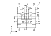
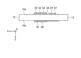
図1は本実施形態の振動片の構成を示す概略平面図である。図2は本実施形態の振動片
の構成を示し、図1の裏面の概略平面図である。図3は圧電素子の構成を示し図1のA−
A断線に沿う概略断面図である。図4は図1のB−B断線に沿う概略断面図である。
図1、図2に示すように、振動片1は水晶またはシリコンなどの基材を用いて振動片1
が形成されている。振動片1は直交座標系でXY平面に展開したときに、Z方向を厚みと
する形態である。振動片1は3本の振動腕11,12,13を有し、振動腕11,12,
13はX方向に並列されると共に、Y方向に互いに平行に延在している。そして、振動腕
11,12,13は基部15に連結され、各振動腕11,12,13が片持ち構造となる
振動片1を構成している。また、振動腕11,12,13のZ方向に垂直な面である第1
面16aと第2面16bとが対向し、この第1面16aと第2面16bの間の寸法が振動
腕11,12,13の厚みを規定する。
FIG. 1 is a schematic plan view showing the configuration of the resonator element according to this embodiment. FIG. 2 is a schematic plan view of the back surface of FIG. 1 showing the configuration of the resonator element according to the present embodiment. FIG. 3 shows the configuration of the piezoelectric element and is shown in FIG.
It is a schematic sectional drawing in alignment with A disconnection. 4 is a schematic cross-sectional view taken along the line BB in FIG.
As shown in FIG. 1 and FIG. 2, the
Is formed. The
13 are juxtaposed in the X direction and extend parallel to each other in the Y direction. The vibrating
The
各振動腕11,12,13の基部15に近い位置にはそれぞれ圧電素子61,62,6
3が形成されている。
振動腕11に形成された圧電素子61は、図3に示すように、下部電極21、圧電膜3
1、上部電極51が積層されて形成されている。
下部電極21は、振動腕11の厚みを規定する対向する面のうちの第1面16a上に設
けられている。また、この下部電極21は振動腕11の幅と同等の幅で形成されている。
下部電極21の上には、下部電極21を覆い振動腕11の周囲を囲むように側面および第
2面16bにかけて圧電膜31が形成されている。そして、圧電膜31の上には、圧電膜
31を覆う上部電極51が形成されている。さらに、上部電極51に接続される配線58
が、振動腕11を囲むように振動腕11の側面を経て第2面16bに引き出されている。
3 is formed.
As shown in FIG. 3, the
1. An
The
On the
Is drawn out to the
このようにして、圧電膜31を挟んで下部電極21と上部電極51とが対向することで
圧電素子61が形成され、各電極間に正負の電圧をかけることで圧電膜31が圧縮または
伸長することが可能である。そして、圧電膜31が圧縮または伸長することで、振動腕1
1をZ方向に変位させることができる。
同様に、圧電素子62,63は、下部電極22,23、圧電膜32,33、上部電極5
2,53が積層されて形成されている。さらに、上部電極52,53に接続される配線5
8が、振動腕12,13を囲むように振動腕12,13の側面を経て第2面16bに引き
出されている。
In this manner, the
1 can be displaced in the Z direction.
Similarly, the
2 and 53 are laminated. Further, the
8 is drawn out to the
なお、下部電極21,22,23、上部電極51,52,53およびこれらの電極に接
続される配線28,58は連続して形成されているため、本実施形態の説明では下部電極
21,22,23および上部電極51,52,53は、これらの電極が圧電膜31,32
,33を挟んで重なり合う部分を言い、それ以外はそれぞれの電極に接続する配線28,
58と呼ぶ。
また、下部電極21,22,23と上部電極51,52,53との間にSiO2、Si2
N3などの絶縁膜を設け、下部電極21,22,23と上部電極51,52,53の間の
電気的短絡を確実に防止しても良い。
Since the
, 33 between the wirings 28 connected to the respective electrodes.
58.
Further, between the
An insulating film such as N 3 may be provided to reliably prevent an electrical short circuit between the
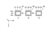
次に図1、図2、図4に示すように、下部電極21,22,23に接続される配線28
および上部電極51,52,53に接続される配線58は、振動片1の基部15に引き出
され、パッケージなどの基台に固定されて電気的導通が図られるマウント電極65,66
に接続されている。また、下部電極22と上部電極51,53とを繋ぎ、圧電素子61,
63と圧電素子62との極性が逆になるように接続部57が設けられている。
Next, as shown in FIGS. 1, 2, and 4, the
The
It is connected to the. Further, the
A connecting
なお、下部電極および上部電極はAu、Al、Tiなどの金属材料を利用できる。また
、下部電極および上部電極は下地との密着強度を向上させるために下地との間にCr膜を
備えても良い。圧電膜としては、ZnO、AlN、PZT、LiNbO3、KNbO3など
の材料を使用することができるが、特にZnO、AlNがより良好な特性が得られ好まし
い。
また、振動片1の基材として水晶を用いる場合には、Xカット板、ATカット板、Zカ
ット板などを利用することができる。
The lower electrode and the upper electrode can use metal materials such as Au, Al, and Ti. The lower electrode and the upper electrode may be provided with a Cr film between the lower electrode and the upper electrode in order to improve the adhesion strength with the lower electrode. As the piezoelectric film, materials such as ZnO, AlN, PZT, LiNbO 3 , and KNbO 3 can be used. In particular, ZnO and AlN are preferable because better characteristics are obtained.
Further, when quartz is used as the base material of the
<下部電極および上部電極に接続される配線の構成>
次に、上記のような振動片1の下部電極および上部電極に接続される配線について詳し
く説明する。
図5は下部電極に接続される配線を示し、図5(a)は表(おもて)面の概略平面図、
図5(b)は裏面の概略平面図である。図6は上部電極に接続される配線を示し、図6(
a)は表(おもて)面の概略平面図、図6(b)は裏面の概略平面図である。
<Configuration of wiring connected to lower electrode and upper electrode>
Next, the wiring connected to the lower electrode and the upper electrode of the
FIG. 5 shows the wiring connected to the lower electrode, FIG. 5 (a) is a schematic plan view of the front (front) surface,
FIG. 5B is a schematic plan view of the back surface. FIG. 6 shows wiring connected to the upper electrode, and FIG.
a) is a schematic plan view of the front surface, and FIG. 6B is a schematic plan view of the back surface.
まず、図5(a)に示すように、下部電極21,22,23は振動腕11,12,13
の厚みを規定する対向する面のうちの第1面16a上に設けられている。
中央に位置する振動腕12に形成された下部電極22からは、同一面の基部15に配線
28が引き出されて、接続部27に接続されている。振動腕12の両側に位置する振動腕
11,13に形成された下部電極21,23からは、同一面の基部15に配線28が引き
出されて接続され、さらにこれらの配線28はマウント電極66に接続されている。また
、図5(b)に示すように、他方の面(裏面)には配線は形成されない。
First, as shown in FIG. 5A, the
Are provided on the
From the
次に図6に示すように、上部電極51,52,53は下部電極を覆う位置に形成される
。そして、上部電極51,52,53に接続される配線58が、振動腕11,12,13
を囲むように振動腕11,12,13の側面を経て第2面16bに引き出されている。
また振動片の表面では、図6(a)に示すように、振動腕12の両側に位置する振動腕
11,13に形成された上部電極51,53からは、基部15に配線58が引き出されて
、接続部57に接続されている。
一方、振動片の裏面では、図6(b)に示すように、中央に位置する振動腕12に形成
された上部電極52からは、基部15に配線58が引き出されて、マウント電極66に接
続されている。このマウント電極66は基部15の側面に形成された配線により振動片の
表面に引き回されて、表裏にマウント電極66が設けられている。
また、振動腕11に形成された上部電極51からは、基部15に配線58が引き出され
てマウント電極65に接続されている。このマウント電極65は基部15の側面に形成さ
れた配線により振動片の表面に引き回されて、表裏にマウント電極65が設けられている
。
Next, as shown in FIG. 6, the
Is drawn out to the
On the surface of the resonator element, as shown in FIG. 6A, the
On the other hand, on the back surface of the resonator element, as shown in FIG. 6B, the
Further, a
このような、下部電極21,22,23に接続される配線28および上部電極51,5
2,53に接続される配線58が構成され、下部電極側の接続部27と上部電極側の接続
部57が接続され、下部電極22と上部電極51,53が接続される。さらに、上部電極
51を通って上部電極側のマウント電極65に接続される。このようにして、下部電極2
2と上部電極51,53がマウント電極65に接続された配線となる。
また、下部電極側のマウント電極66と上部電極側のマウント電極66とが接続され、
下部電極21,23と上部電極52が接続される。このようにして、下部電極21,23
と上部電極52がマウント電極66に接続された配線となる。
2 and 53, the lower electrode
2 and the
The lower electrode
The
図7は、第1の実施形態における振動片の動作を説明する模式図である。
上記のような構成の振動片1は、各圧電素子(図示せず)に電圧を加えることで振動腕
はZ方向に変位する。そして、振動腕11と振動腕13は同じ極性の圧電素子が設けられ
ていることから、中央の振動腕12とその両脇の振動腕11,13は逆方向に振動し、交
番電圧を加えることで隣り合う振動腕が反対方向の振動を交互に繰り返す振動(ウォーク
モード振動)を行う。
FIG. 7 is a schematic diagram for explaining the operation of the resonator element according to the first embodiment.
In the
以上、本実施形態の振動片1は、上部電極51,52,53に接続される配線58がそ
れぞれの振動腕11,12,13を囲むように、振動腕11,12,13の第1面16a
から振動腕11,12,13の側面を経て振動腕11,12,13の第2面16bに引き
出されている。
このように、振動腕11,12,13の第1面16aからその裏面である第2面16b
に配線58を引き出すことで、容易に配線58を裏面に引き出せる。そして、振動腕11
,12,13の表裏を配線58の配置に利用できることから、配線58が配置できる面積
が拡大し、配線58の配置の自由度が増す。また、限られたスペースにおいても配線58
の配置が可能となり、振動片1の小型化を図ることができる。
(変形例)
As described above, in the
Is pulled out to the
Thus, from the
By pulling out the
, 12 and 13 can be used for the arrangement of the
Therefore, the size of the
(Modification)
また、振動腕の厚みより基部の厚みが厚く形成された振動片においても、本実施形態の
電極および配線の配置を利用することができる。
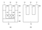
図8は振動腕の厚みより基部の厚みが厚く形成された振動片の変形例を示す概略断面図
である。この断面図は、前述した図4に相当する断面である。
この変形例では、振動片の平面形状、振動片に形成された上部電極、圧電膜、下部電極
、配線については第1の実施形態と同様な構成であり、振動片の断面形状のみが異なる。
以下の説明では、第1の実施形態と同様な構成要素については同符号を付し、説明を省
略する。
In addition, the arrangement of the electrodes and wirings of the present embodiment can also be used in a resonator element in which the thickness of the base is thicker than the thickness of the vibrating arm.
FIG. 8 is a schematic cross-sectional view showing a modified example of the resonator element in which the thickness of the base is thicker than the thickness of the vibrating arm. This cross-sectional view corresponds to FIG. 4 described above.
In this modification, the planar shape of the resonator element, the upper electrode, the piezoelectric film, the lower electrode, and the wiring formed on the resonator element are the same as those in the first embodiment, and only the sectional shape of the resonator element is different.
In the following description, components similar to those in the first embodiment are denoted by the same reference numerals, and description thereof is omitted.
図8(a)に示す振動片は、振動腕12aの第1面16a側は振動腕12aから基部1
5aまで平坦な面を有し、振動腕12aの第2面16b側は基部15aの一部に形成され
た斜面部17を介して振動腕12aに連結されている。このように、振動腕12aの第2
面16b側に斜面部17を設けることで、振動片の厚みが振動腕12aから基部15aの
端部に向かって連続して厚くなるように形成されている。そして、この斜面部17上に上
部電極52に接続される配線58が配置されている。
図8(b)に示す振動片は、振動腕12bの第1面16a側は基部15bの一部に形成
された斜面部17を介して振動腕12bに連結され、振動腕12bの第2面16b側は基
部15bの一部に形成された斜面部17を介して振動腕12bに連結されている。このよ
うに、振動腕12bの第1面16a側および第2面16b側に斜面部17を設けることで
、振動片の厚みが振動腕12bから基部15bの端部に向かって連続して厚くなるように
形成されている。そして、この斜面部17上に下部電極22に接続される配線28および
上部電極52に接続される配線58が配置されている。
In the vibrating piece shown in FIG. 8A, the
It has a flat surface up to 5a, and the
By providing the
In the vibrating piece shown in FIG. 8B, the
以上のように、振動腕の厚みより基部の厚みが厚く形成された振動片において、基部1
5a,15bの振動腕12a,12bとの連結部分が斜面部17を形成し、振動腕12a
,12bから基部15a,15bに引き回された配線28,58はこの斜面部17を通っ
てマウント電極などに接続される。
上記のような、斜面部17を形成しないで振動腕と基部を連結した場合には、振動腕と
基部の境に段差が生ずることになる。本変形例では、連結部分に斜面部17を有している
ため、段差を配線28,58が交差する場合に比べて、配線28,58が鋭角な稜を交差
することがなく、この部分における配線28,58の断線を防止できる。また、振動腕と
基部との連結部分に段差がないため、配線28,58の作成にフォトリソグラフィー技術
を利用した場合にも、レジストの露光が確実に行われ、配線に断線が生じることなく容易
に配線28,58を作成できる。
(第2の実施形態)
As described above, in the resonator element in which the thickness of the base is thicker than the thickness of the vibrating arm, the
The connecting portions of the vibrating
, 12b to the
When the vibrating arm and the base are connected without forming the
(Second Embodiment)
次に、第2の実施形態の振動片について説明する。本実施形態は、第1の実施形態と上
部電極および下部電極に接続する配線の配置が異なる。
図9は本実施形態の振動片の構成を示す概略平面図である。図10は本実施形態の振動
片の構成を示し、図9の裏面の概略平面図である。図11は圧電素子の構成を示し、図9
のC−C断線に沿う概略断面図である。図12は図9のD−D断線に沿う概略断面図であ
る。
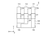
Next, the resonator element according to the second embodiment will be described. This embodiment is different from the first embodiment in the arrangement of wirings connected to the upper electrode and the lower electrode.
FIG. 9 is a schematic plan view showing the configuration of the resonator element according to this embodiment. FIG. 10 shows the configuration of the resonator element according to this embodiment, and is a schematic plan view of the back surface of FIG. FIG. 11 shows the configuration of the piezoelectric element.
It is a schematic sectional drawing in alignment with CC disconnection. FIG. 12 is a schematic sectional view taken along the line DD in FIG.
図9、図10に示すように、振動片2は水晶またはシリコンなどの基材を用いて振動片
2が形成されている。振動片2は直交座標系でXY平面に展開したときに、Z方向を厚み
とする形態である。振動片2は3本の振動腕111,112,113を有し、振動腕11
1,112,113はX方向に並列されると共に、Y方向に互いに平行に延在している。
そして、振動腕111,112,113は基部115に連結され、各振動腕111,11
2,113が片持ち構造となる振動片2を構成している。また、振動腕111,112,
113のZ方向に垂直な面である第1面116aと第2面116bとが対向し、この第1
面116aと第2面116bの間の寸法が振動腕111,112,113の厚みを規定す
る。
As shown in FIGS. 9 and 10, the
1, 112 and 113 are juxtaposed in the X direction and extend parallel to each other in the Y direction.
The vibrating
2 and 113 constitute a vibrating
The
The dimension between the
各振動腕111,112,113の基部115に近い位置にはそれぞれ圧電素子161
,162,163が形成されている。
振動腕111に形成された圧電素子161は、図11に示すように、下部電極121、
圧電膜131、上部電極151が積層されて形成されている。
下部電極121は、振動腕111の厚みを規定する対向する面のうち第1面116a上
に設けられている。さらに、下部電極121に接続される配線128が、振動腕111を
囲むように振動腕111の側面を経て第2面116bに引き出されている。下部電極12
1の上には、下部電極121を覆い振動腕111の周囲を囲んで圧電膜131が形成され
ている。そして、圧電膜131の上で、かつ下部電極121の上方に位置する場所に上部
電極151が設けられている。
, 162, 163 are formed.
As shown in FIG. 11, the
A
The
A
このようにして、圧電膜131を挟んで下部電極121と上部電極151とが対向する
ことで圧電素子161が形成され、各電極間に正負の電圧をかけることで圧電膜131が
圧縮または伸長することが可能である。そして、圧電膜131が圧縮または伸長すること
で、振動腕111をZ方向に変位させることができる。
同様に、圧電素子162,163は、下部電極122,123、圧電膜132,133
、上部電極152,153が積層されて形成されている。
さらに、下部電極122,123に接続される配線128が振動腕112,113の側面
を経て第2面116b側に引き出されている。
Thus, the
Similarly, the
The
Furthermore, the
なお、下部電極121,122,123、上部電極151,152,153およびこれ
らの電極に接続される配線128,158は連続して形成されているため、本実施形態の
説明では下部電極121,122,123および上部電極151,152,153は、こ
れらの電極が圧電膜131,132,133を挟んで重なり合う部分を言い、それ以外は
それぞれの電極に接続する配線128,158と呼ぶ。
また、下部電極121,122,123と上部電極151,152,153との間にS
iO2、Si2N3などの絶縁膜を設け、下部電極121,122,123と上部電極15
1,152,153の間の電気的短絡を確実に防止しても良い。
Since the
Further, between the
An insulating film such as iO 2 or Si 2 N 3 is provided, and the
An electrical short circuit between 1,152,153 may be reliably prevented.
次に、図9、図10、図12に示すように、下部電極121,122,123に接続さ
れる配線128および上部電極151,152,153に接続される配線158は振動片
2の基部115に引き出され、パッケージなどの基台に固定されて電気的導通が図られる
マウント電極165,166に接続されている。また、下部電極121,123と上部電
極152とを繋ぎ、圧電素子161,163と圧電素子162との極性が逆になるように
接続部157が設けられている。
Next, as shown in FIGS. 9, 10, and 12, the
なお、下部電極および上部電極はAu、Al、Tiなどの金属材料を利用できる。また
、下部電極および上部電極は下地との密着強度を向上させるために下地との間にCr膜を
備えても良い。圧電膜としては、ZnO、AlN、PZT、LiNbO3、KNbO3など
の材料を使用することができるが、特にZnO、AlNがより良好な特性が得られ好まし
い。
また、振動片2の基材として水晶を用いる場合には、Xカット板、ATカット板、Zカ
ット板などを利用することができる。
The lower electrode and the upper electrode can use metal materials such as Au, Al, and Ti. The lower electrode and the upper electrode may be provided with a Cr film between the lower electrode and the upper electrode in order to improve the adhesion strength with the lower electrode. As the piezoelectric film, materials such as ZnO, AlN, PZT, LiNbO 3 , and KNbO 3 can be used. In particular, ZnO and AlN are preferable because better characteristics are obtained.
Further, when quartz is used as the base material of the
<下部電極および上部電極に接続される配線の構成>
次に、上記のような振動片2の下部電極および上部電極に接続される配線について詳し
く説明する。
図13は下部電極に接続される配線を示し、図13(a)は表(おもて)面の概略平面
図、図13(b)は裏面の概略平面図である。図14は上部電極および上部電極に接続さ
れる配線を示し、図14(a)は表(おもて)面の概略平面図、図14(b)は裏面の概
略平面図である。
<Configuration of wiring connected to lower electrode and upper electrode>
Next, the wiring connected to the lower electrode and the upper electrode of the
13A and 13B show wirings connected to the lower electrode. FIG. 13A is a schematic plan view of the front surface, and FIG. 13B is a schematic plan view of the back surface. FIG. 14 shows an upper electrode and wiring connected to the upper electrode. FIG. 14A is a schematic plan view of the front surface, and FIG. 14B is a schematic plan view of the back surface.
まず、図13に示すように、下部電極121,122,123は振動腕111,112
,113の厚みを規定する対向する面のうちの第1面116a上に設けられている。
振動片の表面では、図13(a)に示すように、振動腕112の両側に位置する振動腕
111,113に形成された下部電極121,123からは、基部115に配線128が
引き出されて、接続部127に接続されている。
一方、振動片の裏面では、図13(b)に示すように、中央に位置する振動腕112に
形成された下部電極122からは、基部115に配線128が引き出されて、マウント電
極166に接続されている。このマウント電極166は基部115の側面に形成された配
線により振動片の表面に引き回されて、表裏にマウント電極166が設けられている。
また、振動腕111に形成された下部電極121からは、同一面の基部115に配線1
28が引き出されてマウント電極165に接続されている。このマウント電極165は基
部115の側面に形成された配線により振動片の表面に引き回されて、表裏にマウント電
極165が設けられている。
First, as shown in FIG. 13, the
, 113 are provided on the
On the surface of the resonator element, as shown in FIG. 13A, the
On the other hand, on the back surface of the resonator element, as shown in FIG. 13B, the
Further, from the
28 is extracted and connected to the
そして、上部電極151,152,153は下部電極121,122,123の上方の
位置に形成される。
図14に示すように、中央に位置する振動腕112に形成された上部電極152からは
、同一面の基部115に配線158が引き出されて、接続部157に接続されている。振
動腕112の両側に位置する振動腕111,113に形成された上部電極151,153
からは、同一面の基部115に配線158が引き出されて接続され、さらにこれらの配線
158はマウント電極166に接続されている。また、図14(b)に示すように、他方
の面(裏面)には配線は形成されない。
The
As shown in FIG. 14, a
The
このような、下部電極121,122,123および上部電極151,152,153
に接続される配線128,158が構成され、下部電極側の接続部127と上部電極側の
接続部157が接続され、下部電極121,123と上部電極152が接続される。そし
て、下部電極121を通ってマウント電極165に接続される。このようにして、下部電
極121,123と上部電極152がマウント電極165に接続された配線となる。
また、下部電極側のマウント電極166と上部電極側のマウント電極166とが接続さ
れ、下部電極122と上部電極151,153が接続される。このようにして、下部電極
122と上部電極151,153がマウント電極166に接続された配線となる。
Such
Further, the
上記のような構成の振動片2は、図7で説明したのと同様に、各圧電素子に電圧を加え
ることで振動腕はZ方向に変位する。そして、振動腕111と振動腕113は同じ極性の
圧電素子が設けられていることから、中央の振動腕112とその両脇の振動腕111,1
13は逆方向に振動し、交番電圧を加えることで隣り合う振動腕が反対方向の振動を交互
に繰り返す振動(ウォークモード振動)を行う。
In the vibrating
13 vibrates in the reverse direction, and by applying an alternating voltage, adjacent vibrating arms perform vibration (walk mode vibration) in which the vibration in the opposite direction is alternately repeated.
以上、本実施形態の振動片2は、下部電極121,122,123に接続される配線1
28がそれぞれの振動腕111,112,113を囲むように、振動腕111,112,
113の第1面116aから振動腕111,112,113の側面を経て振動腕111,
112,113の第2面116bに引き出されている。
このように、振動腕111,112,113の第1面116aからその裏面である第2
面116bに配線128を引き出すことで、容易に配線128を裏面に引き出せる。そし
て、振動片2の表裏を配線128の配置に利用できることから、配線128が配置できる
面積が拡大し、配線128の配置の自由度が増す。また、限られたスペースにおいても配
線128の配置が可能となり、振動片2の小型化を図ることができる。
(変形例)
As described above, the
Resonating
The vibrating
It is pulled out to the
As described above, the
By drawing the
(Modification)
また、振動腕の厚みより基部の厚みが厚く形成された振動片においても、本実施形態の
電極および配線の配置を利用することができる。
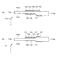
図15は振動腕の厚みより基部の厚みが厚く形成された振動片の変形例を示す概略断面
図である。この断面図は、前述した図12に相当する断面である。
この変形例では、振動片の平面形状、振動片に形成された上部電極、圧電膜、下部電極
、配線については第2の実施形態と同様な構成であり、振動片の断面形状のみが異なる。
以下の説明では、第2の実施形態と同様な構成要素については同符号を付し、説明を省
略する。
In addition, the arrangement of the electrodes and wirings of the present embodiment can also be used in a resonator element in which the thickness of the base is thicker than the thickness of the vibrating arm.
FIG. 15 is a schematic cross-sectional view showing a modification of the resonator element in which the base portion is thicker than the thickness of the vibrating arm. This cross-sectional view corresponds to FIG. 12 described above.
In this modification, the planar shape of the vibrating piece, the upper electrode, the piezoelectric film, the lower electrode, and the wiring formed on the vibrating piece have the same configuration as in the second embodiment, and only the sectional shape of the vibrating piece is different.
In the following description, components similar to those in the second embodiment are denoted by the same reference numerals, and description thereof is omitted.
図15(a)に示す振動片は、振動腕112aの第1面116a側は振動腕112aか
ら基部115aまで平坦な面を有し、振動腕112aの第2面116b側は基部115a
の一部に形成された斜面部117を介して振動腕112aに連結されている。このように
、振動腕112aの第2面116b側に斜面部117を設けることで、振動片の厚みが振
動腕112aから基部115aの端部に向かって連続して厚くなるように形成されている
。そして、この斜面部117上に下部電極122に接続される配線128が配置されてい
る。
図15(b)に示す振動片は、振動腕112bの第1面116a側は基部115bの一
部に形成された斜面部117を介して振動腕112bに連結され、振動腕112bの第2
面116b側は基部115bの一部に形成された斜面部117を介して振動腕112bに
連結されている。このように、振動腕112bの第1面116a側および第2面116b
側に斜面部117を設けることで、振動片の厚みが振動腕112bから基部115bの端
部に向かって連続して厚くなるように形成されている。そして、この斜面部117上に下
部電極122に接続される配線128および上部電極152に接続される配線158が配
置されている。
In the resonator element shown in FIG. 15A, the
Is connected to the vibrating
In the vibrating piece shown in FIG. 15 (b), the
The
By providing the
以上のように、振動腕の厚みより基部の厚みが厚く形成された振動片において、基部1
15a,115bの振動腕112a,112bとの連結部分が斜面部117を形成し、振
動腕112a,112bから基部115a,115bに引き回された配線128,158
はこの斜面部117を通ってマウント電極などに接続される。
上記のような、斜面部117を形成しないで振動腕と基部を連結した場合には、振動腕
と基部の境に段差が生ずることになる。本変形例では、連結部分に斜面部117を有して
いるため、段差を配線128,158が交差する場合に比べて、配線128,158が鋭
角な稜を交差することがなく、この部分における配線128,158の断線を防止できる
。また、振動腕と基部との連結部分に段差がないため、配線128,158の作成にフォ
トリソグラフィー技術を利用した場合にも、レジストの露光が確実に行われ、配線に断線
が生じることなく容易に配線128,158を作成できる。
As described above, in the resonator element in which the thickness of the base is thicker than the thickness of the vibrating arm, the
The connecting portions of 15a and 115b with the vibrating
Is connected to a mount electrode or the like through the
When the vibrating arm and the base are connected without forming the
なお、第1の実施形態、第2の実施形態において、3本の振動腕を有する振動片につい
て説明したが、振動腕の数は3以上の奇数本であれば良く、これらの実施形態に限定され
ない。
(第3の実施形態)
In the first embodiment and the second embodiment, the vibration piece having three vibrating arms has been described. However, the number of vibrating arms may be an odd number of three or more, and is limited to these embodiments. Not.
(Third embodiment)
次に、第3の実施形態として、上記で説明した振動片を備えた振動子について説明する
。
図16は振動子の構成を示し、図16(a)は概略平面図、図16(b)は(a)のG
−G断線に沿う概略断面図である。
振動子5は、振動片1と、収容器としてのセラミックパッケージ81と、蓋体85を備
えている。
セラミックパッケージ81は、振動片1を収納できるように凹部が形成され、その凹部
には振動片1のマウント電極と接続される接続パッド88が設けられている。接続パッド
88はセラミックパッケージ81内の配線に接続され、セラミックパッケージ81の外周
部に設けられた外部接続端子83と導通可能に構成されている。
また、セラミックパッケージ81の凹部の周囲にはシームリング82が設けられている
。さらに、セラミックパッケージ81の底部には貫通穴86が設けられている。
Next, as a third embodiment, a vibrator provided with the above-described resonator element will be described.
FIG. 16 shows the configuration of the vibrator, FIG. 16A is a schematic plan view, and FIG.
It is a schematic sectional drawing in alignment with -G disconnection.
The
The
A
振動片1は、セラミックパッケージ81の接続パッド88に導電性接着剤84を介して
接着固定され、セラミックパッケージ81の凹部を覆う蓋体85とシームリング82とが
シーム溶接されている。セラミックパッケージ81の貫通穴86には金属材料の封止材8
7が充填されている。この封止材87は、減圧雰囲気内で溶融させられ、セラミックパッ
ケージ81内が減圧状態となるように気密に封止されている。
The
7 is filled. The sealing
このように、振動子5は第1の実施形態または第2の実施形態の振動片がセラミックパ
ッケージ81に収容され、小型化が容易で特性に優れた振動子5を提供することができる
。
なお、セラミックパッケージ81内に、発振回路を含むICなどの回路素子を収容して
発振器として構成することも可能である。
As described above, the
The
1,2…振動片、5…振動子、11,12,13…振動腕、15…基部、16a…振動
腕の第1面、16b…振動腕の第2面、17…斜面部、21,22,23…下部電極、2
7…接続部、28…下部電極に接続される配線、31,32,33…圧電膜、51,52
,53…上部電極、57…接続部、58…上部電極に接続される配線、61,62,63
…圧電素子、65,66…マウント電極、81…セラミックパッケージ、82…シームリ
ング、83…外部接続端子、84…導電性接着剤、85…蓋体、86…貫通穴、87…封
止材、88…接続パッド、111,112,113…振動腕、115…基部、116a…
振動腕の第1面、116b…振動腕の第2面、117…斜面部、121,122,123
…下部電極、127…接続部、128…下部電極に接続される配線、131,132,1
33…圧電膜、151,152,153…上部電極、157…接続部、158…上部電極
に接続される配線、161,162,163…圧電素子、165,166…マウント電極
。
DESCRIPTION OF
7 ... connection part, 28 ... wiring connected to the lower electrode, 31, 32, 33 ... piezoelectric film, 51, 52
53, upper electrode, 57, connecting portion, 58, wiring connected to the upper electrode, 61, 62, 63
DESCRIPTION OF SYMBOLS ... Piezoelectric element, 65, 66 ... Mount electrode, 81 ... Ceramic package, 82 ... Seam ring, 83 ... External connection terminal, 84 ... Conductive adhesive, 85 ... Cover, 86 ... Through-hole, 87 ... Sealing material, 88 ... Connection pad, 111, 112, 113 ... Vibrating arm, 115 ... Base, 116a ...
The first surface of the vibrating arm, 116b, the second surface of the vibrating arm, 117, the slope portion, 121, 122, 123.
... Lower electrode, 127 ... Connection part, 128 ... Wiring connected to the lower electrode, 131, 132, 1
33: Piezoelectric film, 151, 152, 153 ... Upper electrode, 157 ... Connection portion, 158 ... Wiring connected to the upper electrode, 161, 162, 163 ... Piezoelectric element, 165, 166 ... Mount electrode.
Claims (5)
前記基部から延出し、且つ、互いに表裏関係にある第1面および第2面と、前記第1面および前記第2面を連結する側面と、を備えた振動腕と、
前記振動腕の前記第1面に設けられた下部電極と、
前記下部電極の上方に形成された上部電極と、
前記下部電極および前記上部電極の間に設けられた圧電膜と、
前記下部電極に接続される第1配線と、
前記上部電極に接続される第2配線と、を含み、
前記第2配線は、前記側面を経て前記第2面に引き出されていることを特徴とする振動片。 The base,
A resonating arm that includes a first surface and a second surface that extend from the base and are in a front-back relationship with each other; and a side surface that connects the first surface and the second surface;
A lower electrode provided on the first surface of the vibrating arm;
An upper electrode formed above the lower electrode;
A piezoelectric film provided between the lower electrode and the upper electrode;
A first wiring connected to the lower electrode;
A second wiring connected to the upper electrode,
Before Stories second wiring resonator element, characterized in that through the side is drawn to the second surface.
前記基部には、前記第2配線に接続されるマウント電極が設けられていることを特徴とする振動片。 The resonator element according to claim 1,
The resonator element, wherein the base is provided with a mount electrode connected to the second wiring.
前記基部は前記振動腕よりも厚く、且つ、前記振動腕と前記基部とが連結される部分が前記振動腕から前記基部に向かって連続して厚みが厚くなっていて傾斜部を有し、
前記配線は、前記傾斜部を通っていることを特徴とする振動片。 The resonator element according to claim 2,
The base is thicker than the vibrating arm, and a portion where the vibrating arm and the base are connected has a slope that is continuously thick from the vibrating arm toward the base .
The resonator element according to claim 1, wherein the wiring passes through the inclined portion .
前記振動腕は、3以上の奇数本を備え、
厚み方向に振動し、かつ隣り合う前記振動腕が互いに反対方向に振動することを特徴とする振動片。 The resonator element according to any one of claims 1 to 3,
The vibrating arm includes an odd number of 3 or more,
A vibrating piece that vibrates in a thickness direction, and the adjacent vibrating arms vibrate in directions opposite to each other.
Priority Applications (3)
| Application Number | Priority Date | Filing Date | Title |
|---|---|---|---|
| JP2009029895A JP5369741B2 (en) | 2009-02-12 | 2009-02-12 | Vibrating piece and vibrator |
| US12/704,450 US8310137B2 (en) | 2009-02-12 | 2010-02-11 | Resonator element and resonator |
| CN2010101153129A CN101807897B (en) | 2009-02-12 | 2010-02-11 | Resonator element and resonator |
Applications Claiming Priority (1)
| Application Number | Priority Date | Filing Date | Title |
|---|---|---|---|
| JP2009029895A JP5369741B2 (en) | 2009-02-12 | 2009-02-12 | Vibrating piece and vibrator |
Publications (3)
| Publication Number | Publication Date |
|---|---|
| JP2010187197A JP2010187197A (en) | 2010-08-26 |
| JP2010187197A5 JP2010187197A5 (en) | 2012-03-01 |
| JP5369741B2 true JP5369741B2 (en) | 2013-12-18 |
Family
ID=42539840
Family Applications (1)
| Application Number | Title | Priority Date | Filing Date |
|---|---|---|---|
| JP2009029895A Active JP5369741B2 (en) | 2009-02-12 | 2009-02-12 | Vibrating piece and vibrator |
Country Status (3)
| Country | Link |
|---|---|
| US (1) | US8310137B2 (en) |
| JP (1) | JP5369741B2 (en) |
| CN (1) | CN101807897B (en) |
Families Citing this family (14)
| Publication number | Priority date | Publication date | Assignee | Title |
|---|---|---|---|---|
| JP5369741B2 (en) * | 2009-02-12 | 2013-12-18 | セイコーエプソン株式会社 | Vibrating piece and vibrator |
| JP2012060355A (en) * | 2010-09-08 | 2012-03-22 | Seiko Epson Corp | Vibration piece, vibrator, vibration device and electronic apparatus |
| CN102629861A (en) | 2011-02-02 | 2012-08-08 | 精工爱普生株式会社 | Vibrator element, vibrator, oscillator, and electronic apparatus |
| JP2013062643A (en) * | 2011-09-13 | 2013-04-04 | Seiko Epson Corp | Vibration piece, vibrator, oscillator, and electronic apparatus |
| JP5685962B2 (en) | 2011-02-02 | 2015-03-18 | セイコーエプソン株式会社 | Vibrating piece, vibrator, oscillator and electronic device |
| JP5923862B2 (en) * | 2011-03-18 | 2016-05-25 | セイコーエプソン株式会社 | Vibrating piece, vibrator, oscillator and electronic device |
| JP2013178179A (en) * | 2012-02-28 | 2013-09-09 | Seiko Epson Corp | Sensor element, sensor device, and electronic apparatus |
| JP6056265B2 (en) * | 2012-08-27 | 2017-01-11 | セイコーエプソン株式会社 | Vibrating piece, vibrator, oscillator, electronic device, and moving object |
| CN105210295B (en) | 2013-05-13 | 2017-10-03 | 株式会社村田制作所 | vibrating device |
| SG11201508860QA (en) * | 2013-05-13 | 2015-11-27 | Murata Manufacturing Co | Vibrating device |
| JP6482169B2 (en) | 2013-07-19 | 2019-03-13 | セイコーエプソン株式会社 | Vibrating piece, vibrator, oscillator, electronic device and moving object |
| WO2019035238A1 (en) * | 2017-08-16 | 2019-02-21 | 株式会社村田製作所 | Resonator and resonance device |
| JP2021005783A (en) * | 2019-06-26 | 2021-01-14 | セイコーエプソン株式会社 | Vibrating piece, electronic device, and moving object |
| JP7419842B2 (en) * | 2020-01-30 | 2024-01-23 | セイコーエプソン株式会社 | Method of manufacturing a vibration device |
Family Cites Families (15)
| Publication number | Priority date | Publication date | Assignee | Title |
|---|---|---|---|---|
| JPS5853215A (en) * | 1981-09-25 | 1983-03-29 | Seiko Instr & Electronics Ltd | Tuning fork type crystal oscillator |
| JPH09189553A (en) * | 1996-01-08 | 1997-07-22 | Matsushita Electric Ind Co Ltd | Angular velocity sensor |
| JP3975860B2 (en) * | 2001-08-23 | 2007-09-12 | セイコーエプソン株式会社 | Piezoelectric device, mobile phone device using piezoelectric device, and electronic device using piezoelectric device |
| TW200633377A (en) * | 2005-02-02 | 2006-09-16 | Nihon Dempa Kogyo Co | Piezo-electric vibrator |
| JP4277818B2 (en) * | 2005-03-22 | 2009-06-10 | セイコーエプソン株式会社 | Piezoelectric vibrating piece and piezoelectric device |
| JP2008256669A (en) * | 2006-10-30 | 2008-10-23 | Sony Corp | Angular velocity sensor and electronic device |
| JP4967663B2 (en) * | 2007-01-09 | 2012-07-04 | ソニー株式会社 | Vibration type gyro sensor, control circuit and electronic device |
| JP2008224627A (en) * | 2007-03-15 | 2008-09-25 | Sony Corp | Angular velocity sensor, method of manufacturing the same, and electronic apparatus |
| JP5067035B2 (en) * | 2007-06-20 | 2012-11-07 | セイコーエプソン株式会社 | Tuning fork type oscillator, oscillator |
| JP2009055390A (en) * | 2007-08-28 | 2009-03-12 | Seiko Epson Corp | Quartz crystal unit and manufacturing method therefor |
| JP5369741B2 (en) * | 2009-02-12 | 2013-12-18 | セイコーエプソン株式会社 | Vibrating piece and vibrator |
| JP2010187195A (en) * | 2009-02-12 | 2010-08-26 | Epson Toyocom Corp | Vibrating piece, method for manufacturing the same, and vibrator |
| JP5347546B2 (en) * | 2009-02-12 | 2013-11-20 | セイコーエプソン株式会社 | Vibrating piece, vibrating piece manufacturing method, and vibrator |
| JP5375503B2 (en) * | 2009-10-07 | 2013-12-25 | セイコーエプソン株式会社 | Bending vibration piece |
| JP2012029024A (en) * | 2010-07-23 | 2012-02-09 | Seiko Epson Corp | Bending vibration piece, vibrator, oscillator, and electronic apparatus |
-
2009
- 2009-02-12 JP JP2009029895A patent/JP5369741B2/en active Active
-
2010
- 2010-02-11 US US12/704,450 patent/US8310137B2/en active Active
- 2010-02-11 CN CN2010101153129A patent/CN101807897B/en active Active
Also Published As
| Publication number | Publication date |
|---|---|
| CN101807897A (en) | 2010-08-18 |
| US20100201223A1 (en) | 2010-08-12 |
| US8310137B2 (en) | 2012-11-13 |
| CN101807897B (en) | 2013-03-06 |
| JP2010187197A (en) | 2010-08-26 |
Similar Documents
| Publication | Publication Date | Title |
|---|---|---|
| JP5369741B2 (en) | Vibrating piece and vibrator | |
| WO2016158056A1 (en) | Resonance device | |
| CN107925398B (en) | Harmonic oscillator and resonance device | |
| CN108141195B (en) | Harmonic oscillator and resonance device | |
| JP2014068098A (en) | Vibration piece, vibration device, electronic apparatus and moving body | |
| JP5381149B2 (en) | Vibrating piece and vibrator | |
| KR20000076671A (en) | Surface Acoustic Wave Device and Method for Manufacturing the Same | |
| JP5347546B2 (en) | Vibrating piece, vibrating piece manufacturing method, and vibrator | |
| US11368140B2 (en) | Resonator and resonance device | |
| JP2010187195A (en) | Vibrating piece, method for manufacturing the same, and vibrator | |
| JP2017085327A (en) | Crystal diaphragm, and crystal vibration device | |
| JP5434712B2 (en) | Piezoelectric vibrating piece and piezoelectric device | |
| WO2021215036A1 (en) | Resonator and resonance device | |
| JP2010103805A (en) | Bending vibration piece, bending vibrator, and piezoelectric device | |
| JP5531809B2 (en) | Bending vibrator, bending vibrator, oscillator and electronic equipment | |
| JP2012090083A (en) | Vibration device and electronic apparatus | |
| JP6232957B2 (en) | Piezoelectric acceleration sensor | |
| JP2011254351A (en) | Piezoelectric resonator chip, piezoelectric resonator and piezoelectric oscillator | |
| JP2011188066A (en) | Vibration element, vibrator, and oscillator | |
| JP5299645B2 (en) | Bending vibrator element and method for manufacturing bending vibrator | |
| JP5585240B2 (en) | Vibrating piece and vibrating device | |
| JP2006279777A (en) | Surface acoustic wave device and electronic device | |
| JP7461613B2 (en) | Resonators and resonating devices | |
| JP7449496B2 (en) | Resonator and resonator | |
| JP6964359B1 (en) | Surface acoustic wave device |
Legal Events
| Date | Code | Title | Description |
|---|---|---|---|
| A711 | Notification of change in applicant |
Free format text: JAPANESE INTERMEDIATE CODE: A711 Effective date: 20100705 |
|
| A521 | Request for written amendment filed |
Free format text: JAPANESE INTERMEDIATE CODE: A523 Effective date: 20120118 |
|
| A621 | Written request for application examination |
Free format text: JAPANESE INTERMEDIATE CODE: A621 Effective date: 20120118 |
|
| A977 | Report on retrieval |
Free format text: JAPANESE INTERMEDIATE CODE: A971007 Effective date: 20130218 |
|
| A131 | Notification of reasons for refusal |
Free format text: JAPANESE INTERMEDIATE CODE: A131 Effective date: 20130226 |
|
| A521 | Request for written amendment filed |
Free format text: JAPANESE INTERMEDIATE CODE: A523 Effective date: 20130423 |
|
| RD03 | Notification of appointment of power of attorney |
Free format text: JAPANESE INTERMEDIATE CODE: A7423 Effective date: 20130423 |
|
| TRDD | Decision of grant or rejection written | ||
| A01 | Written decision to grant a patent or to grant a registration (utility model) |
Free format text: JAPANESE INTERMEDIATE CODE: A01 Effective date: 20130820 |
|
| A61 | First payment of annual fees (during grant procedure) |
Free format text: JAPANESE INTERMEDIATE CODE: A61 Effective date: 20130902 |
|
| R150 | Certificate of patent or registration of utility model |
Ref document number: 5369741 Country of ref document: JP Free format text: JAPANESE INTERMEDIATE CODE: R150 Free format text: JAPANESE INTERMEDIATE CODE: R150 |
|
| S531 | Written request for registration of change of domicile |
Free format text: JAPANESE INTERMEDIATE CODE: R313531 |
|
| R350 | Written notification of registration of transfer |
Free format text: JAPANESE INTERMEDIATE CODE: R350 |