JP5367518B2 - Medical endoscope, method for manufacturing medical endoscope, assembly of medical endoscope and treatment instrument for medical endoscope, and medical endoscope and medical endoscope image processing system - Google Patents
Medical endoscope, method for manufacturing medical endoscope, assembly of medical endoscope and treatment instrument for medical endoscope, and medical endoscope and medical endoscope image processing system Download PDFInfo
- Publication number
- JP5367518B2 JP5367518B2 JP2009215617A JP2009215617A JP5367518B2 JP 5367518 B2 JP5367518 B2 JP 5367518B2 JP 2009215617 A JP2009215617 A JP 2009215617A JP 2009215617 A JP2009215617 A JP 2009215617A JP 5367518 B2 JP5367518 B2 JP 5367518B2
- Authority
- JP
- Japan
- Prior art keywords
- bending
- rope
- bending operation
- medical endoscope
- operation rope
- Prior art date
- Legal status (The legal status is an assumption and is not a legal conclusion. Google has not performed a legal analysis and makes no representation as to the accuracy of the status listed.)
- Active
Links
Images
Landscapes
- Endoscopes (AREA)
- Instruments For Viewing The Inside Of Hollow Bodies (AREA)
Abstract
Description
この発明は、接合部材を用いて湾曲操作ロープと、湾曲駒のロープ受けとの接合における湾曲操作ロープの接合部の機械的強度特性を向上させた医療用内視鏡に関する。 The present invention relates to a medical endoscope in which a mechanical strength characteristic of a joint portion of a bending operation rope in a connection between a bending operation rope and a rope receiver of a bending piece is improved using a connecting member.
体内へ挿入する医療用内視鏡の先端部は、湾曲操作ロープを介して手元操作を先端部へ伝達させる為、湾曲駒のロープ受けと湾曲操作ロープとの接合部の機械的強度特性を考慮して、病変部治療に際して人体への安全確保を満たさなければならず、この為種々の提案がなされている。 The distal end of the medical endoscope that is inserted into the body transmits the hand operation to the distal end via the bending operation rope, taking into account the mechanical strength characteristics of the joint between the bending piece rope receiver and the bending operation rope. Thus, it is necessary to satisfy the safety of the human body when treating the lesion, and various proposals have been made for this purpose.
特許文献1には、操作ワイヤの先端を、最先端の節輪の内周部にレーザー溶接する接合技術が開示され、局部的な加熱の為の焼きなましによる劣化を極力防止し、接続作業を容易、かつ短時間に行うことを目的としている。
しかし、短時間であってもレーザー光による細線の操作ワイヤと節輪との「溶接」であって細線のワイヤは溶け、溶接前の操作ワイヤの機械的強度を維持することはできない。
However, even in a short time, it is “welding” between the fine wire operation wire and the node ring by laser light, the fine wire melts and the mechanical strength of the operation wire before welding cannot be maintained.
特許文献2には、湾曲操作ワイヤと挿入先端部とを真空環境下、又は不活性ガス環境下における「ろう付け固着」する接合技術が開示され、錆発生による湾曲操作ワイヤの断線防止を目的としている。
しかし、一般的に、例えばステンレス鋼のろう付けには融点が895℃から1030℃の金ろう(JISZ3266)等が用いられ、かかる場合に湾曲操作ワイヤを撚合構成する金属素線は溶けて溶接され、又かかる特許文献にはろう材の開示はなく、そして、ろう材の溶融温度と湾曲操作ワイヤとの機械的強度特性については何ら開示はなく、さらに上記いずれの特許文献も「ろう付けを単なる固着手段」として用いる考え方である。
However, in general, for example, gold brazing (JIS Z3266) having a melting point of 895 ° C. to 1030 ° C. is used for brazing stainless steel, and in such a case, the metal strands that constitute the bending operation wire are melted and welded. In addition, there is no disclosure of a brazing material in such a patent document, and there is no disclosure regarding the melting temperature of the brazing material and the mechanical strength characteristics of the bending operation wire. It is a concept used as a “mere fixing means”.
従来の医療用内視鏡において、その湾曲操作ロープにステンレス鋼線を用いて湾曲操作ロープと、節輪又は湾曲駒のロープ受けとを接合する際、接合部材であるろう材等は単なる固着手段としてのみの技術思想しか存在せず、ステンレス鋼線の加工度の高い強加工の伸線加工した金属素線を複数本撚合構成した湾曲操作ロープと、この強加工した金属素線を用いた湾曲操作ロープの熱影響による機械的強度特性を考慮した、ろう付けやはんだ付けの際の接合材料である共晶合金を用いた接合に関する技術思想は存在していない。
この発明の目的は、湾曲操作ロープの金属素線にオーステナイト系ステンレス鋼線を用いて強加工の伸線加工を行い、この強加工した金属素線への熱影響による引張破断強度特性向上効果を利用して、前記接合部材を単に固着手段として用いるのみではなく、湾曲操作ロープの引張破断力を向上させながら、かつ接合強度を向上させる新たな接合の技術思想を開示することにより、術者が安全に操作できる医療用内視鏡を提供することにある。
In a conventional medical endoscope, when joining a bending operation rope and a node ring or a rope receiver of a bending piece using a stainless steel wire to the bending operation rope, a brazing material as a joining member is merely a fixing means. Only a technical idea exists, a bending operation rope formed by twisting a plurality of highly-stretched metal strands with a high degree of processing of stainless steel wire, and bending using this strongly-processed metal strand There is no technical idea regarding joining using a eutectic alloy, which is a joining material in brazing or soldering, in consideration of the mechanical strength characteristics due to the thermal effect of the operation rope.
The object of the present invention is to perform a strong wire drawing process using an austenitic stainless steel wire for the metal wire of the bending operation rope, and to improve the tensile breaking strength characteristics by the heat effect on the strongly processed metal wire. By utilizing the joining member not only as a fixing means, but also by disclosing a new joining technical idea that improves the joining strength while improving the tensile breaking force of the bending operation rope, An object of the present invention is to provide a medical endoscope that can be operated safely.
請求項1記載の発明は、先端部に湾曲駒が複数個連結して成る湾曲部を設け、前記湾曲駒と湾曲操作ロープとを接合部材を用いて接合し、前記湾曲部を牽引操作する前記湾曲操作ロープから成る医療用内視鏡において、前記湾曲操作ロープは、固溶化処理したオーステナイト系ステンレス鋼線を用いて、総減面率が80%から99.5%の伸線加工した金属素線を複数本撚合構成して成り、前記接合部材は、180℃から495℃の溶融温度をもつ共晶合金からなり、又は前記操作用ロープの金属素線がMoを含むオーステナイト系ステンレス鋼線のときには、180℃から525℃の溶融温度をもつ共晶合金からなり、前記湾曲駒と前記湾曲操作ロープとを前記接合部材を用いて接合して成ることを特徴とする医療用内視鏡である。
この構成により、接合部材の溶融熱を利用して接合部での湾曲操作ロープの引張破断力を向上させて高度の機械的強度特性を得て、かつ湾曲操作ロープと湾曲駒との接合強度を向上させ、術者が安全に操作できる医療用内視鏡の提供ができる。
The invention according to
With this configuration, the tensile breaking force of the bending operation rope at the bonded portion is improved by utilizing the heat of fusion of the bonding member to obtain a high mechanical strength characteristic, and the bonding strength between the bending operation rope and the bending piece is increased. It is possible to improve and provide a medical endoscope that can be operated safely by an operator.
請求項2記載の発明は、前記湾曲操作ロープは、固溶化処理したオーステナイト系ステンレス鋼線を用いて、総減面率が90%から99.5%の伸線加工した金属素線を複数本撚合構成して成り、前記湾曲駒と接合する前記湾曲操作ロープの少なくとも先端部の接合部に、電解研磨処理、又は前記接合部材と同一、又は同種の組成成分を含むめっき処理を施したことを特徴とする請求項1に記載の医療用内視鏡である。
この構成により、接合部での接合部材との濡れ性を向上させて、湾曲操作ロープの引張破断力を向上させながら、かつ接合部の接合強度をより向上させることができる。
According to a second aspect of the present invention, the bending operation rope is formed by using a plurality of metal strands that have been drawn with a total area reduction of 90% to 99.5% using a solution-treated austenitic stainless steel wire. An electropolishing treatment or a plating treatment containing the same or the same type of composition component as that of the joining member is applied to at least the joint portion of the bending operation rope joined to the bending piece and formed by twisting. The medical endoscope according to
With this configuration, it is possible to improve the wettability with the joining member at the joining portion, improve the tensile breaking force of the bending operation rope, and further improve the joining strength of the joining portion.
請求項3記載の発明は、前記湾曲操作ロープは、素線直径が0.008mmから0.200mmの金属素線を芯材と側材に用いて、前記芯材の外周に側材を6本から9本撚合構成し、前記芯材の素線直径が前記側材の素線直径の1.07倍から2.12倍とし、前記湾曲操作ロープから成ることを特徴とする請求項1〜2のいずれか一つに記載の医療用内視鏡である。
この構成により、引張破断力を向上させた湾曲操作ロープを用いて接合部の接合強度をさらに向上させることができる。
According to a third aspect of the present invention, in the bending operation rope, metal strands having a strand diameter of 0.008 mm to 0.200 mm are used as a core member and a side member, and six side members are provided on the outer periphery of the core member. 1 to 9, wherein the strand diameter of the core material is 1.07 to 2.12 times the strand diameter of the side material, and the bending operation rope is used. 2. The medical endoscope according to any one of 2 above.
With this configuration, it is possible to further improve the joint strength of the joint portion using the bending operation rope having an improved tensile breaking force.
請求項4記載の発明は、前記接合部材である共晶合金が、金、又は銀のいずれかを含む組成から成り、溶融温度が217℃から525℃であることを特徴とする請求項1〜3のいずれか一つに記載の医療用内視鏡である。
この構成により、接合部材の溶融熱を利用して湾曲操作ロープの引張破断力を向上させ、かつ接合部の接合強度を向上させることができる。
The invention according to
With this configuration, it is possible to improve the tensile breaking force of the bending operation rope by using the heat of fusion of the joining member, and to improve the joining strength of the joining portion.
請求項5記載の発明は、先端部に湾曲駒が複数個連結して成る湾曲部を設けて、前記湾曲駒と湾曲操作ロープの先端部とを接合部材を用いて接合し、前記湾曲部を牽引操作する前記湾曲操作ロープから成る医療用内視鏡の製造方法において、前記湾曲操作ロープは、固溶化処理したオーステナイト系ステンレス鋼線を用いて、総減面率が90%から99.5%の伸線加工した金属素線を複数本用いて撚合構成したロープから成る工程と、前記撚合構成したロープを電解研磨した後に所定長切断する工程と、又は前記撚合構成したロープを所定長切断した後に電解研磨する工程と、その後切断した前記湾曲操作ロープの先端部を前記湾曲駒と接触させて、180℃から495℃の溶融温度をもつ共晶合金から成る前記接合部材を溶融させ、又は前記湾曲操作ロープの金属素線がMoを含むオーステナイト系ステンレス鋼線のときには、180℃から525℃の溶融温度をもつ共晶合金からなる前記接合部材を溶融させ、前記湾曲駒と前記湾曲操作ロープとを前記接合部材により接合する工程からなることを特徴とする医療用内視鏡の製造方法である。
この構成により、接合部での接合部材との濡れ性を向上させ、強加工伸線の金属素線を撚合構成して引張破断力を向上させた湾曲操作ロープを用いて接合部材による溶融熱を利用して、より高い引張破断強度特性をもつ湾曲操作ロープから成る医療用内視鏡の製造ができる。
According to a fifth aspect of the present invention, a bending portion formed by connecting a plurality of bending pieces is provided at the tip portion, the bending piece and the tip portion of the bending operation rope are joined using a joining member, and the bending portion is joined. In the method of manufacturing a medical endoscope including the bending operation rope to be pulled, the bending operation rope uses a solidified austenitic stainless steel wire and has a total area reduction of 90% to 99.5%. A step composed of a rope formed by twisting a plurality of drawn metal strands, a step of electropolishing the rope formed by twisting and then cutting a predetermined length, or a predetermined length of the rope formed by twisting The step of electropolishing after long cutting, and then contacting the tip of the cutting rope that has been cut thereafter with the bending piece to melt the joining member made of a eutectic alloy having a melting temperature of 180 ° C. to 495 ° C. Or When the metal wire of the bending operation rope is an austenitic stainless steel wire containing Mo, the joining member made of a eutectic alloy having a melting temperature of 180 ° C. to 525 ° C. is melted, and the bending piece and the bending operation rope A method of manufacturing a medical endoscope, characterized in that it comprises a step of joining together with the joining member.
With this configuration, the heat of fusion caused by the joining member is improved by using a bending operation rope that improves the wettability with the joining member at the joining portion, twists the metal element wire of the highly processed wire drawing, and improves the tensile breaking force. Can be used to manufacture a medical endoscope composed of a curved manipulation rope having higher tensile breaking strength characteristics.
請求項6記載の発明は、先端部に湾曲駒が複数個連結して成る湾曲部を設けて、前記湾曲駒と湾曲操作ロープとを接合部材を用いて接合し、前記湾曲駒を牽引操作する前記湾曲操作ロープから成る医療用内視鏡の製造方法において、前記湾曲駒はステンレス鋼材を用いて円筒状に成形して連結ピンにて連結する工程と、前記湾曲操作ロープは、固溶化処理したオーステナイト系ステンレス鋼線を用いて、総減面率が90%から99.5%の伸線加工した金属素線を複数本用いて撚合構成したロープから成る工程と、前記撚合構成したロープを電解研磨した後に所定長切断する工程と、又は前記撚合構成したロープを所定長切断した後に電解研磨する工程と、その後切断した湾曲操作ロープの先端部を前記湾曲駒と接触させて、180℃から495℃の溶融温度をもつ共晶合金から成る前記接合部材を溶融させ、又は前記湾曲操作ロープの金属素線がMoを含むオーステナイト系ステンレス鋼線のときには、180℃から525℃の溶融温度をもつ共晶合金からなる前記接合部材を溶融させ、同一、又は同種の材料から成る前記湾曲駒と前記湾曲操作ロープとを前記接合部材により接合する工程からなることを特徴とする医療用内視鏡の製造方法である。
この構成により、接合部での接合部材との濡れ性を接合面で均一にさせ、湾曲操作ロープの引張破断力をより向上させながら、接合部材による接合強度をより一層向上させることができる。
According to a sixth aspect of the present invention, a bending portion formed by connecting a plurality of bending pieces at the tip is provided, the bending piece and the bending operation rope are joined using a joining member, and the bending piece is pulled. In the manufacturing method of the medical endoscope including the bending operation rope, the bending piece is formed into a cylindrical shape using a stainless steel material and connected with a connecting pin, and the bending operation rope is subjected to a solution treatment. Using austenitic stainless steel wire, a step comprising a rope formed by twisting a plurality of metal strands having a total area reduction of 90% to 99.5%, and the twisted rope A step of cutting a predetermined length after electrolytic polishing, or a step of electrolytic polishing after cutting the twisted rope by a predetermined length, and then contacting a tip of the bending operation rope cut thereafter with the bending piece. ℃ to 4 When the joining member made of a eutectic alloy having a melting temperature of 5 ° C. is melted or the metal strand of the bending operation rope is an austenitic stainless steel wire containing Mo, it has a melting temperature of 180 ° C. to 525 ° C. A medical endoscope comprising a step of melting the joining member made of a eutectic alloy and joining the bending piece made of the same or the same kind of material and the bending operation rope with the joining member. It is a manufacturing method.
With this configuration, it is possible to further improve the bonding strength of the bonding member while making the wettability with the bonding member at the bonding portion uniform on the bonding surface and further improving the tensile breaking force of the bending operation rope.
請求項7記載の発明は、請求項1〜4のいずれか一つに記載の医療用内視鏡と、前記医療用内視鏡の処置具孔より病変部治療を行う医療用内視鏡の処置具を出入りさせたことを特徴とする医療用内視鏡と医療用内視鏡の処置具との組立体である。
この構成により、湾曲操作ロープの引張破断強度不足に起因する医療用内視鏡の操作不能状態での術者の手技の中断を防ぎ、高度の操作性を維持しながら円滑、かつ迅速な手技対応ができる治療用具の組立体の提供ができる。
The invention according to
This configuration prevents interruption of the operator's procedure when the medical endoscope cannot be operated due to insufficient tensile break strength of the bending operation rope, and enables smooth and quick procedures while maintaining high operability. It is possible to provide an assembly of a treatment tool that can be used.
請求項8記載の発明は、請求項1〜4のいずれか一つに記載の医療用内視鏡と、画像処理する為のモニターと、ビデオプロセッサーと、光源装置と、写真撮影装置と、プリンターから成ることを特徴とする医療用内視鏡と医療用内視鏡画像処理システムである。
この構成により、高度の操作性を維持する医療用内視鏡を用いて術者が患部の状態を正確かつ迅速に把握認識し、的確な治療行為ができる医療用内視鏡を用いた医療用内視鏡画像処理システムを提供することができる。
The invention according to
With this configuration, using a medical endoscope that maintains a high level of operability, a surgeon can accurately and quickly grasp and recognize the state of the affected area, and perform medical treatment using a medical endoscope that can perform an appropriate treatment. An endoscopic image processing system can be provided.
この発明の実施形態を図に示すとともに説明する。 An embodiment of the present invention will be described with reference to the drawings.
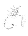
図1は本発明の医療用内視鏡1の全体の斜視図を示し、医療用内視鏡1は、操作部2と、この操作部2の先端に接続されて体内へ挿入される細長の挿入部4と、並びに前記操作部2の手元部に医療用内視鏡1の処置具11の出入りを可能にした処置具孔10と、及び光源装置15(図8)に着脱自在に接続されるコネクタ9を備えたユニバーサルコード8から構成されている。又、前記操作部2には、先端部を自在に湾曲させる湾曲操作ノブ3、及びビデオプロセッサー14(図8)をコントロールするリモートスイッチ12が設けられている。
そして挿入部4は、手元部から可とう管部5と、湾曲部6と、先端構成部7を直列に連結した構造となっている。
FIG. 1 shows an overall perspective view of a
The
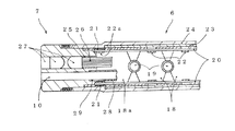
図2の湾曲部6は、短円筒状の湾曲駒18を複数個直列に並べてリベット19を介して回動自在に連結し、かつ各湾曲駒18はリベット19の軸方向と概ね直交する部位の短円筒状の軸方向の中間部位で内側へ円弧上に切り曲げて一対のロープ受け22を形成する。 そして湾曲操作ロープ20は、複数の湾曲駒18の内側のロープ受け22内を貫挿し、最先端の先端湾曲駒18aと、先端ロープ受け22aにて接合部材21を用いて接合されている。
そして、湾曲操作ロープ20の手元部は、図1に示した操作部2の湾曲操作ノブ3まで挿入部4、及び操作部2内を貫挿して湾曲操作ノブ3と連動させ、この湾曲操作ノブ3を回動操作することにより湾曲操作ロープ20を押し引き等、牽引操作させて湾曲部6を、図2において上下方向へ湾曲操作が可能な構造となっている。尚、前記図2の上下一対のロープ受け22と図2の手前・奥方向で直交する方向にもう一対のロープ受けを配設(図示せず)すると、図2の上下方向と手前奥の四方向に湾曲操作が可能な構造となる。かかる構造を用いてもよい。
そして又、湾曲駒18の外周には線材を編組したブレード23と、その外周には合成樹脂から成る外層チューブ24を被覆した構成から成っている。
The bending portion 6 in FIG. 2 has a plurality of short
The proximal portion of the bending
The outer periphery of the bending
そして先端構成部7は、口金管25内にイメージガイドファイバー26が挿入され、その先端側に対物レンズ27が配設されている。そして接続パイプ29と接続したチャンネルチューブ28は操作部2の手元部まで通ずる処置具孔10と連結しており、このチャンネルチューブ28内へ生検鉗子等の鉗子類の他に、高周波スネア、回転クリップ装置、注射針等の種々の医療用内視鏡1の処置具11が出入りでき、病変部の治療行為ができる構造となっている。
In the distal
図3は、最先端の先端湾曲駒18aと湾曲操作ロープ20の組付図を示し、先端湾曲駒18aの短円筒状の長軸方向の略中間部位で内側へ円弧状に切り曲げて、突起状の一対の先端ロープ受け22a内に湾曲操作ロープ20が貫挿され、先端ロープ受け22aで接合部材21を用いて湾曲操作ロープ20の先端部20aが接合されている。
FIG. 3 shows an assembly diagram of the most advanced tip bending piece 18a and the bending
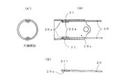
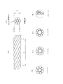
そして図5(A)は、本発明の医療用内視鏡に用いる湾曲操作ロープ20の撚り構成図、実施例1の湾曲操作ロープ200を示す。本発明の実施例の湾曲操作ロープ20は、素線直径が0.008mmから0.200mmの金属素線を複数本用いて撚合構成し、実施例1の湾曲操作ロープ200では、素線直径(線径)が0.13mmの金属素線1本の芯材200Aと、素線直径(線径)が0.11mmの金属素線6本から成る側材200Bを、芯材200Aの外側に側材200Bを撚合させ、撚合方向が長手方向に対して連続して一方向螺旋状の巻回形成とした撚合構成とし、つまり一般にスパイラルロープの撚り構成1×7(芯材1本の外側に6本の側材)とし、撚合後のロープ外径Dは0.35mmで、ロープピッチ(図示P)はロープ外径Dの2.5倍から15倍とする。ここで、スパイラルロープとは、3本以上の金属素線を撚り合わせてストランド(束)としたロープのことをいい、(1×n)の形の呼び名とし、nは金属素線の本数を示す。
FIG. 5A shows a twist configuration diagram of the bending
そして湾曲操作ロープ200の芯材200Aは、線径が0.46mmの固溶化処理したオーステナイト系ステンレス鋼線を複数のダイスを用いて線径が0.13mmになるまで伸線加工を行い、伸線加工の加工硬化により引張破断強度を約70kgf/mm2 から232kgf/mm2 まで向上させる。
このときの減面率は92.0%となる。又、側材200Bについても概ね前記芯材200Aと同様である。
Then, the core material 200A of the bending
The area reduction rate at this time is 92.0%. Further, the side material 200B is substantially the same as the core material 200A.
そして又、本実施例2の湾曲操作ロープ201の芯材201Aは、線径が0.76mmの固溶化処理したオーステナイト系ステンレス鋼線を複数のダイスを用いて線径が0.23mmになるまで一次伸線加工を行い、その後450℃で30分の一次低温熱処理を加えた後に、線径が0.168mmまで二次伸線加工を行い、その後前記同様二次低温熱処理(450℃で30分)を加えた後に、線径が0.13mmまで三次伸線加工を行うと総減面率が97.1%となって、より高い引張破断強度を有する芯材201Aを得ることができる。又、側材201Bについても概ね前記芯材201Aと同様である。 In addition, the core material 201A of the bending operation rope 201 according to the second embodiment is obtained by using a plurality of dies for the wire diameter of 0.23 mm using a solid solution treated austenitic stainless steel wire having a wire diameter of 0.76 mm. After performing the primary wire drawing and then performing the primary low temperature heat treatment at 450 ° C. for 30 minutes, the secondary wire drawing is performed until the wire diameter is 0.168 mm, and then the secondary low temperature heat treatment (at 450 ° C. for 30 minutes). ) Is added and then the third wire drawing is performed to a wire diameter of 0.13 mm, the total area reduction rate becomes 97.1%, and the core material 201A having higher tensile breaking strength can be obtained. The side material 201B is substantially the same as the core material 201A.
そして前記実施例2と同様の製造方法にて総減面率99.5%とする芯材202A、及び側材202Bから成る湾曲操作ロープ202を実施例3とし、実施例1〜3の芯材、及び 側材の製造工程を整理すると表1、2となる。尚、実施例1〜2の芯材、及び側材の金属素線の材質は、オーステナイト系ステンレス鋼線のSUS304材を用い、又実施例3の芯材、及び側材の金属素線の材質は、再溶解材のSUS316材を用いた。又、ここでいう総減面率とは、固溶化処理した線材の線径と伸線加工により伸線工程での最終仕上がり線径との間の断面積差を減少率で表したものをいい、又引張破断強度とは、線材に引張力を加えて破断したときの値を線材の断面積で除した値のことをいう。 The bending operation rope 202 made up of the core material 202A and the side material 202B having a total area reduction rate of 99.5% by the same manufacturing method as in the second embodiment is taken as the third embodiment, and the core materials of the first to third embodiments. Tables 1 and 2 summarize the manufacturing process of side materials. In addition, the material of the core material of Examples 1-2 and the metal strand of a side material uses the SUS304 material of an austenitic stainless steel wire, and the material of the core material of Example 3 and the metal strand of a side material Used a SUS316 remelting material. In addition, the total area reduction rate referred to here is a value obtained by expressing the difference in cross-sectional area between the wire diameter of the solidified wire and the final finished wire diameter in the wire drawing process as a reduction rate. Further, the tensile breaking strength means a value obtained by dividing a value obtained by applying a tensile force to the wire and breaking it by the cross-sectional area of the wire.

表1、2によれば、芯材、及び側材のいずれも総減面率は80%以上で、99.5%の実施例3において最も高い引張破断強度を示す。
そして本発明の湾曲操作ロープに用いる金属素線の芯材、及び側材は、固溶化処理したオーステナイト系ステンレス鋼線を用いて総減面率が80%から99.5%の伸線加工を行ったことを特徴とする。尚、総減面率が95%以上の強加工伸線においては後述する再溶解材を用いることが望ましい。又、総減面率が80%以上としたのは、80%を境にして引張破断強度が増大する変曲ポイントとなるからである。(図6、ばね第3版丸善株式会社63頁、図2.82参照)
そして、総減面率90%を境にして、さらに急激に引張破断強度が増大する変曲ポイントを見出した。
According to Tables 1 and 2, both the core material and the side material have a total area reduction of 80% or more, and show the highest tensile breaking strength in Example 3 of 99.5%.
And the core material of the metal strand used for the bending operation rope of the present invention, and the side material are drawn to a total area reduction of 80% to 99.5% using a solution-treated austenitic stainless steel wire. It is characterized by having gone. It should be noted that it is desirable to use a remelting material, which will be described later, in the strong work drawing with a total area reduction of 95% or more. The reason why the total area reduction is 80% or more is that it becomes an inflection point where the tensile strength at break increases from 80%. (Refer to Fig. 6, Spring 3rd edition Maruzen Co., Ltd., p. 63, Fig. 2.82)
Then, an inflection point was found at which the tensile strength at breakage increased more rapidly with the total area reduction rate of 90% as a boundary.
表3は前記実施例1又は2と同様の製造方法を用いて総減面率のみ異ならせて温度を450℃加えた後の引張破断強度の比較を示したものである。尚、表中の増加比とは、総減面率が70%のときの最大引張破断強度の値を基準としたときの比を示す。例えば総減面率が90%のとき増加比は1.31(256/196)となる。 Table 3 shows a comparison of the tensile strength at break after adding a temperature of 450 ° C. using only the manufacturing method similar to that of Example 1 or 2 while changing the total area reduction rate. The increase ratio in the table indicates the ratio based on the value of the maximum tensile breaking strength when the total area reduction is 70%. For example, when the total area reduction is 90%, the increase ratio is 1.31 (256/196).
表3によれば、総減面率80%のときには、総減面率が70%のときの値の1.12倍増加し、さらに総減面率が90%のときには1.31倍となって、明らかに総減面率が80%で引張破断強度が増大する変曲ポイントがみられ、さらに総減面率が90%で急激に引張破断強度が増大する変曲ポイントがみられ、図6に示すような非線形特性を示すと考えられる。
この理由は、総減面率80%以上という強加工による伸線加工により加工度の増大に伴い繊維状組織が現れ、そしてさらに総減面率90%以上においては、この繊維状組織が著しく発達したことによると考えられる。
そして総減面率が99.5%以下としたのは、これを超える伸線加工の強い加工度では、後述する再溶解材を用いても組織内に空隙が生じはじめて脆化し、又伸びの不足により、特に撚合構成時に側材の金属素線の断線が発生し易くなり、これが伸線加工、撚線加工の限界と考えるからである。
従って、後述する接合部材21の共晶合金を用いて溶融熱により湾曲操作ロープに用いて金属素線の引張破断強度を向上させながら接合させる為には、総減面率が80%から99.5%以下が好ましく、より好ましくは、総減面率が90%から99.5%であり、より高い引張破断強度を得て安定して撚合構成する為には、総減面率が90%から99%である。
According to Table 3, when the total area reduction rate is 80%, it increases 1.12 times the value when the total area reduction rate is 70%, and when the total area reduction rate is 90%, it becomes 1.31 times. Clearly, an inflection point at which the tensile strength at break is increased when the total area reduction is 80%, and an inflection point at which the tensile elongation at break is increased at 90% is shown in FIG. It is considered that the nonlinear characteristic as shown in FIG.
The reason for this is that a fibrous structure appears as the degree of processing increases due to wire drawing by strong processing with a total area reduction rate of 80% or more, and when the total area reduction rate is 90% or more, this fibrous structure develops remarkably. This is probably due to the fact that
The reason why the total area reduction is 99.5% or less is that, when the degree of workability is higher than this, even if a remelting material described later is used, voids begin to form in the structure and become brittle, This is because, due to the shortage, breakage of the metal wire of the side material is likely to occur particularly in the twisted configuration, which is considered as the limit of wire drawing and twisting.
Therefore, in order to join the eutectic alloy of the joining
そして「固溶化処理したオーステナイト系ステンレス鋼線の伸線加工」としたのは、加工性のよいオーステナイト組織を得る為であり、オーステナイト系ステンレス鋼線は変態点を利用した熱処理による結晶粒の微細化ができず、冷間加工によってのみ結晶粒の微細化が可能で、伸線加工により顕著な加工硬化性を示して引張破断強度を向上させることができるからである。又オーステナイト系ステンレス鋼線を用いる理由は、マルテンサイト系ステンレス鋼線では熱処理による焼入硬化性を示して熱影響を受け易く、又フェライト系ステンレス鋼線では温度脆性(シグマ脆性)の問題があるからである。 The reason why “Solution-treated austenitic stainless steel wire was drawn” was to obtain an austenitic structure with good workability, and the austenitic stainless steel wire was refined by heat treatment using transformation points. This is because the crystal grains can be refined only by cold working, and the tensile breaking strength can be improved by exhibiting remarkable work hardenability by wire drawing. The reason for using austenitic stainless steel wire is that martensitic stainless steel wire is hardened by heat treatment and is susceptible to heat, and ferritic stainless steel wire has a problem of temperature brittleness (sigma brittleness). Because.
次に図3において湾曲操作ロープ20の先端部20aと、先端湾曲駒18aの先端ロープ受け22aとは、接合部材21を溶融加熱して接合させる。
そして接合部材21は、溶融温度が180℃から495℃の共晶合金、又は湾曲操作ロープ20の金属素線が後述するMoを含むオーステナイト系ステンレス鋼線のときには180℃から525℃の共晶合金を用いる。ここでいう共晶合金とは、合金の成分比を変更することにより得られる最低融点(溶融温度)を有する特殊な合金のことをいい、具体的には、金又は銀を含む合金材で金錫系合金材として金80重量%、残部が錫で溶融温度が280℃、又銀錫系合金として銀3.5重量%、残部が錫で溶融温度が221℃、そして、金88重量%、残部がゲルマニウムで溶融温度が356℃、又銀と錫とインジウムから成り、溶融温度が450℃から472℃の共晶合金であり、その代表例を表4に示す。
Next, in FIG. 3, the distal end portion 20 a of the bending
The joining
ここで接合部材21として金を用いる理由は、耐食性、展延性向上の為であり、銀を用いる理由は、融点調整等の為であり、錫を用いる理由は、融点を低下させて湾曲操作ロープ20との濡れ性を向上させる為であり、又インジウム、銅を用いる理由も濡れ性向上の為であり、そしてゲルマニウムを用いる理由は、金属間化合物の結晶粒粗大化を抑止して、接合強度の低下防止を図る為である。尚、鉛、アンチモンは人体への不適合性、又加工性の難度等の観点から好ましくない。
Here, the reason why gold is used as the joining
そして接合部材21の溶融温度が180℃から495℃、又は180℃から525℃としたのは、180℃を下回ると加工硬化させた湾曲操作ロープ20の引張破断力を接合部材21の溶融温度を利用して向上させることはできず、そして495℃を超えると湾曲操作ロープ20に用いる金属素線のオーステナイト系ステンレス鋼線の特質から、又は525℃を超えるとMoを含むオーステナイト系ステンレス鋼線の特質から、前記各オーステナイト系ステンレス鋼線を520℃、又は540℃を超える800℃に加熱すると鋭敏化現象を生じて、後述するように極端に引張破断強度特性等を低下させることとなり、この現象を防ぎ、湾曲操作ロープ20の機械的強度特性を最大限に発揮させる為である。
The reason why the melting temperature of the joining
この構造により、以下に述べる特有の作用効果がある。
湾曲操作ロープ20と先端湾曲駒18aの先端ロープ受け22aとを前記接合部材21である共晶合金を用いて接合すると、接合時の溶融熱によって湾曲操作ロープ20の芯材、及び側材のような細線を撚合構成したロープであっても引張強度特性等を低下させることなく、むしろこの引張破断強度特性等を向上させて強固接合させることができる。
This structure has the following specific effects.
When the bending
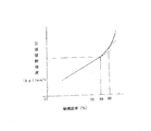
そして図7は、一般に金属素線の母線にオーステナイト系ステンレス鋼線を用いて総減面率が95%以上の最終伸線加工後の金属素線を熱影響下(各温度30分)での引張破断強度特性を示した図で、SUS304材のときは図示イを、SUS316材のときは図示ロを示す。
これによるとSUS304材は180℃の熱影響により引張破断強度が上昇し始め、概ね450℃近傍で最高の引張破断強度特性を示し、495℃まで引張破断強度特性向上効果が顕著にみられ、そして520℃を超えると常温(20℃)よりも急激に引張破断強度が低下する。又、Moを含むSUS316材は、低温側でSUS304材と同様な傾向を示すが高温側では概ね480℃近傍で最高の引張破断強度特性を示し、525℃まで引張破断強度特性向上効果が顕著にみられ、そして540℃を超えると常温(20℃)よりも急激に引張破断強度が低下する。
この引張破断強度特性が急激に低下する理由は、前述のように、この固溶化処理したオーステナイト系ステンレス鋼線は、前記520℃、540℃を超える温度から800℃に加熱されると、カーボンの析出、クロムの移動の為のエネルギーを必要とし、鋭敏化現象を生じて、特にカーボンが0.08%以下の通常のSUS304のオーステナイト系ステンレス鋼線では、700℃4分から5分程度で、この鋭敏化現象が現れ、引張破断強度が極端に低下するからである。
FIG. 7 shows that, in general, an austenitic stainless steel wire is used as the bus bar of the metal wire, and the metal wire after the final wire drawing with a total area reduction of 95% or more is subjected to heat (each temperature is 30 minutes). The drawing shows the tensile strength at break. In the case of SUS304 material, the illustrated a is shown, and in the case of SUS316 material, the illustrated b is shown.
According to this, SUS304 material began to increase in tensile strength at 180 ° C due to the heat effect, showed the highest tensile strength at about 450 ° C, and the effect of improving tensile strength at 495 ° C was noticeable. If it exceeds 520 ° C., the tensile strength at break will decrease more rapidly than normal temperature (20 ° C.). The SUS316 material containing Mo shows the same tendency as the SUS304 material on the low temperature side, but shows the highest tensile rupture strength characteristics at about 480 ° C. on the high temperature side, and the effect of improving the tensile rupture strength properties to 525 ° C. is remarkable. In addition, when the temperature exceeds 540 ° C., the tensile strength at break decreases more rapidly than normal temperature (20 ° C.).
The reason why the tensile strength at break is abruptly decreased is that, as described above, when the austenitic stainless steel wire subjected to the solution treatment is heated from 800 ° C. to 800 ° C., the carbon This requires energy for precipitation and migration of chromium, causing a sensitization phenomenon. In particular, in an ordinary SUS304 austenitic stainless steel wire having a carbon content of 0.08% or less, the temperature is about 700 ° C. for about 4 to 5 minutes. This is because a sensitization phenomenon appears and the tensile strength at break is extremely reduced.
このような引張破断強度特性を有する為、SUS304材の金属素線の低温熱処理温度範囲は180℃から495℃が望ましく、又Moを含む例えばSUS316材(Moが2重量%〜3重量%)の金属素線の低温熱処理温度範囲は180℃から525℃が望ましい。
従って、接合部材21の溶融温度は、前記望ましい低温熱処理温度範囲と一致させる。 このように本発明は、強加工伸線して総減面率の高いオーステナイト系ステンレス鋼線の温度による引張破断強度特性に着目して、並びに、湾曲操作ロープ20に用いる金属素線は細線・極細線で熱容量小で熱影響を受け易いことに着目して、湾曲操作ロープの金属素線の撚合状態での引張破断強度を、接合部材21の溶融熱を利用して大幅に向上させながら、かつ接合することのできる、新たな技術思想を提供するものである。
In order to have such tensile breaking strength characteristics, the low temperature heat treatment temperature range of the SUS304 metal strand is preferably 180 ° C. to 495 ° C., and for example, SUS316 material containing Mo (Mo is 2 wt% to 3 wt%). The low temperature heat treatment temperature range of the metal wire is desirably 180 ° C. to 525 ° C.
Therefore, the melting temperature of the joining
そして、本実施例に用いる金属素線のオーステナイト系ステンレス鋼線の化学成分は、重量%でC:0.15%以下、Si:1%以下、Mn:2%以下、Ni:6%〜16%、Cr:16%〜20%、P:0.045%以下、S:0.030%以下、Mo:3%以下、残部が鉄及び不可避的不純物から成る。このように高珪素ステンレス鋼(Si:3.0%〜5.0%)を用いなくても前記工法を用いることにより、高強度のオーステナイト系ステンレス鋼線の金属素線を得ることができる。尚、Cは引張破断強度向上の為には、0.005%以上が望ましく、粒界腐食抑制の観点から0.15%以下が望ましい。 And the chemical component of the austenitic stainless steel wire of the metal strand used for a present Example is C: 0.15% or less, Si: 1% or less, Mn: 2% or less, Ni: 6% -16 in weight%. %, Cr: 16% to 20%, P: 0.045% or less, S: 0.030% or less, Mo: 3% or less, the balance being iron and inevitable impurities. Thus, even if it does not use high silicon stainless steel (Si: 3.0%-5.0%), the metal strand of a high-strength austenitic stainless steel wire can be obtained by using the said construction method. C is preferably 0.005% or more for improving the tensile strength at break, and is preferably 0.15% or less from the viewpoint of suppressing intergranular corrosion.
本発明の医療用内視鏡の湾曲操作ロープ20に用いる芯材、又は側材の金属素線は、素線直径が0.008mmから0.200mmのオーステナイト系ステンレス鋼線で、特に引張破断強度が300kgf/mm2 以上で、総減面率が95%以上の伸線加工を可能とする為には、再溶解材を用いたSUS304材、又はSUS316材が望ましい。
この理由は、ステンレス鋼線の伸線時の断線原因は、表面疵もさることながら酸化物系介在物であることが最も多く、細線・極細線化するほどこの傾向が著しい。
そしてその化学成分は、介在物生成元素であるAl、Ti、Ca、Oの成分は低く、又硫化物の作用で伸線低下を引き起こすSも低く抑える。具体的なオーステナイト系ステンレス鋼線の化学成分は、重量%で、C:0.08%以下、Si:0.10%以下、Mn:2%以下、P:0.045%以下、S:0.010%以下、Ni:8%〜12%、Cr:16%〜20%、Mo:3%以下、Al:0.0020%以下、Ti:0.10%以下、Ca:0.005%以下、O:0.0020%以下、で残部がFeと不可避的不純物から成る。
そして再溶解材の製造方法としては、ステンレス鋼の溶製後のインゴットにフラックスを用いたエレクトロスラグ再溶解の製造方法等である。
The core or side metal wire used in the bending
The reason for this is that the cause of disconnection when drawing a stainless steel wire is most often oxide inclusions as well as surface flaws, and this tendency becomes more prominent as the wire becomes finer and finer.
And the chemical component is low in the components of Al, Ti, Ca and O which are inclusion generating elements, and also suppresses S which causes a decrease in wire drawing due to the action of sulfide. The specific chemical components of the austenitic stainless steel wire are, by weight, C: 0.08% or less, Si: 0.10% or less, Mn: 2% or less, P: 0.045% or less, S: 0 0.010% or less, Ni: 8% to 12%, Cr: 16% to 20%, Mo: 3% or less, Al: 0.0020% or less, Ti: 0.10% or less, Ca: 0.005% or less , O: 0.0020% or less, with the balance being Fe and inevitable impurities.
And as a manufacturing method of a remelting material, it is the manufacturing method etc. of the electroslag remelting which used the flux for the ingot after melting of stainless steel.
そして次に、実施例1〜3の湾曲操作ロープ200〜202と湾曲駒とを接合部材21を用いて接合する際に接合部材21の溶融加熱時間、及び組付時間等を考慮して、温度と引張破断力との関係を表5に示す。尚、時間の5秒は、接合部材21を用いて接合固着するときにロープが180℃以上で溶融加熱される平均時間を示し、又60秒は、再度接合固着作業(やり直し作業)によりロープが180℃以上で再溶融加熱されるのを含む時間を示す。又ここでロープの引張破断力とは、ロープに引張力を加えてロープが破断したときの最大荷重のことをいう。
Then, when the bending
表5によれば、接合部材21の溶融加熱時間を考慮して450℃で5秒間の加熱であっても、湾曲操作ロープ200の引張破断力は16.5kgfから17.1kgfとなって約3.6%増大し、又湾曲操作ロープ201の引張破断力は24.7kgfから25.9kgfとなって約4.9%増大し、さらに湾曲操作ロープ202の引張破断力は25.6kgfから27.0kgfとなって約5.5%増大し、総減面率の増加とともに引張破断力の増加率は増大する傾向となる。
そして前述のように、接合部材21の共晶合金を用いて溶融熱により湾曲操作ロープの引張破断力を向上させながら接合させる為には、湾曲操作ロープに用いる金属素線の総減面率は80%から99.5%が望ましく、好ましくは90%から99.5%以下で、高い引張破断力を有する湾曲操作ロープを安定して得る為には、90%以上99%以下が望ましい。この理由は、99.5%以上の総減面率を有する金属素線は伸びが不足して撚合時に、側線に用いる金属素線の断線が発生し易いからである。
According to Table 5, the
As described above, in order to join the eutectic alloy of the joining
そして湾曲操作ロープの他の実施例を図5(B)〜(E)に示す。図5(B)〜(E)はそれぞれ実施例4〜7を示し、スパイラルロープの撚り構成は、それぞれ1×8、1×9、1×10、1×19である。
そして、芯材と側材の金属素線の素線直径は、いずれも0.008mmから0.200mmとし、芯材と側材とは同一素線直径の金属素線を撚合構成して用いてもよい。尚、実施例4〜6、及び撚り構成1×7の他の実施例の芯材と側材の素線直径(線径)、及び線径比(芯材/側材)を整理すると、表6となる。
Another embodiment of the bending operation rope is shown in FIGS. FIGS. 5B to 5E show Examples 4 to 7, respectively, and the twisted configuration of the spiral rope is 1 × 8, 1 × 9, 1 × 10, and 1 × 19, respectively.
The core diameters of the metal wires of the core material and the side material are both 0.008 mm to 0.200 mm, and the core material and the side material are formed by twisting and forming metal wires having the same wire diameter. May be. In addition, when arranging the wire diameter (wire diameter) and the wire diameter ratio (core material / side material) of the core material and side material of Examples 4 to 6 and other examples of the
表6によれば、例えば実施例6(図示(D))は、撚り構成1×10で、芯材は線径が0.18mmの金属素線1本と、側材は線径が0.085mmの金属素線9本からなり、線径比は2.12である。同様に、撚り構成1×7の他の実施例において、芯材は線径が0.122mm、側材の線径は0.114mmで線径比は1.07である。
そして、前記各実施例で示すように、芯材の線径は側材の線径よりも1.07倍から2.12倍の太径線を用いている。芯材も側材も同一線径を用いてもよいが、芯材に太径線を用いる理由は、湾曲操作ロープ20に引張力を加えたとき、芯材1本に加わる引張力の負荷は、数本から成る側材よりもその構造差(側材はスパイラル状で伸び易い構造に対して、芯材はストレート状で直接引張力の負荷が加わり易い構造)から増大する。この為、芯材に太径線を用いて横断面積を増大させて芯材へ加わる引張応力を軽減させて、その結果芯材の側材よりも早い破断を防いで、ロープとしての引張破断力を向上させる為である。
そして芯材と側材とが同一線径の線径比1.0を下回れば、芯材へ加わる引張力の負荷は増大して芯材の早期破断によるロープの引張破断力を低下させる。又、前記上限値(線径比2.12)を上回れば、芯材の剛性が増大して、耐繰り返し曲げ疲労特性が劣ってくる。尚補足すれば、前記実施例1 〜3 の線径比は、1.18である。
従って、線径比(芯材/側材)は、1.0倍から2.12倍が好ましく、より好ましくは1.07倍から2.12倍で、さらに好ましくは、1.18倍から2.12倍である。
According to Table 6, for example, Example 6 (illustration (D)) has a twist configuration of 1 × 10, the core material is one metal strand having a wire diameter of 0.18 mm, and the side material has a wire diameter of 0.1. It consists of nine 085 mm metal strands and the wire diameter ratio is 2.12. Similarly, in another embodiment of the
And as shown in the said each Example, the wire diameter of the core material uses the large diameter wire 1.07 times to 2.12 times the wire diameter of the side material. The same wire diameter may be used for the core material and the side material, but the reason for using the thick wire for the core material is that when a tensile force is applied to the bending
And if a core material and a side material are less than the wire diameter ratio 1.0 of the same wire diameter, the load of the tensile force added to a core material will increase, and the tensile fracture force of the rope by the early fracture | rupture of a core material will be reduced. Moreover, if it exceeds the said upper limit (wire diameter ratio 2.12), the rigidity of a core material will increase and a repeated bending fatigue-proof characteristic will be inferior. If supplemented, the wire diameter ratio of Examples 1 to 3 is 1.18.
Therefore, the wire diameter ratio (core material / side material) is preferably 1.0 times to 2.12 times, more preferably 1.07 times to 2.12 times, and still more preferably 1.18 times to 2. .12 times.
そして補足すれば、湾曲操作ロープ20は、芯材、及び側材を一定の撚りピッチで撚合構成した後に短時間低温熱処理(380℃から550℃で2秒から10秒)を加えた後、又は撚合構成した後に公知の曲げと捩りの歪を与えるスピナー矯正機、又はローラーレベラー式矯正機等により矯正加工した後に短時間低温熱処理(380℃から550℃で2秒から10秒)を加えた後に、前記接合部材21を用いて接合せても同様の効果を得ることができる。
そして前記工法を用いることにより、湾曲操作ロープの直線性を向上させることができ、術者の医療用内視鏡の操作性をより向上させることがでる。この理由は、撚合加工後、又は矯正加工後の前記短時間熱処理により、湾曲操作ロープに局部的に発生した集中応力を平均化させることによる、と考えることができる。
And, supplementally, the bending
And by using the said construction method, the linearity of a bending operation rope can be improved and the operativity of a medical endoscope of an operator can be improved more. This reason can be considered to be because the concentrated stress generated locally on the bending operation rope is averaged by the short-time heat treatment after twisting or straightening.
そして、この固溶化処理したオーステナイト系ステンレス鋼線を用いて強加工の伸線加工をして引張破断強度特性を向上させた芯材と側材を撚合構成した湾曲操作ロープ20との接合部材21は、湾曲操作ロープ20の引張破断強度向上効果が顕著にみられる温度範囲と同じ温度の、180℃から495℃の溶融温度をもつ共晶合金、又は、湾曲操作ロープの金属素線がMoを含むオーステナイト系ステンレス鋼線のときには180℃から525℃の溶融温度をもつ共晶合金を用いる。
これにより共晶合金の溶融熱を利用して引張破断強度を向上させながら接合することが可能となる。尚、接合部材21の溶融温度が180℃から495℃、又は180℃から525℃としたのは、この範囲であれば溶融熱を利用して湾曲操作ロープの引張破断強度を向上させて、湾曲駒18と湾曲操作ロープ20との強固接合が可能となるからである。
And the joining member of the bending
As a result, it is possible to perform the joining while improving the tensile strength at break using the melting heat of the eutectic alloy. Note that the melting temperature of the joining
そして、接合部材21の溶融熱により先端ロープ受け22aとの接合部の湾曲操作ロープ20の先端部20aの引張破断強度は増大し、この引張破断強度増大に伴い、接合部での湾曲操作ロープの耐繰り返し曲げ疲労特性は向上し、術者の操作中の、湾曲操作ロープ20の先端部20aの接合部へ加わる繰り返し曲げ疲労により、湾曲操作ロープ20と先端ロープ受け22aとが離脱する危険は生じない。
尚、補足すれば、溶融温度が605℃から800℃の銀ろう、溶融温度が895℃から1030℃金ろうを用いた場合には、前述したように芯材、又は側材の鋭敏化現象による脆化、又は、なまし状態となって大幅に引張破断強度が低下し、引張破断強度及び曲げ応力の低下に伴い、湾曲操作ロープ20の先端部20aが先端ロープ受け22aからの脱落の危険が増大し、湾曲操作ノブ3の操作不能を生じ、医療用内視鏡が操作不能に陥る恐れがある。
そして、溶融温度が約880℃の金74.5重量%から75.5重量%、銀12重量%から13重量%、その他亜鉛、鉄、鉛等0.15重量%以下の金ろうを用いた場合、又溶融温度が780℃の銀72重量%、銅28重量%の銀ろうを用いた場合にも、前記同様の問題が発生し易い。
Then, the tensile breaking strength of the distal end portion 20a of the bending
In addition, if a silver solder having a melting temperature of 605 ° C. to 800 ° C. and a gold solder having a melting temperature of 895 ° C. to 1030 ° C. are used, as described above, the core material or the side material may be sensitized. The tensile breaking strength is greatly reduced due to embrittlement or annealing, and the tip 20a of the bending
Then, a gold solder having a melting temperature of about 880 ° C. and having a gold content of 74.5 wt. In this case, the same problem as described above is likely to occur when a silver solder having a melting temperature of 780 ° C. of 72% by weight of silver and 28% by weight of copper is used.
そして次に、湾曲操作ロープ20の先端部20aの部分には、ロープ受け22aの長手方向の長さに添って所定長、例えばロープ受け22aの長手方向の長さが2mmであれば、2mmから100mm程度電解研磨を施すことが望ましい。又は、紙やすり等により研磨してもよい。
そして、湾曲操作ロープ20の先端部20aを、接合部材21の共晶合金を溶融する前に研磨する理由は、特に強加工における伸線加工(総減面率90%以上)した金属素線を用いて撚合構成した湾曲操作ロープは、その接合部材21との濡れ性が極端に悪くなり、これを防ぐ為に電解研磨等を用いて酸化皮膜を除去して濡れ性を向上させ、接合部材21による接合性を向上させる為である。又、予め全長にわたって電解研磨等を施した湾曲操作ロープ20を用いてもよい。尚、補足すれば、前記湾曲操作ロープの接合部材21との濡れ性が極端に悪くなる理由は、強加工伸線加工の加工度の増大に伴って現われる金属素線表層部の繊維状組織に発達、及び酸化被膜の形成によるものと考えることができる。
Then, the tip portion 20a of the bending
The reason for polishing the distal end portion 20a of the bending
そして又、湾曲操作ロープ20の先端部20aの部分には、ロープ受け22aの長手方向の長さに添って所定長、例えばロープ受け22aの長手方向の長さが2mmであれば、1mmから10mm程度めっき処理、又は接合部材211を芯材と側材との線間間隙に含浸、及び側材の外周に固着させて、その後接合部材21を溶融固着させてもよい。かかる場合、めっき処理に用いる材料は、前記接合部材21の共晶合金と同一、又は同種の組成成分を含む材料を用いることが望ましく、例えば接合部材21に金、又は錫を含む成分が含まれていれば、めっき処理する材料は、金めっき、又は錫めっきが望ましい。
そして湾曲操作ロープ20の先端部20aの部分に予め含浸・固着させる接合部材211は、接合部材21と同一又は同種の共晶合金が望ましい。尚、ここでいう同種の共晶合金である接合部材とは、金、銀、又は錫のうちいずれか一つ、又は二つの成分の合計した重量%が全体の50重量%以上のものをいい、例えば表1で符号A1からA5の間、又はB1からB5との間では同種であり、符号A1からA5とB1からB5との間のいずれかの組み合わせは異種である。
In addition, if the length of the rope receiver 22a is 2 mm in the longitudinal direction of the rope receiver 22a, for example, if the length of the rope receiver 22a in the longitudinal direction is 2 mm, the tip portion 20a of the bending
The joining member 211 to be impregnated and fixed in advance on the tip 20a of the bending
この構造により、以下に述べる特有の作用効果がある。つまり、湾曲操作ロープ20の先端部20aと先端のロープ受け22aとの接合を強固にさせ、又接合部材211と接合部材21との接合部での溶融一体化固着により、接合強度を大幅に向上させることができる。
そして、湾曲操作ロープ20の先端部20aをめっき処理、又は接合部材211を予め含浸・固着する理由は、前記強加工による伸線加工により濡れ性が極端に悪化した湾曲操作ロープ20の接合部材21との濡れ性を向上させて強固結合を可能とする為である。尚、予め接合部材211を溶融固着した場合には、ロープ受け22aに貫挿後、溶融固着した接合部材211にレーザー光を照射させて接合部材211を再溶融させてロープ受け22aと接合させてもよい。かかる場合、接合部材211は、湾曲操作ロープ20の先端部20aの表面に撚合構成の撚り線の谷間が目視できない程度に厚く形成する必要があり、又本発明の湾曲操作ロープ20の各実施例で用いる接合部材21と同一、又は同種の共晶合金を用いることが望ましい。これにより、接合工程での先端ロープ受け22aと湾曲操作ロープ20の先端部20aとの接合の組付作業を簡略化することができる。
This structure has the following specific effects. In other words, the bonding strength is greatly improved by strengthening the bonding between the distal end portion 20a of the bending
The reason why the distal end portion 20a of the bending
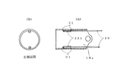
そして次に、湾曲操作ロープ20の先端ロープ受け22aの構造は、先端湾曲駒18aの内周側先端部へ短小管体の管体ロープ受け221を用いて固着させ、湾曲操作ロープ20の先端部20aを貫挿させた後、接合部材21を用いて接合させてもよい。かかる場合、先端湾曲駒18aのロープ受け22a、又は管体ロープ受け221は、湾曲操作ロープ20と同一、又は同種の材料から形成されることが接合強度向上の観点からより望ましい。ここで同種材料とは、オーステナイト系かマルテンサイト系か否かを問わず、ステンレス鋼材であれば同種のことをいい、従ってアルミニウム材とは異種材料を意味する。最も好ましいのは、同一材料である。
Then, the structure of the distal end rope receiver 22a of the bending
そして次に、本発明の医療用内視鏡の製造方法について以下に述べる。
先端部に湾曲駒が複数個連結して成る湾曲部を設けて、前記湾曲駒と湾曲操作ロープの先端部とを接合部材を用いて接合し、前記湾曲部を牽引操作する前記湾曲操作ロープから成る医療用内視鏡の製造方法において、前記湾曲操作ロープは、固溶化処理したオーステナイト系ステンレス鋼線を用いて、総減面率が90%から99.5%の伸線加工した金属素線を用いて複数本撚合構成したロープから成る工程と、前記撚合構成したロープを電解研磨した後に所定長切断する工程と、又は前記撚合構成したロープを所定長切断した後に電解研磨する工程と、その後切断した湾曲操作ロープの先端部を前記湾曲駒と接触させて、180℃から495℃の溶融温度をもつ共晶合金から成る前記接合部材を溶融させ、又は前記操作用ロープの金属素線がMoを含むオーステナイト系ステンレス鋼線のときには、180℃から525℃の溶融温度をもつ共晶合金からなる前記接合部材を溶融させ、前記湾曲駒と前記操作用ロープとを前記接合部材により接合する工程からなることを特徴とする医療用内視鏡の製造方法である。
この構成により、強加工伸線した金属素線を複数本用いて撚合構成して湾曲操作ロープを形成し、又強加工の伸線加工による接合部材との濡れ性を向上させ、かつ湾曲駒との接合において、オーステナイト系ステンレス鋼線の強加工と低温熱処理の引張破断強度との相関性に着目して、強加工による高度の引張破断強度を有する湾曲操作ロープの引張破断強度を接合時の接合部材の溶融熱を利用して、より引張破断強度を向上させて接合できる、新たな技術思想から成る医療用内視鏡の製造ができる。
Next, a method for manufacturing the medical endoscope of the present invention will be described below.
A bending portion formed by connecting a plurality of bending pieces to the distal end portion, the bending piece and the distal end portion of the bending operation rope are joined using a joining member, and the bending operation rope that pulls the bending portion is operated. In the method for manufacturing a medical endoscope, the bending operation rope is a metal strand that has been drawn using a solidified austenitic stainless steel wire with a total area reduction of 90% to 99.5%. And a step of cutting a predetermined length after electropolishing the twisted rope, or a step of electropolishing after cutting the twisted rope by a predetermined length. Then, the tip of the bending operation rope cut thereafter is brought into contact with the bending piece to melt the joining member made of a eutectic alloy having a melting temperature of 180 ° C. to 495 ° C., or the metal element of the operation rope line In the case of an austenitic stainless steel wire containing Mo, a step of melting the joining member made of a eutectic alloy having a melting temperature of 180 ° C. to 525 ° C. and joining the bending piece and the operation rope by the joining member It is a manufacturing method of the medical endoscope characterized by comprising.
With this configuration, a bending operation rope is formed by twisting and forming a plurality of metal wires that have been subjected to strong work drawing, and the wettability with the joining member by the drawing work of strong work is improved. Focusing on the correlation between the strong working of austenitic stainless steel wire and the tensile breaking strength of low temperature heat treatment, the tensile breaking strength of the bending operation rope with high tensile breaking strength by strong working is By using the heat of fusion of the joining member, it is possible to manufacture a medical endoscope having a new technical idea that can be joined with further improved tensile fracture strength.
そして又、先端部に湾曲駒が複数個連結して成る湾曲部を設けて、前記湾曲駒と湾曲操作ロープとを接合部材を用いて接合し、前記湾曲駒を牽引操作する前記湾曲操作ロープから成る医療用内視鏡の製造方法において、前記湾曲駒はステンレス鋼材を用いて円筒状に成形して連結ピンにて連結する工程と、前記操作用ロープは、固溶化処理したオーステナイト系ステンレス鋼線を用いて、総減面率が90%から99.5%の伸線加工した金属素線を用いて複数本撚合構成したロープから成る工程と、前記撚合構成したロープを電解研磨した後に所定長切断する工程と、又は前記撚合構成したロープを所定長切断した後に電解研磨する工程と、その後切断した湾曲操作ロープの先端部を前記湾曲駒と接触させて、180℃から495℃の溶融温度をもつ共晶合金から成る前記接合部材を溶融させ、又は前記操作用ロープの金属素線がMoを含むオーステナイト系ステンレス鋼線のときには、180℃から525℃の溶融温度をもつ共晶合金からなる前記接合部材を溶融させ、同一、又は同種の材料から成る前記湾曲駒と前記操作用ロープとを前記接合部材により接合する工程からなることを特徴とする医療用内視鏡の製造方法である。
この構成により、湾曲操作ロープと湾曲駒との接合において、オーステナイト系ステンレス鋼線の強加工と低温熱処理の引張破断強度との相関性に着目して、強加工による高度の引張破断強度を有する湾曲操作ロープの引張破断強度を、接合時の接合部材の溶融熱を利用して、より引張破断強度を向上させ、さらに湾曲操作ロープと湾曲駒とが同一、又は同種材料を用いることにより湾曲操作ロープと接合部材との濡れ性、及び湾曲駒と接合部材との濡れ性を接合面で概ね均一にさせることにより、接合部の部材間の接合力を均一にさせることにより、より高い接合部の接合強度を得ることができる。
Further, a bending portion formed by connecting a plurality of bending pieces at the tip is provided, the bending piece and the bending operation rope are joined using a joining member, and the bending piece is pulled to operate the bending operation rope. In the method for manufacturing a medical endoscope, the bending piece is formed into a cylindrical shape using a stainless steel material and connected with a connecting pin, and the operation rope is a solution-treated austenitic stainless steel wire Using a wire composed of a plurality of wire strands having a total area reduction of 90% to 99.5%, and after electropolishing the twisted rope A step of cutting a predetermined length, or a step of electropolishing after cutting the twisted rope by a predetermined length, and then contacting a tip of the bending operation rope that has been cut thereafter with the bending piece; Melting temperature When the joining member made of a eutectic alloy having a melting point is melted, or when the metal wire of the operation rope is an austenitic stainless steel wire containing Mo, it is made of a eutectic alloy having a melting temperature of 180 ° C. to 525 ° C. A method for manufacturing a medical endoscope, comprising the step of melting the joining member and joining the bending piece made of the same or the same kind of material and the operating rope with the joining member.
With this configuration, in joining the bending operation rope and bending piece, paying attention to the correlation between strong processing of austenitic stainless steel wire and tensile breaking strength of low temperature heat treatment, bending with high tensile breaking strength by strong processing The tensile breaking strength of the operation rope is further improved by utilizing the heat of fusion of the joining member at the time of joining, and the bending operation rope and the bending piece are made of the same or the same kind of material by using the same or the same material. By joining the joint force between the members of the joint portion by making the wettability between the joint piece and the bending piece and the wettability of the bending piece and the joint member substantially uniform at the joint surface, the joint of the joint portion can be made higher. Strength can be obtained.
そして又、前記医療用内視鏡の製造方法の湾曲駒と湾曲操作ロープとを接合する工程が、真空環境下、又は不活性ガス環境下における接合工程から成ることがより望ましい。
この理由は、医療用内視鏡のオートクレープ滅菌後であっても、フラックス残留に起因する高強度を有する湾曲操作ロープの引張破断強度の低下を防いで接合させることができるからである。
Further, it is more desirable that the step of joining the bending piece and the bending operation rope in the method for manufacturing a medical endoscope includes a joining step in a vacuum environment or an inert gas environment.
The reason for this is that even after the autoclave sterilization of the medical endoscope, the bending operation rope having high strength due to residual flux can be joined while preventing a decrease in tensile breaking strength.
次に本発明の医療用内視鏡1の全体を示す図1において、医療用内視鏡1は、操作部2と、この操作部2の先端に接続されて体内へ挿入される細長の挿入部4と、並びに前記操作部2の手元部に医療用内視鏡の処置具11の出入りを可能にした処置具孔10が配設されている。
この処置具孔10より処置具11を出入りさせて病変部の治療行為をすることができる。ここでいう医療用内視鏡1の処置具11とは、生検鉗子等の鉗子類の他に、例えば高周波スネア、回転クリップ装置、注射針等の処置具11のことをいう。
ここで例えば高周波スネアを用いて患部治療する際、患部に生理食塩水を注射針にて注入した後病変部を切除する。その際に生理食塩水の漏れ等により、例えば銀成分を含む接合部材21を用いた場合には、生理食塩水との接触により硫化銀等が形成され黒色化が始まり、時間の経過とともに黒色化がさらに進んで腐食が増大して接合強度が低下する。
この為、腐食進行による接合強度の低下防止、及び黒色化の防止の観点から処置具11に生理食塩水を用いる場合には、金系共晶合金の接合部材21を用いることが、より望ましい接合形態である。
Next, in FIG. 1 which shows the whole of the
The treatment tool 11 can be moved in and out of the
Here, for example, when treating an affected area using a high-frequency snare, the affected area is excised after injecting physiological saline into the affected area with an injection needle. At that time, due to leakage of physiological saline or the like, for example, when the joining
For this reason, in the case of using physiological saline for the treatment instrument 11 from the viewpoint of preventing reduction in bonding strength due to progress of corrosion and preventing blackening, it is more desirable to use a
次に図8は、本発明の医療用内視鏡1を用いて術者の手技を円滑かつ迅速にする為の医療用内視鏡1と、医療用内視鏡画像処理システムを示す。
医療用内視鏡1は、ユニバーサルコード8の端部に備えた着脱自在のコネクタ9を光源装置15へ接続し、さらにビデオプロセッサー14に電気的、機械的に連結されている。 そして、ビデップロセッサー14はモニター13と連結されて医療用内視鏡1からの画像をモニター13にて表示する構成となっている。又、写真撮影装置16、及びプリンター17と電気的、機械的に連結されている。
そして高強度の引張破断強度特性を有する湾曲操作ロープ20を備えた医療用内視鏡1の湾曲操作ノブ3を操作することにより、術者の所望の位置へ湾曲部6を湾曲させて、迅速、的確、かつ安定して操作することができ、その結果前記医療用内視鏡画像処理システムによりモニターに映し出された病変部の状態を術者が正確に把握認識することができ、術者の迅速治療に大きく寄与することができる。
Next, FIG. 8 shows a
In the
Then, by operating the bending
[発明の効果]
以上説明のとおり、本発明の医療用内視鏡は、強加工伸線して引張破断強度の高い金属素線を複数本用いて撚合構成し、引張破断力の高い湾曲操作ロープを備え、そして接合部材である共晶合金の溶融熱を利用して、前記湾曲操作ロープの引張破断力をより向上させながら、湾曲駒のロープ受けとの強固な接合を可能とするものである。
[Effect of the invention]
As described above, the medical endoscope of the present invention is formed by twisting a plurality of metal strands having high tensile strength and tensile strength, and includes a bending operation rope having high tensile strength. Then, using the heat of fusion of the eutectic alloy that is the joining member, the bending operation rope can be firmly joined to the rope receiver while further improving the tensile breaking force of the bending operation rope.
そして又、処置具孔を備えた本発明の医療用内視鏡を用いて処置具孔より各処置具を出入りさせて病変部の治療を行い、さらに高度の操作性を有する本発明の医療用内視鏡に病変部の状態を術者が正確に把握認識できる医療用内視鏡画像処理システムを備えることにより、術者へ迅速対応可能な医療用具の提供ができ、迅速治療に大きく寄与することができる。以上の諸効果がある。 Further, using the medical endoscope of the present invention provided with a treatment tool hole, each treatment tool is moved in and out of the treatment tool hole to treat a lesion, and the medical use of the present invention having a high degree of operability. By providing a medical endoscopic image processing system that allows the surgeon to accurately grasp and recognize the state of the lesion on the endoscope, it is possible to provide medical tools that can quickly respond to the surgeon, which greatly contributes to rapid treatment. be able to. There are the above various effects.
1 医療用内視鏡
2 操作部
3 湾曲操作ノブ
4 挿入部
5 可とう管部
6 湾曲部
7 先端構成部
10 処置具孔
18 湾曲駒
20 湾曲操作ロープ
20a 湾曲操作ロープの先端部
21 接合部材
22 ロープ受け
22a 先端ロープ受け
221 管体ロープ受け
DESCRIPTION OF
Claims (8)
前記湾曲操作ロープは、固溶化処理したオーステナイト系ステンレス鋼線を用いて、総減面率が80%から99.5%の伸線加工した金属素線を複数本撚合構成して成り、
前記接合部材は、180℃から495℃の溶融温度をもつ共晶合金からなり、又は前記操作用ロープの金属素線がMoを含むオーステナイト系ステンレス鋼線のときには、180℃から525℃の溶融温度をもつ共晶合金からなり、
前記湾曲駒と前記湾曲操作ロープとを前記接合部材を用いて接合して成ることを特徴とする医療用内視鏡。 Provided at the distal end with a bending portion formed by connecting a plurality of bending pieces, joining the bending piece and the bending operation rope using a connecting member, and comprising the bending operation rope for pulling the bending portion. In the endoscope,
The bending operation rope is formed by twisting a plurality of drawn metal strands having a total area reduction rate of 80% to 99.5% using a solution-treated austenitic stainless steel wire,
The joining member is made of a eutectic alloy having a melting temperature of 180 ° C. to 495 ° C., or when the metal strand of the operation rope is an austenitic stainless steel wire containing Mo, a melting temperature of 180 ° C. to 525 ° C. Made of eutectic alloy with
A medical endoscope, wherein the bending piece and the bending operation rope are joined together using the joining member.
総減面率が90%から99.5%の伸線加工した金属素線を複数本撚合構成して成り、 前記湾曲駒と接合する前記湾曲操作ロープの少なくとも先端部の接合部に、電解研磨処理、又は前記接合部材と同一、又は同種の組成成分を含むめっき処理を施したことを特徴とする請求項1に記載の医療用内視鏡。 The bending operation rope is a solution-treated austenitic stainless steel wire,
A plurality of drawn metal strands having a total area reduction rate of 90% to 99.5% are formed by twisting, and at least a joint portion of the bending operation rope joined to the bending piece is electrolyzed. The medical endoscope according to claim 1, wherein the medical endoscope is subjected to a polishing process or a plating process that includes the same or the same kind of composition component as the bonding member.
前記湾曲操作ロープは、固溶化処理したオーステナイト系ステンレス鋼線を用いて、総減面率が90%から99.5%の伸線加工した金属素線を複数本用いて撚合構成したロープから成る工程と、
前記撚合構成したロープを電解研磨した後に所定長切断する工程と、
又は前記撚合構成したロープを所定長切断した後に電解研磨する工程と、
その後切断した前記湾曲操作ロープの先端部を前記湾曲駒と接触させて、180℃から495℃の溶融温度をもつ共晶合金から成る前記接合部材を溶融させ、
又は前記湾曲操作ロープの金属素線がMoを含むオーステナイト系ステンレス鋼線のときには、180℃から525℃の溶融温度をもつ共晶合金からなる前記接合部材を溶融させ、前記湾曲駒と前記湾曲操作ロープとを前記接合部材により接合する工程からなることを特徴とする医療用内視鏡の製造方法。 A bending portion formed by connecting a plurality of bending pieces to the distal end portion, the bending piece and the distal end portion of the bending operation rope are joined using a joining member, and the bending operation rope that pulls the bending portion is operated. In the manufacturing method of the medical endoscope comprising:
The bending operation rope is a rope formed by twisting using a plurality of drawn metal strands having a total surface reduction rate of 90% to 99.5% using a solution-treated austenitic stainless steel wire. A process comprising:
A step of cutting a predetermined length after electropolishing the twisted rope;
Or the step of electropolishing after cutting the twisted rope by a predetermined length;
After that, the tip of the bending operation rope that was cut was brought into contact with the bending piece, and the joining member made of a eutectic alloy having a melting temperature of 180 ° C. to 495 ° C. was melted,
Alternatively, when the metal wire of the bending operation rope is an austenitic stainless steel wire containing Mo, the joining member made of a eutectic alloy having a melting temperature of 180 ° C. to 525 ° C. is melted, and the bending piece and the bending operation The manufacturing method of the medical endoscope characterized by including the process of joining a rope with the said joining member.
前記湾曲駒はステンレス鋼材を用いて円筒状に成形して連結ピンにて連結する工程と、 前記湾曲操作ロープは、固溶化処理したオーステナイト系ステンレス鋼線を用いて、
総減面率が90%から99.5%の伸線加工した金属素線を複数本用いて撚合構成したロープから成る工程と、
前記撚合構成したロープを電解研磨した後に所定長切断する工程と、
又は前記撚合構成したロープを所定長切断した後に電解研磨する工程と、
その後切断した湾曲操作ロープの先端部を前記湾曲駒と接触させて、180℃から495℃の溶融温度をもつ共晶合金から成る前記接合部材を溶融させ、
又は前記湾曲操作ロープの金属素線がMoを含むオーステナイト系ステンレス鋼線のときには、180℃から525℃の溶融温度をもつ共晶合金からなる前記接合部材を溶融させ、
同一、又は同種の材料から成る前記湾曲駒と前記湾曲操作ロープとを前記接合部材により接合する工程からなることを特徴とする医療用内視鏡の製造方法。 A medical portion comprising the bending operation rope for pulling the bending piece by providing a bending portion formed by connecting a plurality of bending pieces at the tip, joining the bending piece and the bending operation rope using a joining member. In an endoscope manufacturing method,
The bending piece is formed into a cylindrical shape using a stainless steel material and connected with a connecting pin, and the bending operation rope is a solution-treated austenitic stainless steel wire,
A process comprising a rope formed by twisting a plurality of drawn metal strands having a total area reduction of 90% to 99.5%;
A step of cutting a predetermined length after electropolishing the twisted rope;
Or the step of electropolishing after cutting the twisted rope by a predetermined length;
After that, the tip of the bending operation rope that was cut was brought into contact with the bending piece, and the joining member made of a eutectic alloy having a melting temperature of 180 ° C. to 495 ° C. was melted,
Or, when the metal strand of the bending operation rope is an austenitic stainless steel wire containing Mo, the joining member made of a eutectic alloy having a melting temperature of 180 ° C. to 525 ° C. is melted,
A method for manufacturing a medical endoscope, comprising the step of joining the bending piece made of the same or the same kind of material and the bending operation rope with the joining member.
Priority Applications (1)
| Application Number | Priority Date | Filing Date | Title |
|---|---|---|---|
| JP2009215617A JP5367518B2 (en) | 2009-09-17 | 2009-09-17 | Medical endoscope, method for manufacturing medical endoscope, assembly of medical endoscope and treatment instrument for medical endoscope, and medical endoscope and medical endoscope image processing system |
Applications Claiming Priority (1)
| Application Number | Priority Date | Filing Date | Title |
|---|---|---|---|
| JP2009215617A JP5367518B2 (en) | 2009-09-17 | 2009-09-17 | Medical endoscope, method for manufacturing medical endoscope, assembly of medical endoscope and treatment instrument for medical endoscope, and medical endoscope and medical endoscope image processing system |
Publications (2)
| Publication Number | Publication Date |
|---|---|
| JP2011062347A JP2011062347A (en) | 2011-03-31 |
| JP5367518B2 true JP5367518B2 (en) | 2013-12-11 |
Family
ID=43949251
Family Applications (1)
| Application Number | Title | Priority Date | Filing Date |
|---|---|---|---|
| JP2009215617A Active JP5367518B2 (en) | 2009-09-17 | 2009-09-17 | Medical endoscope, method for manufacturing medical endoscope, assembly of medical endoscope and treatment instrument for medical endoscope, and medical endoscope and medical endoscope image processing system |
Country Status (1)
| Country | Link |
|---|---|
| JP (1) | JP5367518B2 (en) |
Families Citing this family (1)
| Publication number | Priority date | Publication date | Assignee | Title |
|---|---|---|---|---|
| CN120715602B (en) * | 2025-08-22 | 2025-11-07 | 中国工程物理研究院激光聚变研究中心 | Automatic device for bending and guiding ultra-thin wire cable inside ultra-small pipe fitting |
Family Cites Families (5)
| Publication number | Priority date | Publication date | Assignee | Title |
|---|---|---|---|---|
| JPH0641674B2 (en) * | 1987-07-14 | 1994-06-01 | 英夫 樽本 | Wire rope |
| JPH07171092A (en) * | 1993-12-20 | 1995-07-11 | Toshiba Corp | Wire fixing part of endoscopic device |
| JP3717560B2 (en) * | 1995-09-29 | 2005-11-16 | オリンパス株式会社 | Endoscope |
| JP4148486B2 (en) * | 1998-11-19 | 2008-09-10 | Hoya株式会社 | Endoscope operation wire |
| JP2007325748A (en) * | 2006-06-08 | 2007-12-20 | Pentax Corp | Endoscope |
-
2009
- 2009-09-17 JP JP2009215617A patent/JP5367518B2/en active Active
Also Published As
| Publication number | Publication date |
|---|---|
| JP2011062347A (en) | 2011-03-31 |
Similar Documents
| Publication | Publication Date | Title |
|---|---|---|
| JP4913198B2 (en) | Medical guide wire, method for manufacturing medical guide wire, assembly of medical guide wire, microcatheter and guiding catheter, and assembly of medical guide wire, balloon catheter and guiding catheter | |
| US8845551B2 (en) | Medical guide wire, an assembly of microcatheter and guiding catheter combined with the medical guide wire, and an assembly of ballooncatheter and guiding catheter combined with the medical guide wire | |
| JP5436266B2 (en) | Medical coil structure, manufacturing method thereof, medical endoscope formed with medical coil structure, medical treatment instrument, ultrasonic diagnostic medical catheter, and optical interference diagnostic medical catheter | |
| JP4913180B2 (en) | Medical guide wire, method for manufacturing the same, and assembly of medical guide wire, balloon catheter, and guiding catheter | |
| US8052620B2 (en) | Guide wire and stent | |
| CN1628874A (en) | guide line | |
| JP2011110384A (en) | Medical guide wire, method of manufacturing the same, and assembly of medical guide wire and microcatheter or balloon catheter and guiding catheter | |
| JP5437772B2 (en) | Medical treatment tool | |
| JP2011062344A (en) | Medical guide wire and method of manufacturing the same, and assembly of medical guide wire and microcatheter, or balloon catheter and guiding catheter | |
| US20150265810A1 (en) | Guidewire | |
| JP5367518B2 (en) | Medical endoscope, method for manufacturing medical endoscope, assembly of medical endoscope and treatment instrument for medical endoscope, and medical endoscope and medical endoscope image processing system | |
| JP5437778B2 (en) | Medical treatment tool | |
| JP5367503B2 (en) | Medical guide wire, manufacturing method thereof, and assembly of medical guide wire and microcatheter, or balloon catheter and guiding catheter | |
| JP5481359B2 (en) | Medical guidewire | |
| JP5497604B2 (en) | Manufacturing method of medical guide wire | |
| US20160279391A1 (en) | Solid state methods for joining dissimilar metal guidewire segments without the use of tertiary material | |
| JP4785170B2 (en) | Medical guide wire and molding method thereof | |
| JP4913252B1 (en) | Medical guide wire and manufacturing method thereof | |
| WO2015136811A1 (en) | Guide wire | |
| JP4913249B2 (en) | Medical guide wire and manufacturing method thereof | |
| Vondrous et al. | Plasma arc welding of NiTi and 304 steel | |
| Gupta et al. | New process joins nitinol to stainless steel | |
| CN105457142A (en) | Guide wire |
Legal Events
| Date | Code | Title | Description |
|---|---|---|---|
| RD04 | Notification of resignation of power of attorney |
Free format text: JAPANESE INTERMEDIATE CODE: A7424 Effective date: 20120907 |
|
| A625 | Written request for application examination (by other person) |
Free format text: JAPANESE INTERMEDIATE CODE: A625 Effective date: 20120914 |
|
| A711 | Notification of change in applicant |
Free format text: JAPANESE INTERMEDIATE CODE: A711 Effective date: 20121024 |
|
| A977 | Report on retrieval |
Free format text: JAPANESE INTERMEDIATE CODE: A971007 Effective date: 20130812 |
|
| TRDD | Decision of grant or rejection written | ||
| A01 | Written decision to grant a patent or to grant a registration (utility model) |
Free format text: JAPANESE INTERMEDIATE CODE: A01 Effective date: 20130903 |
|
| A61 | First payment of annual fees (during grant procedure) |
Free format text: JAPANESE INTERMEDIATE CODE: A61 Effective date: 20130911 |
|
| R150 | Certificate of patent or registration of utility model |
Ref document number: 5367518 Country of ref document: JP Free format text: JAPANESE INTERMEDIATE CODE: R150 Free format text: JAPANESE INTERMEDIATE CODE: R150 |
|
| R250 | Receipt of annual fees |
Free format text: JAPANESE INTERMEDIATE CODE: R250 |
|
| R250 | Receipt of annual fees |
Free format text: JAPANESE INTERMEDIATE CODE: R250 |
|
| R250 | Receipt of annual fees |
Free format text: JAPANESE INTERMEDIATE CODE: R250 |
|
| R250 | Receipt of annual fees |
Free format text: JAPANESE INTERMEDIATE CODE: R250 |
|
| R250 | Receipt of annual fees |
Free format text: JAPANESE INTERMEDIATE CODE: R250 |
|
| R250 | Receipt of annual fees |
Free format text: JAPANESE INTERMEDIATE CODE: R250 |
|
| R250 | Receipt of annual fees |
Free format text: JAPANESE INTERMEDIATE CODE: R250 |
|
| R250 | Receipt of annual fees |
Free format text: JAPANESE INTERMEDIATE CODE: R250 |