JP3717560B2 - Endoscope - Google Patents
Endoscope Download PDFInfo
- Publication number
- JP3717560B2 JP3717560B2 JP25365395A JP25365395A JP3717560B2 JP 3717560 B2 JP3717560 B2 JP 3717560B2 JP 25365395 A JP25365395 A JP 25365395A JP 25365395 A JP25365395 A JP 25365395A JP 3717560 B2 JP3717560 B2 JP 3717560B2
- Authority
- JP
- Japan
- Prior art keywords
- bending
- wire
- node ring
- distal
- ring
- Prior art date
- Legal status (The legal status is an assumption and is not a legal conclusion. Google has not performed a legal analysis and makes no representation as to the accuracy of the status listed.)
- Expired - Fee Related
Links
Images


Description
【0001】
【発明の属する技術分野】
本発明は、湾曲部を湾曲操作ワイヤを牽引操作して湾曲させる内視鏡に関し、特に湾曲部を上下左右方向に湾曲操作する湾曲操作ワイヤと湾曲節輪との固定部近傍の改良に関する。
【0002】
【従来の技術】
従来より、体腔内などへ細長の内視鏡を挿入して被検部位の観察や各種処置を行うようにした内視鏡装置が広く用いられている。
【0003】
一般に、挿入部が軟性の内視鏡では挿入部に複数の湾曲節輪を連接して形成した湾曲部を設け、この湾曲部に連結した湾曲操作ワイヤ(以下湾曲ワイヤと略記)などの牽引部材を進退操作することにより、湾曲部を所望の方向に湾曲させるようにしていた。このように、湾曲部を目的の方向に所望の角度で湾曲させることにより、内視鏡挿入部の先端部に配設した観察光学系を目的の方向へ向けることによって観察や被検部位への挿入が容易に行える。
【0004】
前記内視鏡挿入部内を挿通して湾曲部の最先端に配置されている先端湾曲節輪に導かれた湾曲ワイヤは、例えば、前記先端湾曲節輪の後部に形成した絞り部に、前記湾曲ワイヤを挿通してから銀ろう付けなどによって固定されていた。そして、前記湾曲ワイヤを先端湾曲節輪まで導く際、この湾曲ワイヤを湾曲節輪内周面に設けたワイヤガイドの透孔に挿通させて先端まで案内するのが一般的な構造であった。
【0005】
また、特公平2−62248号公報には前記湾曲ワイヤの取り付け構造として、先端部本体の外周面に軸方向に伸びる溝を設け、先端部本体に嵌着された節輪に、前記溝に合致する孔を穿設し、湾曲ワイヤの先端部を前記溝に挿通して外方に屈曲させ、この屈曲した端部を前記節輪に設けた孔に挿通させて節輪に接合する方法が開示されている。
【0006】
また、前記特公平2−62248号公報を応用した構造として、実公平7−24083号公報には先端部本体に嵌着される節輪を、湾曲ワイヤが固定されるリング部と、このリング部後方に当接し、先端部本体外周に嵌着し、且つ固定される湾曲節輪に2体化したものが開示されている。
【0007】
【発明が解決しようとする課題】
しかしながら、上述の湾曲ワイヤの取り付け構造では、湾曲ワイヤを進退操作して複数の湾曲節輪を連接して形成された湾曲部を湾曲させたときに、牽引した湾曲ワイヤが挿通されているワイヤガイドが、前記湾曲ワイヤ先端部が固定されている先端側湾曲節輪の内径中心軸に対し、湾曲ワイヤ固定部の外周方向に移動する。
【0008】
このため、湾曲ワイヤは、前記湾曲ワイヤ固定部と、この湾曲ワイヤ固定部の後方に位置する湾曲ワイヤを挿通しているワイヤガイドとの間の湾曲ワイヤ固定部近傍で、外周方向に屈曲してしまう。
【0009】
したがって、上下湾曲操作あるいは左右湾曲操作を繰り返し行うことによって前記湾曲ワイヤ固定部と、この湾曲ワイヤ固定部の後方のワイヤガイドとの間で、湾曲ワイヤが繰り返し屈曲し、この屈曲部分に曲げ応力が集中する。また、この屈曲部分は、湾曲ワイヤ固定部近傍であるため、湾曲ワイヤを先端湾曲節輪に銀ろう付けする際加熱されて、強度が低下している。これら2つの要因によって、湾曲ワイヤは、湾曲ワイヤ固定部近傍で破断し易かった。
【0010】
さらに、前記特公平2−62248号公報及び実公平7−24083号公報のものでは、先端部本体に湾曲ワイヤを挿通させる溝を加工する必要があるので、前記先端部本体に固定される先端部構成部品の取り付けスペースに余裕がなくなり、この結果、先端部本体が大径化するという欠点があった。
【0011】
本発明は上記事情に鑑みてなされたものであり、挿入部を大径にすることなく、湾曲ワイヤ先端を固定した固定部近傍での繰り返し曲げ応力の集中を避けて、湾曲ワイヤの耐久性を向上させた内視鏡を提供することを目的としている。
【0012】
【課題を解決するための手段】
本発明の内視鏡は、湾曲操作ワイヤにより湾曲する湾曲部と、前記湾曲部の先端を構成する筒状に形成された先端湾曲節輪と、前記先端湾曲節輪の基端側に連結されて前記湾曲部を構成し、前記先端湾曲節輪よりも小径な内径を有する筒状の湾曲節輪と、前記先端湾曲節輪の内面に設けられ、前記湾曲操作ワイヤの先端部を前記先端湾曲節輪の内部に固定する固定部と、前記湾曲節輪の内部に設けられ、前記湾曲操作ワイヤを挿通するワイヤガイドと、前記先端湾曲節輪の前記固定部よりも前記ワイヤガイド側の内面に設けられ、前記湾曲操作ワイヤに接触するために前記湾曲節輪の内壁よりも中心部方向に出張するように段を形成する接触部と、を有することを特徴とする。
【0013】
この構成によれば、湾曲ワイヤを操作して湾曲部を湾曲させたとき、湾曲ワイヤが接触部に接触することにより、応力が固定部近傍及び屈曲部に集中しない。
【0014】
【発明の実施の形態】
以下、図面を参照して本発明の実施の形態を説明する。
図1ないし図8は本発明の第1実施形態に係り、図1は内視鏡システムの概略構成を示す説明図、図2は先端部と湾曲部の一部との構成を説明する断面図、図3は図2のA−A断面図、図4は図2のB−B断面図、図5は折れ止め内部を説明する図、図6は直線状態の湾曲部内部の湾曲ワイヤを示す図、図7は湾曲状態の湾曲部内部の湾曲ワイヤを示す図、図8は直線状態の湾曲部内部に配設されている湾曲ワイヤ先端の固定部及びワイヤガイドを示す図である。
【0015】
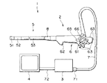
図1に示すように内視鏡システム1は、例えば先端部にCCDなどの固体撮像素子を内蔵した電子内視鏡(以下内視鏡と略記)2と、前記CCDに結像して光電変換された光学像の電気信号を映像信号に変換する信号処理装置などを内蔵した制御装置3と、この信号処理装置3で生成した映像信号を表示する例えばカラーCRTモニタ(以下モニタと略記)4などで主に構成されている。
【0016】
前記内視鏡2は、細長な挿入部5と、この挿入部5の手元側にあって術者が把持する操作部6と、この操作部6の側部から延出してライトガイドや信号系ケーブルや電気系ケーブルなどを内蔵する可撓性のユニバーサルコード7とを備えている。
【0017】
前記挿入部5は、CCDなどの固体撮像素子を内蔵した先端部51と、複数の湾曲節輪を回動自在に連接して上下・左右方向に湾曲自在な湾曲部52と、細長で可撓性を有する軟性管53とを順次連接して構成されている。
【0018】
前記操作部6には前記湾曲部52を上下・左右方向に湾曲させる湾曲操作ノブ61や体腔内に鉗子などの処置具を挿通するための処置具挿入口62や信号処理装置や制御装置あるいは送気・送水・送ガス手段などの周辺機器の操作を行う複数の押釦スイッチ63,63...が設けられている。なお、前記湾曲操作ノブ61は、湾曲部52を上下方向に湾曲操作する回動自在な上下方向用アングルノブ(以下UDノブと略記)65と、前記湾曲部52を左右方向に湾曲操作する回動自在な左右方向用アングルノブ(以下RLノブと略記)66を有している。
【0019】
前記ユニバーサルコード7の手元側端部にはコネクタ部71が設けられており、このコネクタ部71にはCCDで光電変換した被写体像の電気信号を映像信号処理回路に伝送する電気接点部や先端部のノズルに空気などを送るための送気口金や光源装置に接続されるライトガイドが設けられている。
【0020】
なお、前記挿入部5の手元側に位置する弾性を有する軟性管53と操作部6とは座屈を防止するオレドメ8介して連設されている。また、前記制御装置3とモニター4とは映像信号ケーブル72によって接続されている。
【0021】
図2を参照して挿入部5の先端部51及び湾曲部52先端側について説明する。
まず、図に示すように前記先端部51は、金属など硬性の材料で形成された略円柱状の先端部本体10と、この先端部本体10の先端側露出面を無くすように配設される絶縁性の合成樹脂材料で形成された先端カバー11などで構成されている。
【0022】
前記先端部本体10及び先端カバー11には挿入部の長手方向に貫通する観察用孔(不図示),照明用孔12,鉗子チャンネル孔13,送気、送水チャンネル用孔(不図示)などが形成されている。
【0023】
前記照明用孔12には照明レンズ枠12aが例えばエポキシ等の接着剤により固定されており、この照明レンズ枠12a内部に照明レンズ14が前記接着剤などにより固定されている。そして、この照明用孔12の後端部にはライトガイドファイバ15を充填したライトガイド口金16が挿通されており、前記ライトガイドファイバ15が照明レンズ14の後端面に臨むように前記接着剤などにより固定されている。
【0024】
前記鉗子チャンネル孔13には金属材よりなる鉗子チャンネルパイプ17が被嵌されており、前記先端カバー11の先端面から僅かに凹んだ位置になるように先端部本体10に半田などで気密に固定されると共に、前記先端カバー11と鉗子チャンネルパイプ17とは前記接着剤などで固定されている。そして、この鉗子チャンネルパイプ後端部17aの外周全体に前記接着剤などを塗布して鉗子チャンネルチューブ18の内周部を一体的に固定している。なお、前記鉗子チャンネルチューブ18と鉗子チャンネルパイプ後端部17aとは、鉗子チャンネルチューブ18の先端から鉗子チャンネルパイプ後端部17aの手元側に行くに従って鉗子チュンネルチューブ18の内径より大径になるテーパ部根本までを糸巻接着19することによって気密に接着している。
【0025】
なお、前記観察用孔には撮像装置39(図3参照)の固体撮像素子に光学像を結像させる対物レンズ部組がネジなどによって一体的に取り付けられるようになっている。この撮像素子39の後方からは固体撮像素子で光電変換した電気信号を信号処理装置に伝送する信号ケーブル39a(図4参照)が延出している。
【0026】
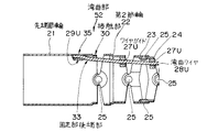
次に、図に示すように前記湾曲部52は、複数の湾曲節輪(以下節輪と略記)、例えば湾曲部52最先端に位置する先端節輪21から第2節輪22,第3節輪23,第4節輪24,...を連接したものであり、例えば上下方向のみに回動する第2節輪22、上下方向及び左右方向の両方に回動できる第3節輪23、第4節輪24...がそれぞれリベット25によって回動自在に連結されている。なお、前記先端節輪21の後方に位置する第2節輪22,第3節輪23,第4節輪24...は、前記先端節輪21と軟性管53の前口金(不図示)とに半田付などで固定されている湾曲ブレード31により湾曲可能な弛みを持たせて被覆されている。
【0027】
前記複数の湾曲節輪21,22,23,24...を連接した湾曲部52と前記先端部本体10とは、前記湾曲部52の先端節輪21の内周面を前記先端部本体10の後端部外周部10aに嵌合させ、図示しないねじを前記先端節輪21に設けた透孔(不図示)を通して後端部外周部10aに形成したネジ穴(不図示)に螺合して一体的に固定されている。
【0028】
また、前記湾曲部52を構成する第2節輪22,第3節輪23,第4節輪24...には湾曲部52を上下左右に湾曲させる湾曲操作ワイヤ(以下湾曲ワイヤと略記)28が挿通する透孔を有するワイヤガイド27がろう付けなどによって一体的に固定されている。
【0029】
図4に示すように前記湾曲ワイヤ28を案内する透孔27aを有するワイヤガイド27は、湾曲部52を湾曲させる上用湾曲ワイヤ28U,下用湾曲ワイヤ28D,左用湾曲ワイヤ28L,右用湾曲ワイヤ28Rにそれぞれ対応して上側ワイヤガイド27U,下側ワイヤガイド27D,左側ワイヤガイド27L,右側ワイヤガイド27Rが設けられている。
【0030】
なお、これら上下左右側ワイヤガイド27U,27D,27L,27Rは、視野基準となる上側ワイヤガイド27Uに対して挿入部内の内蔵物の配置状態によって、各ワイヤガイド間隔を90°前後の範囲で調節して設けられるようになっている。また、内蔵物の配置状態によっては右側ワイヤガイド27Rの外径を太くしても良い。
【0031】
図3に示すように前記節輪22,23,24...に固定されているワイヤガイド27U,27D,27L,27Rの透孔27aを挿通して、先端節輪21まで導かれた上下左右用の湾曲ワイヤ28U,28D、28L、28Rの先端部は、この先端節輪21に設けた上用絞り部29U,下用絞り部29D,左用絞り部29L,右用絞り部29Rにろう付けなどで一体的に固定されて固定部35を形成する。
【0032】
また、上下左右用の湾曲ワイヤ28U,28D、28L、28Rの先端部は、その後方が先端節輪21の内面に対して斜め内側(中心軸側)に傾いた状態に固定してある。これは、前記固定部35に曲げ応力を加えることなく、後方に配置されているワイヤガイド27U,27D,27L,27Rのそれぞれの透孔27aにスムーズに導き易くするためである。
【0033】
前記先端節輪21の後端部で前記上用湾曲ワイヤ28U及び下用湾曲ワイヤ28Dが固定されている上用絞り部29U及び下用絞り部29Dの後方側には先端節輪21の外側上下方向を中心部方向にプレス機などで押圧して形成した中心部方向に出っ張った接触部30が設けられている。
【0034】
この接触部30と上用湾曲ワイヤ28Uとの位置関係は、前記湾曲部52が直線状態のときには離間しているが、前記操作部6のUDノブ65を回動操作して前記上用湾曲ワイヤ28U及び下用湾曲ワイヤ28Dを移動させて湾曲部52を上下方向に対して湾曲させたとき、湾曲ワイヤと接触部30の面とが接触するような高さ及び位置が設定されている。なお、前記接触部30を、湾曲部52が直線状態のとき上用湾曲ワイヤ28Uに接触するように配置してもよい。
【0035】
なお、前記湾曲ワイヤ28U,28D、28L、28Rの先端部の先端節輪21への固定は、ろう付けに限定されるものではなく、半田、接着、圧着、溶接などでもよい。また、前記上下方向のみに回動する第2節輪22には上側ワイヤガイド27Uと下側ワイヤガイド27Dとが固定されている。さらに、前記先端部本体10の外周露出部と湾曲ブレード31の露出部は湾曲ゴム32によって気密に被覆され両端部が糸巻接着19によって接着固定されている。
【0036】
図5に示すように前記軟性管53内を挿通して操作部6に設けた処置具挿入口62に延出される鉗子チャンネルチューブ18は、操作部の先端部に設けられたオレドメ8先端を中心に、前記軟性管53先端側とオレドメ8手元側とに跨がる長さに形成した鉗子チャンネル補強熱収縮チューブ81を外装している。この鉗子チャンネル補強熱収縮チューブ81は、FEPや架橋ポリエチレン(商品名イラックス)などの軟性部材で形成されており、内径寸法が、収縮前に鉗子チャンネルチューブ18の外径寸法よりも大きく、収縮後に鉗子チャンネルチューブ18の外周面にぴったり密着するものである。このため、鉗子チャンネル補強熱収縮チューブ81をスムーズに所定の位置に配置することができ、熱収縮後は、鉗子チャンネルチューブ18に密着して屈曲しても隙間が生じず十分な折れ止め効果を有する。
【0037】
上述のように構成した内視鏡2の湾曲部52の作用を説明する。
まず、前記操作部6のUDノブ65を回動操作して前記上用湾曲ワイヤ28Uを牽引操作して湾曲部52を、図6に示す直線状態から図7に示すように徐々に湾曲させていく。
【0038】
すると、図6に示すように直線状態のとき、先端節輪21に設けた接触部30に接触していなかった右用湾曲ワイヤ28Rが、図7に示すように固定部後端部33が屈曲した後、前記接触部30に接触する。
【0039】
ここで、さらに上用湾曲ワイヤ28Uを牽引操作して湾曲部52を湾曲させると、前記右用湾曲ワイヤ28Rが接触部30に接触しているため、固定部後端部33での屈曲角度が変わることなく湾曲していく。すなわち、前記右用湾曲ワイヤ28Rが接触部30に接触することによって、上用湾曲ワイヤ28Uが曲げ応力を受ける。このため、上下方向の最大湾曲操作を繰り返し行っても、ろう付けの際の熱などの影響により強度の低下している固定部近傍に繰り返し曲げ応力が集中しない。なお、下用湾曲ワイヤを牽引操作して湾曲部を下方向に湾曲させたときも同様である。また、本実施形態では接触部を上下方向にだけ形成しているが、左右方向に形成してもよいことはいうまでもない。さらに、前記接触部30の存在は、本実施形態のように上下左右用の湾曲ワイヤ28U,28D,28L,28Rを、斜め内側に傾いた状態で固定したものに対して、その振り幅を小さくする効果が大きいが、これに限定されず、先端節輪21の内面に対してまっすぐ平面に固定したものに対しても使用可能なものであり、十分な効果を有することはいうまでもない。
【0040】
このように、先端節輪に湾曲ワイヤ先端部を固定した固定部の後方に、湾曲操作時少なくとも最大湾曲前に、前記上用湾曲ワイヤが接触する接触部を設けたことにより、湾曲ワイヤの固定部後端部や湾曲ワイヤの固定部への繰り返し曲げ応力の集中を緩和することができる。このことにより、上下方向湾曲時に屈曲していた、ろう付けの際の熱などの影響で強度の低下している固定部後端部近傍での折れが無くなり、湾曲ワイヤの耐性が向上する。
【0041】
また、内視鏡挿入部内の内蔵物に接しない先端節輪の少なくとも上下方向の一部を、中心部方向に押圧するだけで、部品点数を増やすことなく、且つ先端部本体の外径を大径にすることなく、容易に湾曲ワイヤが接触する接触部を構成することができる。このことにより、内視鏡挿入部内の内蔵物に悪影響の生じない、接触部が安価に形成される。
【0042】
さらに、オレドメ先端を略中心位置にして鉗子チャンネルチューブに鉗子チャンネル補強熱収縮チューブを外装して密着させたことにより、鉗子チャンネルチューブの外径のバラツキに関係なく、鉗子チャンネルチューブの座屈耐性を向上させることができる。
【0043】
又、節輪内の内蔵物の充填率によってワイヤガイドの外径寸法を適宜設定することによって、節輪内の内蔵物の充填率を調節して節輪内の内蔵物の乱れを防止することができる。
【0044】
更に、鉗子チャンネルパイプ後端部に手元側に行くに従って鉗子チュンネルチューブの内径より大径になるテーパー部を設けることによって、鉗子チャンネルパイプ後端外周部に塗布した接着剤の鉗子チャンネル内への流入を防止することができると共に、処置具挿通時に引掛りのない構造にすることができる。
【0045】
なお、前記上用湾曲ワイヤ28Uを牽引操作したとき、前記固定部後端部33を支点に前記上用湾曲ワイヤ28Uが上下方向に動くので、前記接触部30を固定部後端部33に近づけて配置することにより、前記上用湾曲ワイヤ28Uが上下動を開始する前に、前記上用湾曲ワイヤ28Uを接触部30に接触させることができる。
【0046】
また、視野上方向のワイヤ固定部及びワイヤガイドは、視野真上方向に固定するようにした方が良いが、視野真上方向には送気、送水管の接続パイプなど硬質部を有する内蔵物が多く配設されているので、内蔵物とワイヤ固定部などが干渉することがあった。この干渉を避けるために、湾曲節輪の内径を大径化することが考えられるが、挿入部外径寸法が太径になって被検者の苦痛が大きくなるという欠点がある。このため、上方向に配置するワイヤ固定部及びワイヤガイドを視野真上方向に対して左右どちらかに10°以上位置ずれさせていた。しかし、この方法では内視鏡湾曲操作として頻繁に使う上方向湾曲時に、内視鏡先端の動きが視野真上方向に対して左右にずれ、真上方向を観察したつもりが、実際は左右に位置ずれして内視鏡検査に支障をきたす可能性があった。
【0047】
このため、図8に示すように先端節輪21に設けられている上用絞り部29Uに固定される上用湾曲ワイヤ28Uは、上方向視野の中心位置に対して左側に約15°ずらした位置にワイヤ固定部35を設ける一方、前記先端節輪21の後方に連接する第2節輪22の上側ワイヤガイド27Uを前記先端節輪21の上方向視野に対して中心位置に固定すると共に、前記第2節輪22が上下方向のみに回動するようにしている。このため、上下方向の湾曲操作の際、最大湾曲角度の大きい上方向への湾曲時に、先端節輪21の先端部が左側にねじれて湾曲することを防止して、真上方向にスムーズに湾曲させることができる。このことにより、前記先端節輪21の真上方向に配置される送気、送水チャンネル38の接続パイプなどが上側ワイヤ固定部に干渉する場合、上側ワイヤ固定部を左右にずらしても、上方向の湾曲状態が左右に傾くことがないので先端節輪の大径化を防止することができる。
【0048】
図9及び図10は本発明の第2実施形態に係り、図9は湾曲部の概略構成を示す上面図、図10は湾曲状態の湾曲部内の湾曲ワイヤと第1節輪との関係を説明する断面図である。
【0049】
本実施形態では、前記第1実施形態で接触部30を先端節輪21の外側上下方向を中心部方向にプレス機などで押圧して中心部方向に出っ張っらせて形成したのに対して、図に示すように先端節輪21の後端部に全周にわたる小径部41を設け、湾曲中に湾曲ワイヤが前記小径部41に接触するようにしている。その他の構成は前記実施形態と同様であり、同部材には同符号を付して説明を省略する。
【0050】
このように、湾曲ワイヤが接触する小径部を先端節輪の後端部に全周に渡って設けることにより、上下湾曲方向のみならず、上下左右全ての湾曲方向に対する湾曲ワイヤについても固定部後端部に繰り返し曲げ応力が集中することを防止することができる。その他の作用及び効果は前記実施形態と同様である。
【0051】
図11は本発明の第3実施形態に係る湾曲状態の湾曲部内の湾曲ワイヤと第1節輪との関係を説明する断面図である。
【0052】
本実施形態では、前記第1実施形態で接触部30を先端節輪21の外側上下方向を中心部方向にプレス機などで押圧して中心部方向に出っ張っらせて形成したのに対して、図に示すように先端節輪21の後端面とワイヤ固定部35との間に凸部品42を接着等によって固定して、湾曲中に湾曲ワイヤが前記凸部品42に接触するようにしている。なお、前記凸部品42は合成樹脂の成型品や、金属部材からなる加工品であり、湾曲ワイヤとの当接部の形状を球状又はR面取りを施して形成して、当接部分で湾曲ワイヤに応力が集中することを防いでいる。また、前記凸部品42の先端節輪21の後端面とワイヤ固定部35との間への固定は接着に限定されるものではなく、ろう付けや半田付、あるいは溶接などであってもよい。
【0053】
このように、湾曲ワイヤが接触する凸部品を先端節輪の後端部に固定することによって、凸部品の寸法精度が出し易く、凸部品の固定位置を最適な位置に適宜設定することができる。このことにより、湾曲時の湾曲ワイヤへの応力集中を最も少なくするように設定することができる。その他の作用及び効果は前記実施形態と同様である。
【0054】
図12は本発明の第4実施形態に係る湾曲状態の湾曲部内の湾曲ワイヤと第1節輪との関係を説明する断面図である。
【0055】
本実施形態では、前記第1実施形態で接触部30を先端節輪21の外側上下方向を中心部方向にプレス機などで押圧して中心部方向に出っ張っらせて形成したのに対して、図に示すように先端節輪21の後方に連接する第2節輪22の先端部に接触部43を設けている。なお、前記接触部43は、第2節輪22の先端部を第1実施形態のようにプレス等で押圧して形成したものであっても、第2節輪22の先端部分に第2実施形態のように全周に渡って小径部を設けるようにしたものであっても、第3実施形態のように別部品を固定するように設けたものであってもよい。なお、前記接触部43を設ける位置は、第2節輪22の先端部に限定されるものではなく、少なくとも湾曲部52が湾曲中に湾曲ワイヤが接触部に接触すればよい。また、湾曲部52が直線状態のとき、上用湾曲ワイヤ28Uが接触するようにしても良い。その他の構成及び作用は前記第1実施形態と同様であり、同部材には同符号を付して説明を省略する。
【0056】
このように、先端節輪の後方に位置する第2節輪に接触部を設けることによって、内蔵物の硬質部と接触部との干渉を受け難くすることができる。このことにより、たとえ内蔵物の硬質部長の長い内視鏡であっても、接触部と内蔵物の硬質部との干渉がなくなるので、内蔵物の耐性の高い内視鏡が構成される。
【0057】
なお、本発明は、これらの実施形態に限定されるものではなく、例えば第1実施形態の接触部を先端節輪の後端部でなく、固定部と第2節輪のワイヤガイドとの間であればどの位置に設けてもよい。また、接触部と湾曲ワイヤとは、湾曲部が直線状態のときから接触している状態でも、直線状態では接触していない状態であってもよく、湾曲ワイヤ牽引時に接触すればよい。本発明の趣旨を逸脱しない範囲で種々変形実施可能である。
【0058】
[付記]
1.複数の湾曲節輪を回動自在に連接して形成されている湾曲部を湾曲操作する湾曲操作ワイヤを、前記湾曲部湾曲節輪に設けたワイヤガイドに挿通して先端側に配置されている先端湾曲節輪に導き、この先端湾曲節輪に前記湾曲操作ワイヤ先端を固定する固定部を設けた内視鏡において
前記先端湾曲節輪の湾曲操作ワイヤ先端が固定されている固定部と、この固定部の後方に配置された湾曲節輪に設けられたワイヤガイドとの間に、少なくとも前記湾曲操作ワイヤ牽引操作時に、前記湾曲操作ワイヤが接触する接触部を設けた内視鏡。
【0059】
2.湾曲操作ワイヤ先端を湾曲節輪に対し、その後方が斜め内側に傾くように固定した固定部を有する内視鏡において、
前記固定部とこの固定部の後方のワイヤガイドとの間で湾曲操作ワイヤ牽引時、この湾曲操作ワイヤが接触する接触部を湾曲用節輪に設けた内視鏡。
【0060】
3.前記湾曲操作ワイヤ先端を先端湾曲節輪にろう付けで固定した付記1記載の内視鏡。
【0061】
4.前記接触部を、先端湾曲節輪またはこの先端湾曲節輪に連接する湾曲節輪の端部を変形させて形成した付記1記載の内視鏡。
【0062】
5.前記接触部を、前記湾曲節輪と異なる構成部材を固定して形成した付記1記載の内視鏡。
【0063】
6.前記接触部が、前記湾曲操作ワイヤ先端が固定されている固定部と、この固定部の後方のワイヤガイドとの間に位置し、前記ワイヤ固定部及びワイヤガイド固定部の内径より小径に形成している付記1ないし付記4記載の内視鏡。
【0064】
7.複数の湾曲節輪を回動自由に接続し、複数の湾曲ワイヤを前記湾曲節輪に設けたワイヤガイド孔に挿通させ、先端に位置する先端湾曲節輪に前記湾曲ワイヤ先端を固定して内視鏡先端部を上下左右に湾曲操作する内視鏡において、
視野上方向に湾曲操作させる湾曲ワイヤを挿通するワイヤガイドを視野の上方向に配置する一方、前記先端湾曲節輪の湾曲ワイヤ先端を固定する固定部を視野上方向から左右に位置ずれさせて固定した内視鏡。
【0065】
8.湾曲ワイヤ先端が固定される先端湾曲節輪の後方に連接される湾曲節輪を、視野の上下方向にのみ回動するように接続した付記7記載の内視鏡。
【0066】
9.視野の上方向の湾曲角度はその他の方向の湾曲角度より大きくした付記7及び付記8記載の内視鏡。
【0067】
【発明の効果】
以上説明したように本発明によれば、挿入部を大径にすることなく、湾曲ワイヤ先端を固定した固定部近傍での繰り返し曲げ応力の集中を避けて、湾曲ワイヤの耐久性を向上させる内視鏡を提供することができる。
【図面の簡単な説明】
【図1】図1ないし図8は本発明の第1実施形態に係り、図1は内視鏡システムの概略構成を示す説明図
【図2】先端部と湾曲部の一部との構成を説明する断面図
【図3】図2のA−A断面図
【図4】図2のB−B断面図
【図5】折れ止め内部を説明する図
【図6】直線状態の湾曲部内部の湾曲ワイヤを示す図
【図7】湾曲状態の湾曲部内部の湾曲ワイヤを示す図
【図8】直線状態の湾曲部内部に配設されている湾曲ワイヤ先端の固定部及びワイヤガイドを示す図
【図9】図9及び図10は本発明の第2実施形態に係り、図9は湾曲部の概略構成を示す上面図
【図10】湾曲状態の湾曲部内の湾曲ワイヤと第1節輪との関係を説明する断面図
【図11】本発明の第3実施形態に係る湾曲状態の湾曲部内の湾曲ワイヤと第1節輪との関係を説明する断面図
【図12】本発明の第4実施形態に係る湾曲状態の湾曲部内の湾曲ワイヤと第1節輪との関係を説明する断面図
【符号の説明】
21…先端節輪
22…第2節輪
27…ワイヤガイド
28…湾曲ワイヤ
30…接触部
33…固定部後端部
52…湾曲部[0001]
BACKGROUND OF THE INVENTION
The present invention relates to an endoscope that bends a bending portion by pulling a bending operation wire, and more particularly, to an improvement in the vicinity of a fixing portion between a bending operation wire and a bending nodal ring for bending the bending portion in the vertical and horizontal directions.
[0002]
[Prior art]
2. Description of the Related Art Conventionally, an endoscope apparatus in which an elongated endoscope is inserted into a body cavity or the like to observe a test site and perform various treatments has been widely used.
[0003]
In general, an endoscope having a flexible insertion portion is provided with a bending portion formed by connecting a plurality of curved node rings to the insertion portion, and a pulling member such as a bending operation wire (hereinafter abbreviated as a bending wire) connected to the bending portion. The bending portion is bent in a desired direction by advancing and retreating. In this way, by bending the bending portion in a desired direction at a desired angle, the observation optical system disposed at the distal end portion of the endoscope insertion portion is directed in the target direction, so that the observation or test site can be directed. Easy to insert.
[0004]
The bending wire that is inserted through the endoscope insertion portion and led to the distal bending node ring disposed at the forefront of the bending portion is, for example, in the bending portion formed on the rear portion of the distal bending node ring. It was fixed by silver brazing after inserting the wire. Then, when guiding the bending wire to the distal bending node ring, the bending wire is inserted into a through hole of a wire guide provided on the inner peripheral surface of the bending node ring and guided to the distal end.
[0005]
In Japanese Patent Publication No. 2-62248, as an attachment structure of the bending wire, a groove extending in the axial direction is provided on the outer peripheral surface of the distal end body, and the node ring fitted to the distal end body matches the groove. A method is disclosed in which a hole to be drilled is formed, a distal end portion of a bending wire is inserted into the groove and bent outward, and the bent end portion is inserted into a hole provided in the node ring and joined to the node ring. Has been.
[0006]
In addition, as a structure to which the above-mentioned Japanese Patent Publication No. 2-62248 is applied, Japanese Utility Model Publication No. 7-24083 discloses a node ring fitted to a tip body, a ring portion to which a bending wire is fixed, and this ring portion. A curved joint ring that is abutted rearward, fitted to the outer periphery of the tip end body, and fixed is disclosed.
[0007]
[Problems to be solved by the invention]
However, in the above-described bending wire mounting structure, the wire guide into which the pulled bending wire is inserted when the bending portion is formed by connecting the plurality of bending nodes by bending the bending wire forward and backward. However, it moves in the outer peripheral direction of the bending wire fixing portion with respect to the central axis of the inner diameter of the distal-side bending node ring to which the bending wire tip portion is fixed.
[0008]
For this reason, the bending wire is bent in the outer peripheral direction in the vicinity of the bending wire fixing portion between the bending wire fixing portion and the wire guide passing through the bending wire positioned behind the bending wire fixing portion. End up.
[0009]
Therefore, the bending wire is repeatedly bent between the bending wire fixing portion and the wire guide behind the bending wire fixing portion by repeatedly performing the up / down bending operation or the left / right bending operation, and bending stress is applied to the bending portion. concentrate. Further, since the bent portion is in the vicinity of the bending wire fixing portion, it is heated when the bending wire is silver brazed to the distal bending node ring, and the strength is reduced. Due to these two factors, the bending wire was easily broken in the vicinity of the bending wire fixing portion.
[0010]
Further, in the Japanese Patent Publication No. 2-62248 and the Japanese Utility Model Publication No. 7-24083, it is necessary to process a groove through which the bending wire is inserted into the tip portion main body. There is no room for the mounting space for the component parts, and as a result, there is a drawback that the diameter of the tip portion main body increases.
[0011]
The present invention has been made in view of the above circumstances, and avoids the concentration of repeated bending stress in the vicinity of the fixing portion where the distal end of the bending wire is fixed without increasing the diameter of the insertion portion, thereby improving the durability of the bending wire. An object is to provide an improved endoscope.
[0012]
[Means for Solving the Problems]
An endoscope according to the present invention is connected to a bending portion that is bent by a bending operation wire, a distal-end bending node ring that forms a distal end of the bending portion, and a proximal end side of the distal-end bending node ring. A cylindrical curved node ring having an inner diameter smaller than the distal curved node ring, and an inner surface of the distal curved node ring, and the distal end portion of the bending operation wire is disposed at the distal curved portion. A fixing portion that fixes the inside of the node ring, a wire guide that is provided inside the bending node ring, and passes through the bending operation wire; The tip curved node ring A contact portion that is provided on an inner surface of the wire guide side than the fixed portion and that forms a step so as to make a business trip in a direction toward a center portion from an inner wall of the curved node ring in order to contact the bending operation wire. It is characterized by having.
[0013]
According to this configuration, when the bending portion is bent by operating the bending wire, the bending wire comes into contact with the contact portion, so that stress is not concentrated in the vicinity of the fixing portion and the bending portion.
[0014]
DETAILED DESCRIPTION OF THE INVENTION
Embodiments of the present invention will be described below with reference to the drawings.
1 to 8 relate to a first embodiment of the present invention, FIG. 1 is an explanatory diagram showing a schematic configuration of an endoscope system, and FIG. 2 is a sectional view illustrating a configuration of a distal end portion and a part of a bending portion. 3 is a cross-sectional view taken along the line AA in FIG. 2, FIG. 4 is a cross-sectional view taken along the line BB in FIG. 2, FIG. 5 is a view illustrating the inside of the bend prevention, and FIG. FIG. 7 is a view showing a bending wire inside the bending portion in a bending state, and FIG. 8 is a view showing a fixing portion and a wire guide at the distal end of the bending wire disposed inside the bending portion in a straight state.
[0015]
As shown in FIG. 1, an endoscope system 1 includes, for example, an electronic endoscope (hereinafter abbreviated as an endoscope) 2 having a built-in solid-state image pickup device such as a CCD at its distal end, and photoelectric conversion by forming an image on the CCD. A
[0016]
The
[0017]
The
[0018]
The
[0019]
A
[0020]
The
[0021]
The
First, as shown in the figure, the
[0022]
The
[0023]
An illumination lens frame 12a is fixed to the
[0024]
A
[0025]
Note that an objective lens unit for forming an optical image on the solid-state image sensor of the imaging device 39 (see FIG. 3) is integrally attached to the observation hole with a screw or the like. A signal cable 39a (see FIG. 4) that transmits an electrical signal photoelectrically converted by the solid-state image sensor to the signal processing device extends from behind the
[0026]
Next, as shown in the figure, the bending
[0027]
The plurality of curved node rings 21, 22, 23, 24. . . The bending
[0028]
Further, the second
[0029]
As shown in FIG. 4, the
[0030]
The upper, lower, left, and right side wire guides 27U, 27D, 27L, and 27R are adjusted within a range of about 90 ° with respect to the
[0031]
As shown in FIG. 3, the node rings 22, 23, 24. . . The distal ends of the up / down / left / right
[0032]
Further, the distal ends of the bending
[0033]
On the rear side of the upper restricting
[0034]
The positional relationship between the
[0035]
Note that the fixing of the distal ends of the bending
[0036]
As shown in FIG. 5, the
[0037]
The operation of the bending
First, the
[0038]
Then, in the straight state as shown in FIG. 6, the bending wire for right 28R that is not in contact with the
[0039]
Here, when the
[0040]
In this manner, the bending wire is fixed by providing a contact portion that comes into contact with the upper bending wire at least before the maximum bending at the time of bending operation, behind the fixing portion where the bending wire tip is fixed to the distal node ring. The concentration of repeated bending stress on the rear end of the part and the fixed part of the bending wire can be alleviated. As a result, bending near the rear end of the fixed portion, which has been bent at the time of bending in the vertical direction and has reduced strength due to the influence of heat during brazing, is eliminated, and the resistance of the bending wire is improved.
[0041]
In addition, it is possible to increase the outer diameter of the distal end body without increasing the number of parts by simply pressing at least a part of the distal node ring that does not contact the built-in object in the endoscope insertion portion in the vertical direction. A contact portion with which the bending wire comes into contact with each other can be easily configured without having a diameter. As a result, a contact portion that does not adversely affect the internal components in the endoscope insertion portion is formed at low cost.
[0042]
Furthermore, the forceps channel tube buckling resistance can be improved regardless of variations in the outer diameter of the forceps channel tube by attaching the forceps channel reinforcing heat-shrinkable tube to the forceps channel tube, with the tip of the oledome at the approximate center position. Can be improved.
[0043]
In addition, by appropriately setting the outer diameter of the wire guide according to the filling rate of the built-in material in the node ring, the disturbance of the built-in material in the node ring can be prevented by adjusting the filling rate of the built-in material in the node ring. Can do.
[0044]
Furthermore, by providing a taper portion having a diameter larger than the inner diameter of the forceps channel tube toward the proximal side at the rear end of the forceps channel pipe, the adhesive applied to the outer periphery of the rear end of the forceps channel pipe enters the forceps channel. Inflow can be prevented, and a structure without catching when the treatment instrument is inserted can be obtained.
[0045]
Note that when the
[0046]
Also, it is better to fix the wire fixing part and wire guide in the upward direction of the visual field in the direction directly above the visual field, but in the upward direction of the visual field, a built-in object having a hard part such as a connection pipe for air supply or water supply pipe Since many of them are arranged, built-in objects and wire fixing parts may interfere with each other. In order to avoid this interference, it is conceivable to increase the inner diameter of the curved node ring, but there is a disadvantage that the outer diameter of the insertion portion becomes larger and the pain of the subject increases. For this reason, the wire fixing portion and the wire guide arranged in the upward direction are displaced by 10 ° or more to the left or right with respect to the direction directly above the visual field. However, in this method, when the upward bending is frequently used as the bending operation of the endoscope, the movement of the endoscope tip is shifted to the left and right with respect to the direction directly above the visual field. There was a possibility that it would shift and interfere with endoscopy.
[0047]
Therefore, as shown in FIG. 8, the
[0048]
9 and 10 relate to the second embodiment of the present invention, FIG. 9 is a top view showing a schematic configuration of the bending portion, and FIG. 10 explains the relationship between the bending wire in the bending portion and the first joint ring. FIG.
[0049]
In the present embodiment, the
[0050]
In this way, by providing a small-diameter portion that contacts the bending wire over the entire circumference at the rear end portion of the distal node ring, not only the vertical bending direction but also the bending wire for all the vertical and horizontal bending directions can be It is possible to prevent the bending stress from being concentrated repeatedly at the end. Other operations and effects are the same as in the above embodiment.
[0051]
FIG. 11 is a cross-sectional view illustrating the relationship between the bending wire in the bending portion in the bending state and the first joint ring according to the third embodiment of the present invention.
[0052]
In the present embodiment, the
[0053]
In this way, by fixing the convex component that comes into contact with the bending wire to the rear end portion of the tip node ring, the dimensional accuracy of the convex component can be easily obtained, and the fixing position of the convex component can be appropriately set to the optimum position. . Thus, the stress concentration on the bending wire during bending can be set to be minimized. Other operations and effects are the same as in the above embodiment.
[0054]
FIG. 12 is a cross-sectional view illustrating the relationship between the bending wire in the bending portion in the bending state and the first joint ring according to the fourth embodiment of the present invention.
[0055]
In the present embodiment, the
[0056]
Thus, by providing the contact portion on the second node ring located behind the tip node ring, interference between the hard portion of the built-in object and the contact portion can be made difficult. This eliminates interference between the contact portion and the hard part of the built-in object even in an endoscope having a long hard part length of the built-in object, so that an endoscope having high resistance of the built-in object is configured.
[0057]
The present invention is not limited to these embodiments. For example, the contact portion of the first embodiment is not the rear end portion of the front end node ring, but between the fixed portion and the wire guide of the second node ring. Any position may be used. In addition, the contact portion and the bending wire may be in contact with each other since the bending portion is in a straight state, or may be in a state in which the bending portion is not in contact in a straight state, and may be in contact with each other when the bending wire is pulled. Various modifications can be made without departing from the spirit of the present invention.
[0058]
[Appendix]
1. A bending operation wire for bending a bending portion formed by connecting a plurality of bending node rings rotatably is inserted into a wire guide provided in the bending portion bending node ring and disposed on the distal end side. In an endoscope provided with a fixing portion that guides to a distal bending node and fixes the distal end of the bending operation wire to the distal bending node
At least during the pulling operation of the bending operation wire, between the fixing portion where the distal end of the bending operation wire of the distal bending node ring is fixed and the wire guide provided on the bending node ring arranged behind the fixing portion. An endoscope provided with a contact portion with which the bending operation wire comes into contact.
[0059]
2. In an endoscope having a fixing part in which the distal end of the bending operation wire is fixed to the bending node ring so that the rear thereof is inclined obliquely inward,
An endoscope in which a bending node ring is provided with a contact portion that contacts the bending operation wire when the bending operation wire is pulled between the fixing portion and a wire guide behind the fixing portion.
[0060]
3. The endoscope according to appendix 1, wherein the distal end of the bending operation wire is fixed to the distal bending node ring by brazing.
[0061]
4). The endoscope according to appendix 1, wherein the contact portion is formed by deforming an end portion of a curved node ring connected to the distal curved node ring or the distal curved node ring.
[0062]
5. The endoscope according to appendix 1, wherein the contact portion is formed by fixing a constituent member different from the curved node ring.
[0063]
6). The contact portion is positioned between a fixing portion to which the distal end of the bending operation wire is fixed and a wire guide behind the fixing portion, and is formed to have a smaller diameter than the inner diameters of the wire fixing portion and the wire guide fixing portion. The endoscope according to appendix 1 to
[0064]
7. A plurality of bending nodes are freely connected, a plurality of bending wires are inserted into wire guide holes provided in the bending nodes, and the distal end of the bending wire is fixed to the distal bending node located at the tip. In an endoscope that bends the tip of the endoscope vertically and horizontally,
A wire guide for inserting a bending wire to bend in the upward direction of the visual field is arranged in the upward direction of the visual field, and a fixing part for fixing the distal end of the bending wire of the distal bending node is displaced from the upward direction of the visual field to the left and right. Endoscope.
[0065]
8). The endoscope according to
[0066]
9. The endoscope according to
[0067]
【The invention's effect】
As described above, according to the present invention, the inner diameter of the bending wire can be improved without increasing the diameter of the insertion portion and avoiding the concentration of repeated bending stress in the vicinity of the fixing portion where the distal end of the bending wire is fixed. An endoscope can be provided.
[Brief description of the drawings]
FIG. 1 to FIG. 8 relate to a first embodiment of the present invention, and FIG. 1 is an explanatory view showing a schematic configuration of an endoscope system.
FIG. 2 is a cross-sectional view illustrating a configuration of a tip portion and a part of a bending portion
3 is a cross-sectional view taken along the line AA in FIG.
4 is a cross-sectional view taken along the line BB in FIG.
FIG. 5 is a diagram for explaining the inside of the folding stop
FIG. 6 is a diagram showing a bending wire inside a bending portion in a straight state.
FIG. 7 is a diagram showing a bending wire inside a bending portion in a bending state.
FIG. 8 is a view showing a fixing portion and a wire guide of a bending wire tip disposed inside a bending portion in a straight state.
FIGS. 9 and 10 relate to a second embodiment of the present invention, and FIG. 9 is a top view showing a schematic configuration of a bending portion.
FIG. 10 is a cross-sectional view for explaining the relationship between the bending wire in the bending portion in the bending state and the first joint ring.
FIG. 11 is a cross-sectional view illustrating the relationship between the bending wire in the bending portion in the bending state and the first joint ring according to the third embodiment of the present invention.
FIG. 12 is a cross-sectional view illustrating the relationship between the bending wire in the bending portion in the bending state and the first joint ring according to the fourth embodiment of the present invention.
[Explanation of symbols]
21 ... Tip joint ring
22 ... Second joint ring
27 ... Wire guide
28 ... Bending wire
30 ... Contact part
33 ... Fixed part rear end part
52 ... curved part
Claims (1)
前記湾曲部の先端を構成する筒状に形成された先端湾曲節輪と、
前記先端湾曲節輪の基端側に連結されて前記湾曲部を構成し、前記先端湾曲節輪よりも小径な内径を有する筒状の湾曲節輪と、
前記先端湾曲節輪の内面に設けられ、前記湾曲操作ワイヤの先端部を前記先端湾曲節輪の内部に固定する固定部と、
前記湾曲節輪の内部に設けられ、前記湾曲操作ワイヤを挿通するワイヤガイドと、
前記先端湾曲節輪の前記固定部よりも前記ワイヤガイド側の内面に設けられ、前記湾曲操作ワイヤに接触するために前記湾曲節輪の内壁よりも中心部方向に出張するように段を形成する接触部と、
を有することを特徴とする内視鏡。A bending portion that is bent by a bending operation wire;
A tip-curved nodal ring formed in a cylindrical shape that constitutes the tip of the bending portion;
A cylindrical curved node ring that is connected to the proximal end side of the distal curved node ring to form the curved portion, and has an inner diameter smaller than the distal curved node ring,
A fixing portion provided on an inner surface of the distal bending node ring, and fixing a distal end portion of the bending operation wire to the inside of the distal bending node ring;
A wire guide provided inside the curved node ring and for inserting the bending operation wire;
A step is formed on the inner surface of the distal curved node ring on the wire guide side than the fixed portion, so as to make a business trip toward the central portion of the curved node ring in order to contact the bending operation wire. A contact portion;
The endoscope characterized by having.
Priority Applications (1)
| Application Number | Priority Date | Filing Date | Title |
|---|---|---|---|
| JP25365395A JP3717560B2 (en) | 1995-09-29 | 1995-09-29 | Endoscope |
Applications Claiming Priority (1)
| Application Number | Priority Date | Filing Date | Title |
|---|---|---|---|
| JP25365395A JP3717560B2 (en) | 1995-09-29 | 1995-09-29 | Endoscope |
Publications (2)
| Publication Number | Publication Date |
|---|---|
| JPH0994218A JPH0994218A (en) | 1997-04-08 |
| JP3717560B2 true JP3717560B2 (en) | 2005-11-16 |
Family
ID=17254323
Family Applications (1)
| Application Number | Title | Priority Date | Filing Date |
|---|---|---|---|
| JP25365395A Expired - Fee Related JP3717560B2 (en) | 1995-09-29 | 1995-09-29 | Endoscope |
Country Status (1)
| Country | Link |
|---|---|
| JP (1) | JP3717560B2 (en) |
Families Citing this family (7)
| Publication number | Priority date | Publication date | Assignee | Title |
|---|---|---|---|---|
| JP3651329B2 (en) * | 1999-09-30 | 2005-05-25 | フジノン株式会社 | Angle section of endoscope |
| JP2010068891A (en) * | 2008-09-17 | 2010-04-02 | Fujifilm Corp | Endoscope |
| JP5378044B2 (en) * | 2009-04-09 | 2013-12-25 | オリンパス株式会社 | Medical instrument parts and medical instruments |
| JP5367518B2 (en) * | 2009-09-17 | 2013-12-11 | 朝日インテック株式会社 | Medical endoscope, method for manufacturing medical endoscope, assembly of medical endoscope and treatment instrument for medical endoscope, and medical endoscope and medical endoscope image processing system |
| KR101180820B1 (en) * | 2010-11-25 | 2012-09-07 | 한국과학기술원 | Shape lockable apparatus for flexible tubes |
| JP6360639B1 (en) | 2016-12-26 | 2018-07-18 | オリンパス株式会社 | Endoscope |
| CN107174187A (en) * | 2017-04-12 | 2017-09-19 | 深圳开立生物医疗科技股份有限公司 | A kind of steel wire cord-fixing structure of achievable fast assembling-disassembling |
-
1995
- 1995-09-29 JP JP25365395A patent/JP3717560B2/en not_active Expired - Fee Related
Also Published As
| Publication number | Publication date |
|---|---|
| JPH0994218A (en) | 1997-04-08 |
Similar Documents
| Publication | Publication Date | Title |
|---|---|---|
| JP2987452B2 (en) | Endoscope | |
| CN105193372B (en) | Endoscope with signal cable | |
| WO2013039059A1 (en) | Endoscope position detecting probe | |
| JP3717560B2 (en) | Endoscope | |
| JP5175639B2 (en) | Endoscope and its assembly method | |
| CN112788977A (en) | Endoscope bending part | |
| US10478049B2 (en) | Endoscope | |
| JP2001128937A (en) | Electronic endoscope | |
| JP6401004B2 (en) | Endoscope cable module | |
| CN108778144B (en) | Endoscope with a detachable handle | |
| JPH1119035A (en) | Endoscope | |
| JP3831273B2 (en) | Electronic endoscope | |
| JP3969856B2 (en) | Endoscope | |
| JP3586180B2 (en) | Endoscope shape detection probe | |
| JPS6398621A (en) | Endoscope | |
| JP2019013665A (en) | Endoscope and method of fabricating endoscope | |
| JP4504076B2 (en) | Endoscope | |
| JP2004121860A (en) | Endoscope system | |
| JP3662048B2 (en) | Electronic endoscope | |
| JP3791764B2 (en) | Endoscope device | |
| JPH07116109A (en) | Endoscope | |
| JP4127794B2 (en) | Endoscope | |
| JP3706324B2 (en) | Imaging device | |
| JP4634661B2 (en) | End of the endoscope | |
| JPH0975300A (en) | Endoscope and endoscope apparatus using the same |
Legal Events
| Date | Code | Title | Description |
|---|---|---|---|
| A977 | Report on retrieval |
Free format text: JAPANESE INTERMEDIATE CODE: A971007 Effective date: 20040330 |
|
| A131 | Notification of reasons for refusal |
Free format text: JAPANESE INTERMEDIATE CODE: A131 Effective date: 20040420 |
|
| A521 | Written amendment |
Free format text: JAPANESE INTERMEDIATE CODE: A523 Effective date: 20040621 |
|
| A131 | Notification of reasons for refusal |
Free format text: JAPANESE INTERMEDIATE CODE: A131 Effective date: 20050308 |
|
| A521 | Written amendment |
Free format text: JAPANESE INTERMEDIATE CODE: A523 Effective date: 20050509 |
|
| TRDD | Decision of grant or rejection written | ||
| A01 | Written decision to grant a patent or to grant a registration (utility model) |
Free format text: JAPANESE INTERMEDIATE CODE: A01 Effective date: 20050823 |
|
| A61 | First payment of annual fees (during grant procedure) |
Free format text: JAPANESE INTERMEDIATE CODE: A61 Effective date: 20050831 |
|
| FPAY | Renewal fee payment (event date is renewal date of database) |
Free format text: PAYMENT UNTIL: 20080909 Year of fee payment: 3 |
|
| FPAY | Renewal fee payment (event date is renewal date of database) |
Free format text: PAYMENT UNTIL: 20090909 Year of fee payment: 4 |
|
| FPAY | Renewal fee payment (event date is renewal date of database) |
Free format text: PAYMENT UNTIL: 20090909 Year of fee payment: 4 |
|
| FPAY | Renewal fee payment (event date is renewal date of database) |
Free format text: PAYMENT UNTIL: 20100909 Year of fee payment: 5 |
|
| FPAY | Renewal fee payment (event date is renewal date of database) |
Free format text: PAYMENT UNTIL: 20110909 Year of fee payment: 6 |
|
| FPAY | Renewal fee payment (event date is renewal date of database) |
Free format text: PAYMENT UNTIL: 20120909 Year of fee payment: 7 |
|
| FPAY | Renewal fee payment (event date is renewal date of database) |
Free format text: PAYMENT UNTIL: 20130909 Year of fee payment: 8 |
|
| LAPS | Cancellation because of no payment of annual fees |