JP5363746B2 - Cutting apparatus and cutting method - Google Patents
Cutting apparatus and cutting method Download PDFInfo
- Publication number
- JP5363746B2 JP5363746B2 JP2008049048A JP2008049048A JP5363746B2 JP 5363746 B2 JP5363746 B2 JP 5363746B2 JP 2008049048 A JP2008049048 A JP 2008049048A JP 2008049048 A JP2008049048 A JP 2008049048A JP 5363746 B2 JP5363746 B2 JP 5363746B2
- Authority
- JP
- Japan
- Prior art keywords
- groove
- cutting
- cleaning liquid
- grooves
- cut
- Prior art date
- Legal status (The legal status is an assumption and is not a legal conclusion. Google has not performed a legal analysis and makes no representation as to the accuracy of the status listed.)
- Active
Links
- 238000005520 cutting process Methods 0.000 title claims abstract description 220
- 238000000034 method Methods 0.000 title claims description 23
- 238000004140 cleaning Methods 0.000 claims abstract description 128
- 239000007788 liquid Substances 0.000 claims abstract description 86
- 239000002699 waste material Substances 0.000 claims description 41
- 238000005507 spraying Methods 0.000 claims description 25
- 238000005406 washing Methods 0.000 claims description 25
- 238000002347 injection Methods 0.000 claims description 24
- 239000007924 injection Substances 0.000 claims description 24
- 230000007246 mechanism Effects 0.000 claims description 19
- 238000004519 manufacturing process Methods 0.000 claims description 8
- 239000007921 spray Substances 0.000 claims description 5
- 239000012528 membrane Substances 0.000 claims 1
- XLYOFNOQVPJJNP-UHFFFAOYSA-N water Substances O XLYOFNOQVPJJNP-UHFFFAOYSA-N 0.000 abstract description 112
- 230000002093 peripheral effect Effects 0.000 abstract description 5
- 239000011347 resin Substances 0.000 description 48
- 229920005989 resin Polymers 0.000 description 48
- 238000007789 sealing Methods 0.000 description 38
- 239000000758 substrate Substances 0.000 description 17
- 230000003287 optical effect Effects 0.000 description 11
- 230000000694 effects Effects 0.000 description 10
- 238000001179 sorption measurement Methods 0.000 description 4
- 238000007796 conventional method Methods 0.000 description 3
- 239000011521 glass Substances 0.000 description 3
- 239000004593 Epoxy Substances 0.000 description 2
- 239000000919 ceramic Substances 0.000 description 2
- 238000001816 cooling Methods 0.000 description 2
- 230000006837 decompression Effects 0.000 description 2
- 239000008393 encapsulating agent Substances 0.000 description 2
- 238000005461 lubrication Methods 0.000 description 2
- 239000004065 semiconductor Substances 0.000 description 2
- 230000007723 transport mechanism Effects 0.000 description 2
- 239000003643 water by type Substances 0.000 description 2
- RYGMFSIKBFXOCR-UHFFFAOYSA-N Copper Chemical compound [Cu] RYGMFSIKBFXOCR-UHFFFAOYSA-N 0.000 description 1
- XUIMIQQOPSSXEZ-UHFFFAOYSA-N Silicon Chemical compound [Si] XUIMIQQOPSSXEZ-UHFFFAOYSA-N 0.000 description 1
- 239000000654 additive Substances 0.000 description 1
- 230000000996 additive effect Effects 0.000 description 1
- 238000004891 communication Methods 0.000 description 1
- 239000002131 composite material Substances 0.000 description 1
- 150000001875 compounds Chemical class 0.000 description 1
- 239000011889 copper foil Substances 0.000 description 1
- 239000002173 cutting fluid Substances 0.000 description 1
- 230000007547 defect Effects 0.000 description 1
- 239000003599 detergent Substances 0.000 description 1
- 239000012530 fluid Substances 0.000 description 1
- 239000000314 lubricant Substances 0.000 description 1
- 238000003754 machining Methods 0.000 description 1
- 239000000463 material Substances 0.000 description 1
- 239000002184 metal Substances 0.000 description 1
- 229910052751 metal Inorganic materials 0.000 description 1
- 229910052710 silicon Inorganic materials 0.000 description 1
- 239000010703 silicon Substances 0.000 description 1
- 229910000679 solder Inorganic materials 0.000 description 1
- 230000001360 synchronised effect Effects 0.000 description 1
- 239000002351 wastewater Substances 0.000 description 1
Images


Classifications
-
- B—PERFORMING OPERATIONS; TRANSPORTING
- B24—GRINDING; POLISHING
- B24B—MACHINES, DEVICES, OR PROCESSES FOR GRINDING OR POLISHING; DRESSING OR CONDITIONING OF ABRADING SURFACES; FEEDING OF GRINDING, POLISHING, OR LAPPING AGENTS
- B24B55/00—Safety devices for grinding or polishing machines; Accessories fitted to grinding or polishing machines for keeping tools or parts of the machine in good working condition
- B24B55/06—Dust extraction equipment on grinding or polishing machines
-
- B—PERFORMING OPERATIONS; TRANSPORTING
- B23—MACHINE TOOLS; METAL-WORKING NOT OTHERWISE PROVIDED FOR
- B23Q—DETAILS, COMPONENTS, OR ACCESSORIES FOR MACHINE TOOLS, e.g. ARRANGEMENTS FOR COPYING OR CONTROLLING; MACHINE TOOLS IN GENERAL CHARACTERISED BY THE CONSTRUCTION OF PARTICULAR DETAILS OR COMPONENTS; COMBINATIONS OR ASSOCIATIONS OF METAL-WORKING MACHINES, NOT DIRECTED TO A PARTICULAR RESULT
- B23Q11/00—Accessories fitted to machine tools for keeping tools or parts of the machine in good working condition or for cooling work; Safety devices specially combined with or arranged in, or specially adapted for use in connection with, machine tools
- B23Q11/0042—Devices for removing chips
- B23Q11/005—Devices for removing chips by blowing
-
- B—PERFORMING OPERATIONS; TRANSPORTING
- B28—WORKING CEMENT, CLAY, OR STONE
- B28D—WORKING STONE OR STONE-LIKE MATERIALS
- B28D5/00—Fine working of gems, jewels, crystals, e.g. of semiconductor material; apparatus or devices therefor
- B28D5/0058—Accessories specially adapted for use with machines for fine working of gems, jewels, crystals, e.g. of semiconductor material
- B28D5/0076—Accessories specially adapted for use with machines for fine working of gems, jewels, crystals, e.g. of semiconductor material for removing dust, e.g. by spraying liquids; for lubricating, cooling or cleaning tool or work
Landscapes
- Engineering & Computer Science (AREA)
- Mechanical Engineering (AREA)
- Dicing (AREA)
- Details Of Cutting Devices (AREA)
- Finish Polishing, Edge Sharpening, And Grinding By Specific Grinding Devices (AREA)
Abstract
Description
本発明は、格子状に設けられた複数の領域を有する被切断物を切断することによって、領域に各々対応する複数の物品を製造する際に使用される、切断装置及び切断方法に関するものである。 The present invention relates to a cutting apparatus and a cutting method used when a plurality of articles each corresponding to a region is manufactured by cutting a workpiece having a plurality of regions provided in a lattice shape. .
従来における被切断物の切断方式を、図7を参照して説明する。図7は、従来の被切断物の切断方式を説明する概略斜視図である。被切断物の例として、基板の複数の領域に各々装着されたチップ状の素子が樹脂封止されて形成された樹脂封止体を挙げて説明する。この例では、樹脂封止体を切断することによって、各領域に対応する複数の電子部品を製造する。なお、以下に説明するいずれの図についても、わかりやすくするために、適宜省略し又は誇張して模式的に描かれている。 A conventional method of cutting an object will be described with reference to FIG. FIG. 7 is a schematic perspective view for explaining a conventional method of cutting an object to be cut. As an example of the object to be cut, a resin encapsulant formed by resin-sealing chip-like elements respectively attached to a plurality of regions of the substrate will be described. In this example, a plurality of electronic components corresponding to each region are manufactured by cutting the resin sealing body. In addition, in order to make it easy to understand, all drawings described below are schematically omitted and exaggerated as appropriate.
樹脂封止体1は、リードフレーム、ガラスエポキシ基板等のプリント基板、セラミックス基板等からなる基板2と、硬化樹脂3とを有する複合材料である。基板2は、仮想的に設けられた格子状の境界線4と、それらの境界線4によって区切られた複数の領域5とを有する。領域5のそれぞれには1個又は複数個のチップ状の素子(半導体チップ等からなり、以下適宜「チップ」という。)が装着され、それらのチップが硬化樹脂3によって樹脂封止されている。樹脂封止体1が有する領域5のそれぞれが切断され個片化されることによって、各領域5にそれぞれ対応する電子部品が製造される。
The resin sealing
樹脂封止体1を切断する電子部品用の切断装置には、樹脂封止体1を吸着固定する吸着用治具6が設けられる。吸着用治具6は、ベース7に取り付けられている。ベース7は、X方向とY方向とZ方向とに移動自在であるとともに、θ方向に回動自在に設けられている。吸着用治具6には、基板2の複数の領域5をそれぞれ吸着して保持(固定)する複数の柱状の突起8が設けられている。また、各突起8は、樹脂封止体1が領域5単位に切断されて形成された各電子部品(パッケージ)を吸着して保持する。突起8の上面には、吸着用の空間である凹部9と、凹部9に設けられた吸引孔10とが設けられている。吸引孔10は、突起8、吸着用治具6、及びベース7の内部に設けられた吸引管(図示なし)と吸引用配管11とを順次経由して、真空ポンプや減圧タンク等の吸引源12につながっている。突起8同士の間には、X方向に延びる溝13とY方向に延びる溝14とが設けられている。
A cutting device for an electronic component that cuts the resin sealing
吸着用治具6の付近には、切断機構15が、Y方向に移動自在に設けられている。切断機構15には、モータ(図示なし)の回転軸16と、回転軸16に固定された回転刃17と、切削水用ノズル18とが設けられている。切削水用ノズル18が設けられている場所は、樹脂封止体1に対して切断機構15が相対的に進んでいく行き先の側であって、回転刃17の周端部が樹脂封止体1に接触する部分である被切削点付近である。また、樹脂封止体1が切断される際には、回転刃17の周端部が溝13又は溝14に収容される。
A cutting mechanism 15 is provided in the vicinity of the
樹脂封止体1を切断する工程では、まず、切断しようとするY方向に沿う境界線4に対して、X,Y,Z方向において回転刃17を位置合わせする。次に、樹脂封止体1に向かって切断機構15を+Y方向に移動させる。これにより、樹脂封止体1をその境界線4に沿って完全に切断する(フルカットする)ことができる。Y方向に沿う境界線4の全てにおいて樹脂封止体1を切断した後に、ベース7をθ方向に90°だけ回動させる。その後に、新たにY方向に沿うことになった境界線4のそれぞれにおいて、樹脂封止体1を完全に切断する(フルカットする)。これにより、樹脂封止体1を切断して、各領域5にそれぞれ対応する電子部品に個片化することができる。
In the step of cutting the resin sealing
樹脂封止体1を切断する際に、切削水用ノズル18は、上方又は斜め上方から被切削点に向かって切削水19を吐出する。切削水19は、回転刃17と樹脂封止体1との間における加工抵抗の低減(言い換えれば潤滑)と、回転刃17と樹脂封止体1との冷却と、発生した切断くずの除去という役割をはたす。
When cutting the resin sealing
ところで、近年、コストダウンの要請に基づいて、1枚の基板における電子部品の取れ数増加という傾向がいっそう強まっている。この傾向から、基板2の大型化と、樹脂封止体1を切断する際の切り代(カーフロス、切断幅)の狭小化とが求められている。これらのことによって、次の問題が発生している。
By the way, in recent years, there has been an increasing tendency to increase the number of electronic components that can be obtained on a single substrate based on a request for cost reduction. From this tendency, it is required to increase the size of the
まず、基板2の大型化に起因する問題がある。基板2の大型化により、X方向に延びる溝13の長さとY方向に延びる溝14の長さとが増大している。したがって、上方又は斜め上方から切削水19を吐出する方式では、溝13,14の長さ方向の全ての部分に切削水19が十分な勢いで十分な量だけ行き渡ることが困難になっている。このことから、切断くずを含む水が溝13,14から除去されにくくなっている。
First, there is a problem due to the increase in size of the
切断くずを含む水が溝13,14に残っている場合には、吸着用治具6において吸着から解除された電子部品が搬送機構(図示なし)によって搬送される際に、次の事態が発生するおそれがある。それは、個片化された複数の電子部品が搬送機構によって一括して吸着される際に、溝13,14において切断くずを含んで残っている水が吸い上げられて電子部品の全面にわたって付着するという事態である。そして、切断くずを含む水が電子部品の全面にわたって付着した状態で、電子部品が搬送される。
When water containing cutting waste remains in the
電子部品に付着した切断くずは、後工程において不具合を発生させるという第1の問題を引き起こす。特に、ガラスエポキシ基板等及び硬化樹脂3が切断されることによって発生する大量の樹脂系の切断くずは、接触不良の原因になる。また、基板2において配線材料として使用されている銅箔に起因する金属系の切断くずは、短絡の原因になる。更に、電子部品に付着した切断くずは、電子部品を洗浄して切断くずを完全に除去する工程が必要になるので工数が増加するという第2の問題を引き起こす。
The cutting waste adhering to the electronic component causes a first problem that a defect occurs in a later process. In particular, a large amount of resin-based cutting waste generated by cutting the glass epoxy substrate or the like and the cured
次に、切り代の狭小化に起因する問題がある。上方又は斜め上方から切削水19を吐出する従来の方式では、切り代を通して溝13,14に切削水19が注入される。したがって、従来の方式では、切り代が狭くなるに伴い、狭くなった切り代を通して溝13,14に切削水19が注入されにくくなる。このことにより、溝13,14の長さ方向の全ての部分に切削水19が十分な勢いで十分な量だけ行き渡ることが困難になっている。したがって、切断くずを含む水が溝13,14から除去されにくくなっているので、上述した2つの問題が発生する。
Next, there is a problem due to the narrowing of the cutting allowance. In the conventional system in which the cutting water 19 is discharged from above or obliquely above, the cutting water 19 is injected into the
また、基板2の面(図では上側に示された面)にはんだバンプ等の突起状電極が形成されている場合には、突起状電極の付け根部分に切断くずが付着しやすい。したがって、上述した2つの問題はいっそう顕著になる。 In addition, when protruding electrodes such as solder bumps are formed on the surface of the substrate 2 (the surface shown in the upper side in the drawing), cutting chips are likely to adhere to the base portion of the protruding electrodes. Therefore, the two problems described above become more prominent.
上述した問題に対処するために、研削水(切削水)供給ノズルとは別に、ワーク(被切断物)の斜め上方に高圧洗浄ノズルを設ける構成が提案されている。この構成によれば、高圧洗浄ノズルは、ワークの切断ストローク端近傍に設けられ、切断後のワークに向けて斜め上方から、研削水よりも高圧の洗浄水を供給する(例えば、特許文献1参照)。 In order to cope with the above-described problem, a configuration in which a high-pressure cleaning nozzle is provided obliquely above a workpiece (workpiece) apart from a grinding water (cutting water) supply nozzle has been proposed. According to this configuration, the high-pressure cleaning nozzle is provided in the vicinity of the cutting stroke end of the workpiece, and supplies cleaning water having a pressure higher than that of the grinding water from obliquely upward toward the workpiece after cutting (for example, see Patent Document 1). ).
しかし、この構成を採用したとしても、ワークである基板の大型化と切り代の狭小化とに伴い、治具本体の上面に設けられた逃げ溝における長さ方向の全ての部分に洗浄水が十分な勢いで十分な量だけ行き渡ることが困難になっている。このことから、切断くずを含む水が逃げ溝から除去されにくいという状態は解消されていない。 However, even if this configuration is adopted, cleaning water is applied to all the lengthwise portions of the relief grooves provided on the upper surface of the jig body as the work substrate is enlarged and the cutting margin is narrowed. It is difficult to reach a sufficient amount at a sufficient momentum. From this, the state that the water containing cutting waste is not easily removed from the escape groove has not been solved.
本発明が解決しようとする課題は、切断装置の治具に設けられた溝における切断くずを除去することが困難であることである。 The problem to be solved by the present invention is that it is difficult to remove cutting waste in a groove provided in a jig of a cutting device.
以下、「課題を解決するための手段」と「発明の効果」と「発明を実施するための最良の形態」との説明におけるかっこ内の符号は、説明における用語と図面に示された構成要素とを対比しやすくする目的で記載されたものである。また、これらの符号等は、「図面に示された構成要素に限定して、説明における用語の意義を解釈すること」を意味するものではない。 Hereinafter, reference numerals in parentheses in the descriptions of “means for solving the problems”, “effects of the invention”, and “best mode for carrying out the invention” are the terms in the description and the components shown in the drawings. It is described for the purpose of facilitating the comparison. Further, these symbols and the like do not mean that “the meaning of the terms in the description is limited to the components shown in the drawings”.
上述の課題を解決するために、本発明に係る切断装置は、格子状に設けられた複数の領域(5)を有する被切断物(1)を固定面に固定する治具(6)と、固定面において複数の領域(5)の境界線(4)に重なるようにして設けられた複数の溝(13,14)と、境界線(4)に沿って被切断物(1)を切断する回転刃(17)とを備え、領域(5)に各々対応する複数の物品を製造する際に使用される切断装置であって、治具(6)の側方に設けられ、複数の溝(13,14)のうち回転刃(17)が切断している1つの境界線(4)からなる被切断線(20)に重なる1つの溝(21)に向かって1つの溝(21)が延びる方向に洗浄液(23,29)を噴射する噴射手段(22,27,28)を備え、噴射手段(22,27,28)は、1つの溝(21)に向かって洗浄液(23,29)を噴射することによって該洗浄液(23,29)を1つの溝(21)の内部において高速で流動させ、回転刃(17)によって発生した切断くずが、1つの溝(21)の内部を高速で流動する洗浄液(23,29)によって、1つの溝(21)から治具(6)の外部に除去され、噴射手段(22,27,28)は、1つの溝(21)が延びる方向に沿って水平又はわずかに下向きに設けられ、噴射手段(22,27,28)の向きが水平になることによって洗浄液(23,29)を1つの溝(21)に向かって直接噴射して1つの溝(21)の内部において流動させることを、又は、噴射手段(22,27,28)の向きがわずかに下向きになることによって洗浄液(23,29)を1つの溝(21)の底面に衝突させた後に1つの溝(21)の内部において流動させることを、特徴とする。 In order to solve the above-described problem, a cutting device according to the present invention includes a jig (6) for fixing a workpiece (1) having a plurality of regions (5) provided in a lattice shape to a fixed surface, A plurality of grooves (13, 14) provided so as to overlap the boundary lines (4) of the plurality of regions (5) on the fixed surface, and the workpiece (1) is cut along the boundary lines (4). A cutting device including a rotary blade (17) and used when manufacturing a plurality of articles each corresponding to a region (5), provided on a side of a jig (6), and having a plurality of grooves ( 13, 14), one groove (21) extends toward one groove (21) that overlaps the line to be cut (20) composed of one boundary line (4) cut by the rotary blade (17). Injecting means (22, 27, 28) for injecting the cleaning liquid (23, 29) in the direction, the injecting means (22, 27, 28) The cleaning liquid (23, 29) is caused to flow at high speed inside the one groove (21) by spraying the cleaning liquid (23, 29) toward the one groove (21), and is generated by the rotary blade (17). The cut scraps are removed from the groove (21) to the outside of the jig (6) by the cleaning liquid (23, 29) flowing at high speed inside the groove (21) , and the jetting means (22, 27). , 28) is provided horizontally or slightly downward along the direction in which the one groove (21) extends, and the cleaning liquid (23, 29) is supplied by the orientation of the ejection means (22, 27, 28) being horizontal. The cleaning liquid (directly spraying toward one groove (21) and flowing inside the one groove (21), or by slightly lowering the direction of the spraying means (22, 27, 28) ( 23, 29) is 1 That is flowing in the groove one groove after collide with the bottom surface (21) (21) of the features.
また、本発明に係る切断装置は、格子状に設けられた複数の領域(5)を有する被切断物(1)を固定面に固定する治具(6)と、固定面において複数の領域(5)の境界線(4)に重なるようにして設けられた複数の溝(13,14)と、境界線(4)に沿って被切断物(1)を切断する回転刃(17)とを備え、領域(5)に各々対応する複数の物品を製造する際に使用される切断装置であって、治具(6)の側方に設けられ、複数の溝(13,14)のうち既に切断され終わった境界線(25)に重なる1つの溝(26)に向かって1つの溝(26)が延びる方向に洗浄液(23)を噴射する噴射手段(24,27,28)を備え、噴射手段(24,27,28)は、1つの溝(26)に向かって洗浄液(23,29)を噴射することによって該洗浄液(23,29)を1つの溝(26)の内部において高速で流動させ、回転刃(17)によって発生した切断くずが、1つの溝(26)の内部を高速で流動する洗浄液(23,29)によって、1つの溝(26)から治具(6)の外部に除去され、噴射手段(22,27,28)は、1つの溝(21)が延びる方向に沿って水平又はわずかに下向きに設けられ、噴射手段(22,27,28)の向きが水平になることによって洗浄液(23,29)を1つの溝(21)に向かって直接噴射して1つの溝(21)の内部において流動させることを、又は、噴射手段(22,27,28)の向きがわずかに下向きになることによって洗浄液(23,29)を1つの溝(21)の底面に衝突させた後に1つの溝(21)の内部において流動させることを、特徴とする。 Moreover, the cutting device according to the present invention includes a jig (6) for fixing a workpiece (1) having a plurality of regions (5) provided in a lattice shape to a fixed surface, and a plurality of regions ( 5) a plurality of grooves (13, 14) provided so as to overlap the boundary line (4), and a rotary blade (17) for cutting the workpiece (1) along the boundary line (4). A cutting device for use in manufacturing a plurality of articles each corresponding to the region (5), which is provided on the side of the jig (6) and is already in the plurality of grooves (13, 14). Injecting means (24, 27, 28) for injecting the cleaning liquid (23) in the direction in which one groove (26) extends toward one groove (26) overlapping the boundary line (25) after being cut, The means (24, 27, 28) spray the cleaning liquid (23, 29) toward one groove (26). Therefore, the cleaning liquid (23, 29) is caused to flow at a high speed inside one groove (26), and the cutting waste generated by the rotary blade (17) flows at a high speed inside the one groove (26) ( 23, 29) is removed from one groove (26) to the outside of the jig (6), and the injection means (22, 27, 28) are horizontal or slightly along the direction in which the one groove (21) extends. The cleaning means (23, 29) is directly sprayed toward one groove (21) by the horizontal orientation of the spraying means (22, 27, 28), so that one groove (21) It is possible to cause the cleaning liquid (23, 29) to collide with the bottom surface of one groove (21) by flowing inside or by slightly lowering the direction of the injection means (22, 27, 28). Inside the groove (21) That is flowing, characterized.
また、本発明に係る切断装置は、上述の切断装置において、噴射手段(22,24,27,28)は、1つの溝(21,26)を含むとともに1つの溝(21,26)と同じ方向に延びる1又は複数の溝(14)に向かって洗浄液(23,29)を噴射するとともに、1又は複数の溝(14)のうち少なくとも1つの溝(26)は、被切断線(20)よりも以前に切断された境界線(25)に重なる溝(26)であることを特徴とする。 In the cutting device according to the present invention, in the above-described cutting device, the injection means (22, 24, 27, 28) includes one groove (21, 26) and is the same as one groove (21, 26). The cleaning liquid (23, 29) is sprayed toward the one or more grooves (14) extending in the direction, and at least one groove (26) of the one or more grooves (14) is cut into the line to be cut (20). The groove (26) overlaps the boundary line (25) cut before.
また、本発明に係る切断装置は、上述の切断装置において、噴射手段(28)は、1つの溝(21,26)を含むとともに1つの溝(21,26)と同じ方向に延びる複数の溝(14)に向かって洗浄液(29)を膜状に噴射することを特徴とする。 Moreover, the cutting device according to the present invention is the above-described cutting device, wherein the injection means (28) includes one groove (21, 26) and a plurality of grooves extending in the same direction as the one groove (21, 26). The cleaning liquid (29) is jetted in a film shape toward (14).
また、本発明に係る切断装置は、上述の切断装置において、回転刃(17)を有する切断機構(15)を備え、噴射手段(22,24)は切断機構(15)とは分離して設けられ、噴射手段(22,24)は切断機構(15)に同期して治具(6)の側方において複数の溝(14)を横切るようにして移動することを特徴とする。 Moreover, the cutting device according to the present invention includes the cutting mechanism (15) having the rotary blade (17) in the above-described cutting device, and the injection means (22, 24) are provided separately from the cutting mechanism (15). The jetting means (22, 24) is characterized by moving in a manner crossing the plurality of grooves (14) on the side of the jig (6) in synchronization with the cutting mechanism (15).
また、本発明に係る切断方法は、格子状に設けられた複数の領域(5)を有する被切断物(1)を切断することによって領域(5)に各々対応する複数の物品を形成する切断方法であって、複数の領域(5)を区切る複数の境界線(4)に各々対応して治具(6)の固定面に設けられた複数の溝(13,14)と複数の境界線(4)とを各々位置合わせする工程と、被切断物(1)を固定面に固定する工程と、回転刃(17)によって複数の境界線(4)のうち1つの境界線(4)からなる被切断線(20)に沿って被切断物(1)を切断する工程と、噴射手段(22,27,28)を使用して、複数の溝(13,14)のうち被切断線(20)に重なる1つの溝(21)に向かって、治具(6)の側方から1つの溝(21)が延びる方向に洗浄液(23,29)を噴射する工程とを備え、洗浄液(23,29)を噴射する工程では、噴射手段の向きが1つの溝(21)が延びる方向に沿って水平になるようにして1つの溝(21)に向かって洗浄液(23,29)を直接噴射して該洗浄液(23,29)を1つの溝(21)の内部において高速で流動させることによって、又は、噴射手段の向きが1つの溝(21)が延びる方向に沿ってわずかに下向きになるようにして1つの溝(21)に向かって洗浄液(23,29)を噴射して該洗浄液(23,29)を1つの溝(21)の底面に衝突させた後に1つの溝(21)の内部において高速で流動させることによって、回転刃(17)によって発生した切断くずを1つの溝(21)から治具(6)の外部に除去することを特徴とする。 In addition, the cutting method according to the present invention is a method of cutting a workpiece (1) having a plurality of regions (5) provided in a lattice shape to form a plurality of articles each corresponding to the region (5). A plurality of grooves (13, 14) and a plurality of boundary lines provided on the fixed surface of the jig (6) corresponding to the plurality of boundary lines (4) dividing the plurality of regions (5), respectively. (4) and the step of aligning each of the above, the step of fixing the workpiece (1) to the fixed surface, and the rotating blade (17) from one boundary line (4) among the plurality of boundary lines (4). Cutting the object to be cut (1) along the cut line (20) to be cut and the cutting means (22, 27, 28) and cutting line ( 20) in a direction in which one groove (21) extends from the side of the jig (6) toward one groove (21) overlapping with the groove (21). And a step of injecting a washing liquid (23 and 29), in the step of injecting a washing liquid (23 and 29), the orientation of the injection means so as to be horizontal in the direction extending one groove (21) Directly injecting the cleaning liquid (23, 29) toward one groove (21) to cause the cleaning liquid (23, 29) to flow at high speed inside the one groove (21), or the direction of the injection means The cleaning liquid (23, 29) is sprayed toward the one groove (21) so that the cleaning liquid (23, 29) is slightly downward along the direction in which the one groove (21) extends . After colliding with the bottom surface of the groove (21), the cutting waste generated by the rotary blade (17) is caused to flow from one groove (21) to the jig (6) by flowing at a high speed inside the groove (21). It is characterized by removing outside .
また、本発明に係る切断方法は、格子状に設けられた複数の領域(5)を有する被切断物(1)を切断することによって領域(5)に各々対応する複数の物品を形成する切断方法であって、複数の領域(5)を区切る複数の境界線(4)に各々対応して治具(6)の固定面に設けられた複数の溝(13,14)と複数の境界線(4)とを各々位置合わせする工程と、被切断物(1)を固定面に固定する工程と、回転刃(17)によって複数の境界線(4)のうち1つの境界線(4)からなる被切断線(20)に沿って被切断物(1)を切断する工程と、噴射手段(22,27,28)を使用して、複数の溝(13,14)のうち既に切断され終わった境界線(25)に重なる1つの溝(26)に向かって、治具(6)の側方から1つの溝(26)が延びる方向に洗浄液(23)を噴射する工程とを備え、洗浄液(23,29)を噴射する工程では、噴射手段の向きが1つの溝(21)が延びる方向に沿って水平になるようにして1つの溝(21)に向かって洗浄液(23,29)を直接噴射して該洗浄液(23,29)を1つの溝(21)の内部において高速で流動させることによって、又は、噴射手段の向きが1つの溝(21)が延びる方向に沿ってわずかに下向きになるようにして1つの溝(21)に向かって洗浄液(23,29)を噴射して該洗浄液(23,29)を1つの溝(21)の底面に衝突させた後に1つの溝(21)の内部において高速で流動させることによって、回転刃(17)によって発生した切断くずを1つの溝(21)から治具(6)の外部に除去することを特徴とする。 In addition, the cutting method according to the present invention is a method of cutting a workpiece (1) having a plurality of regions (5) provided in a lattice shape to form a plurality of articles each corresponding to the region (5). A plurality of grooves (13, 14) and a plurality of boundary lines provided on the fixed surface of the jig (6) corresponding to the plurality of boundary lines (4) dividing the plurality of regions (5), respectively. (4) and the step of aligning each of the above, the step of fixing the workpiece (1) to the fixed surface, and the rotating blade (17) from one boundary line (4) among the plurality of boundary lines (4). Cutting the workpiece (1) along the cut line (20) and the injection means (22, 27, 28), and the plurality of grooves (13, 14) have already been cut. One groove (2 from the side of the jig (6) toward one groove (26) that overlaps the boundary line (25) ) And a step of injecting a washing liquid (23) in the direction in which extends, in the step of injecting a washing liquid (23 and 29), so that the orientation of the injection means is horizontally along the direction extending one groove (21) The cleaning liquid (23, 29) is directly sprayed toward one groove (21) and the cleaning liquid (23, 29) is allowed to flow at a high speed inside the one groove (21), or spraying means The cleaning liquid (23, 29) is sprayed toward the one groove (21) so that the direction of the head is slightly downward along the direction in which the one groove (21) extends. After making it collide with the bottom face of one groove | channel (21), it is made to flow at high speed inside one groove | channel (21), and the cutting waste generated by the rotary blade (17) is removed from one groove | channel (21) to a jig | tool ( 6) Remove outside The features.
また、本発明に係る切断方法は、上述の切断方法において、洗浄液(23,29)を噴射する工程では1つの溝(21,26)を含むとともに1つの溝(21,26)と同じ方向に延びる1又は複数の溝(14)に向かって洗浄液(23,29)を噴射するとともに、1又は複数の溝(14)のうち少なくとも1つの溝(26)は、被切断線(20)よりも以前に切断された境界線(25)に重なる溝(26)であることを特徴とする。 Further, the cutting method according to the present invention includes one groove (21, 26) and the same direction as one groove (21, 26) in the above-described cutting method in the step of spraying the cleaning liquid (23, 29). The cleaning liquid (23, 29) is sprayed toward the extending one or more grooves (14), and at least one groove (26) of the one or more grooves (14) is more than the line to be cut (20). It is characterized by a groove (26) that overlaps a previously cut boundary line (25).
また、本発明に係る切断方法は、上述の切断方法において、洗浄液(29)を噴射する工程では、1つの溝(21,26)を含むとともに1つの溝(21,26)と同じ方向に延びる複数の溝(14)に向かって洗浄液(29)を膜状に噴射することを特徴とする。 Moreover, the cutting method according to the present invention includes one groove (21, 26) and extends in the same direction as the one groove (21, 26) in the step of spraying the cleaning liquid (29) in the above-described cutting method. The cleaning liquid (29) is sprayed in a film shape toward the plurality of grooves (14).
また、本発明に係る切断方法は、上述の切断方法において、洗浄液(23)を噴射する工程では、噴射手段(22,24)を、回転刃(17)を有する切断機構(15)に同期して治具(6)の側方において複数の溝(14)を横切るようにして移動させることを特徴とする。 In the cutting method according to the present invention, in the above-described cutting method, in the step of spraying the cleaning liquid (23), the spraying means (22, 24) is synchronized with the cutting mechanism (15) having the rotary blade (17). The jig (6) is moved laterally across the plurality of grooves (14).
本発明によれば、治具(6)の側方に設けられ、複数の溝(13,14)のうち回転刃(17)が切断している1つの境界線(4)からなる被切断線(20)に重なる1つの溝(21)、又は、既に切断され終わった境界線(25)に重なる1つの溝(26)に向かって、その1つの溝(21,26)が延びる方向に洗浄液(23,29)を噴射する噴射手段(22,24,27,28)を備える。これにより、被切断線(20)に重なる1つの溝(21)、又は、既に切断され終わった境界線(25)に重なる1つの溝(26)に向かってその1つの溝(21,26)が延びる方向に直接噴射された洗浄液(23,29)が、その1つの溝(21,26)における長さ方向の全ての部分において流動する。したがって、1つの溝(21,26)の内部に残っていた液体がその1つの溝(21,26)から除去される。 According to the present invention, the line to be cut is formed by one boundary line (4) provided on the side of the jig (6) and cut by the rotary blade (17) among the plurality of grooves (13, 14). The cleaning liquid in a direction in which the one groove (21, 26) extends toward one groove (21) overlapping with (20) or one groove (26) overlapping with the already cut boundary line (25). Injecting means (22, 24, 27, 28) for injecting (23, 29) is provided. Accordingly, one groove (21, 26) that overlaps one groove (21) that overlaps the line to be cut (20) or one groove (26) that overlaps the boundary line (25) that has already been cut. The cleaning liquid (23, 29) sprayed directly in the extending direction of the fluid flows in all the lengthwise portions of the one groove (21, 26). Accordingly, the liquid remaining in one groove (21, 26) is removed from the one groove (21, 26).
また、本発明によれば、噴射手段(22,24,27,28)は、被切断線(20)に重なる1つの溝(21)とその1つの溝(21)に対して同じ方向に延びる1又は複数の溝とに向かって洗浄液(23,29)を噴射する。そして、その1又はそれらの複数の溝(26)には、その時点で切断されている被切断線(20)よりも以前に切断された境界線(25)、すなわち既に切断され終わった境界線(25)に重なる溝(26)が含まれる。これにより、その時点で切断されている被切断線(20)に重なる溝(21)に加えて、以前に切断された境界線(25)に重なる溝(26)にも、洗浄液(23,29)を直接噴射することができる。したがって、切断され終わった境界線(25)に重なる溝(26)には、その境界線(25)自身において被切断物(1)が切断された時と、それよりも後に別の境界線(4)である被切断線(20)において被切断物(1)が切断される時との少なくとも2回にわたって、洗浄液(23,29)が直接噴射される。よって、1つの溝(26)の内部に残っていた液体がその1つの溝(26)から除去される効果が増大する。 Moreover, according to this invention, an injection means (22,24,27,28) is extended in the same direction with respect to one groove | channel (21) and the one groove | channel (21) which overlap with a to-be-cut line (20). The cleaning liquid (23, 29) is sprayed toward one or a plurality of grooves. In the one or the plurality of grooves (26), the boundary line (25) cut before the cutting line (20) cut at that time, that is, the boundary line that has already been cut. A groove (26) overlapping (25) is included. Accordingly, in addition to the groove (21) overlapping the line to be cut (20) cut at that time, the cleaning liquid (23, 29) is also applied to the groove (26) overlapping the previously cut boundary line (25). ) Can be injected directly. Therefore, in the groove (26) that overlaps the boundary line (25) that has been cut, when the workpiece (1) is cut at the boundary line (25) itself, another boundary line ( The cleaning liquid (23, 29) is directly sprayed at least twice from the time when the workpiece (1) is cut at the cutting line (20) which is 4). Accordingly, the effect of removing the liquid remaining in one groove (26) from the one groove (26) is increased.
被切断物である樹脂封止体(1)が吸着される吸着用治具(6)の上面には、樹脂封止体(1)に設けられた格子状の複数の領域(5)の境界線(4)に各々重なる複数の溝(13,14)が設けられている。回転刃(17)が被切断線(20)において樹脂封止体(1)を切断する際には、回転刃(17)の周端部が被切断線(20)に重なる切断部溝(21)に収容される。吸着用治具(6)の前方に設けられた洗浄水用ノズル(22)から、切断部溝(21)に向かって、切断部溝(21)が延びる方向であるとともに切断くずが排出される方向である−Y方向に洗浄液(23)を噴射する。また、吸着用治具(6)の前方に設けられた別の洗浄水用ノズル(24)から、被切断線(20)の直前に切断された境界線(25)に重なる溝(26)に向かって、−Y方向に洗浄液(23)を噴射する。 On the upper surface of the suction jig (6) to which the resin sealing body (1) as the object to be cut is adsorbed, boundaries between a plurality of grid-like regions (5) provided in the resin sealing body (1) A plurality of grooves (13, 14) each overlapping the line (4) are provided. When the rotary blade (17) cuts the resin sealing body (1) at the line to be cut (20), the cut groove (21) in which the peripheral end of the rotary blade (17) overlaps the line to be cut (20). ). From the washing water nozzle (22) provided in front of the suction jig (6), the cutting waste is discharged in the direction in which the cutting groove (21) extends toward the cutting groove (21). The cleaning liquid (23) is sprayed in the -Y direction that is the direction. Further, from another cleaning water nozzle (24) provided in front of the suction jig (6), a groove (26) overlapping the boundary line (25) cut immediately before the cutting line (20). The cleaning liquid (23) is jetted in the -Y direction.
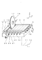
本発明に係る切断装置の実施例1を、図1を参照して説明する。図1は、本実施例に係る切断装置の要部を示す概略斜視図である。図1に示されているように、本実施例に係る切断装置が有する吸着用治具6には、樹脂封止体1が吸着固定されている。樹脂封止体1は、Y方向に沿う1つの境界線4からなる被切断線20において回転刃17によって切断されている。その被切断線20には、Y方向に延びる溝14のうちの1つの溝である切断部溝21が、平面視した場合に重なっている。そして、切断部溝21には、回転刃17の外縁である周端部が収容される。
A cutting apparatus according to a first embodiment of the present invention will be described with reference to FIG. FIG. 1 is a schematic perspective view showing a main part of the cutting apparatus according to the present embodiment. As shown in FIG. 1, the
吸着用治具6における側方(図1では前方)の近傍には、回転刃17と一体的に洗浄水用ノズル22が設けられている。洗浄水用ノズル22は、切断部溝21が延びる方向に洗浄水用ノズル22の中心軸がほぼ沿うようにして、水平又はわずかに下向きに設けられている。また、洗浄水用ノズル22は、発生した切断くずが切削水19によって排出される方向(−Y方向)に向いて設けられている。ここで、「吸着用治具6の側方の近傍」というときの「側方の近傍」とは、図示されている治具の4つの側面(正面、背面、右側面、左側面)の近傍を意味する。
A washing water nozzle 22 is provided integrally with the
これらの構成によって、洗浄水用ノズル22は、切断部溝21が延びる方向かつ切断くずが排出される方向に、その切断部溝21に向かって高圧の洗浄水23を直接噴射し、高圧の洗浄水23を切断部溝21の内部において高速で流動させることができる。また、洗浄水用ノズル22を、その中心軸がわずかに下向きになるように設けることによって、洗浄水23を切断部溝21の底面に衝突させた後に切断部溝21の内部において高速で流動させることができる。 With these configurations, the cleaning water nozzle 22 directly injects the high-pressure cleaning water 23 toward the cutting portion groove 21 in the direction in which the cutting portion groove 21 extends and the cutting waste is discharged, thereby cleaning the high pressure. The water 23 can flow at a high speed inside the cut groove 21. Further, by providing the cleaning water nozzle 22 so that the central axis thereof is slightly downward, the cleaning water 23 is caused to flow at a high speed inside the cutting portion groove 21 after colliding with the bottom surface of the cutting portion groove 21. be able to.
図1に示された切断装置は、次のようにして樹脂封止体1を切断する。まず、切断しようとするY方向に沿う境界線4に対して、X,Y,Z方向において回転刃17を位置合わせする。
The cutting device shown in FIG. 1 cuts the
次に、切削水19と洗浄水23とを噴射させながら、樹脂封止体1に向かって切断機構15を+Y方向に移動させる。これによって、樹脂封止体1を被切断線20に沿って切断する。ここで、洗浄水用ノズル22は、切断部溝21に向かってその切断部溝21が延びる方向に、かつ、切断くずが排出される方向(−Y方向)に、高圧の洗浄水23を直接噴射する。したがって、回転刃17によって発生した切断くずは、切断部溝21の内部を−Y方向に向かって高速で流動する洗浄水23によって、切断部溝21から吸着用治具6の外部に除去される。
Next, the cutting mechanism 15 is moved in the + Y direction toward the
次に、Y方向に沿う境界線4の全てにおいて樹脂封止体1を切断した後に、吸着用治具6が取り付けられたベース7(図7参照)をθ方向に90°だけ回動させる。その後に、新たにY方向に沿うことになった境界線4のそれぞれにおいて樹脂封止体1を切断する。洗浄水23を噴射することについては、最初のY方向における切断の場合と同様である。ここまでの工程により、樹脂封止体1を切断して、各領域5にそれぞれ対応する電子部品に個片化することができる。
Next, after cutting the
本実施例によれば、被切断線20に重なる切断部溝21に向かってその切断部溝21が延びる方向に、かつ、切断くずが排出される方向(−Y方向)に、高圧の洗浄水23を直接噴射する。これにより、切断部溝21に向かって直接噴射された洗浄水23が、その切断部溝21の内部における長さ方向の全ての部分において、切断くずが排出される方向に高速で流動する。したがって、切断部溝21の内部に残っており切断くずを含む液体が、切断部溝21の内部から吸着用治具6の外部に除去される。
According to this embodiment, high-pressure washing water is formed in the direction in which the cut groove 21 extends toward the cut groove 21 that overlaps the
本発明に係る切断装置の実施例2を、図2を参照して説明する。図2は、本実施例に係る切断装置の要部を示す概略斜視図である。図2に示されているように、吸着用治具6における側方(図1では前方)の近傍には、切断機構15と一体的に2個の洗浄水用ノズル22,24が設けられている。洗浄水用ノズル24は、その時点で切断されている被切断線20の直前に切断された境界線25に重なる溝26に向かって、設けられている。そして、洗浄水用ノズル24は、その溝26が延びる方向に、かつ、切断くずが排出される方向(−Y方向)に、高圧の洗浄水23を直接噴射する。
A cutting apparatus according to a second embodiment of the present invention will be described with reference to FIG. FIG. 2 is a schematic perspective view illustrating a main part of the cutting device according to the present embodiment. As shown in FIG. 2, two washing water nozzles 22 and 24 are provided integrally with the cutting mechanism 15 in the vicinity of the side (front in FIG. 1) of the
本実施例によれば、その時点で切断されている被切断線20に重なる切断部溝21に高圧の洗浄水23が直接噴射される。加えて、直前に切断された境界線25に重なる溝26にも、洗浄水23が直接噴射される。したがって、直前に切断された境界線25に重なる溝26には、その境界線25自身において被切断物1が切断された時と、その直後に隣の境界線である被切断線20において被切断物1が切断される時との2回にわたって、洗浄水23が直接噴射される。このことによって、直前に切断された境界線25に重なる溝26、言い換えれば既に切断され終わった境界線25に重なる溝26の内部に残っており切断くずを含む液体がその1つの溝26から除去される効果が増大する。
According to the present embodiment, the high-pressure cleaning water 23 is directly jetted into the cut groove 21 that overlaps the
なお、洗浄水用ノズル24は、その時点で切断されている被切断線20よりも以前に切断された境界線(直前に切断された境界線に限らない)に重なる溝に向かって、設けられていればよい。また、洗浄水用ノズル24は、その時点で切断されている被切断線20よりも以前に切断された境界線に重なる溝に向かって、2個以上設けられていてもよい。また、2個以上設けられた洗浄水用ノズル24のうち少なくとも1個が、その時点で切断されている被切断線20よりも以前に切断された境界線に重なる溝に向かって、設けられていればよい。更に、2個以上設けられた洗浄水用ノズル24には、これから切断しようとする境界線に重なる溝に向かって設けられているノズルが含まれていてもよい。
The cleaning water nozzle 24 is provided toward a groove that overlaps a boundary line (not limited to the boundary line that was cut immediately before) that is cut before the cutting
また、その時点で切断されている被切断線20に重なる溝21に向かって洗浄水23を噴射することなく、既に切断され終わった境界線25に重なる溝26に向かって洗浄水23を噴射することとしてもよい。言い換えれば、洗浄水用ノズル24のみを1個又は複数個設けてもよい。更に、既に切断され終わった境界線25に重なる溝26と、まだ切断されていない境界線4に重なる溝14とに向かって、洗浄水23を噴射することとしてもよい。
In addition, the cleaning water 23 is sprayed toward the groove 26 that overlaps the boundary line 25 that has already been cut without spraying the cleaning water 23 toward the groove 21 that overlaps the
なお、ここまで説明した実施例1と実施例2とにおいては、切断機構15と一体的に洗浄水用ノズル22,24が設けられていることとした。これに限らず、洗浄水用ノズル22,24を、切断機構15とは分離して設けることもできる。この場合には、洗浄水用ノズル22,24を、X方向には切断機構15に同期して移動させ、Y方向には切断機構15とは非同期で移動させてもよい。 In the first and second embodiments described so far, the cleaning water nozzles 22 and 24 are provided integrally with the cutting mechanism 15. Not only this but the nozzles 22 and 24 for washing water can also be provided separately from the cutting mechanism 15. In this case, the cleaning water nozzles 22 and 24 may be moved in the X direction in synchronization with the cutting mechanism 15 and may be moved in the Y direction asynchronously with the cutting mechanism 15.
また、複数個の洗浄水用ノズル22,24間のピッチ(中心間距離)を可変にできる構成を採用してもよい。これにより、電子部品のサイズ、言い換えれば境界線4の間隔が変わった場合においても複数個の洗浄水用ノズル22,24自体を変更する必要がないという効果が得られる。
Moreover, you may employ | adopt the structure which can vary the pitch (distance between centers) between the nozzles 22 and 24 for several washing water. Thereby, even when the size of the electronic component, in other words, the interval between the
本発明に係る切断装置の実施例3を、図3を参照して説明する。図3は、本実施例に係る切断装置の要部を示す概略斜視図である。図3に示されているように、吸着用治具6における側方(図1では前方)の近傍には、回転刃17とは分離して、X方向に沿って延びる長尺の洗浄水用ノズル27が設けられている。洗浄水用ノズル27は、切断しようとする方向(Y方向)に沿う全ての溝14にそれぞれ対向する複数の噴射口(図示なし)を有する。そして、洗浄水用ノズル27が有する複数の噴射口は、すべての溝14に対して、それらの溝14が延びる方向に、かつ、切断くずが排出される方向(−Y方向)に、高圧の洗浄水23をそれぞれ直接噴射する。
A third embodiment of the cutting device according to the present invention will be described with reference to FIG. FIG. 3 is a schematic perspective view illustrating a main part of the cutting device according to the present embodiment. As shown in FIG. 3, in the vicinity of the side (front in FIG. 1) of the
本実施例によれば、常時、すべての溝14に対して、高圧の洗浄水23がそれぞれ直接噴射される。これにより、その時点で切断されている被切断線20に重なる溝21に加えて、それ以前に切断された境界線(直前に切断された境界線25を含む)に重なる溝(溝26を含む)を含む他の溝14にも、高圧の洗浄水23がそれぞれ直接噴射される。したがって、全ての溝14に重なる境界線4において被切断物1が切断された後においても、全ての溝14に向かって洗浄水23が直接噴射される。よって、全ての溝14において、内部に残っており切断くずを含む液体が除去される効果が増大する。
According to the present embodiment, the high-pressure washing water 23 is directly jetted to all the
なお、すべての噴射口間のピッチ(隣接する噴射口間の中心間距離)が異なる複数の洗浄水用ノズル27を準備しておいてもよい。これにより、電子部品のサイズ、言い換えれば境界線4の間隔が変わった場合においてもノズル自体を交換することによって対応できるという効果が得られる。
In addition, you may prepare the several nozzle 27 for washing water from which the pitch (center distance between adjacent injection ports) from which all the injection ports differ. Thereby, even when the size of the electronic component, in other words, the interval between the
本発明に係る切断装置の実施例4を、図4を参照して説明する。図4は、本実施例に係る切断装置の要部を示す概略斜視図である。図4に示されているように、吸着用治具6における側方(図1では前方)の近傍には、回転刃17とは分離して、X方向に沿って延びる長尺の洗浄水用ノズル28が設けられている。洗浄水用ノズル28は、切断しようとする方向(Y方向)に沿う全ての溝14に対向してX方向に沿って延びる、1個のスリット状の噴射口を有する。そして、洗浄水用ノズル28は、すべての溝14に対して、それらの溝14が延びる方向に、かつ、切断くずが排出される方向(−Y方向)に、X方向とY方向とに延びてZ方向に小さい厚さを有する膜状(カーテン状)で高圧の洗浄水29を直接噴射する。
A cutting apparatus according to a fourth embodiment of the present invention will be described with reference to FIG. FIG. 4 is a schematic perspective view illustrating a main part of the cutting device according to the present embodiment. As shown in FIG. 4, in the vicinity of the side (front in FIG. 1) of the
本実施例によれば、洗浄水29は膜状の形状を有するので、常時、すべての溝14に対して、高圧の洗浄水29がそれぞれ直接噴射される。したがって、実施例3と同様の効果が得られる。加えて、本実施例によれば、電子部品のサイズ、言い換えれば境界線4の間隔が変わった場合においてもノズル自体を変更する必要がないという効果が得られる。
According to the present embodiment, since the cleaning water 29 has a film shape, the high-pressure cleaning water 29 is always directly sprayed to all the
なお、本実施例の説明では、洗浄水用ノズル28が1個のスリット状の噴射口を有することとした。これに限らず、洗浄水用ノズル28の噴射口は、X方向に沿って延びる複数個のスリット状の噴射口であってもよい。また、X方向に沿って複数の洗浄水用ノズル28を設けてもよい。また、1個又は複数個のスリット状の噴射口を設けて、それらの噴射口が扇状に拡がる洗浄水を噴射することとしてもよい。 In the description of the present embodiment, the cleaning water nozzle 28 has one slit-shaped injection port. Not limited to this, the ejection port of the cleaning water nozzle 28 may be a plurality of slit-shaped ejection ports extending along the X direction. A plurality of cleaning water nozzles 28 may be provided along the X direction. Moreover, it is good also as providing one or several slit-shaped injection nozzles, and injecting the washing water which those injection nozzles expand in fan shape.
また、ここまで説明した実施例1〜4において洗浄水23、29に必要な条件は、洗浄水23、29が、切断部溝21及び溝26の内部における長さ方向の全ての部分において切断くずが排出される方向に高速で流動することである。したがって、切断部溝21及び溝26に向かって噴射された洗浄水23、29の圧力、噴射速度、断面形状、断面積等については、上述した条件を満たすように定めればよい。洗浄水用ノズル22、24、27、28の噴射口と切断部溝21及び溝26の開口との距離についても、上述した条件を満たすように定めればよい。 Further, in the first to fourth embodiments described so far, the conditions necessary for the cleaning waters 23 and 29 are that the cleaning waters 23 and 29 are cut scraps in all the lengthwise portions inside the cutting groove 21 and the groove 26. Is to flow at high speed in the direction of discharge. Therefore, the pressure, the spray speed, the cross-sectional shape, the cross-sectional area, and the like of the cleaning water 23 and 29 sprayed toward the cut groove 21 and the groove 26 may be determined so as to satisfy the above-described conditions. What is necessary is just to determine so that the distance of the injection port of the nozzles 22,24,27,28 for washing water and the opening of the cutting part groove | channel 21 and the groove | channel 26 may satisfy | fill the above-mentioned conditions.
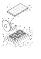
本発明に係る切断装置の実施例5を、図5を参照して説明する。図5は、本実施例に係る切断装置の要部を示す概略斜視図である。図5に示されているように、吸着用治具6における溝13,14の底面には、複数の吸引孔30が設けられている。複数の吸引孔30は、吸着用治具6及びベース7の内部に設けられた吸引管(図示なし)と吸引用配管31とを順次経由して、真空ポンプや減圧タンク等の吸引源32につながっている。そして、回転刃17によって樹脂封止体1が切断されている間、溝13,14の内部に溜まっている液体は、複数の吸引孔30を経由して吸引されることによって排水33として吸着用治具6の外部に除去される。
本実施例によれば、複数の溝13,14の底面に設けられ吸引源32につながっている複数の吸引孔30によって、溝13,14の内部が吸引される。このことにより、複数の溝13,14の内部に残っており切断くずを含む液体が吸引されて吸着用治具6の外部、ひいては切断装置の外部に除去される。したがって、複数の溝13,14の内部が洗浄される。
According to the present embodiment, the inside of the
ところで、溝13,14の内部において複数の吸引孔30が設けられる場所と数とについては、特に限定されるものではなく任意に定めることができる。しかし、それらの場所は、図に示されているように溝13,14の交差点であることが好ましい。これにより、複数の溝13,14の内部において切断くずを含む液体が溜まりやすい交差点において、溜まっている液体が切断装置の外部に除去される効果が高まる。
By the way, the location and the number of the suction holes 30 provided in the
本発明に係る切断装置の実施例6を、図6を参照して説明する。図6は、本実施例に係る切断装置の要部を示す概略斜視図である。図6に示されているように、吸着用治具6における溝13,14の底面には、複数の吸引孔30と複数の供給孔34とが相隣り合って設けられている。図6では、吸引孔30は楕円の内部に「X」を付して、供給孔34は楕円の内部に「・」を付して、それぞれ示されている。複数の供給孔34は、吸着用治具6及びベース7の内部に設けられている供給管(図示なし)と供給用配管35とを順次経由して、洗浄水の供給源36につながっている。
A sixth embodiment of the cutting device according to the present invention will be described with reference to FIG. FIG. 6 is a schematic perspective view illustrating a main part of the cutting device according to the present embodiment. As shown in FIG. 6, a plurality of suction holes 30 and a plurality of supply holes 34 are provided adjacent to each other on the bottom surfaces of the
回転刃17によって樹脂封止体1が切断されている間、複数の供給孔34は溝13,14の内部に洗浄水37を供給する。そして、複数の供給孔34から供給された洗浄水37は、複数の吸引孔30を経由して吸引されることによって排水38として吸着用治具6の外部、ひいては切断装置の外部に除去される。したがって、溝13,14の内部に溜まっている液体は、その排水38に混じって吸着用治具6の外部に除去される。
While the
本実施例によれば、複数の供給孔34から供給された洗浄水37が複数の吸引孔30を経由して吸引されることによって、排水38として吸着用治具6の外部に除去される。これにより、複数の溝13,14の内部に残っており切断くずを含む液体が吸引されて、排水38に混じって吸着用治具6の外部、ひいては切断装置の外部に除去される。したがって、複数の溝13,14の内部が効果的に洗浄される。
According to the present embodiment, the cleaning
ところで、溝13,14の内部において、複数の吸引孔30と複数の供給孔34とが相隣り合って設けられていることとした。複数の吸引孔30と複数の供給孔34とが設けられる場所と数とについては、特に限定されるものではなく任意に定めることができる。しかし、それらの場所は、図に示されているように溝13,14の交差点であることが好ましい。これにより、複数の溝13,14の内部において切断くずを含む液体が溜まりやすい交差点において、溜まっている液体が切断装置の外部に除去される効果が高まる。
By the way, inside the
なお、上述した各実施例において、被切断物としての樹脂封止体1は、その樹脂封止体1を切断してLEDパッケージ、CCD等の光素子(光学系電子部品)を製造する場合における、透光性樹脂を含む樹脂封止体であってもよい。また、被切断物は、透光性樹脂を含む樹脂成形体を切断して光学レンズ、光通信部品、導光板等の光学系の物品を製造する場合における樹脂成形体であってもよい。特に、光素子や光学系の物品を製造する場合における切断くずの付着は、歩留まり低下の原因になる。そして、本発明によれば、光素子や光学系の物品に切断くずが付着することを防止することによって、光素子や光学系の物品を製造する際の歩留まりを向上させることができる。
In each of the above-described embodiments, the
また、被切断物は、樹脂封止体以外に、シリコンウェーハ、化合物半導体ウエーハ等のウエーハ類、ガラス基板、セラミックス基板等の基板類であってもよい。言い換えれば、被切断物を切断して個片化する際に切断くずの付着を避けたいような場合において、本発明を適用することができる。 In addition to the resin sealing body, the object to be cut may be a wafer such as a silicon wafer or a compound semiconductor wafer, or a substrate such as a glass substrate or a ceramic substrate. In other words, the present invention can be applied to the case where it is desired to avoid the attachment of cutting waste when the workpiece is cut into pieces.
また、洗浄水用ノズルの噴射口を縦長にして、切削水用ノズルと洗浄水用ノズルとを共通化してもよい。この場合には、切削水・洗浄水兼用ノズルが、切削場所と切断部溝との双方に向かって水を噴射することになる。また、洗浄水用ノズルと同様の形状を有する切削水用ノズルを、洗浄水用ノズルに対してZ方向に並べて設けることもできる。 Further, the nozzle for cleaning water may be made vertically long so that the nozzle for cutting water and the nozzle for cleaning water are made common. In this case, the cutting water / cleaning water combined nozzle jets water toward both the cutting place and the cut groove. Moreover, the nozzle for cutting water which has the same shape as the nozzle for washing water can also be provided along with the Z direction with respect to the nozzle for washing water.
また、1枚の回転刃17を使用する実施例について説明した。これに限らず、切断装置には複数の回転刃17が設けられていてもよい。
Moreover, the Example using the one
また、ここまでの説明における「切削水」は、加工抵抗の低減(潤滑)と冷却と切断によって発生する切りくずの除去とを目的として供給される液体、すなわち切削液の総称である。また、「洗浄水」は、切断によって発生する切りくずの除去を主な目的として供給される液体、すなわち洗浄液の総称である。そして、「切削水」と「洗浄水」とのいずれについても、通常は市水又は純水が使用される。また、「切削水」と「洗浄水」として、市水又は純水に添加剤(洗剤、潤滑剤等)を添加した液体を使用してもよい。 In addition, the “cutting water” in the description so far is a general term for liquids supplied for the purpose of reducing machining resistance (lubrication) and cooling and removing chips generated by cutting, that is, cutting fluid. “Washing water” is a generic term for liquids supplied mainly for the purpose of removing chips generated by cutting, that is, cleaning liquids. For both “cutting water” and “washing water”, city water or pure water is usually used. Further, as “cutting water” and “washing water”, a liquid obtained by adding an additive (detergent, lubricant, etc.) to city water or pure water may be used.
また、吸着用治具6を使用して被切断物である樹脂封止体1を吸着固定した。これに限らず、被切断物や個片化された後の物品等の寸法形状によっては、クランプ等を使用して被切断物を固定してもよい。
Moreover, the
また、上述した各実施例においては、被切断物を完全に切断する「フルカット」について説明した。これに限らず、被切断物の厚み方向の一部を残して被切断物を切削(部分的に切断)する、いわゆる「ハーフカット」に対して本発明を適用することもできる。ハーフカットの場合においても、切断くずを含む切削水19が吸着用治具6の溝13,14に入り込むことがあるので(図1参照)、本発明は有効である。
Moreover, in each Example mentioned above, "full cut" which cut | disconnects a to-be-cut object completely was demonstrated. However, the present invention is not limited to this, and the present invention can also be applied to so-called “half cut” in which a part to be cut is cut (partially cut) while leaving a part in the thickness direction of the part to be cut. Even in the case of half-cutting, the cutting water 19 including cutting waste may enter the
また、本発明は、上述の各実施例に限定されるものではなく、本発明の趣旨を逸脱しない範囲内で、必要に応じて、任意にかつ適宜に組み合わせ、変更し、又は選択して採用できるものである。 In addition, the present invention is not limited to the above-described embodiments, and may be arbitrarily combined, changed, or selected as necessary without departing from the spirit of the present invention. It can be done.
1 樹脂封止体(被切断物)
2 基板
3 硬化樹脂
4 境界線
5 領域
6 吸着用治具(治具)
7 ベース
8 突起
9 凹部
10 吸引孔
11 吸引用配管
12 吸引源
13、14、26 溝
15 切断機構
16 回転軸
17 回転刃
18 切削水用ノズル(吐出手段)
19 切削水
20 被切断線
21 切断部溝
22、24、27、28 洗浄水用ノズル
23、29、37 洗浄水(洗浄液)
25 直前に切断された境界線(既に切断され終わった境界線)
30 吸引孔
31 吸引用配管
32 吸引源
33、38 排水
34 供給孔
35 供給用配管
36 供給源
1 Resin sealing body (object to be cut)
2
7
19
25 Borderline cut just before (boundary line that has already been cut)
30 Suction hole 31 Suction pipe 32 Suction source 33, 38 Drainage 34 Supply hole 35 Supply pipe 36 Supply source
Claims (10)
前記治具の側方に設けられ、前記複数の溝のうち前記回転刃が切断している1つの境界線からなる被切断線に重なる1つの溝に向かって前記1つの溝が延びる方向に洗浄液を噴射する噴射手段を備え、
前記噴射手段は、前記1つの溝に向かって前記洗浄液を噴射することによって該洗浄液を前記1つの溝の内部において高速で流動させ、
前記回転刃によって発生した切断くずが、前記1つの溝の内部を高速で流動する前記洗浄液によって、前記1つの溝から前記治具の外部に除去され、
前記噴射手段は、前記1つの溝が延びる方向に沿って水平又はわずかに下向きに設けられ、
前記噴射手段の向きが水平になることによって前記洗浄液を前記1つの溝に向かって直接噴射して前記1つの溝の内部において流動させることを、又は、前記噴射手段の向きがわずかに下向きになることによって前記洗浄液を前記1つの溝の底面に衝突させた後に前記1つの溝の内部において流動させることを、特徴とする切断装置。 A jig for fixing a workpiece having a plurality of regions provided in a lattice shape to a fixed surface, a plurality of grooves provided so as to overlap boundary lines of the plurality of regions on the fixed surface, and the boundary A cutting device for use in manufacturing a plurality of articles each corresponding to the region, comprising a rotary blade that cuts the workpiece along a line,
A cleaning liquid provided in a side of the jig and extending in a direction in which the one groove extends toward one groove that overlaps a cutting line that is formed by one boundary line cut by the rotary blade among the plurality of grooves. An injection means for injecting
The spraying means causes the cleaning liquid to flow at high speed inside the one groove by spraying the cleaning liquid toward the one groove,
Cutting waste generated by the rotary blade is removed from the one groove to the outside of the jig by the cleaning liquid flowing at high speed inside the one groove ,
The ejection means is provided horizontally or slightly downward along the direction in which the one groove extends,
When the direction of the jetting means is horizontal, the cleaning liquid is jetted directly toward the one groove to flow inside the one groove, or the direction of the jetting means is slightly downward. Thus, the cleaning liquid is caused to flow inside the one groove after colliding with the bottom surface of the one groove .
前記治具の側方に設けられ、前記複数の溝のうち既に切断され終わった境界線に重なる1つの溝に向かって前記1つの溝が延びる方向に洗浄液を噴射する噴射手段を備え、
前記噴射手段は、前記1つの溝に向かって前記洗浄液を噴射することによって該洗浄液を前記1つの溝の内部において高速で流動させ、
前記回転刃によって発生した切断くずが、前記1つの溝の内部を高速で流動する前記洗浄液によって、前記1つの溝から前記治具の外部に除去され、
前記噴射手段は、前記1つの溝が延びる方向に沿って水平又はわずかに下向きに設けられ、
前記噴射手段の向きが水平になることによって前記洗浄液を前記1つの溝に向かって直接噴射して前記1つの溝の内部において流動させることを、又は、前記噴射手段の向きがわずかに下向きになることによって前記洗浄液を前記1つの溝の底面に衝突させた後に前記1つの溝の内部において流動させることを、特徴とする切断装置。 A jig for fixing a workpiece having a plurality of regions provided in a lattice shape to a fixed surface, a plurality of grooves provided so as to overlap boundary lines of the plurality of regions on the fixed surface, and the boundary A cutting device for use in manufacturing a plurality of articles each corresponding to the region, comprising a rotary blade that cuts the workpiece along a line,
An ejection unit that is provided on a side of the jig and injects a cleaning liquid in a direction in which the one groove extends toward one groove that overlaps a boundary line that has already been cut among the plurality of grooves;
The spraying means causes the cleaning liquid to flow at high speed inside the one groove by spraying the cleaning liquid toward the one groove,
Cutting waste generated by the rotary blade is removed from the one groove to the outside of the jig by the cleaning liquid flowing at high speed inside the one groove ,
The ejection means is provided horizontally or slightly downward along the direction in which the one groove extends,
When the direction of the jetting means is horizontal, the cleaning liquid is jetted directly toward the one groove to flow inside the one groove, or the direction of the jetting means is slightly downward. Thus, the cleaning liquid is caused to flow inside the one groove after colliding with the bottom surface of the one groove .
前記噴射手段は、前記1つの溝を含むとともに前記1つの溝と同じ方向に延びる1又は複数の溝に向かって前記洗浄液を噴射するとともに、
前記1又は複数の溝のうち少なくとも1つの溝は、前記被切断線よりも以前に切断された境界線に重なる溝であることを特徴とする切断装置。 The cutting device according to claim 1 or 2,
The spraying means includes the one groove and sprays the cleaning liquid toward one or a plurality of grooves extending in the same direction as the one groove.
At least one groove among the one or more grooves is a groove that overlaps a boundary line cut before the cutting line.
前記噴射手段は、前記1つの溝を含むとともに前記1つの溝と同じ方向に延びる複数の溝に向かって前記洗浄液を膜状に噴射することを特徴とする切断装置。 In the cutting device according to any one of claims 1 to 3 ,
The said spraying means sprays the said washing | cleaning liquid in a film | membrane shape toward the several groove | channel extended in the same direction as the said 1 groove | channel while containing the said 1 groove | channel.
前記回転刃を有する切断機構を備え、
前記噴射手段は前記切断機構とは分離して設けられ、
前記噴射手段は前記切断機構に同期して前記治具の側方において前記複数の溝を横切るようにして移動することを特徴とする切断装置。 In the cutting device according to any one of claims 1 to 4 ,
A cutting mechanism having the rotary blade;
The injection means is provided separately from the cutting mechanism,
The cutting device is characterized in that the injection means moves so as to cross the plurality of grooves on the side of the jig in synchronization with the cutting mechanism.
前記複数の領域を区切る複数の境界線に各々対応して治具の固定面に設けられた複数の溝と前記複数の境界線とを各々位置合わせする工程と、
前記被切断物を前記固定面に固定する工程と、
回転刃によって前記複数の境界線のうち1つの境界線からなる被切断線に沿って前記被切断物を切断する工程と、
噴射手段を使用して、前記複数の溝のうち前記被切断線に重なる1つの溝に向かって、前記治具の側方から前記1つの溝が延びる方向に洗浄液を噴射する工程とを備え、
前記洗浄液を噴射する工程では、前記噴射手段の向きが前記1つの溝が延びる方向に沿って水平になるようにして前記1つの溝に向かって前記洗浄液を直接噴射して該洗浄液を前記1つの溝の内部において高速で流動させることによって、又は、前記噴射手段の向きが前記1つの溝が延びる方向に沿ってわずかに下向きになるようにして前記1つの溝に向かって前記洗浄液を噴射して該洗浄液を前記1つの溝の底面に衝突させた後に前記1つの溝の内部において高速で流動させることによって、前記回転刃によって発生した切断くずを前記1つの溝から前記治具の外部に除去することを特徴とする切断方法。 A cutting method of forming a plurality of articles each corresponding to the region by cutting a workpiece having a plurality of regions provided in a lattice shape,
Aligning the plurality of grooves with the plurality of grooves provided on the fixing surface of the jig corresponding to the plurality of boundary lines that divide the plurality of regions, respectively.
Fixing the workpiece to the fixing surface;
Cutting the workpiece along a cutting line consisting of one boundary line among the plurality of boundary lines by a rotary blade;
Spraying the cleaning liquid in a direction in which the one groove extends from the side of the jig toward one groove overlapping the line to be cut among the plurality of grooves using an injection unit,
In the step of spraying the cleaning liquid, the cleaning liquid is directly sprayed toward the one groove so that the direction of the spraying unit is horizontal along the direction in which the one groove extends, and the cleaning liquid is sprayed into the one groove. The cleaning liquid is sprayed toward the one groove by flowing at a high speed inside the groove, or in such a manner that the direction of the ejection means is slightly downward along the direction in which the one groove extends. By causing the cleaning liquid to collide with the bottom surface of the one groove and then flowing at a high speed inside the one groove, cutting waste generated by the rotary blade is removed from the one groove to the outside of the jig. The cutting method characterized by the above-mentioned.
前記複数の領域を区切る複数の境界線に各々対応して治具の固定面に設けられた複数の溝と前記複数の境界線とを各々位置合わせする工程と、
前記被切断物を前記固定面に固定する工程と、
回転刃によって前記複数の境界線のうち1つの境界線からなる被切断線に沿って前記被切断物を切断する工程と、
噴射手段を使用して、前記複数の溝のうち既に切断され終わった境界線に重なる1つの溝に向かって、前記治具の側方から前記1つの溝が延びる方向に洗浄液を噴射する工程とを備え、
前記洗浄液を噴射する工程では、前記噴射手段の向きが前記1つの溝が延びる方向に沿って水平になるようにして前記1つの溝に向かって前記洗浄液を直接噴射して該洗浄液を前記1つの溝の内部において高速で流動させることによって、又は、前記噴射手段の向きが前記1つの溝が延びる方向に沿ってわずかに下向きになるようにして前記1つの溝に向かって前記洗浄液を噴射して該洗浄液を前記1つの溝の底面に衝突させた後に前記1つの溝の内部において高速で流動させることによって、前記回転刃によって発生した切断くずを前記1つの溝から前記治具の外部に除去することを特徴とする切断方法。 A cutting method of forming a plurality of articles each corresponding to the region by cutting a workpiece having a plurality of regions provided in a lattice shape,
Aligning the plurality of grooves with the plurality of grooves provided on the fixing surface of the jig corresponding to the plurality of boundary lines that divide the plurality of regions, respectively.
Fixing the workpiece to the fixing surface;
Cutting the workpiece along a cutting line consisting of one boundary line among the plurality of boundary lines by a rotary blade;
A step of spraying a cleaning liquid in a direction in which the one groove extends from a side of the jig toward one groove that overlaps a boundary line that has already been cut among the plurality of grooves using an injection unit; With
In the step of spraying the cleaning liquid, the cleaning liquid is directly sprayed toward the one groove so that the direction of the spraying unit is horizontal along the direction in which the one groove extends, and the cleaning liquid is sprayed into the one groove. The cleaning liquid is sprayed toward the one groove by flowing at a high speed inside the groove, or in such a manner that the direction of the ejection means is slightly downward along the direction in which the one groove extends. By causing the cleaning liquid to collide with the bottom surface of the one groove and then flowing at a high speed inside the one groove, cutting waste generated by the rotary blade is removed from the one groove to the outside of the jig. The cutting method characterized by the above-mentioned.
前記洗浄液を噴射する工程では前記1つの溝を含むとともに前記1つの溝と同じ方向に延びる1又は複数の溝に向かって前記洗浄液を噴射するとともに、
前記1又は複数の溝のうち少なくとも1つの溝は、前記被切断線よりも以前に切断された境界線に重なる溝であることを特徴とする切断方法。 The cutting method according to claim 6 or 7 ,
In the step of spraying the cleaning liquid, the cleaning liquid is sprayed toward one or a plurality of grooves including the one groove and extending in the same direction as the one groove,
The cutting method according to claim 1, wherein at least one of the one or more grooves is a groove that overlaps a boundary line cut before the line to be cut.
前記洗浄液を噴射する工程では、前記1つの溝を含むとともに前記1つの溝と同じ方向に延びる複数の溝に向かって前記洗浄液を膜状に噴射することを特徴とする切断方法。 In the cutting method according to any one of claims 6 to 8 ,
In the step of spraying the cleaning liquid, the cleaning liquid is sprayed in a film shape toward a plurality of grooves including the one groove and extending in the same direction as the one groove.
前記洗浄液を噴射する工程では、前記噴射手段を、前記回転刃を有する切断機構に同期して前記治具の側方において前記複数の溝を横切るようにして移動させることを特徴とする切断方法。 In the cutting method according to any one of claims 6 to 9 ,
In the step of injecting the cleaning liquid, the injection means is moved so as to cross the plurality of grooves on the side of the jig in synchronization with a cutting mechanism having the rotary blade.
Priority Applications (3)
| Application Number | Priority Date | Filing Date | Title |
|---|---|---|---|
| JP2008049048A JP5363746B2 (en) | 2008-02-29 | 2008-02-29 | Cutting apparatus and cutting method |
| PCT/JP2009/000377 WO2009107324A1 (en) | 2008-02-29 | 2009-02-02 | Cutter and cutting method |
| TW098104290A TWI451930B (en) | 2008-02-29 | 2009-02-11 | Cutting device and cutting method |
Applications Claiming Priority (1)
| Application Number | Priority Date | Filing Date | Title |
|---|---|---|---|
| JP2008049048A JP5363746B2 (en) | 2008-02-29 | 2008-02-29 | Cutting apparatus and cutting method |
Related Child Applications (1)
| Application Number | Title | Priority Date | Filing Date |
|---|---|---|---|
| JP2012227358A Division JP2013010180A (en) | 2012-10-12 | 2012-10-12 | Cutting device and cutting method |
Publications (3)
| Publication Number | Publication Date |
|---|---|
| JP2009202311A JP2009202311A (en) | 2009-09-10 |
| JP2009202311A5 JP2009202311A5 (en) | 2011-11-04 |
| JP5363746B2 true JP5363746B2 (en) | 2013-12-11 |
Family
ID=41015731
Family Applications (1)
| Application Number | Title | Priority Date | Filing Date |
|---|---|---|---|
| JP2008049048A Active JP5363746B2 (en) | 2008-02-29 | 2008-02-29 | Cutting apparatus and cutting method |
Country Status (3)
| Country | Link |
|---|---|
| JP (1) | JP5363746B2 (en) |
| TW (1) | TWI451930B (en) |
| WO (1) | WO2009107324A1 (en) |
Families Citing this family (10)
| Publication number | Priority date | Publication date | Assignee | Title |
|---|---|---|---|---|
| JP5709370B2 (en) * | 2009-11-26 | 2015-04-30 | 株式会社ディスコ | Cutting apparatus and cutting method |
| JP5468886B2 (en) * | 2009-12-02 | 2014-04-09 | アピックヤマダ株式会社 | Cutting apparatus and cutting method |
| DE102010031364A1 (en) * | 2010-07-15 | 2012-01-19 | Gebr. Schmid Gmbh & Co. | Support for a silicon block, carrier arrangement with such a carrier and method for producing such a carrier arrangement |
| JP5627618B2 (en) * | 2012-02-23 | 2014-11-19 | Towa株式会社 | Fixing jig manufacturing method and fixing jig |
| JP5975703B2 (en) * | 2012-04-09 | 2016-08-23 | 株式会社ディスコ | Cutting equipment |
| JP6143668B2 (en) * | 2013-12-28 | 2017-06-07 | Towa株式会社 | Cutting apparatus and method for manufacturing electronic parts |
| JP6257360B2 (en) * | 2014-02-04 | 2018-01-10 | 株式会社ディスコ | Blade cover device |
| JP6228044B2 (en) * | 2014-03-10 | 2017-11-08 | 株式会社ディスコ | Processing method of plate |
| JP6338478B2 (en) * | 2014-07-18 | 2018-06-06 | Towa株式会社 | Cutting method and product manufacturing method |
| KR20170112003A (en) * | 2016-03-30 | 2017-10-12 | 동우 화인켐 주식회사 | Cutting machine of sheet type film |
Family Cites Families (8)
| Publication number | Priority date | Publication date | Assignee | Title |
|---|---|---|---|---|
| JPS6480506A (en) * | 1987-09-24 | 1989-03-27 | Hitachi Ltd | Dicer |
| JPH01101112A (en) * | 1987-10-15 | 1989-04-19 | Sony Corp | Dicing method for semiconductor water |
| JPH04240749A (en) * | 1991-01-25 | 1992-08-28 | Toshiba Corp | Dicing device |
| JPH0745562A (en) * | 1993-07-30 | 1995-02-14 | Sony Corp | Dicing method and device of semiconductor wafer |
| JP2003309087A (en) * | 2002-04-18 | 2003-10-31 | Towa Corp | Cutting method and device for substrate |
| JP2004055860A (en) * | 2002-07-22 | 2004-02-19 | Renesas Technology Corp | Semiconductor device fabricating process |
| JP4657688B2 (en) * | 2004-11-29 | 2011-03-23 | 株式会社ディスコ | Cutting equipment |
| JP4943688B2 (en) * | 2005-10-21 | 2012-05-30 | 株式会社ディスコ | Cutting equipment |
-
2008
- 2008-02-29 JP JP2008049048A patent/JP5363746B2/en active Active
-
2009
- 2009-02-02 WO PCT/JP2009/000377 patent/WO2009107324A1/en active Application Filing
- 2009-02-11 TW TW098104290A patent/TWI451930B/en active
Also Published As
| Publication number | Publication date |
|---|---|
| WO2009107324A1 (en) | 2009-09-03 |
| TWI451930B (en) | 2014-09-11 |
| JP2009202311A (en) | 2009-09-10 |
| TW201000249A (en) | 2010-01-01 |
Similar Documents
| Publication | Publication Date | Title |
|---|---|---|
| JP5363746B2 (en) | Cutting apparatus and cutting method | |
| JP2009202311A5 (en) | ||
| JP2009285769A (en) | Cutting device | |
| TWI543274B (en) | A method and a device for cutting a substrate | |
| KR19980085413A (en) | Wafer Sowing Device | |
| KR102478797B1 (en) | Cutting device | |
| CN104626376B (en) | Cutting apparatus | |
| JP6338478B2 (en) | Cutting method and product manufacturing method | |
| JP6096047B2 (en) | Cutting apparatus and package substrate processing method | |
| JP2013010180A (en) | Cutting device and cutting method | |
| JP2011114145A (en) | Cutting device and cutting method | |
| JP2016082195A (en) | Cutting device and cutting method | |
| JP2016181569A (en) | Method for cutting package substrate | |
| KR102365978B1 (en) | Cutting apparatus | |
| JP6333650B2 (en) | Cutting apparatus and cutting method | |
| CN110620046A (en) | Semiconductor sawing method and system | |
| JP2007069280A (en) | Cutting device | |
| KR101779701B1 (en) | Manufacturing apparatus and manufacturing method | |
| JP2018122413A (en) | Cutting blade and cutting method | |
| JP2020161615A (en) | Manufacturing method for package chip | |
| JP4783568B2 (en) | Cutting device and method for cutting workpiece | |
| JP2005159217A (en) | Manufacturing method and dicing apparatus for semiconductor device | |
| KR101780664B1 (en) | Method For Plating Holes And Apparatus For Plating Plate Having Holes Using That Method | |
| JP7076966B2 (en) | Manufacturing method for substrates and semiconductor devices | |
| JP2008100322A (en) | Water jet machining device |
Legal Events
| Date | Code | Title | Description |
|---|---|---|---|
| A621 | Written request for application examination |
Free format text: JAPANESE INTERMEDIATE CODE: A621 Effective date: 20101005 |
|
| A521 | Request for written amendment filed |
Free format text: JAPANESE INTERMEDIATE CODE: A523 Effective date: 20110920 |
|
| A131 | Notification of reasons for refusal |
Free format text: JAPANESE INTERMEDIATE CODE: A131 Effective date: 20120821 |
|
| A521 | Request for written amendment filed |
Free format text: JAPANESE INTERMEDIATE CODE: A523 Effective date: 20121016 |
|
| A02 | Decision of refusal |
Free format text: JAPANESE INTERMEDIATE CODE: A02 Effective date: 20130409 |
|
| A521 | Request for written amendment filed |
Free format text: JAPANESE INTERMEDIATE CODE: A523 Effective date: 20130605 |
|
| A911 | Transfer to examiner for re-examination before appeal (zenchi) |
Free format text: JAPANESE INTERMEDIATE CODE: A911 Effective date: 20130617 |
|
| TRDD | Decision of grant or rejection written | ||
| A01 | Written decision to grant a patent or to grant a registration (utility model) |
Free format text: JAPANESE INTERMEDIATE CODE: A01 Effective date: 20130820 |
|
| A61 | First payment of annual fees (during grant procedure) |
Free format text: JAPANESE INTERMEDIATE CODE: A61 Effective date: 20130906 |
|
| R150 | Certificate of patent or registration of utility model |
Ref document number: 5363746 Country of ref document: JP Free format text: JAPANESE INTERMEDIATE CODE: R150 Free format text: JAPANESE INTERMEDIATE CODE: R150 |
|
| R250 | Receipt of annual fees |
Free format text: JAPANESE INTERMEDIATE CODE: R250 |
|
| R250 | Receipt of annual fees |
Free format text: JAPANESE INTERMEDIATE CODE: R250 |
|
| R250 | Receipt of annual fees |
Free format text: JAPANESE INTERMEDIATE CODE: R250 |
|
| R250 | Receipt of annual fees |
Free format text: JAPANESE INTERMEDIATE CODE: R250 |
|
| R250 | Receipt of annual fees |
Free format text: JAPANESE INTERMEDIATE CODE: R250 |
|
| R250 | Receipt of annual fees |
Free format text: JAPANESE INTERMEDIATE CODE: R250 |
|
| R250 | Receipt of annual fees |
Free format text: JAPANESE INTERMEDIATE CODE: R250 |
|
| R250 | Receipt of annual fees |
Free format text: JAPANESE INTERMEDIATE CODE: R250 |
|
| R250 | Receipt of annual fees |
Free format text: JAPANESE INTERMEDIATE CODE: R250 |